1
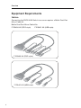
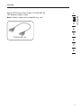
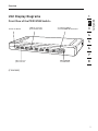
OmniView® PRO3
KVM Switch
User Manual
F1DA104Z
F1DA108Z
F1DA116Z
Table of Contents
1.
Introduction ...................................................................................... 1
Package Contents ......................................................................1
2.
Overview .......................................................................................... 2
Feature Overview ........................................................................2
Equipment Requirements ............................................................4
System Requirements .................................................................6
Unit Display Diagrams ................................................................7
Specifications .............................................................................9
3.
Installation ......................................................................................10
Pre-Configuration ..................................................................... 10
Mounting the PRO3 KVM Switch ............................................... 11
Connecting the Console to the PRO3 KVM Switch ..................... 14
Connecting Servers to the PRO3 KVM Switch ........................... 16
Connecting Multiple PRO3 KVM Switches (Daisy-Chaining) ....... 20
Powering Up the Systems ......................................................... 25
4.
Using your PRO3 KVM Switch ...........................................................26
Selecting a Server or BANK Using Hot-Key Commands ............. 26
Selecting a Server Using Direct-Access Port Selectors .............. 28
Selecting a BANK Using Scroll Buttons ..................................... 28
AutoScan Mode ........................................................................ 29
On-Screen Display (OSD) .......................................................... 30
Keyboard Hot-Key-Command Shortcuts .................................... 34
Sun Combo and Mac Key Mapping ........................................... 35
Updating Firmware ................................................................... 36
5.
Frequently Asked Questions ............................................................37
6.
Troubleshooting ..............................................................................39
7.
Glossary ..........................................................................................42
8.
Information .....................................................................................43
Introduction
Belkin has designed and developed this KVM Switch with the server
administrator in mind. The result is a KVM Switch that surpasses any other
switch on the market. The PRO3 KVM Switch is engineered to work with the
most advanced server-room and laboratory environments, offering intuitive port
indicators, direct-access port selectors, high video resolution support, and
flash-upgradeable firmware.
PRO3 KVM Switches can be daisy-chained together easily to enable
management of up to 256 PS/2 and/or USB servers from a single console. The
PRO3 KVM Switch also comes with an unparalleled Belkin 3-Year Warranty.
This User Manual will provide details about your new PRO3 KVM Switch, from
installation and operation to troubleshooting—in the unlikely event of a problem.
For quick and easy installation, please refer to the Quick Installation Guide
included in your PRO3 KVM Switch packaging.
Thank you for purchasing the Belkin OmniView PRO3 KVM Switch. We
appreciate your business and have confidence that you will soon see for yourself
why Belkin is the number-one-selling brand in KVM switches worldwide.
1
2
3
4
5
6
7
8
Package Contents
�������������
�����������
����������
�������������
�����������������
��������������
������������
�������������
�����
�����������
������
������������������
�������
���������������
1
section
Congratulations on your purchase
of this Belkin OmniView PRO3
KVM Switch (the KVM Switch).
Our diverse line of KVM solutions
exemplifies the Belkin commitment
to delivering high-quality, durable products at an affordable price.
Overview
Feature Overview
• Hot Keys
Hot-key functionality allows you to select a desired port using designated key
commands. By using a simple hot-key sequence on your keyboard, you can
select one server from as many as 256 servers, instantaneously.
• AutoScan
The AutoScan feature allows you to set your PRO3 KVM Switch to scan and
monitor the activities of all connected servers, one by one. The time interval
allotted for each server can be adjusted through the On-Screen Display
(OSD) menu.
• Video Resolution
The PRO3 KVM Switch supports video resolutions of up to 1920x1440@75Hz.
• Security
Allows you to specify user names and passwords to prevent unauthorized
users from accessing the OSD and KVM Switch.
• Dedicated Daisy-Chain Port
Up to 16 KVM switches can be daisy-chained together using dedicated
ports, so you can easily expand your KVM configuration as your server
environment grows.
• On-Screen Display (OSD)
The OSD feature simplifies server management by allowing you to assign
individual names to each connected server throughout the system. It provides
a visual means of switching between servers and assigning the hot-key
scheme. The OSD can also be set up to support regional languages.
• Front-Panel Push Buttons
Direct-access port selectors, located conveniently on the front panel of the
PRO3 KVM Switch, allow for simple, manual port-selection.
2
Overview
• LED Display
• 7-Segment LED Display
When daisy-chaining multiple PRO3 KVM Switches together, the 7-segment
LED display serves as a quick indicator of the selected BANK.
• Flash Upgrade
Flash-upgradeable firmware allows you to install the latest firmware on your
PRO3 KVM Switch. This enables your KVM Switch to maintain consistent
compatibility with the latest devices and servers. Firmware upgrades are free
for the life of your PRO3 KVM Switch and can be downloaded from Belkin’s
support website at www.belkin.com/support.
1
2
3
4
5
6
7
8
3
section
An LED display on the front panel of the PRO3 KVM Switch serves as a status
monitor. An LED above each direct-access port selector illuminates to indicate
that the console currently controls the corresponding server. As a port selector
is pushed, the LED above it will light up. A flashing port LED indicates that
there is no server connected to that port.
Overview
Equipment Requirements
Cables:
Connecting the PRO3 KVM Switch to a server requires a Belkin Dual-Port
Micro-Cable Kit.
Belkin Dual-Port Micro-Cable Kits:
F1D9400-XX (PS/2-style)
�����������������������
����������������������
4
F1D9401-XX (USB-style)
Overview
1
Note: Product codes and availability may vary.
2
3
4
5
�������������
6
7
8
5
section
Belkin PRO3 Daisy-Chain Cable: F1D108-CBL-XX
(-XX denotes length in feet)
Overview
System Requirements
OS Platforms
The PRO3 KVM Switch is compatible with CPUs running on, but not limited to,
the following OS platforms
• Windows® NT®, 95, 98, 2000, Me, XP, Server 2003, or VistaTM
• Microsoft® DOS 5.x and above
• Red Hat® Linux® 8.x and above
• Novell® NetWare® 5.x
• Mac OS® X and above (with USB support)
• SunTM SolarisTM 8.x and above
Keyboards
• PS/2-compatible
• USB-compatible
• Supports 101-/102-/104-key keyboards
Mice
• PS/2- and USB-compatible mice (with PS/2 adapter)
having 2, 3, 4, or 5 buttons
• PS/2- and USB-compatible wireless or optical mice
Monitors
• CRT
• LCD (with VGA support)
6
Overview
1
Front View of the PRO3 KVM Switch:
2
���������������
�����������������
�������������������
������������������
����������������������������
3
4
5
6
7
���������������
�������������
������������
��������������
8
(F1DA108Z)
7
section
Unit Display Diagrams
Overview
Unit Display Diagrams
Back View of the PRO3 KVM Switch:
���������������
�������������
����������������������
�����������������������
������������������
���������������������
��������
�������������������������������
������������������������
��������������
8
Overview
Specifications
1
F1DA104Z, F1DA108Z, F1DA116Z
Enclosure:
Metal enclosure with high-impact
plastic faceplate
Power:
12V DC, 1A power adapter, center-pin-positive
polarity
Daisy-Chain:
Maximum of 16 OmniView KVM Switches
No. of Servers Supported: 4, 8, and 16 respectively for 4-, 8-, and 16-port
models (256 servers max. via daisy-chaining)
Monitors Supported:
CRT and LCD (with VGA support)
Max. Resolution:
Up to 1920x1440 @ 75Hz
Keyboard Input:
PS/2 (miniDIN6), USB (Type A)
Mouse Input:
PS/2 (miniDIN6), USB (Type A)
Monitor Port:
VGA (HDDB15 female)
CPU Ports:
SCSI-50
Daisy-Chain Ports:
DB25 female
Flash-Upgrade Port:
RJ11
Direct Port Selectors:
4, 8, and 16 respectively for 4-, 8-, and
16-port models
Operating Temp:
32° to 104° F (0~40° C)
Storage Temp:
-4° to 140° F (20~60° C)
Humidity:
0-80% RH, non-condensing
Warranty:
3 years
Dimensions:
(F1DA104Z) 11 x 1.75 x 6 in.
(279mm x 44.5mm x 150mm)
(F1DA108Z) 17.25 x 1.75 x 7.5 in.
(438mm x 44.5mm x 190mm)
(F1DA116Z) 17.25 x 3.5 x 7.5 in.
(438mm x 89mm x 190mm)
Weight:
(F1DA104Z) 5.3 lbs. (2.4kg.)
(F1DA108Z) 9.2 lbs. (4.2kg.)
(F1DA116Z) 12.0 lbs. (5.5kg.)
2
3
4
5
6
7
8
Note: Specifications are subject to change without notice.
9
section
Part No.:
Installation
Pre-Configuration
Where to Place the PRO3 KVM Switch
The enclosure of the PRO3 KVM Switch is designed for stand-alone or
rack-mount configuration. The 8- and 16-Port PRO3 KVM Switches are natively
rack-mountable in standard, 19-inch server racks. Rack-mount hardware is
included with these Switches for a sturdy rack installation. An optional OmniView
Rack-Mount Kit (F1D005) is available for use with the 4-Port PRO3 KVM Switch.
Consider the following when deciding where to place
the PRO3 KVM Switch:
• whether or not you intend to use the direct-access port selectors
• the lengths of the cables attached to your keyboard, monitor, and mouse
• the location of your servers in relation to your console
• the lengths of the cables you use to connect your servers
to the PRO3 KVM Switch
Cable-Distance Requirements:
For PS/2 Servers:
VGA signals transmit best up to 25 feet (7.6m). Beyond that length, the
probability of video degradation increases. For this reason, Belkin recommends
that the length of the cables between the PRO3 KVM Switch and the connected
servers does not exceed 25 feet (7.6m).
For USB Servers:
USB signals can be transmitted up to 15 feet (4.5m) between the PRO3 KVM
Switch and server. Beyond that length, the probability of USB-signal failure is
likely, and may cause the device to fail.
Note: The Belkin OmniView CAT5 Extender (F1D084) may be used to extend
your console (keyboard, mouse, and monitor) by up to 300 feet (91m).
Cautions and Warnings!
Avoid placing cables near fluorescent lights, air-conditioning equipment, or
machines that create electrical noise (e.g., vacuum cleaners).
Before attempting to connect anything to the PRO3 KVM Switch or your servers,
ensure that everything is powered off. Plugging and unplugging cables while
servers are powered on may cause irreversible damage of the servers and/or the
PRO3 KVM Switches. Belkin is not responsible for damage caused in this way.
You are now ready to begin installation of your PRO3 KVM Switch.
The following sections (pages 11-19) provide complete instructions
for the hardware setup of a single PRO3 KVM Switch (F1DA104Z,
F1DA108Z, F1DA116Z).
10
Installation
Mounting the PRO3 KVM Switch
1
Bracket Installation (F1DA108Z and F1DA116Z)
2
Step 1
Determine how far you would like the PRO3 KVM Switch to protrude from the
rack. Select a bracket-hole scheme.
Step 2
Attach the bracket to the side of your PRO3 KVM Switch using the Phillips
screws provided. (Refer to diagram below.)
3
4
5
6
7
8
Step 3
Mount the PRO3 KVM Switch to the rack-rail assembly. (Refer to diagram below.)
11
section
Eight- or 16-Port PRO3 KVM Switches include adjustable mounting brackets
ideal for installation in 19-inch racks. The mounting brackets feature three
adjustment positions to allow you to set the PRO3 KVM Switch’s face flush with
the ends of the rails or to extend the PRO3 KVM Switch past the front of the rails.
Please follow these simple steps to achieve the desired adjustment.
Installation
Note: If this PRO3 KVM Switch will be daisy-chained to another KVM switch, set
the BANK address prior to installing on a rack. Refer to the section in this User
Manual titled “Connecting Multiple PRO3 KVM Switches (Daisy-Chaining)”.
Your PRO3 KVM Switch is now mounted securely into the bracket and you are
ready to connect the console.
Optional Bracket Installation (F1DA104Z)
The PRO3 4-Port KVM Switch can be installed into a 19-inch server rack using
an optional OmniView Rack-Mount Kit (F1D005).
Step 1
Attach the rack-mount bracket to your 4-Port PRO3 KVM Switch using the
Phillips screws provided. (Refer to diagram below.)
Step 2
Mount the 4-Port PRO3 KVM Switch to the rack-rail assembly. (Refer to
diagram below.)
12
Installation
Note: If this PRO3 KVM Switch will be daisy-chained to another KVM switch,
set the BANK address prior to installing on a rack. Refer to the section titled
“Connecting Multiple PRO3 KVM Switches (Daisy-Chaining)” in this User Manual.
Note for Belkin PRO2 Series Owners (F1DA104T, F1DA108T, and
F1DA116T): Installation for the PRO2 KVM Switch has changed. Please
follow this installation manual completely to ensure proper installation.
Failure to do so may result in keyboard or mouse errors, and/or
faulty operation.
2
3
4
5
6
7
8
13
section
Your PRO3 KVM Switch is now mounted securely to the rack and you are ready
to connect the console.
1
Installation
Connecting the Console to the PRO3 KVM Switch
You must use the same type of platform for both the keyboard and mouse. For
example, if you are using a USB Keyboard, you must also connect a USB mouse
to the console.
Step 1
Connect the VGA monitor cable to the HDDB15 female port on the back of the
PRO3 KVM Switch in the “Console” section. (Refer to diagram below.)
Step 2
Connect the PS/2 or USB keyboard cable to the keyboard port on the back of
the PRO3 KVM Switch in the “Console” section. (Refer to diagram below.)
14
Installation
Step 3
Connect the PS/2 or USB mouse cable to the mouse port on the back of the
PRO3 KVM Switch in the “Console” section. (Refer to diagram below.)
1
2
4
5
6
Note: It is recommended to use all USB input devices or all PS/2
input devices when connecting to the console.
Step 4
7
8
Attach the power adapter to the DC power jack labeled “12VDC, 1A” located on
the rear panel of the PRO3 KVM Switch. Only use the power adapter supplied
with the unit. (Refer to diagram below.)
Your PRO3 KVM Switch is now installed and you are ready to connect
your servers.
15
section
3
Installation
Connecting Servers to the PRO3 KVM Switch
(PS/2 Connection):
Step 1
Make sure your server is powered off.
Step 2
Using the Belkin Dual-Port Micro-Cable Kit for PS/2 (F1D9400-XX), connect the
VGA connector to the monitor port on your server. (Refer to diagram below.)
Step 3
Connect the PS/2 mouse and keyboard connectors to the mouse and keyboard
ports on the server. (Refer to diagram below.)
16
Installation
Step 4
Connect the Belkin Dual-Port Micro-Cable Kit for PS/2 to the desired host ports
on the PRO3 KVM Switch. (Refer to diagram below.)
1
2
4
5
6
Step 5
Power up your server.
Step 6
7
8
Repeat Steps 1 through 5 for each additional PS/2 server you wish to connect.
17
section
3
Installation
Connecting Servers to the PRO3 KVM Switch
(USB Connection):
Step 1
Make sure your server is powered off.
Step 2
Using the Belkin Dual-Port Micro-Cable Kit for USB (F1D9401-XX), connect the
VGA connector to the monitor port on your server. (Refer to diagram below.)
Step 3
Connect the USB connector to an available USB port on the server. (Refer to
diagram below.)
18
Installation
1
Connect the Belkin Dual-Port Micro-Cable Kit for USB to the desired host
ports on the PRO3 KVM Switch. (Refer to diagram below.) Your server should
recognize the KVM-Switch connection and automatically install the HID USB
driver, if necessary.
2
3
4
5
6
Step 5
Repeat Steps 1 through 4 for each additional USB server you wish to connect.
7
Note: We recommend that you attach the Belkin Dual-Port Micro-Cable USB Kit
directly to a free USB port on your server.
8
Note: When a USB Cable Kit is connected to a Sun server, the Server Interface
Module emulates the Sun keys using a set of key combinations called “combo
keys”. Refer to the table on page 35 for a list of Sun functions supported by the
PRO3 KVM Switch.
19
section
Step 4
Installation
Connecting Multiple PRO3 KVM Switches
(Daisy-Chaining)
You can daisy-chain up to 16 PRO3 KVM Switches, allowing a server
administrator to manage up to a maximum of 256 servers from one console.
Each daisy-chained PRO3 KVM Switch is referred to as a “BANK” and is
assigned an address. The PRO3 KVM Switch connected to the console
keyboard, mouse, and monitor is BANK 00 and is referred to as the “primary”
KVM switch. BANKs 01 through 15 are referred to as “secondary” KVM switches.
Note: Your PRO3 KVM Switch is backward-compatible with Belkin OmniView
PRO2 KVM Switches with standard cabling (F1DA104T, F1DA108T, F1DA116T).
In a daisy-chain configuration, the PRO3 KVM Switch with micro-cabling
(F1DA104Z, F1DA108Z, F1DA116Z) must be designated as the primary KVM
switch. (Refer to the diagram below.)
cable 1
Primary unit (BANK 00)
Secondary unit (BANK 01)
cable 2
Secondary unit (BANK 02)
cable 3
Secondary unit (BANK 03)
Note: A Daisy-Chain Cable (F1D108-CBL) is required to daisy-chain each
PRO3 KVM Switch and is available through your Belkin reseller,
or online at www.belkin.com.
20
Installation
1
How to Assign a BANK Address
All PRO3 KVM Switches feature a “BANK DIP” switch. The “BANK DIP” switch is
used to assign the proper BANK address to each PRO3 KVM Switch.
• For a multi-unit configuration, the “BANK DIP” switch on the primary KVM
switch must be set to “BANK address 00”. Each secondary unit must be set
to a unique BANK address (from 01 through 15). Refer to the chart below for
“BANK DIP” switch settings.
BANK-DIP-Switch Configuration Chart
DIP SWITCH#
2
3
4
5
6
BANK
ADDRESS
7
1
2
3
4
5
6
ON
ON
ON
ON
ON
ON
BANK
0
PRIMARY (default)
ON
ON
OFF
ON
ON
ON
BANK
1
SECONDARY
ON
ON
ON
OFF
ON
ON
BANK
2
SECONDARY
ON
ON
OFF
OFF
ON
ON
BANK
3
SECONDARY
ON
ON
ON
ON
OFF
ON
BANK
4
SECONDARY
ON
ON
OFF
ON
OFF
ON
BANK
5
SECONDARY
ON
ON
ON
OFF
OFF
ON
BANK
6
SECONDARY
ON
ON
OFF
OFF
OFF
ON
BANK
7
SECONDARY
ON
ON
ON
ON
ON
OFF
BANK
8
SECONDARY
ON
ON
OFF
ON
ON
OFF
BANK
9
SECONDARY
ON
ON
ON
OFF
ON
OFF
BANK
10
SECONDARY
ON
ON
OFF
OFF
ON
OFF
BANK
11
SECONDARY
ON
ON
ON
ON
OFF
OFF
BANK
12
SECONDARY
ON
ON
OFF
ON
OFF
OFF
BANK
13
SECONDARY
ON
ON
ON
OFF
OFF
OFF
BANK
14
SECONDARY
ON
ON
OFF
OFF
OFF
OFF
BANK
15
SECONDARY
8
ON = Up Position, OFF = Down Position
Example: Four 8-Port PRO3 KVM Switches (F1DA108Z) are daisy-chained
together to manage up to 32 servers. The DIP switch on the primary KVM switch
is set to “BANK 00” (factory default) and the secondary units are each set to a
unique BANK (between 01 and 03).
21
section
• For a single-unit configuration, set the “BANK DIP” switch on the PRO3 KVM
Switch to the “primary” (BANK address 00) setting. This is the factory
default setting.
Installation
Example of Daisy-Chain Configuration
cable 1
Primary unit (BANK 00)
Secondary unit (BANK 01)
cable 2
Secondary unit (BANK 02)
cable 3
Secondary unit (BANK 03)
Getting Started:
Step 1: Make sure that all servers and PRO3 KVM Switches are powered off and
that each PRO3 KVM Switch has been assigned a unique BANK address.
Step 2: Place all primary and secondary KVM switches in the desired location.
Step 3: Connect the console monitor, keyboard, and mouse to the console ports
of the primary switch (BANK 00). Refer to “Connecting the Console to the PRO3
KVM Switch” on page 14.
22
Installation
Connecting the Primary and Secondary KVM Switches:
Step 1
1
2
Step 2
3
Connect the other end of the Daisy-Chain Cable (F1D108-CBL) to the
“Daisy-Chain Out” port of the first secondary KVM switch (BANK 01).
Step 3
To add secondary units, connect one end of the Daisy-Chain Cable
(F1D108-CBL) to the “Daisy-Chain In” port on the first secondary KVM switch
and the other end to the “Daisy-Chain Out” port of the next secondary KVM
switch(for example, BANK 01).
Step 4
4
5
6
Repeat Step 3 for additional PRO3 KVM Switches you wish to
daisy-chain together.
7
Note: Your PRO3 KVM Switch is backward-compatible with Belkin OmniView
PRO2 KVM Switches with standard cabling (F1DA104T, F1DA108T, F1DA116T).
In a daisy-chain configuration, the PRO3 KVM Switch with micro-cabling
(F1DA104Z, F1DA108Z, F1DA116Z) must be designated as the primary
KVM switch.
8
23
section
Using the Daisy-Chain Cable (F1D108-CBL), connect one end to the
“Daisy-Chain In” port on the primary KVM switch (BANK 00).
Installation
Connecting the Servers:
Step 1:
Connect all servers to the primary and secondary KVM switches.
Refer to the “Connecting Servers to the PRO3 KVM Switch” section on
page 16 for instructions.
Step 2:
Power up the secondary KVM switches sequentially, beginning with the highest
BANK, by connecting each unit’s power supply. Each KVM switch should display
its corresponding BANK-address number as it is powered up.
Step 3:
Power up the primary switch. You should see the primary KVM switch light up
and display the digits “00”, indicating its BANK address.
Note: If the PRO3 KVM Switches do not enumerate correctly, reset the primary
KVM switch (BANK 00) by simultaneously pressing the “BANK +” and
“BANK –” buttons. You can also reset the primary KVM switch to detect newly
added secondary KVM switches. If the KVM switches still do not enumerate
correctly, check that all KVM switches have the correct BANK address assigned
to them and that all daisy-chain cables are connected properly.
Step 4:
Verify that the primary KVM switch has detected all secondary KVM switches
by scrolling through the BANKs using the “BANK +” and “BANK –” buttons.
If all secondary KVM switches are detected properly, the LED display on the
primary KVM switch will register and display the BANK address of the attached
secondary KVM switch.
24
Installation
1
Verify that all servers connected to the PRO3 KVM Switch are powered on. If
any connected servers have not been powered on, it is okay to do so at this
time (servers can be powered on simultaneously). The PRO3 KVM Switch
emulates both a mouse and keyboard on each port and allows your server to
boot normally.
2
The server connected to Port “1” will be displayed on the monitor. Check that the
keyboard, monitor, and mouse are working normally. Check all occupied ports to
verify that all servers are connected and responding correctly. If you encounter
an error, check your cable connections for that server and reboot. If the problem
persists, please refer to the “Troubleshooting” section in this User Manual.
4
3
5
6
7
8
25
section
Powering Up the Systems
Using your PRO3 KVM Switch
Now that you have connected your console and servers to your PRO3 KVM
Switch, it is ready for use. Select connected servers with the direct-access port
selectors, located on the front panel of the PRO3 KVM Switch; through the
On-Screen Display; or by using hot-key commands through the console
keyboard. It takes approximately 1–2 seconds for the video signal to refresh
after switching servers. Re-synchronization of the mouse and keyboard signals
also occurs. This is normal operation and ensures that proper synchronization is
established between the console and the connected servers.
Note: For security reasons and to conserve energy, the PRO3 KVM Switch has
been designed to turn off the console monitor after 10 minutes of inactivity. Press
any key on the console keyboard to turn on the monitor. If security is enabled in
the OSD, you will be prompted to enter a user name and password.
Selecting a Server or BANK
Using Hot-Key Commands
Switch to the next or previous port with simple, keyboard hot-key sequences
using the “Scroll Lock” key, and either the “Up” or “Down” arrow keys. To send
commands to the PRO3 KVM Switch, the “Scroll Lock” key must be pressed
twice within two seconds. The PRO3 KVM Switch will beep, confirming that it is
in hot-key mode. Next, press the “Up” arrow key and the PRO3 KVM Switch will
switch to the previous port. Press the “Down” arrow key to switch to the
next port.
�������������������������������������������
����������������������������
������������
With a single-switch configuration (no daisy-chained KVM switches), you can
switch directly to any port by entering the 2-digit number of the port you wish to
access. For example, if you press “Scroll Lock”, “Scroll Lock”, “02”, the PRO3
KVM Switch will switch to the server on Port 2 located on BANK 00.
������������������������������
26
Using your PRO3 KVM Switch
With a daisy-chain switch configuration, you can switch between BANKs (KVM
switches) by pressing “Scroll Lock”, “Scroll Lock”, “Page Up”, to switch to the
previous BANK. Press “Scroll Lock”, “Scroll Lock”, “Page Down”, to switch to
the next BANK.
�����
�����
2
3
����
4
With a daisy-chain switch configuration, you can switch directly to any port on
any BANK by pressing “Scroll Lock”, “Scroll Lock”, BANK address, and port
number. For example, if you press “Scroll Lock”, “Scroll Lock”, “03”, “05”, the
server on BANK 03, Port 5 will become active.
5
6
7
8
Note: You will have approximately five seconds to complete each
hot-key sequence.
See page 33 for instructions on how to change the hot-key-initiator key.
27
section
��
1
Using your PRO3 KVM Switch
Selecting a Server Using Direct-Access
Port Selectors
You can directly select which server you wish to control by pressing the
direct-access port selector next to the corresponding port. The LED will
illuminate to indicate the port is currently selected. If you are installing multiple
PRO3 KVM Switches that are daisy-chained, use the BANK scroll keys located
on the front panel of the primary KVM switch to access other servers that are
connected to the secondary KVM switches.
Selecting a BANK Using Scroll Buttons
Pressing the “BANK +” and “BANK –” scroll buttons on the primary KVM switch
will allow you to switch between the daisy-chained PRO3 KVM Switches.
Pressing both buttons simultaneously will reset the PRO3 KVM Switch.
The “BANK +” button will take you to the next BANK. For example, when you
are at the primary switch (BANK 00) and want to check servers on BANK 02,
pressing the “BANK +” button will take you to BANK 02. As a default, the first
active server will be displayed on the console monitor. Use the direct-access port
selectors to go to the desired server on BANK 02.
The “BANK –” button will take you to the previous BANK (for example, when
you are at BANK 02 and want to check servers in BANK 01). Pressing the
“BANK –” button will take you to BANK 01. As a default, the first active server
will be displayed on the console monitor. Use the direct-access port selectors
to go to the desired server on BANK 01.
28
Using your PRO3 KVM Switch
AutoScan Mode
1
The AutoScan feature allows you to set your PRO3 KVM Switch to scan and
monitor the activities of all connected servers one by one. The PRO3 KVM
Switch remains on one server for a preset number of seconds, before switching
to the next server. The time interval allotted for each server can be adjusted
through the OSD menu (see the “Scan Time” section).
2
When the PRO3 KVM Switch is in AutoScan mode, it is also in view-only
mode. This means that input from the console (keyboard and mouse) will not
be transmitted to the server in focus. Cancel AutoScan to regain control
of the server.
4
To stop AutoScan, press any button on the front panel or any key on
the keyboard.
Note: There is no mouse or keyboard control in AutoScan mode. This is
necessary to prevent data and synchronization errors. If the user is using the
mouse or keyboard when the PRO3 KVM Switch is switching between ports,
data flow may become interrupted and could result in erratic mouse movement
and/or wrong-character input when using the keyboard.
5
6
7
8
29
section
To activate the AutoScan function, press the AutoScan button on the PRO3 KVM
Switch. You can also activate AutoScan on your keyboard by pressing “Scroll
Lock”, “Scroll Lock”, “A”.
3
Using your PRO3 KVM Switch
On-Screen Display (OSD)
The OSD allows you to switch servers, assign names to your servers, start and
stop the AutoScan feature, set the desired scan-time interval for AutoScan,
enable the password security feature, and program hot keys. To access the OSD
menu, press “Scroll Lock”, “Scroll Lock”, and the space bar. Immediately, the
OSD screen will appear. The superimposed menu screen is generated by the
PRO3 KVM Switch, and does not affect the function of your server, operating
system, or software function.
Main OSD Page
The main OSD menu displays the current selected BANK and connected servers
to that BANK. If you have only one PRO3 KVM Switch in your configuration, the
OSD menu will display “BANK 00”. A “✹” symbol indicates that the connected
server is powered up.
OSD Keyboard Commands
( ): Navigate to different servers in the same BANK
(Page Up/Page Down): Select next or previous BANK
(Enter): Switch servers, complete action
(F1): Takes you to options in the Main Menu page
(F2): Session logout
(F3): Takes you to previous screen when navigating through OSD
(Esc): Exits the OSD
30
Using your PRO3 KVM Switch
To switch servers using the main OSD menu, use the arrow keys on your
keyboard to navigate to the desired server, and press the “Enter” key.
A “ ” symbol indicates which server is currently being accessed on your
console. To select a different BANK, press the “Page Up” or “Page Down” key to
select the next BANK or the previous BANK.
1
Main Menu Page
3
4
5
6
7
8
The “Main Menu” page allows you to:
•
•
•
•
•
•
•
01 - Set the language for the OSD
02 - Edit the naming of individual ports
03 - Search for a port by its name
04 - Assign user names and passwords
05 - Access security settings
06 - Change the hot-key trigger
07 - Set the AutoScan time interval
31
section
The following “Main Menu” options are available only to the administrator.
2
Using your PRO3 KVM Switch
Main-Menu-Page Keyboard Commands
( ):: Navigate to the next field
(Enter): To select an option
(F3): Return to the main OSD menu
(Esc): Exit OSD
Language
This allows you to select which language the OSD will display. You have eight
languages to choose from:
•
•
•
•
•
•
•
•
English
French
German
Italian
Spanish
Simplified Chinese
Japanese
Russian
The default language is set to English. To designate a different language, use the
arrow keys to navigate to the desired language field, and then press “Enter” to
select and save the entry.
Port Name Edit
This option allows you to name each port with up to 10 characters. To name the
port, use the arrow keys to navigate to the desired server port, and then press
“Enter” to select and name the port. Press “Enter” again to save the entry.
User Setting
This option allows you to specify an administrator/user name and passwords
to prevent unauthorized users from accessing the OSD and KVM Switch. One
administrator and eight users can be stored. To add the name and password, use
the arrow keys to navigate to the desired field, and then press “Enter” to select
and edit. Press “Enter” again to save the entry. The maximum characters for the
name and password fields are eight characters.
The default administrator name and password are:
Username: admin
Password: belkin
32
Using your PRO3 KVM Switch
Access List
Note: User name and password fields cannot be left blank. If two identical
user names are entered, the first user-name password will apply.
Hot Key
This allows you to select which key will be used to initiate hot-key commands.
You have nine key options to choose from:
•
•
•
•
•
•
•
•
•
Scroll Lock
Number Lock
Caps Lock
Left Crtl
Right Ctrl
Left Alt
Right Alt
Left Win
Right Win
1
2
3
4
5
6
7
8
The default key for all hot-key commands is “Scroll Lock” (see “Keyboard
Hot-Key-Command Shortcuts” on the next page). To designate a different
key to initiate hot-key commands, use the arrow keys to navigate to the
“Hot Key” field, and then press “Enter” to select and save the entry.
AutoScan Time
This specifies the amount of time the PRO3 KVM Switch remains on a server
before switching to the next server while in AutoScan mode. You can set the
scan-time interval to anywhere between 05 and 99 seconds. To change the scan
time, use the arrow keys to navigate to the “Scan Time” field and hit “Enter”,
and then type the desired time interval (in seconds).
To enable AutoScan, refer to the hot-key section on page 29.
Note: The number keypad will not function in the OSD.
33
section
This feature allows you to discretely specify the user access at a port level. Only
the administrator can set up the access list. The column on the left lists the port
names. The users are listed by their number (1 to 8). Navigate to the user and
port, and press the “Enter” key to enable/deny the access right for each user and
port combination. “X” represents access is denied and “O” represents access
is enabled.
Using your PRO3 KVM Switch
Keyboard Hot-Key-Command Shortcuts
Below is a complete list of hot-key commands that can be used for your
PRO3 KVM Switch:
Command
Function
Space Bar
Activate OSD
Previous host
Next host
[01,02.,,,16] port
Non-daisy-chain KVM switch
[00,01.,,,15] BANK
Daisy-Chain Config: First and second digit specifies BANK
[01,02.,,,16] port
Daisy-Chain: Third and fourth digit specifies number
PgUP
Previous BANK
PgDown
Next BANK
B
Turn on/off beep while in AutoScan mode
S
Enable/disable OSD security
P
Turns console screen “Off”, and prompts for user name
and password if security is enabled
A
Administrator activates AutoScan
Delete
Administrator sets the OSD back to factory-default values
(except for security settings)
Note: You will have approximately three seconds to complete each
hot-key sequence.
34
Using your PRO3 KVM Switch
Sun Combo and Mac® Key Mapping
1
The USB keyboard connected to the PRO3 KVM Switch does not support
the Sun keypad to perform special functions in the Sun operating-system
environment. When the KVM Switch is connected to a Sun server, the KVM
Switch emulates the Sun keys using a set of key combinations called “combo
keys”. Some Mac keys are also mapped. Please refer to the table below.
2
Sun Micro
USB Keyboard
Caps Lock & L_Alt
Stop
Caps Lock & L_Ctrl
Props
Caps Lock & L_Shift (Application)
Compose
Caps Lock & 1
Mute
Caps Lock & 2
Volume down
Caps Lock & 3
Volume up
Caps Lock & F3
Find
Caps Lock & F1
Front
Caps Lock & F2
Open
Caps Lock & F4
Again
Caps Lock & F5
Undo
Caps Lock & F8
Cut
Caps Lock & F6
Copy
Caps Lock & F7
Paste
Caps Lock & F11
Help
Caps Lock & F12
Power
Mac
USB Keyboard
4
5
6
7
8
Power
Windows key
Apple key
Alt
Option
Print Screen
F13
Scroll Lock
F14
Pause Break
F15
35
section
Windows
USB Keyboard
3
Using your PRO3 KVM Switch
Updating Firmware
The PRO3 KVM Switch features flash-upgradeable firmware to ensure
compatibility with the latest devices and servers. Firmware upgrades are free for
the life of your PRO3 KVM Switch.
To update your firmware, download the appropriate firmware file and utility
from www.belkin.com/support/. The utility will guide you through the process of
updating the firmware on your PRO3 KVM Switch.
Warning! We strongly recommend that you update your firmware only if you
are experiencing mouse and keyboard problems with your PRO3 KVM Switch,
as reconfiguring software may lead to unexpected operational problems. Please
contact Belkin Technical Support if you need assistance.
To update the firmware, you will need the following items:
1. A separate server running Windows 2000, XP, or Vista. This server must NOT
be connected to the server ports on the PRO3 KVM Switch.
2. An available serial port on the server.
3. A custom Serial Flash Cable (DB9 male-to-RJ11; included with purchase) that
connects between the PRO3 KVM Switch and the server.
36
Frequently Asked Questions
Q: What operating systems does the PRO3 KVM Switch support?
A: The PRO3 KVM Switch will support any operating system that runs on a
PS/2 and USB platform. Operating systems include, but are not limited to,
DOS; Windows 95, 98, 2000, Me, NT®, XP, 2003 Server, Vista; Sun; Linux;
and Mac OS.
1
2
Q: Can I mix PS/2 and USB devices on the KVM console?
3
A: The PRO3 KVM Switch will support either all PS/2 or all USB devices on
the console side at a time. It is recommended that you use a keyboard and
mouse of the same platform.
4
A: Yes, the PRO3 KVM Switch will support any mix of PS/2 and USB host
servers at a time.
Q: What does flash-upgradeable mean?
A: With flash-upgrade capability, you can update your PRO3 KVM Switch
firmware at any time through a simple serial connection. Upgrade capability
ensures that your PRO3 KVM Switch is always the most current version on
the market with the latest features and enhancements. See the “Updating
Firmware” section in this User Manual.
5
6
7
8
Q: Does the PRO3 KVM Switch support Microsoft IntelliMouse®?
A: The PRO3 KVM Switch supports USB and PS/2 mice from Microsoft,
Logitech®, Kensington®, etc., and Belkin. Please contact Belkin Technical
Support for compatibility issues you may experience.
Q: How does the PRO3 KVM Switch allow the user to switch
between ports?
A: The PRO3 KVM Switch supports three methods of port selection. The user
can select servers using specially designated keyboard hot keys, through
the On-Screen Display, or can independently access the desired port by
pushing the direct-access port selectors.
Q: How far can the server be from the PRO3 KVM Switch?
A: The PRO3 KVM Switch can be placed up to 25 feet away from your PS/2
server and up to 15 feet away from your USB server.
Q: What is the maximum video resolution that the PRO3 KVM
Switch supports?
A: The advanced video circuit in the PRO3 KVM Switch supports a maximum
resolution of up to 1920x1440@75Hz.
37
section
Q: Can I mix PS/2 and USB servers on the host side?
Frequently Asked Questions
Q: Do I have to install any software to use the PRO3 KVM Switch?
A: No, the PRO3 KVM Switch does not require any drivers or software to
be installed in your servers. Simply connect all your servers to the Belkin
KVM Cable Kits, and then attach one keyboard, monitor, and mouse to the
console port, and it is ready for use.
Q: Does the PRO3 KVM Switch require an AC adapter?
A: Yes, the PRO3 KVM Switch requires a 12-volt DC, 1-Amp power adapter in
order to function properly.
Q: Can I use the PRO3 KVM Switch to switch video signals only?
A: No, the PRO3 KVM Switch must be connected to both the video and
keyboard/mouse ports on your servers. The PRO3 KVM Switch detects the
power from the PS/2 and USB ports on your servers in order to function.
Q: Can I use the PRO3 KVM Switch on my Sun server that supports USB?
A: Yes, the PRO3 KVM Switch works with any USB-capable server.
Q: Does the PRO3 KVM Switch support Linux?
A: Yes, the PRO3 KVM Switch works with Red Hat and other Linux
distributions configured for PS/2 or USB support.
Q: How long is the warranty for the PRO3 KVM Switch?
A: The PRO3 KVM Switch comes with a 3-Year Limited Warranty.
38
Troubleshooting
My server does not boot up when connected to the PRO3 KVM Switch,
but works fine when I connect the keyboard, video, and mouse directly to
the server.
• Make sure that the keyboard and mouse cables are connected tightly between
the Server Interface Module and the server.
1
• Check that the keyboard and mouse cables are not crossed.
3
• Check the cable connections.
I am getting ghosting, shadowing, or fuzzy images on my monitor.
• Check that all video cables are inserted properly to the Cable Kit.
• Lower the video resolution of your monitor.
4
5
6
• Check that the cable length does not exceed 25 feet.
• Check that the graphics card you are using supports the resolution and
refresh-rate setting on your server.
• Connect the monitor directly into the server you are having trouble with to
see if the problem still appears.
7
8
I am getting a black screen on my monitor.
• Check that all video cables are inserted properly.
• Check that the keyboard cable is connected and inserted properly between
the server the appropriate port on the KVM Switch.
• Move the mouse and see if it is necessary to log in as a user.
• Connect your monitor directly to the server to verify that your monitor is
functioning properly.
The server does not detect a keyboard and I get a keyboard error reported
at boot up.
• Check that the keyboard cable on the PRO3 KVM Switch is completely
connected to your server. Tighten any loose connections.
• Check whether USB-keyboard legacy support is enabled in the system BIOS.
• If you are using the keyboard software that was included with your keyboard,
uninstall it and then reinstall the standard Microsoft keyboard driver.
39
section
• Check that the monitor you are using supports the resolution and
refresh-rate setting on your server.
2
Troubleshooting
The mouse is lost when I switch to a different port.
• Check that the mouse you are using is connected properly to the console port
of the PRO3 KVM Switch.
• Tighten any loose cable connections.
• If you are using a mouse driver that was included with your mouse, uninstall it
and install the standard Microsoft mouse driver.
• Make sure the mouse works when directly plugged into the server.
• If the server is coming out of standby mode, allow up to one minute to regain
mouse function.
• De-activate power-management schemes on the PC with which you are
experiencing problems.
• Try a different mouse.
The mouse is not detected at boot up.
• Check the cables and make sure that they are inserted correctly.
The server boots up, but the mouse does not work.
• Make sure the mouse is plugged in properly.
• Make sure the mouse works when directly plugged into the server. Rebooting
may be necessary when trying this.
• Try a different mouse.
When I switch from one port to another, mouse movement is
completely erratic.
• Make sure you do not have more than one mouse driver installed. Make sure
that the driver is either for a standard PS/2 or USB mouse, or a Microsoft
server-compatible PS/2 or USB mouse.
• Make sure you do not have any mouse drivers loaded in your “CONFIG.SYS” or
“AUTOEXEC.BAT” files.
• Avoid moving the mouse or pressing the mouse button when switching ports
on the PRO3 KVM Switch.
40
Troubleshooting
USB
I am connecting the USB Cable Kit to a USB server, and my keyboard
and mouse do not work.
• Prior to connecting the PRO3 KVM Switch, make sure that the HID USB driver
is installed on each server. (To install the HID USB driver, connect a USB
mouse and USB keyboard to the server. A Windows operating system should
automatically install the drivers.)
1
2
3
4
• If you are using a PC keyboard on a Mac system, a few of the option keys on
your PC keyboard may be reversed. All major keys will function as labeled.
Refer to the “Sun Combo and Mac Key Mapping” section in this User Manual.
5
Apple® startup keys such as C (to boot from CD), N (to boot from
network), and F8 (to enter partition boot select menu) do not work.
• Currently these keys are not supported at boot. Connect a keyboard directly to
the Apple system to select these options.
6
7
8
41
section
Some of the keys on my keyboard are not functioning properly when I
use a Mac server.
Glossary
The following definitions are used throughout this User Manual.
AutoScan: A mode of operation where the KVM switch scans from one port to
another, on an ongoing basis, as configured by the user.
BANK: The address of a daisy-chained KVM switch (00–15), set by the
DIP switch.
Console: The all-in-one term for the keyboard, video monitor, and mouse
connected to a KVM switch.
Console Port: Receptors for the console to connect to the KVM switch.
Control: When discussing switching between ports, control means that the
console is capable of sending input to the server. Control requires that the
console also has focus on the port, and is viewing it.
DDC: Short for Display Data Channel, a VESA standard for communication
between a monitor and a video adapter. Using DDC, a monitor can inform a
computer’s video card about its properties, such as maximum resolution and
color depth, to ensure that the user is presented with valid options for configuring
the display.
Daisy-Chain: A configuration of multiple KVM switches that are connected one
to another in a series. A KVM switch daisy-chain uses common settings to allow
seamless, complex interactions between multiple consoles for control over
many servers.
HID: Human Interface Device, the USB device class that includes keyboards
and mice.
KVM: Literally “Keyboard Video Mouse”, this term refers to technology that
allows two or more computers to be controlled by one keyboard, video monitor,
and mouse; some switches that use KVM technology enable sharing of other
peripherals such as audio speakers, microphones, and printers.
KVM Switch: A device that allows a user to access and control multiple servers
from a single console. It has at least one console port and multiple server ports.
OSD: On-Screen Display, a Graphical User Interface that can be used to control
and configure the KVM switch.
Port: An interface receptor on a server through which you can attach a device or
plug in a device cable.
Primary KVM Switch: The KVM switch that is connected to the console and is
set to BANK address 00.
Secondary KVM Switch: Any KVM switch that is daisy-chained to the primary
KVM switch and is set to BANK address 01–15 (and has no console connected).
42
Information
FCC Statement
1
DECLARATION OF CONFORMITY WITH FCC RULES FOR
ELECTROMAGNETIC COMPATIBILITY
2
We, Belkin International, Inc., of 501 West Walnut Street, Compton CA 90220,
declare under our sole responsibility that the products:
F1DA104Z, F1DA108Z, F1DA116Z
3
to which this declaration relates:
Comply with Part 15 of the FCC Rules. Operation is subject to the following
two conditions:
(1) this device may not cause harmful interference, and
(2) this device must accept any interference received, including interference
that may cause undesired operation.
5
6
7
8
This Class B digital apparatus complies with Canadian ICES-003. Cet appareil numérique de la
classe B est conforme á la norme NMB-003 du Canada.
Belkin International, Inc., Limited 3-Year Product Warranty
What this warranty covers.
Belkin International, Inc. (“Belkin”) warrants to the original purchaser of this
Belkin product that the product shall be free of defects in design, assembly,
material, or workmanship.
What the period of coverage is.
Belkin warrants the Belkin product for three years.
What will we do to correct problems?
Product Warranty.
Belkin will repair or replace, at its option, any defective product free of charge
(except for shipping charges for the product).
What is not covered by this warranty?
All above warranties are null and void if the Belkin product is not provided to
Belkin for inspection upon Belkin’s request at the sole expense of the purchaser,
or if Belkin determines that the Belkin product has been improperly installed,
altered in any way, or tampered with. The Belkin Product Warranty does not
protect against acts of God (other than lightning) such as flood, earthquake, war,
43
section
CE Declaration of Conformity
We, Belkin International, Inc., declare under our sole responsibility that the
products F1DA104Z, F1DA108Z, F1DA116Z, to which this declaration relates,
are in conformity with Emissions Standard EN55022 and with Immunity Standard
EN55024, LVP EN61000-3-2, and EN61000-3-3.
ICES
4
Information
vandalism, theft, normal-use wear and tear, erosion, depletion, obsolescence,
abuse, damage due to low voltage disturbances (i.e. brownouts or sags), nonauthorized program, or system equipment modification or alteration.
How to get service.
To get service for your Belkin product you must take the following steps:
1. Contact Belkin International, Inc., at 501 W. Walnut St., Compton, CA
90220, Attn: Customer Service, or call (800)-223-5546, within 15 days of the
Occurrence. Be prepared to provide the following information:
a. The part number of the Belkin product.
b. Where you purchased the product.
c. When you purchased the product.
d. Copy of original receipt.
2. Your Belkin Customer Service Representative will then instruct you on how to
forward your receipt and Belkin product and how to proceed with your claim.
Belkin reserves the right to review the damaged Belkin product. All costs of
shipping the Belkin product to Belkin for inspection shall be borne solely by the
purchaser. If Belkin determines, in its sole discretion, that it is impractical to ship
the damaged equipment to Belkin, Belkin may designate, in its sole discretion,
an equipment repair facility to inspect and estimate the cost to repair such
equipment. The cost, if any, of shipping the equipment to and from such repair
facility and of such estimate shall be borne solely by the purchaser. Damaged
equipment must remain available for inspection until the claim is finalized.
Whenever claims are settled, Belkin reserves the right to be subrogated under
any existing insurance policies the purchaser may have.
How state law relates to the warranty.
THIS WARRANTY CONTAINS THE SOLE WARRANTY OF BELKIN. THERE ARE
NO OTHER WARRANTIES, EXPRESSED OR, EXCEPT AS REQUIRED BY LAW,
IMPLIED, INCLUDING THE IMPLIED WARRANTY OR CONDITION OF QUALITY,
MERCHANTABILITY OR FITNESS FOR A PARTICULAR PURPOSE, AND SUCH
IMPLIED WARRANTIES, IF ANY, ARE LIMITED IN DURATION TO THE TERM OF
THIS WARRANTY.
Some states do not allow limitations on how long an implied warranty lasts, so
the above limitations may not apply to you.
IN NO EVENT SHALL BELKIN BE LIABLE FOR INCIDENTAL, SPECIAL, DIRECT,
INDIRECT, CONSEQUENTIAL OR MULTIPLE DAMAGES SUCH AS, BUT NOT
LIMITED TO, LOST BUSINESS OR PROFITS ARISING OUT OF THE SALE OR
USE OF ANY BELKIN PRODUCT, EVEN IF ADVISED OF THE POSSIBILITY OF
SUCH DAMAGES.
This warranty gives you specific legal rights, and you may also have other rights,
which may vary from state to state. Some states do not allow the exclusion or
limitation of incidental, consequential, or other damages, so the above limitations
may not apply to you.
44
Information
1
2
3
4
5
6
7
45
section
8
OmniView® PRO3
KVM Switch
Belkin Tech Support
US: 800-223-5546 ext. 2263
310-898-1100 ext. 2263
UK: 0845 607 77 87
Australia: 1800 235 546
New Zealand: 0800 235 546
Singapore: 65 64857620
Europe: www.belkin.com/support
Belkin International, Inc.
501 West Walnut Street
Los Angeles, CA 90220, USA
310-898-1100
310-898-1111 fax
Belkin B.V.
Boeing Avenue 333
1119 PH Schiphol-Rijk, The Netherlands
+31 (0) 20 654 7300
+31 (0) 20 654 7349 fax
Belkin Ltd.
4 Pioneer Avenue
Tuggerah Business Park
Tuggerah, NSW 2259, Australia
+61 (0) 2 4350 4600
+61 (0) 2 4350 4700 fax
Belkin Ltd.
Express Business Park, Shipton Way
Rushden, NN10 6GL, United Kingdom
+44 (0) 1933 35 2000
+44 (0) 1933 31 2000 fax
© 2007 Belkin International, Inc. All rights reserved. All trade names are registered trademarks
of respective manufacturers listed. Mac OS, Mac, and Apple are trademarks of Apple Inc.,
registered in the U.S. and other countries.
P75457