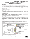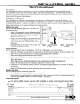
1
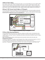
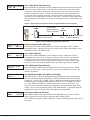
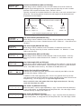
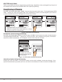
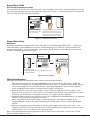
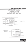
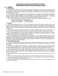
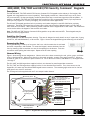
Additional Power Supply
If the current draw for all keypads exceeds the panel output, you can provide additional current by adding a Model
505-12 auxiliary power supply. Connect all keypad common wires to the power supply negative terminal. Run a
jumper wire from the power supply negative terminal to the panel common terminal. Connect all keypad power
(+12 VDC) wires to the power supply positive terminal. Do NOT connect the power supply positive terminal to any
panel terminal. Refer to the 504-24 and 505-12 Power Supply Installation Guide (LT-0453) for more information.
Wiring a 12 VDC Access Control Reader on 793 keypads
To use 12 VDC readers with the 793 keypad, connect the Red and Black power wires from the reader to the power
wires from the panel. These connect in parallel with the keypad power wires. Connect the White data wire from
the reader (Data 1) to the White wire on the 5-wire keypad harness. Connect the Green data wire from the reader
(Data 0) to the Green/White wire on the 5-wire keypad harness.
Green/White – Connect Reader Data 0
White – Connect Reader Data 1
Orange – Door Strike Normally Open
Gray – Door Strike Common
Violet – Door Strike Normally Closed
Yellow/White
1K EOL White/Yellow –
Zone 4
Orange White
1K EOL White/Orange– Zone 3 Request to Exit
Red/White – Zone 2 Door Contact
1K EOL White/Red
1K EOL Brown/White –
White/Brown
Zone 1
Black – Ground
Green – Receive Data
Yellow – Send Data
Red – Keypad Power
Card Reader
To Keypad Bus
Figure 2: 12 VDC Reader Wiring for 793 Keypads
793 Door Strike Relay Specifications
The 793 keypad provides one internal Form C single pole, double throw (SPDT) relay for controlling door strikes
or magnetic locks. Three wires on the 5-wire harness, Violet (N/C), Gray (Com), and Orange (N/O), allow you to
connect devices to the relay. The Form C relay draws up to 30mA of current and its contacts are rated for 1 Amp at
30 VDC maximum.
Note: For UL installations, the door strike relay must be connected to devices within the same room.
Wiring the 333 Suppressor
One Model 333 Suppressor is included with the 793 Keypad. Refer to Figure 3 and install the suppressor across the
5-wire output/reader harness Common (C) and Normally Open (N/O) or Normally Closed (N/C).
����������������
����������
������������
��������
������������
�����������
��������������
�
�
������������������
��������
������
������
���
�
���
���������
����������
�������������
If the device being controlled by the relay is connected to the N/O and C wires, install the suppressor on the N/O
and C wires. If the device is connected to the N/C and C wires, install the 333 Suppressor on N/C and C wires.
��������������
�������������
������
Figure 3: 793 5-wire Harness and Suppressor Installation
Digital Monitoring Products
2
690/690F/790/790F/693/793 Installation Guide