1
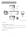
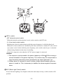
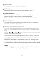
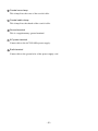
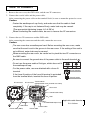
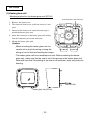
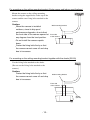
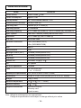
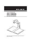
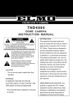
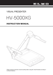
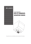
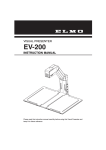
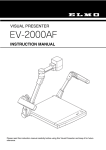
QNW4000
INSTRUCTION MANUAL
CAUTION
RISK OF ELECTRIC SHOCK
DO NOT OPEN
CAUTION : TO REDUCE THE RISK OF ELECTRIC SHOCK.
DO NOT REMOVE COVER (OR BACK).
NO USER SERVICEABLE PARTS INSIDE.
REFER SERVICING TO QUALIFIED SERVICE PERSONNEL.
The lightning flash with arrowhead symbol, within
an equilateral triangle, is intended to alert the user
to the presence of uninsulated "dangerous
voltage" within the product's enclosure that may
be of sufficient magnitude to constitute a risk of
electric shock to persons.
The exclamation point within an equilateral
triangle is intended to alert the user to the
presence of important operating and maintenance
(servicing) instructions in the literature
accompanying the appliance.
CAUTION
.
Do not use any power supply other than
specified.
INFORMATION
This equipment has been tested and found
to comply with the limits for Class A digital
device, pursuant to Part 15 of the FCC
Rules. These limits are designed to
provide reasonable protection against
harmful interference when the equipment
is operated in a commercial environment.
This equipment generates, use, and can
radiate radio frequency energy and, if not
installed and used in accordance with the
instruction manual, may cause harmful
interference to radio communications.
Operation of this equipment in a
residential area is likely to cause harmful
interference in which case the user will be
required to correct the interference at his
own expense.
WARNING
TO REDUCE THE RISK OF FIRE OR
ELECTRIC SHOCK, DO NOT EXPOSE
THIS APPLIANCE TO RAIN OR MOISTURE.
* The CAUTION label is attached on the
bottom of camera.
USER-INSTALLER CAUTION: Your
authority to operate this FCC verified
equipment could be voided if you make
changes or modifications not expressly
approved by the party responsible for
compliance to Part of the FCC Rules.
IMPORTANT SAFETY INSTRUCTIONS
1. Read these instructions.
2. Keep these instructions.
3. Heed all warnings.
4. Follow all instructions.
5. Do not use this apparatus near water.
6. Clean only with dry cloth.
7. Do not block any ventilation openings, install in accordance with the manufacture's
instructions.
8. Do not install near heat sources such a radiators, heat registers, stoves or other
apparatus (including amplifiers) that produce heat.
9. Only use attachment/accessories specified by the manufacturer.
10. Unplug this apparatus during lighting storms or when unused for long periods of
time.
11. Refer all servicing to qualified personnel. Servicing is required when the apparatus
has been damaged in any way, such as power-supply cord or plug is damaged,
liquid has been spilled or objects have been fallen onto the apparatus, the apparatus
has been exposed to rain or moisture, does not operate normally, or has been
dropped.
-1-
Housing Protection
Indoor
Outdoor but under
roof or eaves
Outdoor not under
roof or eaves
Height or blowing
place like steel tower
(Shading cover required)
Caution:
- Do not install this camera at sea, at coast or in coastal area or at any corrosive
gas generating place.
- Since it is not of totally weatherproof specifications, do not install this camera at
any weather-beaten place.
When it is used mounted with the shade for outdoor use (SS-20), the weatherproof
specifications meet the requirements of IP54 (Conformable to IEC/EN 60529).
This camera may be installed outdoors but with restrictions; do not install this
camera at any place open to gusty wind and rain as seen in typhoon (e.g., high steel
tower), to snow (e.g., cold district), to water spray (e.g., coast or coastal area), or to
water (e.g., under the water).
For further information of installation place, consult our dealer.
-2-
PART NAMES AND FUNCTIONS
84 (3.3)
45 (1.8)
14 (0.6)
230 (9.1)
75 (3.0)
84 (3.3 )
84 (3.3)
45 (1.8)
14 (0.6)
All dimensions in mm (inch)
Front glass
Tripod fixing tapped holes (1/4-20UNC)
These tapped holes are used to fix the camera on the tripod and mount the shade (optional) on
the camera.
The tapped holes for fixing the tripod are provided at 2 locations in the top and bottom surface
of the camera. Each tapped hole is 5mm deep.
Weatherproof cap
-3-
INT/LL switch
INT (internal) control switch
When the internal synchronization is used, set the switch to the INT side.
LL (Line-Lock) control switch
Matching the vertical synchronization with the power frequency is called the line-lock.
When two or more cameras are switched by the video switcher to a monitor TV, the vertical
sync. phase can be locked with the power frequency, and a stable vertical sync. is obtained
without being disturbed at the time of switching.
Line-lock is operative only when the AC 24V power supply is connected.
Caution:
1. The camera is synchronized to the power frequency of 60Hz 0.5Hz covering a
normal fluctuation of the power frequency. The camera may not compensate for
large fluctuation caused by power generated by an engine generator. etc.
2. It takes about 10 seconds or more to obtain a stable synchronization after the
power is turned on. This is necessary to stabilize the camera against the power
noise.
BLC (Back Light Control) switch
In case the back lighting is too bright to shoot the main object clearly, set this switch to ON
position.
-4-
SENS-UP switch
To increase the sensitivity, set this switch to ON position.
DAY/NIGHT switch
When the DAY/NIGHT function is used, this switch is turned ON. (See P. 9.)
Camera output terminal
This is an image output terminal. When the camera direction, the field angle or the focal point is
adjusted, a monitor TV or other type display is connected to this terminal.
When a monitor TV is connected to this terminal, remove the 2P connector beforehand.
Level adjusting volume
This volume is used to adjust the brightness of the image. If the lens iris is not appropriate,
adjust the iris with this level adjusting volume.
Vertical sync. phase adjustment potentiometer
Vertical sync. phase adjusting potentiometer is set at the position fully that the delay time of
vertical sync. phase against the phase of power frequency is shortest, when shipped from the
factory.
Select this
up (
) and down (
) button will make the delay time of vertical sync. phase
against the phase of power frequency longer.
Use the function control potentiometer
if the picture image on a monitor TV may flow
when using the camera in combination with other camera(s) controlled by the Line-Lock
synchronization.
In this case, get a proper image by shifting the phase of vertical sync. signal of the camera
against that of the other. If a proper image cannot be obtained even after this adjustment, reset
the potentiometer to its original position, and use the function control potentiometer
of the
other camera to shift the phase of vertical sync. signal of other camera.
Caution:
Before making adjustment, make sure that cameras have their power supplies
connected with the same polarity. (not 180 apart)
-5-
Coaxial core clamp
This clamp fixes the cores of the coaxial cable.
Coaxial cable clamp
This clamp fixes the sheath of the coaxial cable.
Ground terminal
This is a supplementary ground terminal.
AC power terminal
Connect this to the AC24V 60Hz power supply.
Earth terminal
Connect this to the ground wire of the power supply cord.
-6-
HOW TO CONNECT
1. Remove the rear cover, the GND cable, and the two 2P connectors.
2. Connect the coaxial cable and the power cable.
After connecting the power cable on the terminal block, be sure to mount the protective cover.
Caution:
Fasten the weatherproof cap firmly, and make sure that the cable is fixed
completely. If the cap is not fastened firmly, water leak may be caused.
(The appropriate tightening torque: 4.0~4.5N.m)
When connecting the coaxial cable, be sure to remove the 2P connectors.
3. Connect the two 2P connectors and the GND cable.
After connecting the connectors and the cable, mount the rear cover.
Caution:
The rear cover has a weatherproof seal. Before mounting the rear cover, make
sure that the seal is set in the groove in the rear cover. If the setting of the seal is
not sufficient, water leak may be caused.
When mounting the rear cover, be careful not to pinch the two 2P connectors or
the GND cable.
Be sure to connect the ground wire of the power cable to the earth terminal
.
Do not use the power cable of flat type, which does not fit
the weatherproof cap.
For the power cable, use one attached with a force-fit
5.7
terminal.
If the force-fit portion of the force-fit terminal is protruded
from the terminal block, insulate the force-fit portion.
2P connector
force-fit terminal
force-fit portion
Terminal block
2P connector (with protective cover) Coaxial core clamp
Rear cover
Coaxial cable clamp
Seal
Weatherproof cap
GND cable
Power cable (GND)
Coaxial cable
Power cable
-7-
Applicable cable diameter:
5.0~10.0mm
LENS
1. Built-in Lens
This camera is built in with a dedicated varifocal lens.
F: 1.4 f: 2.8mm~5.8mm
2. Lens adjustment
Adjust the field angle of the lens with the zoom ring, and set the focus with the focus ring.
After setting, lock the lens firmly with the focus ring locking knob and the zoom ring locking
knob. (Factory setting: WIDE end / Infinite)
Adjust the iris volume, if necessary, to obtain the appropriate exposure. (See P.5
.)
Caution:
When adjusting the iris of the auto iris lens, open the iris fully in the circumstance
with sufficient light amount of the object beforehand. If the light amount of the
object is not sufficient, a malfunction may occur.
Zoom ring
Focus ring
Camera main unit
Zoom ring locking knob
Focus ring locking knob
Front cover
-8-
Day/Night FUNCTION
This camera is provided with Day/Night function that can detect the brightness of the objects and
automatically switch the color mode / black-and-white mode according to the detected brightness.
This function allows the output of ordinary colored images for the outdoor monitoring during
daylight and the output of black-and-white images for the night monitoring with a lack of sufficient
light volume. Therefore, even at night, this camera can provide monitoring through images with
little noise.
Furthermore, since this function raises the sensitivity in the infrared area, even a dark object can be
imaged more clearly at night when a commercially available infrared lamp is used together. To
make this function enabled, set the Day/Night switch on the rear panel to "ON."
When the Day/Night switch is set to "OFF," the camera operates as an ordinary color camera even
at night.
When the Day/Night switch is set to "ON" and the object becomes gradually brighter as the time
passes like dawn, it may take time to switch from the black-and-white mode to the color mode. As a
result, the image taken in the early morning may be in black and white. However, note that this is
not a malfunction.
The Day/Night function controls the mode switching between the color mode and the black-andwhite mode according to the signal level.
Since the signal level varies depending on the camera settings to shoot the object, the timing of
Day/Night switching varies accordingly.
When more than one screen is displayed by the controller or the like, the Day/Night mode may vary
depending on the camera shooting conditions even if the brightness is the same.
-9-
OPTION
(1) Heater glass unit
Mounting method for the heater glass unit (DF-20)
Connector jack in the main unit
1. Remove the front cover.
2. The removed front cover (with four screws) is not
used.
3. Instead of the front cover removed in the step 2.,
mount the heater glass unit.
4. Insert the connector of the heater glass unit wiring
into the connector jack in the main unit.
5. Mount the heater glass unit.
Caution:
When mounting the heater glass unit, be
careful not to pinch the wiring or bring the
wiring in front of the lens blocking the image.
The heater glass unit has a weatherproof seal. Before mounting the heater
glass unit, make sure that the seal is set in the groove in the heater glass unit.
Note with care that if the setting of the seal is not sufficient, water may leak into
housing.
1.2W (DC15V)
Heater glass unit (DF-20)
- 10 -
(2) Shade (Cover for outdoor use)
Mounting method for the shade (SS-20)
Mount the shade (cover for outdoor use)
firmly over the camera main unit with
the two attached fixing bolts.
Use the tripod fixing tapped holes in the
top of the camera main unit.
Fixing bolt
Through hole
for bolt
Shade
Tripod fixing
tapped hole
Camera
main unit
(3) Fittings
For mounting on the wall mounting bracket (Outdoor specifications)
Mount the camera on the wall mounting
bracket using the tapped holes in the bottom of
the camera and the two fixing bolts attached to
the camera.
Front side
of the camera
Caution:
When the camera is installed
outdoors, since its drip-proof
performance degrades, do not direct
the front side of the camera upward at
any degrees from the level position.
Wall fitting
Do not install the camera upside
down.
Fixing bolt
Fasten the fixing bolts firmly so that
the camera cannot come off and drop
due to looseness.
Insulating spacer
- 11 -
For mounting on the ceiling mounting bracket (Under eaves and indoor specifications)
Mount the camera on the ceiling mounting
bracket using the tapped holes in the top of the
camera and the two fixing bolts attached to the
camera.
Caution:
Wall mounting bracket
When the camera is installed
outdoors, since its drip-proof
performance degrades, do not direct
the front side of the camera upward at
any degrees from the level position.
Front side
of the camera
Do not install the camera upside
down.
Fasten the fixing bolts firmly so that
the camera cannot come off and drop
due to looseness.
For mounting on the ceiling mounting bracket together with the shade (SS-20)
Use the fixing bolts attached to the shade.
(Do not use the fixing bolts attached to the
camera.)
Caution:
Fasten the fixing bolts firmly so that
the camera cannot come off and drop
due to looseness.
Wall mounting bracket
Front side
of the camera
Shade
(SS-20)
- 12 -
TROUBLESHOOTING
Symptom
Image is not seen.
Check point
Is the iris of the lens adjusted appropriately?
Are the cables connected correctly?
Are the power plugs of the peripheral units inserted firmly in the
outlet?
Image is not colored.
When Day/Night function is set to "ON" and the object is dark, the
image is in black and white.
Image is not colored
accurately.
Is the video monitor adjusted appropriately?
Isn't the light dark with the Day/Night function set to "OFF"?
- 13 -
SPECIFICATIONS
QNW4000
Model
Power source
AC24V 60Hz 0.5Hz
Power consumption
Approx. 5.0w
Pick-up device
1/4" Color interline-transfer CCD
Effective picture element
768 (H) X 494 (V)
Scanning area
3.65mm (H) X 2.74mm (V)
Scanning system
2:1 interlaced
Scanning frequency
LL:15.75kHz (H), 60Hz (V) / INT:15.734kHz (H), 59.94Hz (V)
Sync. system
Line-Lock / Internal (Factory-set at Line-Lock)
Resolution
470 TV lines (H), 350 TV lines (V)
S/N ratio
More than 48dB
Minimum illumination
1.5lx (DAY/NIGHT:OFF)
0.3lx (DAY/NIGHT:ON)
AGC
Built-in
White balance
ATW
Backlight control (BLC)
Provided (Factory-set at OFF)
Sens-up
Provided (Factory-set at OFF)
Day/Night
Provided (Factory-set at ON)
Monitor out
RCA VBS 1V (p-p) 75
Iris
DC system
Iris level adjustment
Provided
Lens
1/4" vari-focal lens
F: 1.4 f: 2.8~5.8
Weatherproof specifications IP54 (When outdoor shade is used)
Dimensions
84 (W) X 75 (H) X 230 (D) mm (3.3 X 3.0 X 9.1 inches)
Weight
1.2kg (2.6lbs)
Ambient temperature
-10
~50
Ambient humidity
30
~ 90
Supplied accessories
Instruction manual
Warranty card
Tripod screws
(14 F~122 F)
Note: Weight and dimensions are approximate.
Design and specifications are subject to change without prior notice.
- 14 -
PRECAUTIONS FOR USE AND INSTALLATION
* Never aim the camera at the sun.
Never aim or point the camera at the sun even
if you are not shooting.
* Do not shoot intense light.
Strong light such as a spot light on the image
plane will cause blooming or smear. When
strong light comes into the image plane,
vertical stripes may appear on it. However,
this does not mean that the camera is defect.
* Take precautions when handling a camera.
Do not drop your camera, or give it a strong
shook or vibration. This may cause camera to
malfunction.
* Do not touch internal parts.
Be sure not to touch the internal parts. This
may cause to electrical shock.
* Do not let the camera get wet.
Install the camera at the place where it will
not get wet.
Should it gets wet, turn off the power
immediately and contact your dealer.
* Install your camera where no video noise
appears.
When camera cables have been laid near
electric wires or television receivers, a noise
may interfere the image.
If noise occurs, relocate cables or reinstall
equipment.
* Check the ambient temperature and humidity.
Avoid using camera in areas where
temperature is consistently hotter or colder
than the specified range (See Specifications
chart below) or poor image quality or
damaged parts may occur. Precautions should
also be taken to avoid areas of high humidity.
* Should you notice any trouble.
If any trouble occurs while you are using the
camera, turn off the camera and contact your
dealer. Failure to do so may cause damage to
the camera.
* The socket-outlet should be installed near the
equipment and should be easily accessible.
ELMO CO., LTD.
6-14, Meizen-cho, Mizuho-ku,
Nagoya, 467-8567 Japan
OVERSEAS SUBSIDIARY COMPANIES
ELMO Mfg. Corp.
ELMO Canada Mfg. Corp.
ELMO (Europe) G.m.b.H.
1478 Old Country Road,
Plainview, NY 11803-5034
U.S.A.
Tel. 516-501-1400
Fax. 516-501-0429
E-mail:[email protected]
Web:http://www.elmousa.com
44 West Drive, Brampton,
Ontario, L6T 3T6,
Canada
Tel. 905-453-7880
Fax. 905-453-2391
E-mail:[email protected]
Neanderstr. 18
40233 Dusseldorf,
Germany
Tel. 0211-376051-53
Fax. 0211-376630
E-mail:[email protected]
6X1NRNA02
Printed in Japan
- 15 -