1
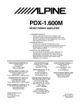
OPERATORS MANUAL·
-,.
---.
~
-.
--;
-_.-
...... .
MARINE DIESEL ENGINES
-
. --. -
---• ."-~-~~-- -
-----..--=---::..-:-::.--
-
~
._-_.------------
-.
~-
.. - -.. -
-
.65A- FOUR~!AND 658 -F·OUR
REVISION 2
JUNE
2011
<
WESTERBEKE'
.
WESTERBEKE CORPORATION' MYLES STANDISH INDUSmlAL PARK
150 JOHN HANCOCK ROAD, TAUNTON, MA 02780-7319' TEL. 1-508·823-7677
FAX 1-508 884-9688' WEBSITE: www.WESTERBEKECOM
'.
'..,;,.,~
---
..
-
_.
.
NMMA Member National Marine Manufacturers Association
-
A WARNING
Exhaust gasses contain Carbon Monoxide, an odorless and
colorless gas. Carbon Monoxide is poisonous and can cause
unconsciousness and death. Symptoms of Carbon Monoxide
exposure can include:
-Dizziness
- Throbbing in Temples.
-Nausea
- Muscular 7Ivitching
-Headache
- Vomiting
- Weakness and Sleepiness -Inability to Think Coherently
IF YOU OR ANYONE ELSE EXPERIENCE ANY OF THESE SYMPTOMS,
GET OUT INTO THE FRESH AIR IMMEDIATELY. If symptoms persist,
seek medical attention. Shut down the unit and do not restart
until it has been inspected and repaired.
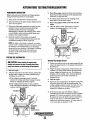
A WARNING DECAL is provided by
WESTERBEKE and should be fixed to a
bulkhead near your engine or generator.
WESTERBEKE also recommends installing
CARBON MONOXIDE DETECTORS in the
living/sleeping quarters of your vessel.
Theyare inexpensive and easily
obtainable at your local marine store.
PROPOSITION 65 WARNING
Marine diesel and gasoline engine
exhaust and some of its constituents
are known to the State of California
to cause cancer, birth defects,
and other reproductive harm.
SAFETY INSTRUCTIONS
PREVENT BURNS - FIRE
INTRODUCTION
Read this safety manual carefully. Most accidents are
caused by failure to follow fundamental rules and
precautions. Know when dangerous conditions exist and
take the necessary precautions to protect yourself, your
personnel, and your machinery.
The following safety instructions are in compliance with
the American Boat and Yacht Council (ABYC) standards.
A WARNING: Fire can cause injury or death!
• Prevent flash fires. Do not smoke or permit flames or
sparks to occur near the carburetor, fuel line, filter, fuel
pump, or other potential sources of spilled fuel or fuel
vapors. Use a suitable container to catch all fuel when
removing the fuel line, carburetor, or fuel filters.
• Do not operate with a Coast Guard Approved flame
arrester removed. Backfire can cause severe injury or
death.
• Do not operate with the air cleaner/silencer removed.
Backfire can cause severe injury or death.
• Do not smoke or permit flames or sparks to occur near
the fuel system. Keep the compartment and the
engine/generator clean and free of debris to minimize the
chances of fire. Wipe up all spilled fuel aud engine oil.
• Be aware - diesel fuel will bum.
PREVENT ELECTRIC SHOCK
A WARNING: Do not touch AC electrical connections
while engine is running, or when connected to shore
power. Lethal voltage is present at these connections!
•
Do not operate this machinery without electrical
enclosures and covers in place.
• Shut off electrical power before accessing electrical
equipment.
• Use insulated mats whenever working on electrical
equipment.
• Make sure your clothiug aud skin are dry, not damp
(particularly shoes) when handling electrical equipment.
• Remove wristwatch and all jewelry when working on
electrical equipment.
• Do not connect utility shore power to vessels AC
circuits, except through a ship-to-shore double throw
transfer switch. Damage to vessels AC generator may
result if this procedure is not followed.
• Electrical shock results from haudling a charged capaci. tor. Discharge capacitor by shorting terminals together.
PREVENT BURNS -' EXPLOSION
A WARNING: Explosions from fuel vapors can cause
injury or death!
• Follow re-fueling safety instructions. Keep the vessels
hatches closed when fueling. Open and ventilate cabin
after fueling. Check below for fumes/vapor before
running the blower. Run the blower for four minutes
before starling your engine.
• All fuel vapors are highly explosive. Use extreme care
when handling aud storing fuels. Store fuel in a wellventilated area away from spark-producing equipment
and out of the reach of children.
.• Do not fill the fuel tank(s) while the engine is running.
• Shut off the fuel service valve at the engine when servicing
the fuel system. Take care in catching any fuel that might
spill. DO NOT allow any smoking, open flames, or other
sources of fire near the fuel system or engine when servicing. Ensure proper ventilation exists when servicing the
fuel system.
• Do not alter or modify the fuel system.
• Be sure all fuel supp,lies have a positive shutoff valve.
• Be certain fuel line fittings are adequately tightened and
free of leaks.
• Make sure a fire extinguisher is installed nearby and is
properiy maintained. Be familiar with its proper use.
Extinguishers rated ABC by the NFPA are appropriate
for all applications encountered in this environment.
PREVENT BURNS - HOT ENGINE
A WARNING: Do not touch hot engine parts or
exhaust system components. Arunning engine gets
very hot!
•
Always check the engine coolant level at the coolant
recovery tank.
A WARNING: Steam can cause injury or death!
•
In case of an engine overheat, allow the engine to cool
before touching the engine or checking the coolant.
~
WESTERBEKE
Engines & Generators
i
SAFETY INSTRUCTIONS
ACCIDENTAL STARTING
TOXIC EXHAUST GASES
A WARNING: Accidental starting can cause injury
A WARNING: Carbon monoxide (CO) is a deadly gas!
or death!
•
Disconnect the battery cables before servicing the engine!
generator. Remove the negative lead first and reconnect
it last.
• Make certain all personnel are clear of the engine before
starting.
• Make certain all covers. guards, and hatches are reinstalled before starting the engine.
BATTERY EXPLOSION
A WARNING: Battery explosion can cause injury
or death!
• Ensure that the exhaust system is adequate to expel gases
discharged from the engine. Check the exhaust system
regularly for leaks and make sure the exhaust manifold!
water-injected elbow is securely attached.
• Be sure the unit and its surroundings are well ventilated.
Run blowers when running the generator set or engine.
• Don't run the generator set or engine unless the boat is
equipped with a functioning marine carbon monoxide
detector that complies with ABYCA-24. Consult your boat
builder or dealer for installation of approved detectors.
• For additional information refer to ABYC T-22
(educational information on Carbon Monoxide).
A WARNING: Carbon monoxide {CO} is an Invisible
•
Do not smoke or allow an open flame near the battery
being serviced. Lead acid batteries emit hydrogen, a
highly explosive gas, which can be ignited by elect;ical
arcing or by lit tobacco products. Shut off all eleclncal
equipment in the vicinity to prevent electrical arclOg during servicing.
• Never connect the negative (-) battery cable to the positive (+) connection tenninal of the starter solenoid. Do
not test the battery condition by shorting the terminals •
together. Sparks could ignite batt~l{' gases o~ fuel vapors.
Ventilate any compartment contalOmg battenes to prevent
accumulation of explosive gases. To avoid sparks, do not
disturb the battery charger connections while the battery
is being charged.
• Avoid contacting the tenninals with tools, etc., to prevent
bums or sparks that could cause ~ explosion. Remo~e
wristwatch, rings, and any other Jewelry before handllOg
the battery.
• Always tum the battery charger off before disconnecting
the battery connections. Remove the negative lead first
and reconnect it last whenservicing the battery.
odorless gas. Inhalation produces "u-like symptoms,
nausea or death!
• Do not use copper tubing in diesel exhaust systems. Diesel
fumes can rapidly destroy copper tubing in exhaust systems.
Exhaust sulfur causes rapid deterioration of copper tublOg
resulting in exhaust/water leakage.
• Do not install exhaust outle,t where exhaust can be drawn
through portholes, vents, or air conditione~s. If the engine
exhaust discharge outlet is near the waterline, water could
enter the exhaust discharge outlet and close or restrict the
flow of exhaust. Avoid overloading the craft.
• Although diesel engine exhaust gases are not as toxic as
exhaust fumes from gasoline engines, carbon monoxide
gas is present in diesel exhaust fume~. S?me o~ the
symptoms or signs of carbon monmade mhalatlOn or
poisoning are:
Vomiting
Inability to think coherently
Throbbing in temples
Dizziness
Muscular twitching
Headache
Wealrness and sleepiness
Nausea
BATTERY ACID
AVOID MOVING PARTS
A WARNING: Sulfuric acid in batteries can cause
A WARNING: Rotating parts can cause injury
severe injury or death!
or death!
• When servicing the battery or checking the electrolyte
level, wear rubber gloves, a rubber apron, and eye protection. Batteries contain sulfuric acid which is destructive.
If it comes in contact with your skin, wash it off at once
with water. Acid may splash on the skin or into the eyes
inadvertently when removing electrolyte caps.
~
• Do not service the engine while it is running. If a situation
arises in which it is absolutely necessary to make operating adjustments, use extreme care to avoid touching mov~
ing parts and hot exhaust system components.
WESTERBEKE
Engines & Generators
ii
SAFETY INSTRUCTIONS.
•
Do not wear loose clothing or jewelry when servicing
equipment; tie back long hair and avoid wearing loose
jackets, shirts, sleeves, rings, necklaces or bracelets that
could be caught in moving parts.
• Make sure all attaching hardware is properly tightened.
Keep protective shields and guards in their respective
places at all times.
• Do not check fluid levels or the drive belt's tension while
the engine is operating.
• Stay clear of the drive shaft and the Iransruission coupling
when the engine is running; hair and clothing can easily
be caught in these rotating parts.
HAZARDOUS NOISE
A WARNING: High noise levels can cause hearing
loss!
•
•
Never operate an engine without its muffler installed.
Do not run an engine with the air intake (silencer)
removed.
• Do not run engines for long periods with their enclosures
open.
A WARNING: Do not work on machinery when you are
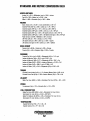
ABYC, NFPA AND USCG PUBLICATIONS FOR
INSTALLING OIESEL ENGINES
Read the following ABYC, NFPA and USCG publications
for safety codes and standards. Follow their recommendations when installing your engine.
ABYC (American Boat and Yacht Council)
"Safety Standards for Small Craft"
Order from:
ABYC
3069 Solomon's Island Rd.
Edgewater, MD 21037
NFPA (National Fire Protection Association)
"Fire Protection Standard for Motor Craft"
Order from:
NFPA
II Tracy Drive
Avon Industrial Park
Avon, MA 02322
USCG (United States Coast Guard)
"USCG 33CFR183"
Order from:
U.S. Government Printing Office
Washington, D.C. 20404
mentally or physically Incapacitated by fatigue!
OPERATORS MANUAL
Many of the preceding safety tips and warnings are repeated
in your Operators Manual along with other cautions and
notes to highlight critical infonnation. Read your manual
carefully, maintaln your equipment, and follow all safety
procedures.
ENGINE INSTALLATIONS
Preparations to .install an engine should begin with a thorough exaruination of the American Boat and Yacht Council's
(ABYC) standards. These standards are a combination of
sources including the USCG and the NFPA.
Sections of the ABYC standards of particular interest are:
H-2 Ventilation
P-I Exhaust systems
P-4 Inboard engines
E-9 DC Electrical systems
All installations must comply with the Federal Code of
Regulations (FCR).
~
WESTERBEKE
Engines & Generators
iii
· INSTALLATION
When installing WESTERBEKE engines and generators it is important that strict
attention be paid to the following information:
CODES AND REGULATIONS
Strict federal regulations, ABYC guidelines, and safety codes must be complied with
when installing engines and generators in a marine environment.
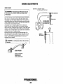
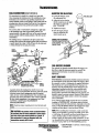
SIPHON·BREAK
For installations where the exhaust manifold/water injected exhaust elbow is close to
or will be below the vessel's waterline, provisions must be made to install a siphonbreak in the raw water supply hose to the exhaust elbow. This hose must be looped a
minimum of 20" above the vessel's waterline. Failure to use a siphon.breakwhen
the exhaust manifold injection port is at or below the load waterline wl7l result in
raw water damage to the engine and possible flooding of the boat.
If you have any doubt about the position of the water-injected exhaust elbow relative
to the vessel's waterline under the vessel's various operating conditions, install a
siphon·break.
NOTE: A siphon-break requires periodic inspection and cleaning to ensure proper
operation. Failure to properly maintain a siphon-break can· result in catastrophic
engine damage. Consult the siphon-break manufacturer for proper ·maintenance.
EXHAUST SYSTEM
The exhaust bose must be certified for marine use. The system must be designed to
prevent water from entering the exhaust under any sea conditions and at any angle
of the vessels hull.
Adetailed Marine Installation Manual covering gasoline and diesel,
engine and generators is supplied with each unit. Apdf copy is
available to download from our website at www.westerbelre.com.
'"tIY'
WESTERBEKE
Engines & Generators
iv
~V~ILABLE FROM
YOUR WESTERBEKE
OE~LER
TABLE OF CONTENTS
Parts Identification (Illustrations) .................................2
Introduction .......................................................................3
Serial Number Location .............................................. .4
Ordering Parts ............................................................ ..4
Control Panel (Admiral) ...................................................5
Control Panel (Captain) ...................................................6
Diesel Fuel, Engine Oil and Engine Coolant ...............7
Tachometer ......................................................................27
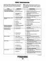
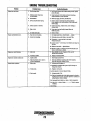
Engine Troubleshooting .................................................28
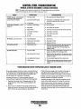
Control Panel Troubleshooting ....................................30
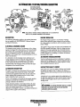
Alternator Troubleshooting .......................................... .31
Troubleshooting .......................................................... 31
Testing ....................................................................... .32
Checking/Servicing Battery ...................................... .33
Battery Care .............................................................. .33
Coolant Recovery Tank ................................................ 7
Dual Output Alternators ................................................34
Troubleshooting ......................................................... .35
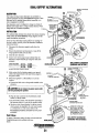
High Output Alternators ................................................36
Starter Motor...................................................................37
Troubleshooting ......................................................... .37
ZF Transmissions ............................................................39
Preparations for I.nitial Start... .......................................8
Pre-start Inspection ....................................................... 8
Starting/Stopping Procedure ..........................................9
Warning Lights, Alarms & Circuit Breaker ................ 10
Maintenance Schedule .................................................. 11
Cooling Circuit ................................................................13
Raw Water Intake Strainer ...... ,.................................. 13
Draining the Raw Water System ................................ 13
Thennostat. ................................................................. 14
Fresh Water Circuit .................................................... 15
Changing Coolan!... .................................................... 15
Raw Water Pump ........................................................ 16
Heat Exchanger .......................................................... 16
Water Heater ............................................................... 17
Fuel System ..................................................................... 18
Fuel Filter ................................................................... 18
Fuel Water Separator .................................................. 18
Engine L~bricating Oil .................................................. 19
Oil Change ................................................................. 19
Remote Oil Filter ............................................................20
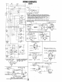
W'niO"
ng lagram ...............................................................21
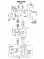
Wiring Schematic ...........................................................22
Engine Adjustments .......................................................23
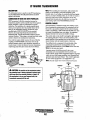
Change the Fluid ........................................................ 39
Specifications ............................................................. 39
Control Cables ........................................................... .40
Transmission Cooler................................................... 41
Maintenance ............................................................... 41
ZF Transmissions (H8W Models) ................................ .42
Change the Fluid ....................................................... .43
Maintenance ...............................................................43
Velvet Drive Transmissions ..........................................44
Change the Fluid ....................................................... .45
Troubleshooting ..•...................................................... .46
Oil Coolers ..•.•.0 ••••••••••••••••••••••••••••••••••••••••••••••••••••••••• .46
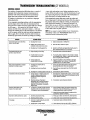
Transmission Troubleshooting ,ZF ..... ".,., ..... ,." .. ,., ... ,..47
_ COllli""! Ca!Jles ..:., .. " ................... :.............................. .48
. Specifications .......................................:............... :......... ~9 ...
Lay.Up an dRecommlsslonmg
. " " ......................................51.
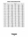
Metric Conversion Data ................................................53
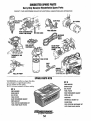
Suggested Spare Parts ..................................................54
Fuel Injectors ......................................................... ~ .... 23
Glow Plugs ................................................................. 24
Valve Clearance Adjustment ...................................... 25
Drive Belt Adjustment ............................................... 26
Testing Oil Pressure ................................................... 26
Engine Compression .................................................. 26
~
WESTERBEKE
Engines & Generators
1
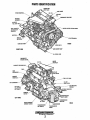
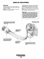
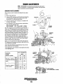
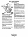
PARTS IDENTIFICATION
CRANK CASE
VALVE
ANODE
INTAKE '''",lItULU,
THERMOSTAT ASSEMBLY
PRE-HEAT
I
ELECTRIC
FUEL SHU'T-OFIB;;;;:JJ:::~:J~:Qj
WATER HEATER CONNECTIONS
AND SHUT-OFF
BRACKETS
SPIN-ON
ALTERNATOR
FRONT
INJECTION
JI::;;;Y--"""""''''<D PUMP
RIGHT SIDE
OIL DRAIN HOSE
THERMOSTAT
HOUSING COVER
INTAKE
MANIFOLD
COOLANT PRESSURE CAP
HEAT
EXCHANGER~._ _ _~
EXHAUST
FUEL LIFT PUMP
DC ALTERINATOR ---------1~.
IN-LINE
::;~~'S::~Dt+----FUEL FILTER
""j:;:::Si1;-----:~~PRESSURE
LEFT SIDE
OIL DIPSTICK
(OPTIONAL) ,
~~~~_//;;;:~ !!:
P
SENO'ER
~
;;,;-,;;;~~;;-ISOLATED
LEFT SIDE
OIPSTICK
',,,erTe,,'
WATER
EXHAUST ELBOW
TRANSMISSION
TRANSMISSION
DRAIN
OIL COOLER
2
REAR
INTRODUCTION
This WESTERBEKE Engine is a product of
WESTERBEKE'S long years of experience and advanced
technology. We take great pride in the superior durability and
dependable performance of our engines and generators.
Thank you for selecting WESTERBEKE.
In order to get the full use and benefit from your engine, it is
important that you operate and maintain it correctly. This
manual is designed to help you do this. Please read this
manual carefully and observe all the safety precautions
throughout. Should your engine require servicing, contact
your nearest WESTERBEKE dealer for assistance.
This is your Operators Manual. A Service Manual wili also
be available from your WESTERBEKE dealer. If you are
planning to install this equipment contact yourself, contact
your WES1ERBEKE dealer for WESTERBEKE'S
Installation Manual.
Customer Identification Card
WES1ERBEKE customers should also keep in mind the time
span between printings of WES1ERBEKE product
software and the unavoidable existence of earlier
WES1ERBEKE manuals. In summation, product software
provided with WESTERBEKE products, whether from
WES1ERBEKE or other suppliers, must not and carmot
be relied upon exclusively as the definitive authority on
the respective product. It not only makes good sense
but is imperative that appropriate representatives of
WESTERBEKE or the supplier in question be consulted
to determine the accuracy and currentness of the
product software being consulted by the customer.
NOTES, CAUTIONS AND WARNINGS
As this manual takes you through the operating procedures,
maintenance schedules, and troubleshooting of your marine
engine, critical infonnation wili be highlighted by NOTES,
CAUTIONS, and WARNINGS. An explanation follows:
NOTE: An operating procedure essential to note.
,WESTERBEKE
''''''"
, Engines & Generators
A CAUTION: Procedures, which if not strictly observed,
Customer Identification
WESTERBEKE OWNER
MAIN STREET
HOMETOWN, USA
Model
Ser.#
Expires
can result In the damage or destruction of your engine.
A WARNING: Procedures, which if not properly fDIIDwed,
can result in personal injury Dr loss Df life.
PROTECTING YOUR INVESTMENT
WARRANTY PROCEDURES
Your WES1ERBEKE Warranty is included in a separate
folder. If, you have not received a customer identification
card registering your warranty 60 days after submitting the
Warranty Registry form, please contact the factory in
writing with model information, including the unit's serial
number and commission date.
PRODUCT SOFTWARE
Product software, (tech data, parts lists, manuals,
brochures and catalogs), provided from sources other than
WES1ERBEKE are not within WES1ERBEKE's control.
",yo
Care at the factory during assembly and thorough testing have
resulted in a WESTERBEKE engine capable of many thousands
of hours of dependable service. However, the manufacturer cannot control how or where the engine is installed in the vessel or
the marmer in which the unit is operated and serviced in the field.
This is up to the buyer/owner-operator.
NOTE: Six important steps to ensure a long engine/generator life.
• Proper engine installation.
• An efficient, well-designed exhaust system that includes an
anti-syphon break to prevent water from entering the engine.
• Changiug the engine oil every 250 operating hours.
• Proper maintenance of all engine components according to the
mainteuance schedule in this manual.
• Use clean, filtered diesel fuel
• Winterize your engine according to the LAY-UP AND
RECOMMISSIONING section in this manual.
WESTERBEKE
Engines & Generators
3
INTRODUCTION
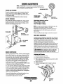
SERIAL NUMBER LOCATION
ORDERING PARTS
The engine's model number and serial number are located on
the namepiate mounted on the side of the engine's water
jacketed exhaust manifold. The engine's serial number is
stamped in the engine block on the right rear side just above
the side oil fill. Enter this information on the illustration of
the nameplate below. Use it for a quick reference when needed.
Whenever replacement parts are needed, always provide the
engine model number and engine serial number as they
appear on the silver and black name plate located on the
martifold. You must provide us with this information so we
may properly identify your engine. In addition, include a
complete part description and part number for each part
needed (see the separately furnished Parts List). Insist upon
WESTERBEKE packaged parts because will fit or generic
parts are frequently not made to the same specifications as
original equipment.
SPARES AND ACCESSORIES
Certain spares will be needed to support and maintain your
WESTERBEKE engine. Your local WES1ERBEKE dealer
will assist you in preparing an inventory of spare parts. See
the SPARE PARTS page in this manual. For engine
accessories, see WESTERBEKE'S ACCESSORIES brochure.
Fill in the information for your referanee.
UNDERSTANDING THE DIESEL ENGINE
The diesel engine closely resembles the gasoline engine,
since the mechanism is essentially the same. The cylinders
are arranged above a closed crankcase. The crankshaft is the
same general type as that of a gasoline engine, and the diesel
engine has the same types of valves, camshaft, pistons,
connecting rods and lubricating system.
Therefore, to a great extent, a diesel engine requires the
same preventive maintenance as a gasoline engine. The
most important factors are proper ventilation and proper
maintenance of the fuel, lubricating and cooling systems.
Fuel and lubricating filler elements must be replaced at the
time periods specified and frequent checking for
contaminations (water, sediment, etc.) in the fuel system is
also essential. Another important factor is the use of the same
brand of high detergent diesel lubrication oil designed
specifically for diesel engines.
The diesel eugine does differ from the gasoline engine,
however, in its method of handling and firing of fuel. The
carburetor and ignition systems are replaced by a single
component - the fuel injection pump - which performs the
function of both.
~
WESTERBEKE
Engines & Generators
4
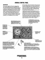
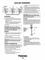
ADMIRAL CONTROL PANEL
DESCRIPTION
When the engine is shut down with the key switch turned off,
the water temperature gauge will continue to register the last
temperature reading indicated by the gauge before elecmcal
power was turned off. The oil pressure gauge will fall to zero
when the key switch is turned off. The temperature gauge
will once again register the engine's true temperature when
elecmcal power is restored to the gauge.
A separate alarm buzzer with harness is supplied with every
Admiral Panel. The installer is responsible for elecmcally connecting the buzzer to the four-pin connection on the engine's
elecmcal harness. The installer is also responsible for installing
the buzzer in a location where it will be dry and where it will
be audible to the operator should it sound while the engine is
running. The ·buzzer will sound when the ignition key is turned
on arid should silence when the engine has started and t\je
engine's oil pressure rises above 15 psi (1.1 kg/em').
This manually-operated control panel is equipped with a
KEY switch and RPM gauge with an ELAPSED TIME
meter which measures the engine's running time in hours and
in 1/10 hours. The panel also includes a WAlER TEMPERAWRE gauge which indicates water temperature in degrees
Fahrenheit, an OIL PRESSURE gauge which measures the
engine's oil pressure in pounds per square inch, and a DC
control circuit VOLTAGE gauge which measures the system's voltage. All gauges are illuminated when the key
switch is turned on and remain illuminated while the engine
is in. operation. The panel also contains two rubber-booted
pushbuttons, one for PREHEAT and one for START.
OIL PRESSURE GAUGE: THIS GAUGE IS GRADU·
ATED IN POUNDS PER SQUARE INCH (PSI) AND IS
ILLUMINATED WHILE THE KEY SWITCH IS TURNED
ON. THE ENGINE·S NORMAL OPERATING OIL
PRESSURE RANGES BETWEEN 30 - 60 psi
(2.1 - 4.2 kg/em').
.
WATER TEMPERATURE GAUGE: THIS GAUGE IS
GRADUATED IN DEGREES FAHRENHEIT AND IS
ILLUMINATED WHILE THE KEY SWITCH IS
TURNED ON. THE ENGINE·S NORMAL OPERATING
TEMPERATURE IS 170" -190" Ftn"-R/'"r.'.
RPM GAUGE: REGIS·
TERS REVOLUTIONS
PER MINUTE OFTHE
ENGINE AND CAN BE
RECALIBRATED FOR
ACCURACY FROM THE
REAR OF THE PANEl.
HDURMETER: ~m--REGISTERS ELAPSED
TIME, AND SHOULD BE
USED AS A GUIDE FOR
THE MAINTENANCE
SCHEDULE.
__
~
~
~
START BUTTON: WHEN PRESSED, ENERGIZES THE
STARTER'S SOLENOID WHICH CRANKS THE ENGINE.
THIS BUTTON WILL NOT OPERATE ELECTRICALLY
UNLESS THE PREHEAT BUTTON IS PRESSED AND HELD
AT THE SAME TIME.
:
"
.-••"
~
VOLTMETER:
INDICATES THE AMDUNTTHE
BAm~Y IS BEING CHARGED.
SHOULD SHOW 13VTD 14V.
AUTOMATIC ALARM SYSTEM
COOLANT TEMPERATURE ALARM: AN ALARM BUZZER HAS BEEN
SUPPLIED WITH THE INSTRUMENT PANEl. IF THE ENGINE'S COOLANT
REACHES 210' F(99'C), THIS SWITCH WILL CLOSE SOUNDING THE
ALARM WHICH WILL EMIT A CONTINUOUS SIGNAl.
OIL PRESSURE ALARM: AN OIL PRESSURE ALARM SWITCH IS
LOCATED OFFTHE ErfGINE'S OIL GALLERY. THIS SWITCH MONITORS
THE ENGINE'S OIL PRESSURE. SHOULD THE ENGINE'S OIL PRESSURE
FALL TO 5 -10 psi (0.4 -0.7 kg/em'), THE SWITCH WILL CLOSE SOUND·
ING THE ALARM. IN THIS EVENT, THE ALARM WILL EMIT A PULSATING
SIGNAl.
Engine~
& Generators
5
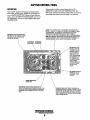
CAPTAIN CONTROL PANEL
DESCRIPTION
The panel also includes an alarm buzzer. for low OIL
PRESSURE or high COOLANT TEMPERATURE. The
RPM gauge is illuminated when the KEY switch is turned oil
and remains illuminated while the engine is in operation.
This manually-operated control panel is equipped with a
KEY switch, an RPM gauge, PREHEAT and START buttons, an INSTRUMENT TEST button and three indicator
lamps, one for ALTERNATOR DISCHARGE, one for low
OIL PRESSURE, and one for high ENGINE COOLANT
TEMPERATURE.
ALARM: THE ALARM WILL SOUND If THE ENGINE'S OIL PRESSURE fALLS
BELOW 5 -10 psi (0.4 - 0.7 kg/em'). IN THIS EVENT, THE ALARM WILL EMIT A
PULSATING SIGNAL THE ALARM WILL ALSO SOUND If THE COOLANT
TEMPERATURE IN THE fRESHWATER COOLING CIRCUIT RISES TO
210'f (99'C). IN THIS EVENT, THE ALARM WILL EMIT A CONTINUOUS SIGNAL.
NOTE: THE ALARM WILL SOUND WHEN THE KEY SWITCH IS TURNED ON. THIS
SOUNDING IS NORMAL. ONCE THE ENGINE STARTS AND THE ENGINE'S OIL
PRESSURE REACHES 15 psi (1.1 kg/em'), THE ALARM WILL SILENCE
RPM GAUGE: REGISTERS REVOLUTIONS
PER MINUTE Of THE ENGINE AND CAN BE
RECALIBRATED fOR ACCURACY fROM
THE REAR Of THE
TEST BUTTON: WHEN
PRESSED, TESTS THE
ALTERNATOR, THE OIL
PRESSURE, AND THE
COOLANTTEMPERATURE CONTROL CIRCUITS. WHEN PRESSED,
THE ALTERNATOR, THE
OIL PRESSURE, AND
THE WATER TEMPERA·
TURE INOICATOR
LIGHTS ILLUMINATE IN
ADDITION TO SOUND·
ING THE ALARM
BUZZER,
~--- .,," SWITCH: PROVIDES
POWER ONLYTO THE
INSTRUMENT PANEL
CLUSTER.
WATER TEMPERIITUFIE /
ALARM LIGHT
START BUTTON: WHEN PRESSED, ENERGIZES THE
STARTER'S SOLENOID WHICH CRANKS THE ENGINE, THIS
BUTTON WILL NOT OPERATE ELECTRICALLY UNLESS THE
PREHEAT BUTTON IS PRESSED AND HELD ATTHE SAME
TIME.
Engines & Generators
6
'PR'FHFI'T R11TTO,N' WHEN PRESSED, ENERGIZES THE
ALTERNATOR'S EXCITER, THE fUEL LIfT PUMP, THE FUEL
SOLENOID ON THE INJECTION PUMP, ANO THE ENGINE'S
GLOW PLUGS, AND BYPASSES THE ENGINE'S OIL PRESSURE ALARM SWITCH. IN ADDITION, THIS BUTTON ENERGIZES THE START BUTTON,
DIESEL FUEL, ENGINE OIL AND ENGINE COOLANT
DIESEL FUEL
ENGINE COOLANT
Use a diesel fuel that meets the requirements of No. 2-D
SAE J 313 and has a Cetane rating of #45 or higher grade of
diesel fuel according to ASTM D975
WESTERBEKE recommends a mixture of 50% antifreeze
and 50% distilled water. Distilled water is free from the
chemicals that can corrode internal engine surfaces.
The antifreeze performs double duty. It allows the engine to
run at proper temperatures by transferring heat away from
the engine to the coolant, and lubricates and protects the
cooling circuit from rust and corrosion. Look for a good
quality antifreeze that contains Supplemental Cooling
Additives (SCAs) that keep the antifreeze chemically
balanced, crucial to long term protection.
The distilled water and antifreeze should be premixed before
being poured into the cooling circuit.
Care Of The Fuel Supply
Use only clean diesel fuel! The clearance of the components
in your engines fuel injection pump is very critical; invisible
dirt particles which might pass through the primary and secondary filters can damage these finely machined parts. It is
important to buy clean fuel, and keep it clean. The best fuel
can be rendered unsatisfactory by careless handling or
improper storage facilities. To ensure that the fuel going into
the tank for your engine's daily use is clean and pure, the
following practice is advisable:
Purchase a well-known brand of fuel. The use of additives
to combat BACTERIAL growth in the fuel tank is
recommended such as Bio-Bar and an additive such as
Diesel Kleen + Centane Boost to help restore lubricity back
into the diesel fuel when an Ultra Low Sulfur diesel is being
used.
Install and regularly service a good, visual-type fuel
filter/water separator between the fuel tank and the engine.
The Raycor 500 MA or 230 RMAM are good examples of
such filters. A 10 micron filter element is recommended.
NOTE: Look for the new environmentallyjriendly long lasting
antifreeze that is now available.
PURCHASING ANTIFREEZE
Rather than preparing the mixture, WESTERBEKE
recommends buying the premixed antifreeze so that so that
when adding coolant the mixture will always be correct.
There are two common types of antifreeze, Ethylene Glycol
(green) and Propylene Glycol (red/pnrple), either can be used
but do not mix the two and if changing from one to another,
flush the engine thoroughly.
Premixed antifreeze for DIESEL Engines:
Specification #ASTM D53456.
ENGINE OIL
Use a heavy duty diesel oil with an API classification of CF,
CG-4, CH-4 or CIA. Change the engine oil and filter after an
initial 50 hours of break-in operation.Then follow the oil and
filter change intervals as specified in the MAINTENANCE
SCHEDULE in this manual. Westerbeke Corporation does
not approve or disapprove the use of synthetic oils. If
synthetic oils are used, engine break-in must be performed
using conventional oil. Oil change intervals must be as listed
in the MAINTENANCE SCHEDULE section of this
manual and not be extended if synthetic oils are used.
MAINTENANCE
Change the engine coolant every five years regardless of the
number·of operating hours as the chemical additives that
protect and lubricate the engine have a limited life.
COOLANT RECOVERY TANK
The coolant recovery tank allows for the expansion and
contraction of the engines coolant during engine operation
without introducing air into the system. This recovery tank is
provided with fresh water cooled models and with the fresh
water coolant conversion kit and must be installed before
operating the engine.
NOTE: The information above supersedes all previous
statements regarding synthetic oil.
SAE OIL VISCOSITY GRADE
For all temperature ranges: SAE 15W -40 or SAE IOW-40.
RECOMMENDED RPM RANGES
[die: 750 - 1000 rpm
Cruise: 2000 • 2400 rpm
Max: 2550 • 2600 rpm
The propeller used must allow the engine to reach its rated
rpm at full open throttle underway in forward gear and hold
the rpm there. This will ensure that the propeller used is
properly loading the engine.
"'IN"
WESTERBEKE
Engines & Generators
7
PREPARATIONS FOR INITIAL START-UP
PRESTART INSPECTION
NOTE: If the engine has not yet been filled with coolant,·.
Before starting your engine for the first time or after a
prolonged layoff, check the following items:
o Check the engine oil level. Add oil to maintain the level
at the high mark on the dipstick.
Thm on the fuel supply, then check the fuel supply and
examine the fuel filter/water separator bowl for
contaminants.
Check the transmission fluid level.
Check the DC electrical system. Inspect wire connections
and battery cable connections. Make certain the positive
(+) battery cable is connected to the starter solenoid' and
the negative (-) cable is connected to the engine ground
stud (this location is tagged).
Check the coolant level in both the plastic recovery tank
and at the manifold.
refer to the COOUNG SYSTEM section of this manual.
o
o
o
o
o
o
o
o
o
Visually exaruiue the engine. Look for loose or missing
parts, disconnected wires, and unattached hoses. Check
the threaded connections and engine attachments.
Make certain there is proper ventilation around the
engine. Ao ample supply is necessary for proper engine
perfonuance.
Make sure the mounting installation is secure.
Ensure the propeller shaft is securely attached to the
transmission.'
Open the thru-hull and make certain raw water is primed
to the raw water strainer.
COOLANT
RECOVERYTANK .
..... WESTERBEKE
Engines & Generators
8
STARTING/STOPPING PROCEDURE
CHECKLIST
NOTE: When starting:
A voltage drop will occur
when the preheat switch
is depressed.
Follow this check list each day before starting your engine.
D Visually inspect the engine for fuel, oil, or water leaks.
D Check the oil level (dipstick).
D Check the coolant level in the coolant recovery tank.
Periodically check the manifold coolant level.
D Check the transmission fluid level.
D Check your fuel supply.
D Look for clean fuel in the fuel filter/water separator
transparent bowl.
D Check for loose wires at the alternator and make sure its
mounting is secure.
D Check the starting batteries (weeldy).
D Check drive belts for wear and proper tension (weeldy).
D Visually inspect the raw water pump for leakage.
NOTE: Some unstable running may occur in a cold engine.
Depressing the PREHEATswitchfor 10-15 second intervals
will help stabilize the engine rpm until the operating
temperature reaches 140 - 150' F and a load is applied to
the engine. "
fAILURE TO START
If the engine falls to start when the start button is pressed for
5 seconds, wait for at least 30 seconds and repeat the starting
procedure. Make certain the transmission control is in the
neutral position as some engines have a neutral safety switch
to prevent starting in gear.
Never run the starter for more than 30 seconds. If the engine
fails to start, refer to the TROUBLESHOOTING CHART in
this manual.
STARTING THE ENGINE
1. Put the transmission in neutral, throttle advanced.
NOTE: Hydraulically operated transmissions have a
neutral safety switch through which the starter solenoid
energizing circuit passes. This switch is open when the
transmission is in, gear so the starter solenoid will not
energize.
A CAUTION: Prolonged cranking intervals without the
2. Tum the KEY SWITCH to the ON position (2 o'clock).
[Th~ panel is energized, gauges are lit}.
engine starting can result in the engine exhaust system
filling with raw water. This may happen because the
pump ;s pumping raw water through the raw water
cooling system during cranking. This raw water can
enter the engine's cylinders by way of the exhaust
manifold once the exhaust system fills. Prevent thIs
from happening by closing the raw walBr supply
through-hull shut-off, draining the exhaust muffler, and
co"ecting the cause of the excessive engine cranking_
Engine damage resulting from raw water entry is not
wa"antable issue; the owner/operator should keep this
3. Depress the PREHEAT BUTTON, hold for 5 to 15
seconds depending how cold it is.
[The fuel lift pump is priming the engine and the preheat
is activated}.
4. Continue pressing the PREHEAT BUIJ'ON and press
the START BUTTON. [The start motor is cranking the
engine}.
5. Release the START.BUTTON as the engine starts.
6. With the engine running, check the instrnments for
proper oil pressure and battery charging voltage. Also
check for overboard discharge of exhaust water. The
water temperature will rise slowly until the thermostat
opens. Do not engage the gear shift until the temperature
is close to normal.
a
in mind.
Stopping Procedure
To stop the engine, bring the throttle to an idle position and
place the transmission in neutral\ Allow the engine to idle for
a few moments to stabilize temperatures. Then shut the
engine down by turning off the key switch
NOTE: Never attempt to engage the starter while the
engine is running.
It is important to closely monitor the panel gauges.
Become aware of the normal engine readings and take
immediate action if these readings start to 'vary.
NOTE: Make certain this key switch is in the OFF
position(I2o'clotk).lfthe key switch is left ON, the
energized instrument panel will put a drain on the battery.
If a "smart" regulator is part of the charging system,
allow about 50 seconds for the RPM gauge to activate.
NOTE: The START switch will no! energize unless the PREHEATswitch is depressed Depressing the PREHEATswitch
activates the glow plugs in the cylinder head so use the
PRE~
HEAT inter1l/.ittently to avoid overheating the glow plugs.
~
WESTERBEKE
Engines & 4,enerators
9
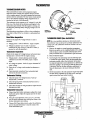
WARNING L1GIITS, ALARMS &CIRCUIT BREAKER
ALTERNATOR WARNINGS
COOLANT TEMPERATURE SWITCH
The Captain Control Panel indicates alternator low discharge
with a red warning light.
The Admiral Control Panel uses a voltmeter to monitor the
performance of the alternator.
A coolant temperature switch is located on the thermostat
housing. This switch will activate a continnous alarm if the
coolant's operatiog temperature reaches approxiroately 21O'F
(99'C).
THERMOSTAT
ASSEIVIBLY,
---
OIL GALLERY
LOW OIL PRESSURE ALARM SWITCH
A low oil pressure alarm switch is located on the engine
block. This switch's sensor monitors the engine's oil pressure. Should the engine's oil pressure fall to 5 - 10 psi
(0.4-0.7 kglcm'), this switch will activate a pulsating
alarm.
ENGINE CIRCUIT BREAKER
The DC harness on the engine is protected by an enginemounted manual reset circuit breaker (20 amps DC).
Excessive current draw or electrical overload anywhere in
the instrument panel wiring or engine wiring will cause the
breaker to trip. In this event most engines' will shnt down
because the opeued breaker disconnects the fuel supply. If
this should occur, cbeck and repair the source of the problern.
After repairing the fault, reset the breaker and restart the
engine.
Engll1~s
& Generators
10' -
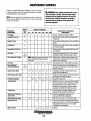
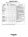
MAINTENANCE SCHEDULE
In order to use this Maintenance Schedule, it will be necessary
A WARNING: Never attempt to perform any service
to log your engine hours. Use yor engine hounneter or record
your engine hours by running time.
while the engine is running. Wear the proper safety
equipment such as goggles and gloves, and use the
cofrect tools for each job. Disconnect the battery
terminals when servicing any Df the engine's DC
electrical equipment.
NOTE: Many of the following maintenance jobs are simple but
others are more difficUlt and may require the expert knowledge
a! a service mechanic.
SCHEDULED
MAINTENANCE
Fuel Supply
CHECK
EACH
DAY
HOURS OF OPERATION
50
100
250
500
EXPLANATION OF SCHEDULED
MAINTENANCE
750 1000 1250
Diesel No.2 rating of 45 cetane or higher.
Fuel/Water Separator
0
0
Engine Oil Level
0
Oil level should indicate between MAX. and LOW on
dipstick.
Coolant Level
0
Check at recovery tank; if empty, check at manifold.
Add coolant if needed.
Transmission Fluid Level
0
Fluid level should indicate between MAX and LOW
on the dipstick
0
Inspect for proper tension (3/8" to 1/2" deflection)
and adjust if needed. Check belt edges for wear.
Drive Belts
Check for water and dirt in fuel (drain/replace filter
if necessary).
weekly
Visual Inspection of Engine
0
NOTE: Please keep engine surface clean. Dirt
and oil will inhibit the engine's ability to
remain cool.
Fuel Filter
Starting Batteries
(and House Batteries)
0
0
0
0
0
0
Check for fuel, oil and water leaks. Inspect wiring
and electrical connections. Keep bolts & nuts tight.
Check for loose belt tension.
Initial change at 50 hrs, then change every 250 hrs.
Check electrolyte levels every 50 operating hours
and make sure connections are very tight. Clean off
excessive corrosion.
0
weekly
Engine Oil (and filter)
0
0
0
0
0
0
0
Initial engine oil & filter change at 50 hrs., then
change both every 250 hours.
Heat EXChanger Zinc Anode
0
0
0
0
0
0
0
Inspect zinc anode, replace if needed, clear the heat
exchanger end of zinc anode debris.
0
0
0
0
0
0
0
0
0
Change every 200 hours.
0
0
0
0
Fuel/Water Separator
Exhaust System
0
Engine Hoses
0
Throttle and Transmission
Conlrol Cable
0
Adjusl Engine Idle Speed
0
Initial check at 50 hrs., then every 250 hrs. Inspect
for leaks. Check anti·siphon valve operation. Check
the exhaust elbow for carbon and/or corrosion
buildup on inside passages; clean and replace as
necessary. Check that all connections are tight.
0
Hose should be hard & tight. Replace if soft or
spongy. Check and tighten all hose clamps.
0
0
0
Check for loose fittings, cotter pins, etc
Lubricate wilh WD-40 or equivalent.
"800-1000 rpm (adjust for transmission used)
Raw Water Pump
0
0
0
Remove Ihe pump cover and inspect Ihe impeller,
gasket, cam and cover for wear. Check the bearings
and seals (the shaft can turn, but not wobble).
Lubricate when reassembling.
Inlel Fuel Filler
0
0
Replace.
0
0
0
""'" WESTERBEKE
Engines & Generators
11
MAINTENANCE SCHEDULE
NOTE: Use the engine hourmeter gauge to log your engine hours or record your
engine hours by running time.
SCHEDULED
MAINTENANCE
CHECK
EACH
OAY
HOURS OF OPERATION
50
MAINTENANCE DESCRIPTION
100 250 500 750 1000 1250
D
Coolanl Syslem
D
DC Alternalor
D
D
Drain, flush, and refill cooling system with
appropriate antifreeze mix.
D
Check DC charge from alternator. Check mounting
bracket; tighten electrical connections.
Transmission Oil Cooler
D
Remove; have professionally cleaned and pressure
tested.
Engine Transmission
Damper Plate
D
Chattering at idle and low rpms is an indication
of damper plate wear. Remove and replace.
D
*Fuelln/eclors
Check and adjust injection opening pressure 'and
spray condition.(see ENGINE ADJUSTMENTS)
*Slarter Molor
D
D
Check solenoid and motor for corrosion. RemoVe
and lubricate. Clean and lubricate the starter motor
pinion drive.
*Preheat Circuli
D
D
Check operation of preheat solenoid. Remove and
clean glow plugs, check resistance value of heater
element (0.9 Ohm). Reinstall with anti-seize
compound .on the threads.
*Engine Cylinder
ComRression
D
D
Check compression pressure and timing (see Engine
Adjustments).
*Adjusl1he Valve Clearances
D
D
*Heal Exchanger
D
Lubricale Panel Key Swilch
with "Lockeze"
Transmission Fluid
D
D
Adjust Valve Clearances (see ENGINE
ADJUSTMENTS).
D
Remove, have professionally cleaned and pressure
tested.
D
D
D
D
D
At first 100 hours, Ihen each year at winterizing.
D
D
D
D
D
Initial fluid change at 25 hours, then every
300 hours or at winterizing.
*WESTERBEKE recommends this service be performed by an authorized mechanic.
/
"'SoY"
WESTERBEKE
Engines'& (ilenerators
12
COOLING SYSTEM
DESCRIPTION
Westerbeke marine diesel engines are designed and equipped
for fresh water cooling. Heat produced in the engine by combustion and friction is transferred to fresh water coolant
which circulates throughout the engine. This circulating fresh
water coolant cools the engine block; its internal moving
parts, and the engine oil. The heat is transferred externally
from the fresh water coolant to raw water by means of a heat
exchanger. similar in function to an automotive radiator. Raw
water flows through the tubes of the heat exchanger while
fresh water coolant flows around the tubes; engine heat transferred to the fresh water coolant is conducted through the
tube walls to the raw water which is then pumped into the
exhaust system where finally it is discharged overboard. In
other words, the engine is cooled by fresh water coolant, this
coolant is cooled by raw water, and the raw water carries the
transferred heat overboard through the exhaust system. The
FI~TER
INSPECTANO
. CLEAN EVERY
laa HOURS
TYPICAL RAW WATER INTAKE STRAINER
(Owner Installed)
INCOMING
RAW WATER
fresh water coolant and raw water circuits are independent of
each other. Using only fresh water coolant within the engine
allows the cooling water passages to stay clean and free from
harmful deposits.
/
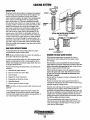
RAW WATER INTAKE STRAINER
SEACOCK-~""
A major part of the raw water cooling system is a proper
boatyardlbuilder installed intake strainer.
-....;::-,::.==-;;;>< .
DRAINING THE RAW WATER SYSTEM
NOTE: Always install the strainer at or below the waterline so
the strainer will always be self-priming.
A clean raw water intake strainer is a vital component of the
engine's cooling system. Include a visual inspection of this
strainer when making your periodic engine check. The water
in the glass should be clear.
Perform the following maintenance after every 100 hours of
operation:
1. Close the raw water seacock.
2. Remove and clean the strainer filter.
3. Clean the glass.
4. Replace the washer if necessary.
5. Reassemble and install the strainer.
6. Open the seacock.
7. Run the engine and check for leaks.
~
When freezing temperatures are expected, it is best to
protect the raw water cooling circuit and engine e)(haust
from damage.
This procedure is best accomplished by disconnecting the
water intake hose from the vessels Ibm-hull fitting. Close the
intake valve before disconnecting the hose. Insert the hose
end into a large container of fresh water.
Before starting the engine, remove the engine thermostat
(replace the gasket and cover). This will ensure a full flow
of water Ibm the engine. Re-install the thermostat once
Hnshing is complete.
Run the unit for \0 minutes or longer to adequately flush the
cooling
..system.
---.
-. Provide an external fresh water supply for the bucket to
maintain the water level in the bucket while the unit is being
operated during the fiushing process.
-
NOTE: Also follow the above procedure after having run hard
aground.
.
The fresh water will fiush out the engines water passages and
. exhaust lines. If the engine is being stored and there is a
probability of freezing, flush the engine with fresh water and
then prior to shutting the unit down substitute the fresh water
supply with a concentrated antifreeze mixture and run this
through the engine to provide freeze and corrosion protection
for both the engine and exhaust system.
When recommissioning, make certain the valves and
seacocks are open so the engine will quickly receive fresh.
water. if the engine is stowed where it is warm, the fresh
water can stay in the engine.
If the engine temperature gauge ever shows a higher than
normal reading, the cause may be that silt, leaves or grass
may have been caught up in the strainer, slowing the flow of
raw water through the cooling system.
Engines & Generators
13
COOLING SYSTEM
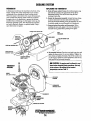
THERMOSTAT
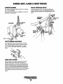
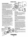
REPLACING THE THERMOSTAT
A thermostat, located near the manifold at the front of the
engine, controls the coolant temperature as the coolant
continuously flows through the closed cooling circuit.
When the engine is first started, the closed thennostatprevents coolant from flowing (some coolant is by-passed
through a hole in the thermostat to prevent the exhaust
manifold from overheating). As the engine warms up, the
thermostat gradually opens. The thermostat is accessible
and can be checked, cleaned, or replaced easily. Carry a
spare theimostat and gasket.
1. Drain off some coolant: Release the coolant pressure cap
and drain the coolant to the approximate level off the
thermostat housing. This can be done using the heat
exchanger drain plug.
2. Rotate the thermostat assembly: Loosen the hose clamp
as shown and remove the three allen screws that hold
down the thermostat housing cover, the assembly can now
be twisted enough to access the gasket and thermostat.
3. Remove/replace the gasket and thermostat: When
installing the new parts, apply a thin coat of sealant on
both side of the gasket before pressing it into place.
THIS HOSE CLAMP
HEAT
EXCHANGER
COOLANT PRESSUIRE CAP--\\
,
~7''''___ ~
PASSAGE
(KEEP CLEAN)
~-assemble
(
l~
:n;:t: Thm the cover back into place and
tighten the three screws. Do not over-tighten! Tighten the
hose clamp and tighten the dntins. Top off the coolant and
mn the engine. Check for normal temperature and for any
leaks around the thermostat assembly.
A CAUTION: The engine lIJust be allowed to cool
down before attempting these procedures_ Not only
is the surface of the engine hot but coolant
temperatures can be at 190· F.
THERMOSTAT
ASSEMBLY
GASKET
SEAL WITH Hh'A"'i
1I'1r)+---JIIR BLEED
. PETCOCK
THERMOSTAT
HOUSING COVER
COOLANT
SWITCH
I;ng/nes.& GllheratQrs
. 14 .
.
COOLING SYSTEM
FRESH WATER COOLING CIRCUIT
CHANGING COOlANT
NOTE: Refer to the ENGINE COOLANT section for the rec-
The erigine's coolant must be changed according to the
MAINTENANCE SCHEDULE. If the coolant is allowed to
become contaminated, it can lead to overheating problems.
ommended antifreeze and water mixture to be used as the
fresh water coolant.
Fresh water coolant is pumped through the engine by a circu'Iating pump, absorbing heat from the engine. The coolant
then passes thrqugh the thermostat into the manifold, to the
heat exchanger where it is cooled, and returned to the engine
block via the suction side of the circulating pump.
When the engine is started cold, external coolant flow is prevented by the closed thermostat (although some coolant flow
is bypassed around the thermostat to prevent the exhaust
manifold from overheating). As the engine warms up, the
thermostat gradually opens, allowing full flow of the engine's
coolant to flow unrestricted to the external portion of the
coolinll s¥stem.
critlcalj a substantial number of engine failures can be
traced back to cooling system corrosion.
Drain the engine coolant by loosening the drain plug on the
engine block and opening the manifold pressure cap. Flush
the system with fresh water, then start the refill process.
NOTE: The drain on the heat exchanger should also be used
to help drain engine coolant.
~
KEEP THE
COOLANT PASSAGE
CLEAR
TO COOLANT
RECOVERY TANK
A CAUTION: Proper cooling system maintenance is
ENGINE BLOCK
fl00LANT DRAIN
~"~
OIL GALLERY
FROM COOLANT
RECOVERY TANK
Refilling the Coolant
After closing the engine block drain, pour clean, premixed
coolant into the manifold and when the coolant is visible in
the manifold, start the engine and run it at slow idle. Open
the air bleed petcocks on the manifold and the thermostat
housing.
Monitor the coolant in the manifold and add as needed. Fill
the manifold to the filler neck and when the coolant flowing
from the petcock is free of air bubbles, close the petcock and
install the pressure cap.
Remove the cap on the coolant recovery tank and fill with
coolant mix to halfway between LOW and MAX and replace
the cap. Run the engine and observe the coolant expansion
flow into the recovery tank. When the petcock on the thermostat housing is free of air bubbles, close that petcock.
J\fter checking for leaks, stop the engine and allow it to cool.
Coolant should draw back into the cooling system as the
engine cools down. Add coolant to the recovery tank if
needed. Clean up any spilled coolant.
COOLANT RETRACTION
NOTE: Periodically check the condition of the manifold
pressure cap. Ensure the upper and lower rubber seals are ill
good conditiOl~ Check to ensure
.
the vacuum. valve opens and
closes tightly. Cany a spare
cap. Check also to ensure the
cooLant passa.ge is clear so
coola:nt within the system is
able to expand and contract
to andfrom the coolant recovel)'tank
SEAL
Coolant Recovery Tank
A coolant recovery tank allows for engine coolant expansion
and contraction during engine operation, without any significant loss of coolant and without introducing air into the cooling system. This tank should be located at or above the
engine manifold level and should be easily accessible.
A WARNING: Beware of the hot engine coolant.
NOTE: TI.;s tank, with its shOlt run ofplastic hose, is best
Wear protective gloves.
located at or above the level of the engine ~ manifold.
'~/WESTERBEKE
"" _,__ ::1..Enaines & Generators
15
COOLING SYSTEM
RAW WATER COOLING CIRCUIT
The raw water flow is created by a positive displacement
impeller pump. This pump draws water directly from the
ocean, lake, or river through a hose to the water strainer. The
raw water passes from the strainer through the heat
exchanger (through the heat exchanger tubes) where it cools
the engine'circulating fresh water coolant. The raw water is
then discharged into the water injected exhaust elbow, mixing with and cooling the exhaust gasses. This mixture of
exhaust gas and raw water is pushed overboard.
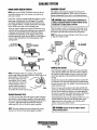
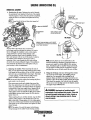
Raw Water Pump
BAD
NEW:'
The raw water pump is a self-priming, rotary pump with a
non-ferrous housing and a neoprene impeller. The impeller
has flexible vanes which wipe against a curved cam plate
within the impeller housing, producing the pumping action.
On no account should this pump be run dryas water acts as a
lubricant for the impeller. There should always be a spare
impeller and impeller cover gasket aboard (an impeller kit).
Raw water pump impeller failures occur when lubricani (raw
water) is not present during engine operation. Such failures
are not warrantable, and operators are cautioned to make sure
raw water flo~ is present at st~-up.
Heat Exchanger
BA~
ZINC ANODES
The heat exchanger is a copper tube which encloses a number of small copper tubes. Raw water is pumped through the
small copper tubes and the freshwater coolant from the
engine is circulated around the copper tubes. The raw water
removes heat from the freshwater coolant.
Zinc Anode
NOTE: Should afailure occur with the pumps internal parts
A zinc anode, or pencil, is located in the raw water cooling
circuit within the heat exchanger. The purpose of the zinc
anode is to sacrifice itself to electrolysis action taking place
in the raw water cooling circuit, thereby reducing the effects
of electrolysis on other components of ttie system. The condition of the zinc anode should be checked monthly and the
anode cleaned or replaced as required. Spare anodes should
be carried on board.
(seals and bearings), it may be more cost efficient to
purchase a new pump and rebuild the original pump as
a spare.
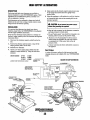
Inspecting/Changing the Raw Water Pump Impeller
Close the raw water intake valve. Remove the pump cover
and, with the proper size impeller tool, carefully pry the
impeller out of the pump (the impeller can be pried out using
a pair of screwdrivers if an impeller puller is unavailable. Take
care not to tear the impeller). Install the new impeller and
gasket. Move the blades to conform to the curved cam plate
and push the impeller into the pumps housing. When
assembling, apply a thin coating of lubricant to the impeller
'.
and gasket. Open the raw water intake valve.,
Run the ~ngine and check for leaks around the pump. Also
check for water discharge at the stem tube. Absence of w.(lter
flow indicates the pump has not primed itself properly.
NOTE: Electrolysis action is the result of each particular
install~tion
and vessel location; not that of the generator. '
If the zinc pencil needs replacement, hold the hex boss into
which the zinc pencil is threaded with a wrench while loosening the anode with another wrench. This prevents the hex
boss from possibly tearing off the exchanger shell. After
removing the zinc, note the condition of it. If the zinc is in
poor condition, there are probably a lot of zinc flakes within
the exchanger. Remove the end of the heat exchanger and
clean the inside of all zinc debris. Always have a spare heat
exchanger end gasket in case the present one becomes damaged when removing the end cover. Replace the gasket (refer
to your engine model's heat exchanger end gasket part number), a-ring, cover, and install a new zinc pencil.
NOTE: Never allow the pump to run dry. Even a short period
of dry running may destroy the impeller.
RAW WATER PUMP
PN52650
Heat, Exchanger Service
INSPECTION: CHECK THE BASE OF
EACH BLADE BY BENDING VIGOROUSLY.
REPLACE THE IMPELLER IF THERE ARE
ANY CRACKS,
After approximately 1000 hours of operation, remove, clean
and pressiIre test the engine's heat exchanger. (A local auto, motive radiator shop should be able to clean and test the heat
, . ':: exchanger.)
NOTE: Operating in silty and/or tropical waters may require
that a heat exchanger cleaning be performed more often than
every 1000 hours.
~ WESTERBEKE
Englnes'& Generators
16
WATER HEATER
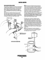
WATER HEATER INSTALLATIONS
NOTE: If any portion of the heating circuit rises abov~ the
These engines are equipped with connections for the plnrnbing
of engine coolant to transfer heat to an on-board water heater.
The water heater should be mounted in a convenient location
either in a high or low position in relation to the engine, so
that the connecting hoses from the heater to the engine can
run in a reasonably direct line without any loops which might
trap air.
Hoses SllOUld rise continuously from their low point at the
heater io the engine so that air will rise naturally from the
heater to the engine. If trapped air is able to rise to the heater,
then an air bleed petcock must lie installed at the higher fitting
on the heater for bleeding air while filling the system.
engine's own pressure cap, then a pressurized (aluminum)
remote expansion tank (Kit #024177) must be installed in the
circuit to become the highest point. Tee the remote expansion
tank into the heater circuit, choosing the higher of the two
connections for the return. Tee at the heater, and plumb a
single line up to the tanks location and the other back to the
engine ~ retz{m. Install the remote expansion tank in a
convenient location so the coolant level can easily be checked.
The remote expansion tank will now serve as a check and
system fill point. The plastic coownt recovery tank is not used
when the remote expansion tank kit is installed, since this
tank serves the same function. Remove and store the plastic
recovery tank if it has been already installed.
THERMOSTAT HOUSING
The pressure cap on the engine's manifold should be
installed after the engine's cooling system is filled with
coolant. Finish filling the cooling system from the remote
tank after the system is filled and is free of air and exhibits
good coolant circulation. During engine operation, checking
the engine's coolant should be done at the remote tank and
not at the engine manifold cap. The hose connection from the
heater to the remote expansion tank should be routed and
supported so it rises continuously from the heai:er to the tank,
enabling any .air in the system to rise up to the tank and out
of the system.
!
NOTE: An air bleed petc~ck is located on the ·engine 's
heat exchanger. Open this petcock when filling the engine's
coolant system to allow air in the exchanger to escape.
Close tightly after all the air is removed.
~.-:--
~
---
.OWNERS HOT WATER HOSE
: FROM HOT WATER TANK
REMOVE EXPANSION·
TANK (024177)
WATER HEATER CONNECTIONS
I'W'IiTIWESTERBEKE
I ...
Enaines
&. GtmeratorS:
"" -17--
I
FUEL SYSTEM
DIESEL FUEL
Use No.2-D (SAE J3l3) diesel fuel with a Cetane rating of
#45 or higher. Grade of diesel fuel according to ASTM D975.
In conjunction with Ultra Low Sulphur Diesel. Use an
additive such as Diesel Kleen + Cetane Boost to help restore
lubricity back into the diesel.
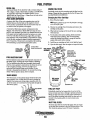
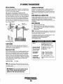
fUEL WATER SEPARATOR
Periodically check the fuel connections and the filter bowl for
leakage. Change the filter element after the first 50 hours. See
the MAINTENANCE SCHEDULE.
Changing the Filter Cartridge
1. Shut off the fuel supply.
A primary fuel filter of the water separating type must be
installed between the fuel tank and the engine to remove
water and other contaminants from the fuel before they can
be carried to the fuel system on the engine.
NOTE: Slide a plastic bag up over the fuel filter cartridge
as it will be full offuel.
A typical fuel filter/water separator is illustrated in this
diagram. This is the Raycor Model 500 MA. Keep in mind
that if a water separator type filter is not installed between the
~uel supply tank and engine-mounted fuel system, any water
l~ the fuel will affect the fuel pump, engine filter, and injeclIon equipment. The owner/operator is responsible for making
certain the fuel reaching the enSine's injection equipment is
free of impurities. This process is accomplished by installing
and maintaining a proper filtration/separation system.
TYPICAL FUEL
FILTER/WATER
SEPARATOR
ENGINE FUEL filTER
2. Unscrew the cartridge from its housing and remove the
cartridge and its gasket.
.
3. Wipe both the housing and the top of the new cartridge
with clean fuel.
4. To help reduce fuel system priming, fill the fuel filter
with diesel before installing. This will dramatically
reduce the pliming time needed to purge air from the
engines fuel system before starting.
5. Install the new cartridge and spin on real tight by hand.
6. Open the fuel supply. Run the engine to inspect for leaks.
10 micron filter
element recommended.
LIGHTLY WIPE
WITH CLEAN FUEL
WHEN INSTALlING
THE NEW FUEl
FILTER CARTRIDGE
FUEL INJECTION PUMP
The fuel injection pump is the most important component of
the diesel engine, requiring the utmost caution in handling.
The fuel injection pump has been thoroughly bench-tested
and the owner-operator is cautioned not to attempt to service
it. If it requires servicing, remove it and take it to an
authorized fuel injection pump service facility. Do not
attempt to disassemble and repair it. Do not send the timing
shims with the injection pump, leave on engine.
LIFT PUMP
BlEEOSCREW
The bleed screw on the injection pump should be left in the
open position. This wili then allow for ease in priming the
engine's fuel system and during engine operation allow for
air in the system to be delivered to the fuel tank through the
fuel return system.
FUEL FILTER
CARTRIDGE
JtJOOCl
FUEL LIFT PUMP
Periodically check the fuel connections to and out of the
pump and make sure that no leakage is present and tllat the
fittings are tight and secure. The DC ground connection at
one ofthe pumps mounting bolts should be clean and well
secured by the mounting bolts to ensure proper pump
operations.
INLET FUEL FilTER
To ensure clean fuel into the fuel lift pump, there is a small
in-line fuel filter connected to the fuel lift pump elbow. This
filter should be replaced every 250 hours of operation.
Engines & Generators
... ··1-8-- -
ENGINE LUBRICATING OIL
I • ••
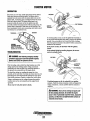
ENGINE OIL CHANGE
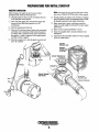
1. Draining the oil sump. Discharge the used oil through
the sump drain hose (attached to the front of the engine)
while the engine is warm. Drain the used oil completely,
replace the hose in its bracket and replace the end cap
securely.
NOTE: Thread size for the lube oil drain hose capped elld
is JI4NFT.
APPLY CLEAN
ENGINE OIL
INSTALLING
'+-Smm [11/161 SOCKET
FOR EXTENSION
114" NPT
REMOVE USING AN 8MM (17176'/ SOCKET
. TO DRAIN THE OIL OR PUMP THE WARMED
OIL UP THRU THE HOSE.
Always ooserve the used oil as it is removed. A
yellow/gray emulsion indicates the presence of water in
the oil. Although this condition is rare, it does require
prompt attention to prevent seriousdarnage. Call a
qualified mechanic should water be present in the oil.
Raw water present in the oil can be the result of a fault in
the exhaust system attached to the engine and/or a
siphoning of raw water through the raw water cooling
circuit into the exhaus~ filling the engine. This problem is
often caused by the absence of an anti-siphon valve, its
poor location or lack of maintenance.
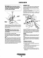
OIL FILL r___ /
2. Replacing the ailfilter. When removing the used oil
filter, you may· find it helpful and cleaner to punch a hole
in the upper and lower portion of the old filter to drain the
oil from it into a container before removing it. This helps
to lessen spillage. A small automotive filter wrench
should be helpful in removing the old oil filter.
NOTE: Do not punch this hole without first loosening the filter to
make certain it can be removed.
Place some paper towels and a plastic bag around the
filter when unscrewing it to catch any oil left in the filter.
(Oil or any other fluid on the engine reduces the engine's
cooling ability. Keep your engine clean.) Inspect the old
oil filter as it is removed to make sure that the rubber
sealing gasket comes off with the old filter. If this rubber
sealing gasket remains sealed against the filter bracket,
gently remove it.
When installing the new oil filter elemen~ wipe the filter
gasket's sealing surface on the bracket free of oil and
apply a thin coat of clean engine oil to the rubber gasket
on the new oil filter. Screw the filter onto the threaded oil
filter nipple on the oil filter bracket, and tighten the filter
firmly by hand.
NOTE: The engine oil is cooled by enginecoolantfiowing
through passages in the oil filter brack.et housing assembly
l!3
NOTE: Generic filters are not recommended, as the
material standords or diameters of important items on
generic parts might be entirely different from genuine
parts. Immediately after an oil filter change and oil fill,
run the engine to make sure the oil pressure is normal
and that there are no oil leaks around the new oil filter.
3. Filling the Oil Sump. Add new oil through the oil filler
cap on the top of the engine. After refilling, run the
engine for a few moments while checking the oil
pressure. Make sure there is no leakage around the new
oil filter or from the oil drain system, and stop the engine.
Then check the quantity of oil with the lube oil dipstick.
Fill to, but not over the high mark on the dipstick, should
the engine require additional oil.
A WARNING: USed engine oil contains harmful
contaminants. Avoid prolonged skin contact. Clean skin
and nails thoroughly using soap and water. Launder or
discard clothing or rags containing used oil. Discard
used oil properly.
Engines. &. Generators
19
REMOTE OIL FILTER (OPTIONAL) .
To install, simply remove the engine oil filter and thread on
WESTERBEKE's remote oil filter kit as shown. Always
install this kit with the oil filter facing down as illustrated.
Contact your WESTERBEKE dealer for more information
NOTE: Westerbeke is not responsible for engine failure due to
incorrect installation of the Remote Oil Filter.
INSTALLATION
This popular accessory is used to relocate the engine's oil
filter from the engine to a more convenient location such as
an engine room bulkhead.
NOTE: Refer to ENGINE OIL CHANGE in this manual for
instnlctions on removing the oilfilter.
A'
CAUTION: It is vital to install the ai/lines correctly. If the oil flows in the reverse direction, the bypass valve in the filter assembly will prevent the oil
from reaching the engine causing an internal engine
failure. If there is no ai/ pressure reading, shutdown
immediately and check the hose connections.
FASTEN SECURELY TO A BULKHEAD
(SCREWS ARE OWNER SUPPLIED)
APPLY A THIN COAT OF CLEAN OIL TO THE O·RING WHEN
INSTALLING THIS KIT. THREAD THE KIT ON, THEN HAND
TIGHTEN AN ADDITIONAL 3/4 TURN AFTER THE O·RING
CONTACTS THE BASE.
i
THE IN CONNECTION HOSE
MUST ATTACH TO THE OUT
CONNECTION ATTHE •
/H'MU"OIL FILTER.
NOTE THE "IN"
"OUT" MARKINGS
ON THE ADAPTER WHEN THE HOSES ARE
REMOVED FOR INSTALLATION SO THEY
WILL BE RECONNECTED CORRECTLY
THE
HOSE
MUST ATTACH TO THE IN
CONNECTION ATTHE
REMOTE OIL FILTER.
Engines & Generiitors
20
APPLY A THIN COAT OF
OIL TO THE FILTER
GASKET WHEN INSTALLING. AFTER THE FILTER
CONTACTS THE BASE, TIGHTEN IT AN ADDITIONAL
3/4 TURN.
WIRING DIAGRAM
#39144
~I
19
".
R~8RED
114 L 1. BtU
\'
tl4 IT. BLU
'''RE.
Oil PRESSURE
"'~~&HM-~'
1------
lliID·
.
'14 OR
15[[ NOTE Z
,,j~,,
, , -'
,,
GROUND
"
BLOCK
~
+lufl
illL.fQM<
~-==lliI..E..B.1
0
. ,
". .
,
>
"
" ~.: " «
OME MODElS)
liN IS FOR 6SA
Af NOT HAVE
RUN SOLENOID
"
IS CONNECHD
RMIN4L ON SOLEN!)IO
; :
"~
,
,
~.;
;H~ ~~~~
.:;;; ~;;;
:!
~
®
•
;
+
ALARM
C
BUZZER
ADMIRAL
PANEL
,r,
--~
WATER TEMP.
- -aLMa&"
~
--------
-
--
~
,
, ' @
,,
,
'"'
'"' '"~ ,. ~
,
,
~ o ~ """V
,,,
~:;
~F ',--:7
,,
~
,,
.14 BRN
,
,,
~IO~ED~ ,
sw. I
,,,
,
--------------------------------~
.14
R~D
11!4 BlK@
.14 B K 0
>
"
114 REO
KEYSWITCH
VOL.TMETER
.10 UP
" (~\:\~ ~
JII ~ll 'I
5TAAT 5W.
"
PfII!HEAT
,,
~
CAPTAIN
PANEL
~
;
~
IH II
r-
,,r
,
,,
,
,,,
,,
,
,,
,,
"
,
,,
-
-- -
'+;~I
~
""'''' ~
cr-
"'; c;5 "" ~
0
t
LA""
T ')
r'
OP.~ L
,
-
-- .-
1
t:;\
,,~
~H
-
J
1--
,
,,",,'(:::'r' '1
.-=-..
J
f--)m~
.~~'
I
I '"""
- ----
21
II
~
Q)®
-,
WIRING SCHEMATIC
.;:
vac
I<
START
SOL _
#39144
OJ
STARTER
r-----+i--<, -:,
_ .. _ .. _ .. _ .. +-.
M)---c----+
-1
f"7o ~~l~
PREHEAT
-
. _.' -
-'1
..
!'R~TER~'I=
r--,SDL
~-:
.
1 ,I ~J~;~ mOE"
GLOWPlUGS
~.
AL HRNHOH
__
"OLO
•
l'2C '20B
.
( '"
LI FT
TIMER
"l~~ ]SC~
-
1
..
~"""
.•
[O~~ I
44A ONLY HClO
IwRtN 05£61
lITlTlS:
CO.
..
FUEL SOL
.. _ .. - - .
.
,. THI S PRODUCT IS PRIiT£CHO BY A ~UUAL RESET C I Reu I T BREAKER LOCATED NEAR THE
START£R.
EXCESSIVE CURRENT WILL C~USE THE BREAKER TO TRIP AND THE ENGINE WILL
SHUT DOWN.
THE BUILnERIOyjNER MUH BE SURE THAT THE INSTHUMEHl fANEL. WIRING. AND
ENGINr ARE INSTALLED TO PREVENT CONHer BEl'l(EEN ELECTRICAL OEVICES AND SEAWATER.
PU~P
All ON-orr SWITCH SHOULD tiE INSTALLEO BHWErN TN[ B~TTi:Rr AND STARTER TO
DISCONNECT THE BATTtRY IN AN EMERGENCY AND WHEN LHYING THE BOAT.
A SWITCH
WIU A CONTINUOUS RATING OF !75 *MPS.
AT Il VOC Will SERVE THIS rUHCTION. THIS
SWITCH SHOULD NOT BE USED TO MAKE OR BREAK TH£ CIRCUIl.
2
l. THE PINK WIRE AT PLUG 2 IS UNUSED AND SHOULO BE INSUE-U[O. CAPTAIN PANEl ONLY.
4. THE GRAY WIRE AT ?LUG Z IS UNUSED ANO SHOULD BE INSULATED.
~14l1
U
~O""RAL
PANEL OHlY.
114PNK
®
BIILMAR
100 AMP.
liLT.
114 BlK
ADM I RAL
PANEL
. a'' ,".
'"
""
90 liMP.
114 PINK
A'
-
~OlT
/"'"
UN~"R
.14 LT BLU
~"""""'~I).
START
"
1iJ~1m
BHTtRl •
~
•
.'.
16 RED
o
S GAUGE
I
GNO
PREH[AT
SWTTCH
liLT.
VO T S NSOR
J3,
1I4BLU
Ji
-
.~
/
~ ®
li.u"'1~""O"
0
"!..!!J!LJ'"
~v-----~
•
OIOONO
118 RED
TAP
~A.~-+-'''"·-'"""'-"
• '4 BRN
AC UP
MI4 BRN
[
.
~Q
MIHii6lSHI
AMP AlT.
0
,
PH
"'1
1110 ORN
\'
~'"
"
'"/ffi
LAMP
I
START
". j
II I 4 GRA
04 02
"
~ ~A~P "
I
TT
PREHEAT
SWITCH
(£)
CAPTAIN
PANEL _
0]
"CP
..FJ
HOTE:
WIRE fOR BATTERY AlTATCH!.IENT WilL NEED
TO BE UPGRADED TO .AN 6 GAUGE rAOM 10 GAUGE
®
0
"-
.• ~rA~p
114 BRN
l
1114 PUR
"' "
'"
I
P
0
1114 BRN
PRESTOll I f 72 AMP
o
0
'"
AI T
UNIVERSAL PROPUlSION
PRESTOl I iE 5 I AMP. AI T
GRA~0
~~IORED
~
1114 LT. BlU
<
,
, ,
1114 P1NK
~'r::rr,~
ALARM
ElCltH]/
8l
y
L1. SLU
114 PINK
1114 PINK
51
AMP.
AI TERNATOR
~
STANDARD ALTERNATOR ON THE
o
I 0 REO
1114 eRN
1114
55C. 638. 63C. 64A. 718.
82B. 108B.
~
108C.
LT.
114 BRH
LESTEK
100 AMP. AlT
®
I
14 BRN)"
WHT
no
!TACHICD
MAlE'tO~NECTO~\
~14 LT. 8LU
'"'
""
.14 PINK
~
pN THIS SIDE
~I
--......,.'~lT~CHJ~
..~.~"", ~>-"-~~~=mi:~~~~'=
~=lt,A __~l
:'
.
fr'" '[I'"":\';'1(lU~'"""
,,<,,",;;",;;,";;;.".~.~;';~!.,:~~~~,c",CCt.119Id~
a~TT£~
L'.!J
U~ING
1
a~Tl[RIES) ~.,
•• ,a·1
:
l;~
~
o
I
-~----'
o
~
::1
I.
~W~~~5c~w~u~m(~~~s.
'~Ol
OPTIONAL ALTERNATORS@ocUloNI
135A. IGOA. 190A. LESTEHIBALMAR ALTrRNA10RS
AVAli MIj £ ON THE MSOB 5~C 63B 6lf
&4A 11B a2B
108B
~
~
14 RED
LU
-----;i,:~,*;_1~&UhDI ~I ~ 14 ~
If
(NOT USED) 1
4 RED
U4
~14
~.
MAl[ COHNECTO~\
ON THIS SIDE
I
IOBC OULL
22
RfGU! ATOR .
IIIOUNT IN A COOL
LOCATIONi
I:
ENGINE ADJUSTMENTS
REMOVING THE INJECTORS
Inspecting Spray,Pattern
NOTE: Injector must be selViced in a "clean room" enviromnent
C Disconnect the high pressure lines from Ille injectors and
1. Operate the hand lever of the nozzle tesler at intervals of.
on.e stroke per second to check if tlle fuel is injected Correctly in its axial directiori. A nozzle is defective ifit
injects fuel in an oblique direction or in several separate
strips. Also, a spray in tile form of particles indicates a
defect. These defects may sometimes be caused by clogging with dust and, therefore, all parts should be carefully
cleaned before reassembly. (Care should·be taken not to
expose ones skin to this spray as it may penetrate tile skin
and cause infection.)
loosen the lines at their attachment to the injection pump
and move them out of the way of the injectors. Avoid
bending the lines.
2. Using a 17mm long socket, remove the fuel return line in
its entirety from the top of the injectors. Thke care not to
lose the two sealing washers and banjo bolt that attaches
lbe fuel return line to each injector.
. ~.
NOTE: Clean the area around the base of the injector
prior to lifting it out of the cylinder head to help prevent
any rust or deb/is from falling down into the inj~ctor
hole. If the injecto.r will not lift out easily and is held in
by carbon build up or the like, work the injector side to
side with the aid of the 17mm deep socket wrellch to free
it and then lift it out.
3.
I@
1J . . .~
I~
p}
FAULTY
~!l'\'
""'.
1'1'1.
The injector seats in the cylinder head on a copper sealing washer. This washer should be removed with the
injector and replaced with a new washer when the injector is reinstalled.
CHATTERING TEST
II,
-~I, ;FAULTY
h
~I
'II
';0,
2. Apply the pressure of 1991 kg/em' (140 Ib/in') to iJ(izzle
by operating the' hand lever, and check the drips from the
nozzle tip. If it drips or has a large accumulation of fuel
on the bottom, it is considered defective and should be
replaced. A very small amount of fuel may sometimes
remaIn on the tip of the nozzle; however, this does not
indicate a defect.
INJECTION TESTING
1. Using the nozzle tester, check the spray pattern and injec-
tion ~tarting pre~sure of nozzle and, if it exceeds the
limit, adjust or replace the nozzle. When usIng nozzle
tester, take. tile following precautions:
a. ,If the diesel fuel of the nozzle tester is discolored,
replace it. At the same fune, clean or replace the filter.
b. Set the nozzle tester in a clean place where there is no
dust or dirt.
e. Mount the nozzle and nozzle holder on the nozzle
tester.
d. Use·the fueIat the approximate temperature
of 68' F (20· C)
e. Operate the Iland lever of nozzle tester several funes to
bleed the air in.the hOzzle lIne, then move Ille hand
lever at intervals of one strokC per second while reading the injection starting pressure. ,
DRIP TEST
The injection starting pressure for the injectors is adjusted by
increasing or decreasing the thickness of the adjusting shim.
Pressure variation with O.01mm (O.004In) difference of
adjustIng ",asher thickness. 235 kPa (2.4 kgflcm', 4 psi) .
ADJUSTING
A CAUTION: The spray injected from the nozzle is
sf such velocity that it may penetrate deeply into
the skin of fingers and hands, destt-oying tissue. If
it enters the bloodstream, it may cause blood
pOisoning.
FUE{ INJECTION PRESSURE
/.INOZZLE
!SHIM THICKNESS
~
i
.
INJECTION.
TYPICAL INJECTOR
FACTORY SPECIFICATIONS
·13.73 -14.71MPA
,140 -150 kgf/cm'
1991 - 2134 psi
VALVE TIGHTNESS
1. Set the injector nozzle'to a nozzle tester.
2. Raise the fuel pressure and keep it at 12.75 MPa
(130kgf/cm', 1849 psi) for 10 seconds.
3. If a fuel leak is found, replace .the nozzle piece.
. "·FACTORY SPECIFICATIONS
'""'" WESTERBEKE
. _ .E'lglnes Qt__QEmerator~
23
ND fuel leak at:
12:75MPA .
130 kgf/cm"
.1849 psi
ENGINE ADJUSTMENTS
GLOW PLUGS
GLOW PLUG .TIGHTENING TORQUE
2.0 -2.5 m-kg (14.5 -18.0 ff·lb)'
A
WARNING: These glow plugs will become very hot
.to the touch. Be careful not to burn your fingers when
testing plugs.
CONNECTION
To inspect the plug, remove the electtical tenninal connections,
then unscrew or unclamp each plug from the cylinder head.
Thoroughly clean each plug's tip and threads with a soft brush
and cleaning solution to remove all the carbon and oil deposits.
While cleaning, examine the tip for wear and bum erosion; if it
has eroded too much, replace the plug.
An accurate way to test glow plugs is with an ohmmeter.
Touch one prod to the glow plug's wire connection, and the
other to the body of the glow plug, as shown. A good glow plug
will have a 0.9 ohm resistance. This method can be used with
the plug in or out of the engine. You can also use an annneter to
test the power drain (13 amps per plug).
Re-install the plugs in the engine and test them again. The
plugs should get very hot (at the tenninal end) within 5 to 10
seconds. If the.plugs don't heat up quickly, check for a short
circuit. When reinstalling the glow plugs, use anti-seize
compound on the threads.
,..-....lL----""'---- TESTING WITH .
AN OHMMETER
ON • .:TlP
USING A
TEST LIGHT
A CAUTION: Do not ke~pgi~ plug on for more than
30 seconds.
+
GLOW PLUGS
REFER TO THE WIRING
DIAGRAM IN THIS
MANUAL FOR ALL
WIRING CONNECTIONS
-...v- WESTERBEKE
Engines & Generators
24
ENGINE ADJUSTMENTS
NOTE: WESTERBEKE recommends that the following engine adjust·
ments be peifonned by a competent engine mechanic. The infonnation
below is provided to assist the mechanic.
CHECKING VALVE CLEARANCE
Valve clearance must be checked and adjusted when engine
is cold
1. Remove the head cover.
2. Align the ITC mark line on the flywheel and projection
on the housing so that the No.1 piston comes to the
compression or overlap top dead center.
PROJECTION
,
"*
"*
. FLYWHEEL
jHOUSING
ADJUSTING
SCREWS,
4CYL.
No.1
When No.1 pistop is
No.2
compression top dead
No.3
center
,
No.4
/
TIMING WINDOW
Valve, arrangement I-
IN.
\1
ITG MARK
The TC marking line on the flywheel is just for the No.1
There is no TC marking for the other cylinders. The No.1
piston comes to the top dead center position when the TC
marking is aligned with the projection in the window on
the flywheel-housing. Tum the flywheel 0.26 radius (15')
clockwise and counterclockwise to see if the piston is at
the compression top dead center or the overlap position.
Now, referring to the table below, readjust the valve
clearance. The piston is at the top dead center when both
the IN. and EX. valves do not move. It is at the overlap
position when both the valves move.
Finally, tum the flywheel 6.28 radius (360') and align the
TC marking and the projection perfectly. Adjust all the other
valve clearances as required.
After turning the flywheel counterclockwise twice or three
times, recheck the valve clearance.
After adjusting the valve clearance, finnly tighten the locknut
of the adjusting screw.
\
\
FLYWHEEL
1
3. Check the following valve clearance (1) marked with
-!:< using a feeler gauge.
4. If the clearance is not within the factory specification,
adjust with the adjusting screw.
VALVE CLEARANCE 0.23· 0.27mm (0.0091 ·0.0106in)
Adjustable
cylinder
location 01 piston
o
EX;
LOCKNUT
"*
*
No.1
When No.1 piston is
overlap position
No.2
No.3
No.4
"*"*
"*
r-:"'''''''''''~IIiI~ VALVE CLEARANCE
"*
U' 0.23· 0.27mm (0.0091 ·0.010610)
'0
~'a,
Engines & Generators
25
ENGINE ADJUSTMENTS
NOTE: WESTERBEKE recommends that the following engine adjustments be pe/formed by a competent engine mechanic. The information
below is provided to assist the mechanic.
COMPRESSION TESTER
TESTING OIL PRESSURE
To test the oil pressure, remove the oil pressure sender, then
install a mechanical oil pressure gauge in it's place. After
warming up the engine, set the engine speed at idle and read .
the oil pressure gauge.
.
.f- .'
ADAPTER", .
TESTING ENGINE·
COMPRESSION
OIL PRESSURE WILL RANGE BETWEEN 50 AND 55PSI AT 1800 RPM
'..
LOW OIL PRESSURE
"" .
i""",,'".
""'~~INJECTOR DR
~
.
GLOW PLUG HOLE
. COMPRESSION PRESSURE AT 250 RPM
626 psi - 44 Kgf!crtf - 4.32 Mpa
ALLOWABLE LIMIT AT 250 RPM
472 psi - 33.2 Kgf!crtf - 3.26 Mpa
, The specific safe minimum oil pressure is 5 - 10 psi. A gradualloss of oil pressure usually indicates worn bearings. For
additional information on low oil pressure readings, see the
ENGINE
chart.
NOTE: In case of severe vibrations and detonation noise, the
cause may be fuel injector problems, see FUEL
INJECTORS. Poor fuel quality, contaminates and loss of
positive fuel pressure to the injection pump will result· in
injector faults.
OIL GALLERY
When re-installing the glow plugs use anti-seize compound,
MECHANICAL
OIL PRESSURE GAUGE
DRIVE BELT ADJUSTMENT
Excessive drive belt tension can cause rapid wear of the belt
and reduce the service life of the fresh water pump's bearing.
A slack belt or the presence of oil on the belt can cause belt
slipping, resulting in high operating temperatures.
The drive belt is ·properly adjusted if the belt can be
deflected no less than 3/8 inch (IOmm) and no more than 112
inch (12mm) as the belt is depressed with the thumb at the
mfdpoint between the two pulleys on the longest span of the .
belt. A spare belt or belts should always be carried on board.
DlL GALLEIiY
A WARNING: Never attempt to check or adjust the
drive belt's tenSion while the engine is in operation.
ENGINE COMPRESSION
Check tile compression pressure. To do this warm the engine,
remove all fuel injectors, or glow plugs, disconnect the fuel
shut-off solenoid wire, and install a compression adapter in
the injector hole or glow plug hole. Connect a compression
tester on the adapter 'and crank the engine with tl10 starter
motor until the pressure reaches a maximum value. Repeat
this process for each cylinder. Look for cylinders with
dramaticaliy (at least 20%) lower compression than the
average of the others. Compression pressure should not differ
by more than 35.5 psi (2.5 kg/cm'). at 280 rpm.
If a weak cylinder is flaaked by healthy cylinder, the problem
is either valve or piston related. Check the valve clearances
for the weak cylinder, adjust as needed and test again. If the
cylinder is still low, apply a small amount of oil into the
cylinder to seal the rings and repeat the test. If compression
comes up - the rings are faulty.
Abnonnally high readings :on all cylinders indicates heavy
carbon accumulations, Ii condition that might be
accompanied by high pressures and noise.
Adjusting Belt Tension
1. Loosen the alternator pivot bolt.
2. Loosen the alternator adjusting bolt.
3. With the altemator loose, swing it outward until the drive
belt is tensioned correctly.
4. Tighten both bolts.
5. Check the tension again after the engine has been in
operation.
Englne_s &.Generators
26
ADJUSTING
BOLT
TACHOMETER
TACHOMETER/HOUR METER
The tachometerlhour meter used in propulsion engine
instrument panels contains two separate electrical circuits
with a common ground. One circuit operates the hour meter
and the other the tachometer. The hour meter circuit operates
on 12 volts alternator charging voltage supplied to the (+)
tenninal on the back of the instrument.
The tachometer circuit operates on AC voltage 6-8 volts, fed
from one of the diodes in the alternator and supplied to the
tachometer input tenninal while the engine is running, and
the alternator producing battery charging voltage 13.0-14.8
volts DC.
The following are procedures to follow when troubleshooting a fault in either of the two circuits in a tachometerlhour
TERMINAL
COARSE
ADJUSTMENT
meter.
Hour Meter Inoperative
TACHOMETER CHECK (New Installation)
Check for the proper DC voltage between (+) and (-)
tenninals.
1. Voltage present - meter is defective - repair or replace.
2. Voltage not present - trace (+) and (-) electrical
connections forfault. (Jump 12 volts DC to meter (+)
tenninal to verify the operation.)
NDTE: In a new installation having new instrument panels,
the tachometer may not always be correcJly calibrated to the
engine's rpm. This calibration should be checked in all new
installations.
1. Warm up the engine to normal operating temperature.
Remove any specks on the crankshaft pulley with a clean
cloth and place a piece of suitable reflecting tape on the
pulley to facilitate use of a photoelectric type tachometer.
2. Start and idle the engine.
3. Aim the light of the tachometer onto the reflecting tape
to confirm the engine speed. Check the instrument panel
tachometer reading. Adjust the tachometer in the panel
by using the instrument coarse adjustment to calibrate the
instrument reading to the closest rpm that the photo tach
is showing. Then use the fine calibration adjustment to
bring the instrument to the exact reading as the photo
tach.
4. Set the tachometer to the idle speed (the engine idle' speed
has been factory adjusted and the idle screws and high
speed screws have been locked in place).
Tachometer Inoperative
Check for the proper AC voltage between tachometer input
tenninal and (-) tenninal with the engine running.
1. Voltage present - attempt adjusting meter through
calibration access hole. No results, repair or replace
meter.
2. AC voltage not present - check for proper alternator DC
output voltage.
3. Check for AC voltage at tach tenninal on alternator to
ground.
4. Check electrical connections from tachometer input
terminal to alternator connection.
Tachometer Sticking
-
1. Check for proper AC voltage between "tach inp."
tenninal and (-) terminal.
2. Check for good ground connection between meter (-)
tenninal and alternator.
3. Check that alternator is well grounded to engine block at
alternator pivot bolt.
•
:1 !•
-- -
Tachometer Inaccurate
~
a. Using a hand held strobe tachometer reading front crank
shaft pulley speed. Adjust the engine speed to 112 rated
engine rpm ..
b. Using the coars adjustment, select A, B, 4, 6, or 8 that
puts the panel tachometer rpm reading the closest to the
strobes tachometers rpm reading.
c. Using a 5164 (2mm).allen wrench, adjust the calibration
pod on the panel tachometer to read the sarne as the
strobe tachometers rpm.
-
-~
r
-
;fo
--
~
0,0
g•
0~ I ~
•
- - - - ,:::..=-- - ------ - - ;
;
OIL PR •• S.
~
;~ UR[~<
vmR
~G~UU[
'f 'UDU~
,.
"I K
II~
III
iLK <
eu@
~
~ "-~"',,7
~
mi~ITt~
."
vou~mR
I
[D
III REO
''"'1!'i
SlUT 5WlTCH
IIUED
®
P~['SlART
-~------------------------
WESTERBS
Engines & Gen.erator
27
ENGINE TROUBLESHOOTING
The following troubleshooting table describes certain problems
relating to engine service, the probable causes of these problems, and the recommendations to overcome these problems.
Problem
No panel indications; fuel solenoid
or fuel pump is not working (key switch
is on and PREHEAT button is depressed).
START button is depressed, no starter
engagement.
NOTE: The engine's electrical system is protected by a 20
ampere manual reset circuit breaker located on a bracket at
the back of the engine. The preheat solenoid is mounted on
the same bracket.
Probable Cause
Verificatlon)Remedy
1. Battery switch not on.
1. Check switch and/or battery connections.
2. 20-amp circuit breaker tripped.
2. Reset breaker; if breaker trips again, check preheat solenoid
circuit and check circuit for shorts to ground.
3. 1O-amp breaker tripped on
preheat solenoid
3. Check the voltage both at and after the breaker on the
preheat solenoid.
4. Loose battery connections,
4. Check (+) connection to starter solenoid and (-) connection to
engine ground stUd. Check battery cable connections.
5. Preheat soienoid not operating.
5. Check solenoid "S" terminal for voltage.
1. Connection to soienoid faulty.
1. Check connection.
2. Gear shift not in neutral.
2. Gear shift must be in neutral (see NEUTRAL SW/TCHunder
HURTH HSW TRANSMISSIONS).
3. Faulty switch.
3. Check switch with ohmmeter.
4. Faulty solenoid.
4. Check that 12 volts are present at the solenoid connection.
5. Loose battery connections.
5. Check battery connections.
6. Low battery.
6. Check battelY charge state.
START button is depressed; panel
indications OK; starter solenoid OK;
fuel soienoid no!functioning,
1. Poor connections to fuel solenoid.
1. Check connections.
2. Defective fuel solenoid.
2. Check that 12 volts are present at the (+) connection on the
fuel run solenoid.
Engine cranks, but dOBS not
start, fuei solenoid energized.
1. Faulty fueling system.
1. Check that fuel vaives are open.
,
1•• Check for air in fuei system. Bleed air from fuel system.
1b. Fuei filters clogged. Repiace filters and bleed air from
fuei system.
2. Preheat solenoid fauity.
2. Check solenoid.
3. Switch to combine house and start batteries.
3. Low battery power.
3•• Replace batteries.
Engine can't be stopped.
1. Faulty DC alternator.
1. Remove EXG, connection at alternator; repair alternator.
2. Disconnect fuei shut-off cabie.
2. Check connection at shut-off lever. Pull lever back to close
offthe fuel
Battery runs down.
3. Fuel run solenoid will not de-energize.
3. Manually disconnect the 12 volt connection to the fuel run
solenoid althe injection pump.
1. Oil pressure switch.
1. Observe if gauges and panel lights are activated when engine
. is not running. Test the oil pressure switc~.
2. High resistance leak to ground.
3. Low resistance ieak.
2. Check wiring. Insert sensitive (0 - .25 amp) meter in battery
lines. (Do not start engine.) Remove connections and replace
after short Is located.
3. Check all wires for temperature rise to locate the fauit.
4. Poor battery connections.
4. Check cable connections at battery for loose connections,
5. DC alternator not charging.
5. Check connections, check belt tension, test altemator. See
DC ELECTRICAL SYSTEM/ALTERNATOR.
corrosion
(tachometer not opereting).
Battery not charging
1. DC charge circuit faulty.
1. Pertorm DC voltage check of
Testing the Baftel)! Charging Circuit.
charging circuit. See
2. Alternator drive.
2. Check drive belt tension; alternator should turn freely. Check
for loose connections. Check output with voltmeter. Ensure 12
voits are present at the Exc. terminal.
(continued)
Engines, & Generators
28
ENGINE TROUBLESHOOTING
Problem
Engine slows and stops.
Probable Cause
.Verilication/Remedy
1. Fuel 11ft pump failure.
1. Fuel lift pump should make adistinct ticking sound. Replace
2. Switches and/or wiring loose
or disconnected.
2. Inspect wiring for short circuits and loose connections.
Inspect switches for proper operation.
3. Fuel starvation.
3. Check fuel supply, fuel valves, fuel 11ft pump.
4. 20 Amp circuit breaker tripping.
4. Check for high DC amperage draw during operation.
Ensure breaker Is not overly sensitive to heat Which would
cause tripping.
5. Exhaust system is restricted.
5. Check for blockage, collapsed hose, carbon buildup at
pump with spare.
exhaust elbow.
6. Water In fuel.
6. Pump watarfrom fuel tank(s); change filters and
.
Engine overheats/shuts down.
bleed fuel system .
7. Check air Intake
7. Air Intake obstruction.
1. Raw water not circulating.
1- Raw water pump failure. Check impeller - replace.
2. Coolant not circulating.
2. Obstruction at raw water Intake or raw water fnter.
2a. Thermostat - remove and test In hot water.
Replace thermostat.
2b. Loss of coolant - check hoses, hose clamps, drain plug, etc.
for leaks.
20. Broken or loose belts -
t~hlen/replace.
2d. Air leak In system; run engine and open the prassure tap to
bleed air. Add coolant as needed.
Engine alarm sound pulsales.
1. Check dipstick, look for all leaks at all filter and at
1. Loss of all.
all drein hose conneelion.
I
Engine alarm sounds continuously.
Exhaust smoke problems
2. 011 pressure switch.
2. Replace all pressure swllch.
1. Engine coolant.
1. Check engine coolant level.
2. High temperature switch opens at .
too Iowa temperature.
2. Check for satisfactmy operation wllh switch bypassed,
check wllh ohmmeter, replace If faulty.
1. Blue smoke.
1. Incorrecl grade of engine oil.
la. Crankcase Is overtilled with engine all (oil Is blowing out
through the eXhaust).
2. Engine Is running cold.
2. White smoke.
2a. Faulty injeelor or Incorreci injector timing.
S. Improper grade of fuel.
3. Black smoke.
3a. Fuel bum incomplete due to high back-pressure in exhaust or
Insufficient air for proper combustion (check for reslrlctlons In
exhaust system; check air Intake).
".
3b. Improperly timed injectors or valves, or poor compreSSion .
3•• Lack of air - check air Intake
ventilation.
3d. Overload.
Engines & Generators
29
. Check for proper
CONTROL PANEL TROUBLESHOOTING
MANUAL STARTER DISCONNECT (TOGGLE SWITCHES)
NOTE: 77w engille cOlltml system is pmtected by a 20 amp manual reset circuit breaker
located 011 the ellgine as close as possible to the power source.
Problem
Probable Cause
PREHEAT depressed, no panel indications
fuel solenoid, electric fuel pump and
preheat solenoid not energized.
START SWITCH DEPRESSED, no starter
engagement.
NO IGNITION, cranks, does not start.
VerificationlRemedy
1. Oil Pressure switch.
1. Check switches andlor battery connections.
2. 20 amp circuit breaker tripped.
2. Reset breaker. If it opens again, check preheat solenoid
circuit and run circuit for shorts to ground.
3. K2 relay faulty.
3. Check relay.
1. Connection to solenoid faulty.
1. Check connection.
2. Faulty switch.
2. Check switch with ohmmeter.
3.. Faulty solenoid.
3. Check that 12 yolts are present at the solenoid connection.
4. Loose battery connections.
4. Check battery connections.
5 Low battery.
"
6. K1 relay.
5. Check battery charge state.
1. Faulty fueling system.
1. Check for fuel.
2. Check for air in the fuel system.
2. Allow system to bleed.
6. Check relay.
3. Faulty fuel lift pump.
3. Replace fuel lift pump.
NOT CHARGING BATTERY
1. Faulty alternator drive.
1. Check the drive belt and its tension. Be sure the alternator
turns freely. Check for loose connections. Check the
output with a voltmeter. Ensure 12V are present at the
regulator terminal.
BATTERY RUNS DOWN
1. Oil pressure switch.
1. Observe if the gauges and panel lights are activated when the
engine is not running. Test the 011 pressure switch.
2. High resistance leak to ground.
2. Check the Wiring. Insert sensitive (0-.25 amp) meter in battery
lines (Do NOT start engine). Remove connections and replace
after short is located.
3. Low resistance leak to ground.
3. Check all wires for temperature rise to locate the fault.
4. Faulty alternator.
4. After a good battery charging, disconnect alternator at output.
If leakage stops. Remove alternator and bench test. Repair or
replace.
TROUBLESHOOTING WATER TEMPERATURE AND OIL PRESSURE GAUGES
If the gauge reading is other than what is nonnally indicated
by the gauge when the instrument panel is energized, the first
step is to check for 12 volts DC between the ignition (B+)
and tile Negative (B-) tenninals of the gauge.
Assuming that tilere is 12 volts as required, leave the
instrument panel energized and perfonn the following steps:
1. Disconnect tile sender wire at the gauge and see if the
gauge reads zero, which is the nmmal reading for tins
situation.
2. Remove the wire attached to tile sender tenninal at the
gauge and connect it to ground. See if the gauge reads full
scale, wInch is the nmmal reading for tlrls situation.
~
If both of the above gauge tests are positive, the gauge is
undoubtedly OK and the problem lies eitiler witll the
conductor from the sender to tile gauge or Witil the sender.
If either of the above gauge tests are negative, tile gauge is
probably defective and should be replaced.
Assuming the gauge is OK, check tile conductor from the
sender to the sender tenninal at tile gauge for continuity.
Check th&t the engine block is connected to the ground.
Some starters have isolated ground tel'minals and if tile
battery is colmected to tile starter (both plus and minus
tennhlals), the ground side will not necessalily be connected
to tile block.
WESTERBEKE
Engines -$i--Generators
30
ALTERNATORS TESTING/TROUBLESHOOTING
SEE WIRING DIAGRAM
FOR WIRE CONNECTIONS
TO OPTIONAL ALTERNATORS
EXCITER -~~5'i~
TERMINAL
.J!
NOTE: FOR CORRECT WIRING HARNESS CONNECTIONS TO THE ALTERNATOR,
REFER TO THE WIRING DIAGRAMS IN THIS MANUAL.
DESCRIPTION
VOLTAGE REGULATOR
The following information applies to the standard alternators
that are supplied with WESTERBEKE'S Marine Engines
and Marine Generators.
The integral voltage regulator is an electronic switching
device which senses the system voltage level and switches
the voltage applied to the field in order to maintain a proper
system voltage.
ELECTRICAL CHARGING CIRCUIT
The regulator design utilizes all-silicon semi conductors and
thick-fihn assembly techniques. After the voltage has been
adjusted to the proper regulating value, the entire circuit is
encapsulated to protect the circuit and the components from
possible damage due to handling or vibration and moisture
encountered in a vessel.
The charging system consists of an alternator with a voltage
regulator, an engine DC wiring harness, a DC circuit breaker
and a battery with connecting cable and wires. Because of
the use of integrated circuits (Ie's), the electronic voltage
regulator is very compact and is mounted internally or on the .
back of the alternator.
It is desirable to test the charging system (alternator and
voltage regulator) in the boat using the wiling harness and
electrical loads that are a permanent part of the system.
In-boat testing will then provide the technician with an
operational test of the charging system as well as the major
components of the electrical system.
ALTERNATOR TROUBLESHOOTING
Use this troubleshooting section to determine if a problem
exists with the charging circuit or with the alternator. If it is
determined that the alternator or voltage regulator is faulty,
have a qualified technician checbt.
LOW BATTERY/FAULTY CIRCUIT
ALTERNATOR DESCRIPTION
If the starter only moans or makes a clicking sound insiead
of spinning the engine to life it is likely a low battery or a
faulty connection in the starting circuit and not an alternator
problem.
111e stator is connected to a three-phase, full-wave bridge
rectifier package which contains six diodes. The bridge
converts the AC generated in the stator to. a DC output for
battery charging and accessories such as a radio, heater,
lights, refrigerator, depth sounder, etc.
Power to the regulator and the field of the integral regulator
alternator is provided by the field diode (or diode trio)
package contained in the alternator.
These alternators produce a rated output of 50 or 51 amps.
Rated output is achieved at approximately 6000 'altemator
rpm at an ambient temperature of 75°P (23.8°C). The
alternators are designed to operate in an ambient temperature
range of _40° to 212'P (-40° to 100°C).
A simple test is to try statting again with a cabin light on, if
the light dims significantly or goes out, the battery is dead. If
the light remains bright, look for a poor connection in the
statting circuit.
A WARNING: A working alternator runs hot. 'a failed
alternator can become very hot. Do not touch the
alternator until it has cooled.
, . WESTERBEKE
¥'!fl~,!e_s & G~,?_erators
31
ALTERNATORS TESTlNG/TROUBLESHOOTlNG
PRELIMINARY INSPECTION
3. 111m off the engine. Inspect all wiring and connections.
Ensure Ihat the battery terminals and the engine ground
connections are tight and clean.
4. If a battery selector switch is in the charging circuit,
ensure Ihat it is on Ihe correct setting.
5. 111m on the ignition switch, but do not start the
engine.
6. Check the battery voltage. If Ihe battery is in good
condition, Ihe reading should be 12 to 13 volts.
Before starting the actual alternator and voltage regulator,
testing the following checks are recommended.
1:
Make certiun your alternator is securely mounted.
2. Check the drive belt for proper tension. Replace the belt
if it is worn or glazed.
3. Check that all terminals, connectors and plugs are clean
and tight. loose or corroded connections cause high
resistance and this could cause overcharging,
undercharging or damage to the charging system. Badly
corroded battery cables could prevent the battery from
reaching a fully charged condition.
4. Check the condition of the battery and charge if
necessary. A low or discharged battery may cause false
or misleading readings on Ihe in-vessel tests.
NOTE: An isolator with a diode, a sole/wid, or a battery
selector switch is usually nwunted in the circuit to isolate
the batteries so the starting battery is not discharged
along with the hause batteries. If the isolator is c!ul.rging
the starting battery but not the house battery, the
alternator is Ok and the problem is in the battery
charging circuit.
MEASURING
BATTERY VOLTAGE
(IGNITION ON
ENGINE OFF)
TESTING THE ALTERNATOR
A
Testing The Output Circuit
CAUTION: Before starting the engine make
1. Connect the positive probe to the output terminal Band
connect the negative probe to the gronnd terminal E on
the alternator.
2. Wiggle the engine wiring harness while observing the
voltmeter. The meter should indicate the approximate
battery voltage, and should not vary. If no reading is
obtained, or if the reading varies, check the alternator
output circuit for loose or dirty connections or
damaged wiring.
3. Start the engine.
4. Repeat the sarne measurement, the negative probe to E,
the positive probe to B wilh the engine running. The
voltage reading should be between 13.5 and 14.5 volts.
If your alternator is over or under-charging, have it
repaired at a reliable service shop.
certain that everyone is clear of moving parts! Keep
away from sheaves and belts during test procedures.
1. Start the engine.
2. After Ihe engine has run for a few minutes, measure the
starting battery voltage at Ihe battery terminals using a
multimeter set on DC volts.
a. If Ihe voltage is increasing toward 14 volts, Ihe
alternator is working; omit Steps 3 through 8 and go
directly to "Checking Ihe Servic~ Battery".
b. If Ihe voltage remains around 12 volts, a problem
exists wilh eilher Ihe alternator or Ihe charging circuit;
continue with Steps 31hrough 8.
5. If the previous test reads only battery voltage at
terminal B use the meter to measure the DC excitation
terminal. If 12 volts is not present at exciter terminal
R, inspect the wiring for breaks and poor connections.
Jump 12 volts from a 12 volt source (such as the
battery) and operate the alternator. If voltage output is
13-14 volts, then Ihe alternator is OK.
MEASURING
BATTERY
VOLTAGE
ENGINE RUNNING
"'IIY'"
WESTERBEKE
Eng!ne~ _~_ Gener~t~rs
32
ALTERNATORS TESTING/TROUBLESHOOTING
TESTING THE
OUTPUT CIRCUIT
ENGINE RUNNING
5. If no reading is obtained, an open exists in the
alternator-excitation lead or in the excitation circuit of
the regulator. Disconnect the lead from exc. terminal R.
Connect the positive multimeter probe to the excitation
lead and the negative multimeter probe to ground
terminal E. If the multimeter now indicates an
approximate battery voltage, the voltage regulator is
defective and must be replaced. If no voltage is
indicated, check the excitation circuit for loose or dirty
connections or damaged wiring.
TO STARTER
SOLENOID
CHECKING THE SERVICE BATTERY
Check the voltage of the service battery. This battery should
have a voltage between 13 and 14 volts when the engine is
running. If not, there is a problem in the service battery
charging circuit. Troubleshoot the service battery charging
circuit by checking the wiring and connections, the solenoid,
isolator, battery switch, and the battery itself.
When the problem has been solved and before the alternator
is back in operation, take the time to tighten and clean the
tenninal studs. Also clean the connecting terminals from the
wiring harness.,
. BATTERY
TESTING THE EXCITATION CIRCUIT
1. Connect the positive (+) multimeter probe to the
excitation tenninal R on the alternator and the negative
(-) probe to the ground terminal E on the alternator.
2. 'furn the ignition switch to the on position and note
the multimeter
The reading should be 1.3 to
2.5 volts (see
ALTERNATOR REPAIR
If tests indicate a failed altemator, it will need to be
disassembled and repaired. Any good allemator service
shop can do the job.
NOTE: WESTERBEKE'S Service ManuallUlS detailed
instructions for the disassembly and repair of their
standard altem.ators.
EXCITER
TERMINAL
BATTERY CARE
The minimum recommended capacity of the battery used in
the engine's 12 volt DC control circuit is 600-900 Cold
Cranking Amps (CCA).
Review the manufacturer's recommendations and then
establish a systematic maintenance schedule for your
engine's starting batteries and house batteries.
• Monitor your voltmeter for proper charging during
engine operation.
• Check the electrolyte level and specific gravity with a
hydrometer.
• Use only distilled water to bring electrolytes to a proper
level.
ii Make certain that battery cable connections are clean and
tight to the battery posts (and to your engine).
GROUND
TERMINAL
3. If the reading is between .75 and 1.1 volts, the
rotor field circuit probably is shorted or grounded.
4. If the reading is between 6.0 and 7.0 volts, the rotor
field circuit probably is open.
~
WESTERBEKE
Engines & Generators
33
DUAL OUTPUT ALTERNATORS
SPACER TO MOUNTING
BRACKET
DESCRIPTION
Dual output and high output alternators are available as
optional equipment on most WESTERBEKE engines. These
alternators can be installed during factory assembly or as
add-on equipment at anytime.
Dual alternators can be configured to charge two banks of
batteries at the same time or, using a battery selector switch,
charge each set of batteries separately.
TO
INSTALLATION
If an optional dual alternator has already been factory installed, .
simply follow the WESTERBEKE wiring diagram and the
engine installation instructions.
If the new dual alternator is being added to an existing "in-
the-boat" engine, carefully follow the alternator installation
instructions below:
1. Disconnect the alternators negative cable from the
battery.
2. Remove the alternator and disconnect or tape off the
output [positive] cable. Do not reuse.
3. Install the new alternator.
4. Attach a new heavy gauge output cable[s] from the
alternator's output tenninal [s]. Using the cable sizes
indicated.
DUAL OUTPUT ALTERNATOR
[CHARGING ONE BATIERy]
[ALWAYS USE FINE STRAND CABLE]
5. Make certain that the batteries negative post ground
BATTERY 11.---:::::::::=::::::---.
cable to the engine block is the same heavy gauge as
the positive cable.
6. Mount the regulator to a flat surface in a cool dry
location.
a. Connect the black wire to the ground tenninal on the
alternator.
TO
A CAUTION: Do not connect any power source without first grounding the regulator.
h. Plug the 2-pin connector into the alternator, make
certain it is firmly seated.
c. The red "battery sense" wire should be connected to
the batteries positive [+] post [or the positive cable].
d. The brown wire "keyed ignition" is the key circuit
which actuates the regulator. this wire must connect
to a switched [+]12 volt source. Refer to the
WESTERBEKE WIRING DIAGRAM for the proper
connection.
Dual Pulleys
~=="BATTERY SENSE"
. TO BATTERY POSITIVE POST
""";:!ID,...
KCONNECTS TO PINK AND
. BLUE LEADS. THE PINK
'2-,WI,QECCINNECTS TO THE
BUZZER. THE BLUE
. WIRE CONNECTS .TO THE
OIL PRESSURE SWITCH,
I
DUAL OUTPUT ALTERNATOR
[CHARGING TWO BATTERIES]
A variety of accessory pulleys for high powered and dual
charging alternators are available from your
dealer.
~
WESTERBEKE
Engines & Generators
34
DUAL OUTPUT ALTERNATORS
TROUBLESHOOTING
Alternator Testing
NOTE: Bejore troubleshooting, make certain that the drive
The regulator is functioning properly and the batteries
are in good condition.
1. Test the voltage at the alternator plug with the engine
off-key on. The voltage at the alternator tenninal F and
the voltage in the plug [blue wire F] from the regulator
should read the same.
2. Hold a screw driver close [1/2"] to the alternator pulley.
If voltage is present you should feel the magnetic field. If
.not, the problem may be the brushes [worn] or the rotor
[open circuit].
3. Start the engine, at fast idle the output tenninals should
indicate 14.2 volts [no load]. A reading of 12.6 would
indicate the alternator is not performing properly.
Apply a load such as an electric bilge pump, the voltage
should maintain at least 13.8 volts. 13 volts or less
indicates the alternator is faulty.
belts are tight and the batteries are in good condition.
Regulator Testing
The red "battery sensing" wire A connects to the battery, it
must always read battery voltage. If battery voltage is not
present, trace the wire for a bad connection.
The orange wire S should read 0 volts with the key off, 12
volts [approximately] with the key on. If the readings are
incorrect, trace the wire for a bad connection.
The blue wire F supplies current to the alternator fields, its
voltage will vary depending on the battery charge or actual
load/rpm. The readings can vary from 4 to 12 volts with the
key on, 0 volts with the key off.
KEY ON • NO VOLTAGE
REGULATOR IS DEFECTIVE
KEY OFF· BATIERY VOLTAGE
REGULATOR IS DEFECTIVE
REGULATOR TEST POINTS AND PROPER VOLTAGE
Terminal/Color Ignition on . Ignition On
2 -12 volts
I Brown
o volts
12.6
volts
12
volts
A Red
S Orange
o volts
o volts
10 -11 volts
F Blu.
o volts
12 volts
All. Output
12.6 volts
Engine Running
14.2 volts
14.2 volts
6-8volts
4 -12 volts
14.2 volts
NOTES:
o
When the engine is first started, it takes a few moments
jar the alternator to "kick in" and take the load. There
is a noticeable change in the sound oj the engine and the
. RPM gauge will excite. .
o
A slight whine is normal when running with a full load
on the alternator.
o
When the alternator is producing high amperage, it will
become very hot.
o
When replacing the alternator drive belts, always
purchase and replace dual belts in matched pairs.
Engines & Generators
35
HIGH OUTPUT ALTERNATORS
DESCRIPTION
Dual output and high output alternators are available as
optional equipment on most WESTERBEKE engines. These
alternators can be installed during factory assembly or as
add-on equipment at anytime.
Dual aiternators can be configured to charge two banks of
batteries at the same time or, using a battery selector switch,
charge each set of batteries separately.
5. Make certain that the batteries negative post ground cable
to the engIne block is the same heavy gauge as the
positive cable.
6. Mount the regulator to a flat surface in a cool dry location.
a, Connect the black wires to the mounting bolt on the
alternator (ground)
A
CAUTION: Do not connect any power source
witllout first grounding tile regulator.
INSTALLATION
~f an optio~al dual alternator has already been factory
mstalled, SImply follow the WESTERBEKE wiring diagram
and the engine installation instructions.
If the new dual alternator is being added to an existing "inthe-boat" engine, carefully follow the alternator and regulator
instructions below:
1. Disconnect the alternators negative cable from the battery.
2. Remove the alternator and disconnect or tape off the
output [positive] cable. Do not reuse.
3. Install the new alternator.
4. Attach a new heavy gauge output cablers] from the
alternator's output terminal [s]. Using the cable sizes
indicated.
LENGTH REQUIRED
UP TO 6'
#4 WIRE
UPT012' #2 WIRE
UP TO 20' #0 WIRE
[ALWAYS USE FINE STRAND CABLE]
h. Plug the 2-pin connector into the alternator connection
and make certain it is fmnly seated.
c. The red "battery sense" wire should be connected to the
batteries positive [+] post [or the positive cable].
II. The brown wire "keyed ignition" is the key circuit
which actuates the regulator, this wire must connect
to a switched [+]12 volt source. Such as the oil
pressure switch.
e. A brown wire from the electric tachometer connects to
the regulator.
Dual Pulleys
A variety of accessory pulleys for high powered and dual
charging alternators are available from your WESTERBEKE
dealer.
BALMIIR 100 liMP ALTERNIIToR
#14 8WE/114 PINK,
IGNIflONB+
114 BLACK/GROUND
114 BROWN
14 RED TO STARTING'
BATTERY Sf WHEN
USING TWO BATTERIES
r+-++++-~' .
MALE CONNECTOR
IGNITION~B+~~C::::i~",
.#14 BROWN
1188ROWN
NOTUSED
DD
D
THJSSIDE\
,
#14 BWE/#14 PINK
#t4RED
SENSE
#14 WHITE
STATOR
#14BROW/v"
TACHOMETER
#14 BLUE
FIELD
WHITE
#4 REO TO STARTING
'ES';~'''==~~J;~~~
BATTERYB'
iJW;iHiETiN:R'1
USING
TWO
--- --~?f)))}]
."'" WESTERBEKE
Engines & Generators
36
STARTER MOTOR
[DESCRIPTION
irhe starter is a new type, small, light-weight and is called a
N.gh-speed intemal-reduction starter. The pinion shaft is
separate from the motor shaft; the pinion slides only on the
binion shaft. A reduction gear is installed between the motor
~haft and a pinion shaft. The pinion sliding part is not
pxposed outside the starter so that the pinion may slide
smoothly without becoming fouled with dust and grease. The
botor shaft is supported at both ends on ball bearings. The
[ever mechanism, switch and overrunning clutch inner circuit
breidentical to conventional ones.
TERMINALS"--~
~""'---I(M) TERMINAL
IGNITION
TERMINAL
SOLENOID
To test the ignition circuit, locate the ignition(s) terminal (it
is one of the small terminal studs and is wired to the ignition
circuit). Use a screwdriver, don't touch the blade, to jump
from that ignition terminal to the positive battery connection
terminal on the solenoid.
If the starter cranks, the fanIt lies with the ignition
circnit.
If the solenoid clicks but nothing happens, the starter
motor is
fanIty.
MOTOR
TYPICAL
STARTER MOTOR
REFER TO THE WIRING
DIAGRAM IN THIS MANUAL
~ROUBLESHOOTING
"A WARNING: The following emergency starting
SOLENOID
procedures must not be used with gasoline engines_
Sparks could cause an explosion and fire.
POSITIVE
Prior to testing, make certain the ships batteries are at full
charge and that the starting system wiring connections
(terminals) are clean and tight. Pay particular attention to
,\he ground wire connections on the engine block.
tro check the wiring, try cranking the starter for a few
~econds, never more than 10 seconds at a time, tilen run your
hand along the wires and terminals looking for warm spots
that indicate resistance. Repair or replace any trouble spots.
Using a multimeter, test the voltage between the positive
temlinal stud on the start solenoid and the engine block
(ground).
If yon read 12 volts, the starter is fanIly.
IGNITION
-~
If nothing happens at all, the solenoid is not gettiog
current.. Check the battery isolation switch and inspect the
wiring connections. it is also possible that the solenoid is
defective.
.
"
A WARNING: There will be arching and sparks will
fly when jumping terminals. Be certain the engine
space is free of potentially explosive fumes, especially
gasoline, and that there are NO flammable solvents or
materials stored nearby.
Engines & Generators
37
STARTER MOTOR
EMERGENCY START
A WARNING: When performing these procedures,
Corrosion to the starter brushes andlor the solenoid contacts
can cause the sporadic problem of the engine starting one
time but not another. If corrosion is the problem, the starter
will need to be rebuilt
It is however, sometimes possible to get started by taping the
starter lightly with a small hammer.
With the battery switch off and no ignition,. tap lightly on the
starter/solenoid casing as shown, then to start the engine.
position yourself safely away from the moving parts of
the engine in case the engine .starts-up. Also warn
other crew members of the danger.
POSITIVE
J-i'<"'----\IYIITERMINAL
iGNITION
TERMINAL
Test again by jumping the two large terminal studs. Hold the
screwdriver blade finnly between the studs. Do not allow the
screwdriver blade to touch the solenoid or starter casing, this
would cause a short.
If that fails, turn the battery switch on and have a
member turn the iguition on and off rapidly as you tap again
with the hammer., This may loosen the brushes and allow
contact to start the engine. When you reach a repair facility,
the starter will need to be repaired.
A WARNING: There will be arching as the full
starting current should be flowing thru the blade of
the screwdriver.
If the starter spins, the solenoid is faulty.
If the starter fails to spin, the motor is probably faulty.
Ifno arching occurred, there is no juice reaching the
solenoid.
SERVICE
NOTE: Starter motors are either inertia type or pre-engaged.
In the pre-engaged model, the solenoid also moves an arm
that engages the starter motor to the flywheel of the engine.
using a screwdriver to bypass the solenoid on such a starter
will run the motor without engaging the flywheel. Tum the
starter switch on to provide power to the solenoid. Hopefully
it will create enoughmagneticfieldfor the arm to move even
thaugh the contacts inside the solenoid are bad.
"'IIY"
WESTERBEKE uses a standard starter motor which can be
serviced or rebuilt at any starter motor automotive service
center,
If replacing the starter motor, make certain the new motor is
certified for marine use. Automotive starters do not meet
USCG standards. If in doubt, contact your WESTERBEKE
dealer.
TO REMOVE FOR SERVICE
1. Disconnect the negative battery cable.
2. If necessary, remove any components to gain full access
to the starter motor.
3. Label and disconnect the wiring from the starter. (Do not
allow wires to touch, tape over the terminals).
4. Remove the starter mounting bolts.
5. Remove the starter from the engine. In some cases the
starter will bave to be mmed to a different angle to clear
obstructions,
WES,ERBEKE
Engines &- Generators
38
ZF MARINE TRANSMISSIONS
INITIAL OPERATION
LOCKING THE PROPELLER
All ZF marine transmissions are test-run on a test stand with
the engine at the factory prior to delivery. For safety reasons
the fluid is drained before shipment.
Fill the gearbox with Automatic Transmission Fluid
(DEXRON II or DEXTRON III). The fluid level should be
up to the index mark on the dipstick. To check the fluid level,
just insert the dipstick, do not screw it in. Screw the dipstick
into the case after the fluid level is checked and tighten. Do
not forget the sealing ring under the hexhead of the dipstick.
Check for leaks and change the fluid after the first 25 hours,
also make a visual inspection ofthe coupling, oil cooler and
hoses, and shift cables.
Locking of the propeller shaft by an additional brake is not
required: use the gear shift lever position opposite your
direction of travel for this purpose. Never put the gear shift
in the position corresponding to the direction of travel of the
boat.
Rotation of the propeller without load, such as when the boat
is being sailed, being towed, or anchored in a'river. as well as
operation of the engine with the propeller stopped (for
charging the battery), will have no detrimental effects on the
transmission
DAILY OPERATION
KEEP VENT
OPENING CLEAR
VENT~--I':;~
WHEN UNDER SAIL OR BEING TOWED
o
o
o
o
Check the transmission fluid.
Visually check the gear shift linkage and transmission.
Start the engine in neutral, allowing a few minutes at
idle to warm the fluid.
Shift into gear.
NOTE: Too Iowan idle speed will produce a chattering noise
from the transmission gear and damper.plate. In such cases
the idle speed should be increased
For adrlitional iaformation refer to the following text in this
Transmission Section: SHAFT COUPUNGS,
MAINTENANCE AND TRANSMISSION
TROUBLESHOOTING.
I
.
11\1 '1
l~
FLUID DRAIN
FLUID LEVEL
1
"
1
ZF TRANSMISSIONS SPECIFICATIONS
.
FLUID CHANGE
Change the fluid for the first time after about 25 hours of
operation, then every 250 operating hours or at least once a
year or when you change engine oiL
(ZF Standard Transmission) Case
hardened helical gears, with a
servo-operated multiple disc clutch
Gear Ratio (optional)
No1e: There are a variety
ZF 25M (1.88:1 or 2.27:1 or 2.73:1)
ZF 25MA (2.22:1 or 2.73:1)
ZF 30M (2.14:1)
of gear ratios available.
Removing the fluid
Only a few are listed.
Fliud Quantities
(approximale)
Push a suction pump hose down through the dipstick hole to
the bottom of the housiag and suck out the fluid. (If space
allows, use the tranSmission drain). Remove the drain plug
from the bottom of the transmission and allow the fluid to
drain into a container, then reinstall the plug with its sealing
washer. Wipe down the transmission and properly dispose of
the used fluid. After running the engine, shut down and
recheck the fluid leveL
DRAIN PLUG TORQUE
General
Lubricating Fluid
Propeller Shall
DIrection 01 Rotation
20 - 2511/1bs
NOTE: When changing the fluid, take care not to lose the
drain plug sealing washer. The drain plug will leak without
this sealing washer.
A WARNING: Never pullout the dipstick while the
engine Is running. Hot fluid wIll splash from the
dipstick hole. This could cause severe burns.
Engines & Generators
39
ZF 25M - 1.58 pints (0.75 litres)
ZF 25MA -1.58 pints (0.75 litres)
ZF 30M - 1.90 pints (0.90 litres)
ATF - Type Aor Dextron - II or III
Right-hand rotation lor above models
listed.
ZF MARINE TRANSMISSIONS
DESCRIPTION
NOTE: When installing the transmission, make certain that
The infonnation below is specific to the ZF Transnrlssions,
tlie TRANSMISSION TROUBLESHOOTING SECTION
applies to all models.
CONNECTION OF GEAR BOX WITH PROPELLER
HBW recommend a flexible connection between the
transmission gearbox and the propeller shaft if the engine is
flexibly mounted, in order to compensate for angular
deflections. The installation of a special propeller thrust
bearing is not required, since the propeller thrust will be
taken by the transmission bearing, proyided the value
specified under SPECIFICATIONS is not exceeded.
However, the output shaft should be protected from
additional loads. Special care should be taken to prevent
torsional vibration. When using a universal joint shaft, make
certain to observe the manufacturers instructions.
Even with the engine solidly mounted, the use of flexible
coupling or "ORNESAVER" will reduce stress in the
gearbox bearings caused by bull distortions, especially in
wooden boats or where the distance between transmission .
output flange and stem gland is less .than about 800mm.
INCLINATION
shifting is not impeded by restricted movability OJ the
Bowden cable or rod linkage, by unsuitably positioned guide
sheaves, too small a bending radius, etc. In order to mount a
support for shift control cable connections, use the two
threaded holes located above the shift cover on top of the
gear housing. Refer to the WESTERBEKE parts list.
CONTROL CABLES
The transmission is suitable for single lever remote control.
Upon loosening the retaining screw, the actuating lever can
be moved to any position required for the control elements
(cable or rod linkage). Make certain that the shift lever does
not contact the actuating lever cover plate: the minimum
distance between lever and cover should be 0.5mrn.
The control cable or rod should be arranged at right angle to
the actuating shift lever when in the neutral position. The
neutral position of the operating lever on the control console
sbould coincide with the neutral position of this lever.
The shifting travel, as measured at the pivot point of the
actuating lever, between the neutral position and end
positions Aand B should be at least 35mm for the outer and
30mm for the inner pivot point
A greater amount of shift lever travel is in no way
detrimental and is recommended. However, if the lever
travel is shorter, proper clutch engagement might be impeded
which, in turn, would mean premature wear, excessive heat
generation and clutch plate failure. This would be indicated
by slow clutch engagement or no engagement at all.
NOTE Check for proper leve r travel at least each season.
NE~RAL
. FORWARD
REVERSE
A
B
A CAUTION: The position of the mechanism behInd
the actuating lever is factory-adjusted to ensure equal
shift lever travel from neutral position to A and B. If
this mechanism Is in any way tampered with, the
transmission warranty will be void.
:-;,.,(;,;,.,,"0{-
...•
CONTROL O
CABLE
o
FLUiD ORAIN
SHIFT _.
LEVER
COVER
O.5mm
En!1ines ItG!>JJllrator.s.
i·
40
F
MINIMUM DISTANCE
ZF MARINE TRANSMISSIONS
OPERATING TEMPERATURE
MAINTENANCE
A CAUTION: If the fTansmission fluid temperature is
too high, stop the engine immediately and check the
transmission fluid.
Normal operating temperature of the transmission fluid
should be in the range of 1220 F (500 C) to 2120 F (100 0 C) ..
A maximum temperature of 2660 F (l30° C) may be only
reached for a short time.
Make certain there is enough space around the transmission
to provide good ventilation and cooling.
Transmission maintenance is minimal. Keep the exterior
housing clean, check the fluid level as part of your regular
routine, and change the fluid every 300 operating ·hours.
Periodically inspect the transmission and the c()oler for leaks
and corrosion. Make certain the air vent is cle~and when
checking the fluid level look for signs of waterc(lnt8nnnation
(fluid will appear as strawberry cream).
Lay-up/Winlerize
Storage requires special care. Follow these proi;edures:
Drain water from the transmission oil coolerimd replace
with a proper mixture of antifreeze coolant.'.
o
TRANSMISSION COOLER
NOTE: This operation will normally occur 'When the
Coolers are standard equipment for the ZF-25M, ZF-25MA
and the ZF,30M,
The cooler is a separate part of the transmission which
prevents any possibilities of coolant diluting the transmission
fluid. However, the continued flow of coolant thm the cooler
will, in time, erode the inside of the cooler causing external
leaks.
A transmission cooler may last ten years or more bu~ in
some circumstances, depending on operating hours, tropical
waters, maintenance, etc. it might. only last half that time.
WESTERBEKE recommends having a spare cooler aboard.
engine raw water cooling system is properly winterized.
o cl~an up the transmission and touch up unpainted 'areas
o
o
o
(use heat resistant paint).
Fill the transmission with Dextron III ATFfluid to
prevent internal corrosion (extended storage only, twelve
months or more).
Loosen attaching hardware from the transmission output
flange and propeller shaft coupling flange hefore
removing the boat from the water. Separate the flanges
and spray with lubricant.
.
Inspect the gear shift cable, linkage, and attachments.
Look for corrosion of the end fittings, cracks or cuts in
the condui~ and bending of the actuator roqs:Lubricate
all moving parts.
NOTE: If the trqnsmission is to be stored for.a long time
(twelve months or more), it slwuld be topp~d offwith
fluid to prevent intimal corrosion. Reduceth,e fluid. level
before putting the engine back into service
TRANSMISSION
-
-
For additional inforniation conlac
ZF Industries
Marine US Headquarters
3131 SW 42nd Street
Fort Lauderdale, FL 3331:
Tel.: (954) 581-4040
Fax: (954) 581-4077
www.ZF~atin.l..COlIl
Engines & Generators
41
ZF TRANSMISSIONS (HSW MODELS)
SHIPMENT
INITIAL OPERATION
For safety reasons, the transmission is not filled with
transmission fluid during shipment and the selector lever is
temporarily attached to the actuating shaft.
Before leaving the WESTERBEKE plant, each transmission
undergoes a test run, with Dextron III ATF transmission fluid.
The residual fluid remaining in the transmission after
draining acts as a preservative and provides protection
against corrosion for at least one year if properly storro.
Set tlie shifting lever to neutral position (N). Start·the engine
and let it ron long enough in idle to fill the cooler and hoses
with transmission fluid. Shift into gear, forward and reverse;
shifting should be smooth and positive. Direct changes from
forward to reverse are permissible since the multiple disc
clutch permits changing at high rpm including sudden
reversing at high speeds in the event of danger.
After initial operation, make a visual inspection of the output
coupling, oil cooler and hoses, and the cable connections to
the transmission.
~--,AIR VENT
LOCKING THE PROPELLER
, ASSEMBLY
Locking of the propeller shaft by an additional brake is not
required: use the gear shift lever position opposite your
direction of travel for tltis purpose. Never put the gear shift in
the position corresponding to the direction of travel of the
boat.
WHEN UNDER SAIL OR BEING TOWED
Rotation of the propeller without a load, such as when the
boat is being sailed, being towed or anchored in a river, as
well as operation of the engine with the propeller stopped
. (for charging the battery), will have no detrimental effects on
the transmission.
OUTPUT \
COUPLlNG4 _ _...
OIL COOLER
The oil cooler, mounted above the transmission, provides
continuous cooling for the transmission flui,d. Raw water
passes through the tubes of the cooler and discharges
overboard. The transmission fluid is cooled as it flows around
the tubes and back into the transmission.
. WESTERBEKE RECOMMENDS
HAVING A SPARE COOLER
ABOARD
•RAW WATER
CONNECTION
NOTE: When the boat is being sailed (engine stopped), the
gear shift must be in the neutral position. The propeller is at
idle and canfree-wheel.
DAILY OPERATION
o
o
q
o
NOTE: Too Iowan idle speed will produce a chattering noise
from the transmission gear and damper plate. In such cases
the idle speed should be increased
RAW WATER
CONNECTION
Check the transmission fluid.
Visuaily check the gear shift linkage and transmission,
Start the engine in neutral, allowing a few minutes at idle
to warm the fluid.
Shift into gear.
ZF COOLER
Operating Temperature
TRANSMISSION FLUID
The operating temperature of the transmission should not
exceed 176°F (SO°C). A connection for a temperature probe
is provided. At maximum output of the engine, the fluid may
reach 220°F (104°C).
.Fill the transmission with Dextron III ATF. The fluid level
should be up to the mark on the dipstick. After checking the
level, press the dipstick into the case and tum it to tighten.
Durlng the first 25 operating hours, inspect the bell housing,
output shaft and transmission cooler for leakage. The fluid
should be changed after the first 25 hours and every 300
hours thereafter.
A CAUTIOtJ: If the transmission fluid temperature is
too high, stop the engine immediately and check the
transmission fluid.
,
. -.
NOTE: Ensure the transmission vent is operational. Remove
seasonally and clean with carburetor cleaner. A stuck vent
NEUTRAL SWITCH
These transmissions are equipped with a neutral safety
switch. This is to prevent the engine from starting in gear.
Unless the transmission selector lever is perfectly aligned in
neutral, the engine starter will not activate.
.
will cause pressure to build up in the transmission and cause
fluid to be forced out the input and/or shaft seals.
1~/WESTEilBEKE'
I Engines & Generators
42
ZF TRANSMISSIONS (HSW MODELS)
CHANGING THE TRANSMISSION FLUID
DIPSTICK
Replacing the Fluid
Pour in new Dextran III ATF fluid and check the quantity
with the dipstick.
Transmission fluid quantities will vary with the use of coolers, length of hoses and the angle of the ttansmission.
Approximate Quantities
HSW450A2 - 2.65 U.S.Quarts (2.5 liters)
HSW630Al- 4.2 U.S.Quarts (4.0 liters)
Reinsert the filter assembly into the housing. Press it in place
and tighten the Allen screw.
FILTER
\
NOTE: Some ZF transmissions use a "T" handle in place of a
screw on their filter assemblies.
16MM
After running the englne, shut down and recheck the fluid level.
' SCREW
A WARNING: Never pullout the dipstick while the
engine is running. Hot fluid will splash from the dipstick
h~le. This could cause severe burns.
MAINTENANCE
Transmission maintenance is minimal. Keep the exterior
housing clean, check the fluid level as part of your regular
routine, and change the fluid every 300 operating hours.
PeriOdically inspect the transmission and the cooler for leaks
and corrosion. Make cettain the air vent is clear and when
checking the fluid level look for signs of water contamination
(fluid will appear as strawberry cream).
Lay·up/Winterize
Storage requires special care. Follow these procedures:
[] Drain water from the transmission oil cooler and replace
with a proper mixture of antifreeze coolant
Filter Elen~ent PN# 049737
The ZF transIllission has a filter element located"opposite the
dipstick. This filter mnst be replaced whenever the fluid is
changed
Remove the filter by loosening the screw on the cover using
a 6mm Allen wrench.
Twist and pull out the filter and remove the element Place
the new filter onto the cover and lock it into place by turning
it clockwise. Check the O-rings for damage and replace if
necessary. Replacement filters can be obtained from your
local WESTERBEKE dealer.
NOTE: This operation will normally occur when the
engine raw water cooling system is properly winterized.
o Clean up the transmission and touch up unpainted areas
(use heat resistant paint).
o Fill the transmission with Dextron III ATF fluid to
o
Removing the Fluid
Pnsh a snction pump hose down through the pipe hole (under
the filter) to the bottom of the housing and suck out the fluid.
Remove the oil retum line from the cooler and allow the oil
to drain into a container, then reconnect the oil retum line.
Wipe. down the transmission and properly dispose of the nsed
fluid.
o
prevent internal corrosion (extended storage only, twelve
months or more).
Loosen attaching hardware from the transmission output
flange and propeller shaft coupling flange before
removing the boat from the water. Separate the flanges
and spray with lubricant.
Inspect the gear shift cable, linkage, and attachments.
Look for corrosion of the end fittings, cracks or cuts in
the conduit, and bending of the actuator rods. Lubricate
all moving parts.
NOTE: If the transmission is to be storedfor a long time
(twelve months or more), it should be topped off with
fluid to prevent internal corrosion. Reduce the fluid level
before putting the engine back into service.
Engines & Generators
43
TRANSMISSIONS
CABLE CONNECTIONS (HSW MODELS)
AOJUSTING THE IDLE SPEED
The transmission is suitable for a single lever gear shift.
Upon loosening the retaining screw, the actuating lever (see
illustration) can be moved to any position reqnired for the
control elements (cable or rod linkage). Make certain that the
actuating lever does not contact the lever hub: the minimum
distance between the lever and the hub should be O.02in
(0.5mm).
The control cable or rod should be arranged at a right angle
to the actuating lever when in the neutral position. The
neutral position of the gear shift lever on the control console
should coincide with the neutral position of the lever on the
transmission.
.
The shifting travel, as measured at the pivot point of the
actuating lever between the neutral position and end positions
A and B, should be at· least 1-3/Sin (35mm) for the outer and
!-3/16in (30mm) for the inner pivot point.
1. Loosen the locknut on the
idle adjustment bolt.
2. Adjust the bolt so that the
throttle control lever will hold
the engine at a quiet idle
(800· 1000 RPM)
3. Tighien the locknut.
4. Race the engine several
times to ensure the idle
speed remains as set.
~::::l
FUEL SHUT·OFF
ENGINE STOP ADJUSTMENT
POSITION CABLE SO THAT THE
STOP CONTROL WILL SHUT THE
ENGINE DOWN.
N
PROPELLE~"--"--
ROTATION'
A=RH
N·NEUTRAL i
D=LH
A.
B
FUEL SHUTOFF SOLENOID
'. ACTUATING
'LEVER
The optional fuel shutoff solenoid allows the 'engine to be
shut down using the.instrument panel key switch. The
solenoid has been fac;tory set and does not require
adjustme~t.
'
----.
SHAFT COUPLINGS
~CTUATING
LEVER;,
'i!~ ~CHEGK FOR EQUAL TRAVEL
n I r FROM NEUTRAL THRU
.
FORWARD AND REVERSE
.
l=
.
0.02 IN
(0.5MM)
A greater amount of actuating lever travel is in no way .
detrimental and is recommended. However, if the lever travel
is shorter, proper clutch engagement might be impeded
which, in turn, would mean premature wear, excessive heat
generation and clutch plate failure. This would be indicated
by slow clutch engagement or no engagement at all (see
CONTROL CABLES under TRANSMISSION
TROUBLESHOOTING)
NOTE: Check for proper actuating lever travel at least each
season.
A
WESTERBEKE recommends a flexible connection between
the transmission and the propeller shaft if the engine is flexibly mounted, in order to compensate for angular deflections.
The installation of a special propeller thrust bearing is not
required, since the propeller thrust will be absorbed by the
transmission bearing, provided the value specified under
SPEC[FICATlONS is not exceeded. However, the output
shaft shduhf be protected from additional loads. Special care
should be taken to prevent torsional vibration. When using a
univers.al joint shaft, make certain to observe the manufacturer's inst:rq~~Ol1s.
Even with the engine solidly mounted the use of a flexible
coupling or "DRIVESAVER" will reduce stress in the gearbox bearings caused by hull distortions, especially in wooden
boats or where !he distance between the transmission output
coiIpling and stern. gland is less than about 800mm.
NOTE:'When installing the transmission, make certain that
CAUTION: The position of the mechanism behind
the actuating lever Is factory·adJusted to ensure equal
shift lever travel from neutral pOSition to A and B. If.
shifting is not impeded by restricted movabiiity of the cable
or rod linkage, by unsuit(lbly positioned guide sheaves, too
small a bending radius or· other restrictions. In order to
mount a support for shift control cable connections, use the
two threaded holes located on the cable bracket mounted on
the gear housing. Refer to the WESTERBEKE parts list,
Ihls mechanism is In any way tampered with, the
lransmission wa"anty will be void.
Engines & G.s!1erators
43a
*DRIVESAYER is a product of Globe Marine,
Rockland,MA.·
-
VELVET DRIVE TRANSMISSIONS
OPTIONAL TRANSMISSION
SHIFT LEVER POSITION
REVERSE CLUTCH
PRESSURE GAUGE
CONNECTION
AIR VfNT.....··r'<;;;:,y
The gear shift control mechanism and linkage must position
ihe actuating lever on the transmission exactly in Forward
(F), Neutral (N), and Reverse (R) shifting positions. A detent
ball located behind the transmission lever must work freely
to center the lever in each position. The gear shift positions at
the helm must be coordinated with those of the Velvet Drive
actuating lever through shift mechanism adjustments. An
• improperly adjusted shift mechanism can cause damage to
the transmission. The shifting mechanism and transmission
actuating lever should be free of dirt and well lubricated to
ensure proper operation.
Shifting Into Gear
FROM t:1II111."
CONNECTION
_
SHIPMENT
~~~v~~,~~ WARNER
VELVET DRIVE
, TRANSlV!ISSION
For safety reasons, the transmission is not filled with
transmission fluid during shipment and the selector lever
is temporarily attached to the actuating shaft.
Before leaving the WESTERBEKE plant, each transmission
undergoes a test run, with Dextron III ATF transmission
fluid. The residual fluid remaining in the transmission after
draining acts as a preservative. and provides protection
against corrosion for at least o~e year if properly stored.
TRANSMISSION FLUID
Check the transmission fluid level on the dipstick. If the
transmission has not been filled, fill with Dextron III and
continue to use this fluid. During the first 25 hours of
operation, keep a lookout for any leakage at the bell housing,
output shaft and transmission cooler. This fluid should be
changed after the first 25 hours and approximately evelY
300 operating hours thereafter andlor at winter lay-up.
CAUTION: Be certain the transmission is filled
and the correct size cooler is properly instaffed before
starting the engine.
NOTE: Ensure the transmission vent is operational. Remove
seasonally and clean with carburetor cleaner. A stuck vent
will cause pressure to build up in the transmission and cause
be forced out the input and/or shaft seals.
Neutral
Move the gear shift lever to the middle position. You should
feel the detent. TNs centers the actuating lever on the transmission. With the control in this position, hydraulic power is
completely interrupted and the output shaft of the transmission does not turn.
NOTE: Some transmissions are equipped w.ith a neutral safety
switch. Unless the transmission actuating lever is pelfectly
aligned in neutral. the engine starter w.ill not activate.
Forward
Move the gear shift lever to the forward position. You should
feel the detent. The actuating lever· on the transmission is in
the forward position. The output shaft and the propeller shaft
move the boat in a forward direction.
Reverse
Move the gear shift lever to the reverse position. You should
feel the detent. The actuating lever on the transmission is in
the reverse position. The output shaft and the propeller
should move the boat in a reverse direction (astern).
A
jl~id to
Place the gear shift in Neutral before starting the engine.
Shifting from one selector position to another selector position may be made at any time below 1000 rpm and in any
order. Shifts should be made at the lowest practical engine
speed. Start the engine and set the throttle at idle speed;
allow the transmission fluid to warm up for a few minutes.
NOTE: Moving the transmission actuating lever from Neutral
Position· to Forward is always toward the engine. Reverse is
always away from the engine. If boat moves backwards with
the gear shift control in the forward position, shut off the
engine! This problem may be a result of incorrect movement
of the actuating lever by the gear shift lever.
""" WESTERBEKE
Engines & Generators
44
VELVET DRIVE TRANSMISSIONS
o
fl4l:'''''l
FORWARD
n
n
NEUTRAL
Clean off the transmission and properly dispose of the
used fluid.
o Refill the transmission with DEXTRON III ATF. The
quantity will vary depending on the transmission model
r
and the installation angle. Fill through the dipstick hole.
D Check the dipstick for the proper fluid level.
D Replace the oil filler cap and dipstick. (press the dipstick
into place and turn clockwise until finger-tight.)
D Run the engine, shutdown and recheck the fluid level.
REVERSE
A WARNING: Never pull out the dipstick while the
, TRANSMISSION ACTUATING LEVER POSITIONS
engine Is running. Hot fluid will splash from the dipstick
hole. This could cause severe burns.
DAILY OPERATION
o
o
o
Check the transmission fluid.
Visually check the gear shift linkage and transmission.
Start the engine in neutral. Allow a few minutes at idle
for the fluid to W81ID.
NOTE: Too Iowan idle speed will produce a chattering
noise from the transmission gear and damper plate. In
such cases the idle speed should be increased.
o
Shift into gear.
Oil Capacity
Approximately 2.5 quarts (2.36 liters) will fill most transmissions to the oil level fill mark on the dipstick. Many variables
have a direct relationship to the oil capacity. Additional oil
will be required to fill the oil.cooler and the cooler lines. The
angle of installation will make a difference in the quantity of
oil required to fill the transmiSSion.
A CAUTION: Shifting gears above 1000 rpm can
cause damage to the engine damper plate. Pufling the
throttle back to idle when shifting gears wiff save wear
on the transmission and the damper plate;
INSPECTION
o
O
----+:
D1PSTlCK
MAKE CERTAIN THE
RUBBER SEAL IS
SCREWED
TlGHTTOTHE
HANDLE
°
FLUID LEVEL
Visually check for oil leaks at the hydraulic connections.
Check for wear on the hydraulic lines and replace if
worn.
o
o
o
Lubricate the detent ball and shift cable attachments.
Inspect the shift linkage.
Inspect the transmission bolts; retorque if necessary.
Oil Temperature
A maximum oil temperature of 190'F (88'C) is recommended. Discontinue operation anytime sump oil temperature exceeds 230'F (1l0'C).
A CAUTION: Clutch failure will occur if the transmisSion shift lever does not fully engage the detent ball
pOSitions.
PRESSURE GAUGE
An optional mechanical pressure gauge can be installed at
the control panel to constantly monitor the pressure of tl1e
transmission fluid. A nOffi1a1 reading at 2000 rpm in forward
gear should indicate 95 - 120 Ib-in' (6.7 - 8.4 kg-cm') and be
constant.
CHANGING THE TRANSMISSION FLUID
After the initial 50 hour change, the transmission fluid should
be changed at every 300 operating hours thereafter or at winter haul-out. However, the fluid must be changed whenever it
becomes contaminated, changes color, or smells rancid.
Remove the oil filler cap and dipstick.
Remove the oil cooler return line and allow the ,,11 to
drain into a container.
Reconnect ti1e oil cooler re(um line.
Use a suction pump to remove the transmission oil
through the filler cap/dipstick hole.
o
o
o
o
Engines & Gimerators
45
VELVET DRIVE TRANSMISSIONS
MAINTENANCE
WARRANTY NOTES
Transmission maintenance is minimal. Keep the exterior
housing clean, check the fluid level as part of your regular
routine, anq change the fluid every 300 operating hours.
Periodically inspect the transmission and the cooler for leaks
and co'trosion. Make certain the air vent is clear and when
checking the. fluid level look for sigus of water contamination
(fluid will appear as strawberry cream).
Service manuals are available from your BORG WARNER
dealer.
For assistance, contact:
Velvet Drive Transmissions
1208 Old Norris Road
Liberty, SC 29657
Tel.: (800) 583-4327
www.YelvetDrive.com .
""Ivet Drive is aware of the shock loads that can be placed
on its gears as the result of mechanical propeller operation or
fully reversing of the propeller blades while shifting.
Therefore torque loads and directional changes should be
made at low engine speeds. If it is found that a failure was
caused by a shock load, any warranty claim will be denied.
Lay-upIWinterize
Storage requires special care. Follow these procedures:
D Drain the water from the transmission oil cooler and
replace it with a proper mixture of antifreeze coolant.
NOTE: This operation will usually occur when the engine
raw water cooling system is properly winterized.
D Clean up the transmission and touch-up unpainted areas
D
D
D
(use heat resistant paint).
Fill the transmission with Dextran III ATF fluid to
prevent internal corrosion. (Extended storage only,
12 months or more).
Loosen attaching hardware from the transmission
output flange and propeller shaft coupling flange before
removing the boat from the water. Separate the flanges
and spray with lubricant.
Inspect the gear shift cable, linkage, and attachments ..
Look for corrosion of the end fittings, cracks or cuts in
the conduit, and bending of the actuator rods. Lubricate
all moving parts.
A CAUTION: System·related noises or vibrations can
occur at low engine speeds which can cause gear rattle
resulting in damage to the engine and/or transmission.
Velcet Drive is not responsible for total system-related
torsional vibration of this type.
If any problems occur with the transmission, see
TRANSMISSION TROUBLESHOOTING in this manual.
NOTE: if the transmission is to be stored for a long time
(twelve months or more), it should be topped offwith
fluid to prevent internal corrosion. Reduce the fluid level
before putting the engine back into service.
OIL COOLERS
If water has contaminated the fluid, the transmission fluid
needs to be cleaned out and replaced with fresh fluid. It will
The continued flow of raw water through the cooler will, in
time, erode the inside of the cooler causing cross leaks to
occur. These internal cooler leaks will cause one of the
following two problems:
1. Transmission fluid will leak into the flow of raw water
and be discharged overboard through the engine exhaust.
A loss of transmission fluid will cafA,se the transmission to
fail.
2. The raw water will leak into the transmission fluid causing an increase in transmission fluid. This contaminated
fluid will appear as strawberry cream. The transmission
will eventually fail.
Either case requires an immediate response:
1. Install a new oil cooler.
2. Refill the transmission with DEXIRON III ATF.
take several fluid changes to get rid of the contamination.
Check your dipstick each time until it appears as pure transmission fluid. Change the transmission filter and clean out
the fluid lines that connect to the cooler.
If the transmission fails to shift properly, it will most likely
need the attention of a qualified transmission service facility.
A transmission cooler may last ten years or more but, in
some circllffistances, depending on operating hours. tropical
waters, maintenance, etc. it might only last half that time.
WESTERBEKE recommends having a spare cooler aboard.
Engines & Generators
---.--
46
TRANSMISSION TROUBLESHOOTING (ZF MODELS)
CONTROL CABLES
The majority of transmission difficulties arise as a result of
improper clutch adjustments (manual transmissions) or
problems with control cables (hydraulic transmissions)
rather than from problems with the transmission itself.
ZF clutches, in particular, are very sensitive to improper
cable adjustments.
If you experience operating problems with the transmission,
shut the engine down. First check the transmission-fluid
level, then have a helper move the cockpit shift lever through
the full range - from neutral to full forward, back to
neutral, into full reverse, and back to neutral- while you
observe the actuating lever on the transmission. If the remote
is stiff to operate, break the cable loose at the transmission
and try again. If it is still stiff, check the cable for kinks or
excessively tight bends, and check any linkage for binding.
Problem
Transmission gears cannot be shifted.
Fails to move into gear.
A new cable and perhaps a new linkage mechanism may be
needed. While the cable is loose, shift the transmission in and
out of geal' using the lever on the side of the transmission to
make sure there's no binding inside the case.
If the transmission passes these tests, crank the engine and
have a helper put it in forward and reverse while you observe
the propeller shaft; if the shaft isn't tuming, the transmission
needs professional attention. If it does tum but there's no
thrust, check to see you still have a propeller on the end of
the shaft or, if you have a folding or feathering propeller, that
it isn't stuck in the "no pitch" position.
NDTE: If you suspect a major problem in your transmission,
immediately contact your WESTERBEKE dealer or an
authorized marine transmission facility.
Verilicatlon/Remedy
Probable Cause
1. Actuating lever is loose.
1. Tighten damping bolt on shifting lever.
2. Shifting cable is broken. bent or
2. Check the cable, reattach or replace.
unattached. Cable radius is too severe.
Transmission shifts into gear,
but fails to propel the boat.
3. Actuating lever is binding against the
3. Detach the shift cable and operate the actuating lever by
hand. Clearance should be 0.02 in (0.5mm).
1. Output coupling is no\turning.
1. Transmission needs professional attention.
2. Propeller shaft is not turning.
2. The coupling bolts are sheared or the coupling is slipping
on the propeller Shaft. Tighten or replace set screws, keys,
pins and coupling bolts as necessary.
Output coupling is turning.
Delay of gear engagement or engages
only after an increase in speed.
3. Output coupling and
propeller shaft are turning.
3. Inspect the propeller. It may be miSSing or damaged.
Afolding propeller may be jammed. A variable pitch
propeller may be in "no pitch" position.
1. Actuating lever travel Nto B not
1. Adjust cover plate until the lever is exact mid-position.
See ACTUATING LEVER TEXT AND DIAGRAM.
equal to N to A.
2. Actuating level travel in insufficient.
2. Check shiff lever cable length. See ACTUATING LEVER
DIAGRAM.
3. Actuating lever is binding against cover plate. 3. Check clearance, adjust if necessary.
Transmission noise becomes louder.
1. Damage starting on flexible coupling due
to wear or fatigue. possibly due to
misalignment between engine and
transmission.
2. Beginning damage of bearings in
1. Check alignment. inspect flexible coupling. If noise persists.
inspect the damper plate between the transmission and the
engine. Replace if necessary.
2. Transmission needs professional attention.
transmission due to torsional vibrations,
running without fluid, overload. wrong
alignment of transmission, or excessive
engine output.
Chattering transmission noise,
mainly at low engine speed.
1. The engine or propeller generates torsional
1. Mount a flexible coupling with another stiffness factor
vibrations in the drive unit which produces
a "chattering" noise in the transmission.
between the engine and transmission; a coupling with
a higher stiffness factor might be suffiCient.
2. Inspect the damper plate between the engine and the
transmission. Replace if necessary.
Boat fails to attain specified max. speed.
Oil Leakage.
1. Operating temperature is high.
1. Wrong type of fluid. Use Dextran III. check fluid level.
2. Operating without cooling.
2. Check cooler. Inspect coolant hoses and coolant flow.
1. CorroSion at radial sealing ring and shaft.
1. Transmission needs professional attention.
Damaged sealing ring.
2. Misalignment of output flanges.
~
2. Check alignment Must be within 0.003 in (O.08mm).
WESTERBEKE
E,!9ines & Generators
47
TRANSMISSION TROUBLESHOOTING (ZF MODELS)
Problem
Chattering transmission noise,
Probable Cause
Verilicatlon/Remedy
mainly at low engine speed.
1. The engine or propeller generates torsional
vibrations in the drive unit which produces
a "chattering" noise in the transmission.
1. Mount a flexible coupling with another stiffness factor
between the transmission and engine. Acoupling with
a higher stiffness factor might be sufficient.
Transmission shifts into gear,
but fails to propel the boat.
1. Oufput coupling is not turning.
1. Transmission needs professional attention.
2. Propeller shaft is not turning.
Output coupling is turning.
2. The coupling bolts are sheared or the coupling is slipping
on the propeller shaft. Tighten or replace set screws, keys,
pins and coupling bolts as necessary.
3. Output coupling and
propeller shaft are turning.
3. Inspect the propeller. It may be missing or damaged.
Afolding propeller may be jammed. Avariable pitch
propeller may be in "no pitch" position.
HSW TROUBLESHOOTING
Problem
High fluid temperature.
Fluid on transmission housing.
Probable Cause
Verllication/Remedy
1.
2.
3.
4.
5.
Fluid level high during operation.
Fluid level low.
Plugged or restricted fluid cooler.
No water in cooling system.
Filter clogged (if applicable).
1.
2.
3.
4.
5.
Pump out fluid to the maximum and mark on dipstick.
Add fluid.
Replace cooler and flush water system.
Check cooling system and repair.
Replace element.
1.
2.
. 3.
4.
5.
Loose screws.
Loose screw connections.
Loose dipstick.
Loose fluid filter.
Fluid level high during operation.
1.
2.
3•
4.
5.
Tighten to specification.
Tighten, replace.
Tighten, replace.
Tighten, replace.
Pump out fluid to the maximum and mark on dipstick.
Fluid and water mixed, shifts hard.
1. Oamage to fluid cooler..
2. Selector control linkage.
1. Replace cooler and flush transmission and hoses.
2. Refer this manual.
Slow engagement.
1. Selector control.
2. I.cw fluid level.
3. Unkage.
1. Refer this manual.
2. Add fluid.
3. Adjust (refer this manual.
No movement of the boat.
1.
2.
3.
4.
Selector control.
Improper selector position.
Low fluid level.
Propeller missing.
5. Propeller shaft broken.
6. Transmission malfunction.
7. Engine malfunction.
1.
2.
3.
4.
5.
6.
7.
Consult service station.
Adjust (see this manual).
Add fluid.
Replace.
Contact marine repair.
Contact manufacturer.
ContaCt marine repair.
NOTE: If you suspect a major prt}Q.!em ·iWYour transmission, immediately contact your WESTERBEKE dealer or an authorized
marine transmission facility..
~
WESTERBEKE
Engines & Generators
48
SPECIFICATIONS
COOLING SYSTEM
ENGINE SPECIFICATIONS
Engine Type
General
Diesel, l!JUr-cycle, four-cylinder, tresh
water-cooled, vertical in-line overhead valve
mechanism
Naturally aspirated
22.6: 1
Electronic
Swirl type
98 x 110 mm (3.86 x 4.93 inches)
3.31 liters (202.53 cubic inches)
65
1-3-4-2
Continuous 140
Temporary 25° (notto exceed 10 min.)
730 Ibs (331 kgs)
Aspir~tlon
Compression Ratio
Governor
Combustion Chamber
Bore & Stroke
Piston Displacement
Hp@2800rpm
Firing Order
Inclination
Weight (dry)
Operating Temperature
Fresh Water Pump
Raw Water Pump
Raw Water Flow,
at 2600 rpm
System Capacity
16.0 gpm (15.1Ipm)
(fresh water)
Air Flow Engine Cooling
150 ctm (4.2 cmm)
NOTE:- The pressure differential between the outside of the engine
compartment versus the inside of the engine compartment should not exceed
2 inches of water (51 mm) at full open throttle (measure with a manometer)
FUEL SYSTEM
TUNE-UP SPECIFICATIONS
Compression Pressure
(allowable limit)
626 psi (44 kgf/cm') at 250 rpm limit
(472 psi (30.5 kgflcm'l)
Variation between
cylinders
10% or less
Injection Timing
13° BTDC
Engine Speed (rpm)
Idle - 800 - 1000
Cruise -1800 - 2200
Max. - 2550 - 2600
Valve Clearance
(engine cold)
0.23 - 0.27 mm
(0.0091-0.0106 in)
Injector Pressure
Valve Timing
1991 - 2134 psi (140 - 105 kgf/cm')
Intake Opens 14' BTDC
Intake Closes 36° ABDC
Exhaust Opens 45° BBDC
Exhaust Closes 1r ATDC
Open flow, self bleeding - se~ priming
(electromagnetic fuel pump)
No.2 diesel oil (cetane rating of 45 or higher)
Bosch type mini pump
13' BTDC (spill)
Bosch throttle type
Spin-on type
Metal screenlintake silencer box
165 cfm (4.7 cmm)
General
Fuel
Fuel Injection Pump
Fuel Injection Timing
Injector Nozzle
Fuel Filter
Air Intake
Air Flow Combustion
LUBRICATION SYSTEM
General
Oil Filter
Sump Capacity
(includes oil filter)
Operating Oil Pressure
(engine hot)
Oil Grade
ELECTRICAL SYSTEM
Starting Battery
Battery Capacity
DC Charging Alternator
Starter
Starting Aid
DC Cranking Current
Fresh water-cooled engine block,
thermostatically-controlled with heat exchanger.
160 -180° F(71 - 82° C)
Centrifugal type, metal impeller, belt-driven
Positive displacement, rubber impeller,
gear-driven.
17.0 US gpm (41.6Ipm)
12-Volt DC (-) negative ground
800 - 1000 CCA
60 Amp rated, belt driven
2.5Kw, 12 VDC direct drive
Glow plugs, sheathed type
400 - 600 (includes glow plugs)
Pressure fed system with external relief valve
Full flow, paper element, spin-on type
14.0 U.S. qts (13.2 liters)
28 - 57 psi (2.0 - 4.0 kg/cm')
API Specification CF or CG-4, CF-4 or CH-4
SAE 30, 20W-40, 15W-40
EXHAUST
Exhaust Elbow
Exhaust Hose Size
NOTE: Engine Idle Speed must be adjusted with the engine at
normal operating temperature. Idle speed should be adjusted
in the range specified where it operates the smoothest.
Different model transmissions will affect engine idle speeds.
Engines & Generalors
49
45°
3" 1.0. (76.2 mm)
LAY-UP &RECOMMISSIONING
GENERAL
Fuel System [Gasoline]
Many owners rely on their boatyards to prepare their craft,
including engines and generators, for lay-up during the
off-season or for long periods of inactivity. Others prefer
to accomplish lay-up preparation themselves.
The procedures which follow will allow you to perform your
own lay-up and recommissioning, or you may use them as a
check list if others do the procedures.
These procedures should afford your engine protection
during a lay-up and also help familiarize you with the
maintenance needs of your engine.
If you have any questions regarding lay-up procedures, call
your local servicing dealer; he will be more than willing to
provide assistance.
Top off your fuel tanks with unleaded gasoline of 89 octane
or higher. A fuel conditioner such as Sta-Bil gasoline
stabilizer shOUld be added. Change the element in your
gasoline/water separator and clean the metal bowl. Re-install
and make certain there are no leaks. Clean up any spilled
fuel.
Propeller Shaft Coupling [Propulsion Engine]
The transmission and propeller half couplings should always
be opened up and the bolts removed when the boat is hauled
out of the water or moved from land to water, and during
storage in the cradle. The flexibility of the boat often puts a
severe strain on the propeller shaft or coupling or both, while
the boat is taken out or put in the water. In some cases, the
shaft has actually been bent by these strains. This does not
apply to small boats that are hauled out of the water when
not in use, unless they have been dry for a considerable
period of time. .
Fresh Water Cooling Circuit
A 50-50 solution of antifreeze and distilled water is
recommended for use in the coolant system at all times.
This solution may require a higher concentration of
antifreeze, depending on the area's winter climate. Check the
solution to make sure the antifreeze protection is adequate.
Should more antifreeze be needed, drain an appropriate
amount from the engine block and add a more concentrated
mixture. Operate the engine to ensure a complete circulation
and mixture of the antifreeze concentration throughout the
cooling system. Now recheck the antifreeze solution's strength.
Lubrication System
With the engine warm, drain all the engine oil from the oil
sump. Remove and replace the oil filter and fill the sump
with new oil. Use the con"ct grade of oil. Refer to the
ENGINE LUBRICATING OIL pages in this manual for the
oil changing procedure. Run the engine and check for proper
oil pressure and make sure there are no leaks.
A CAUTION: Do not leave the engine's old engine oil
in the sump over the lay-up period. Lubricating oil and
combustion deposits combine to produce harmful
chemicals which can reduce the life of your engine's
internal parts.
Fuel System [Diesel]
Top off your fuel tanks with No. 2D diesel fuel. Fuel
additives should be added prior to topping off to ensure they
mix with the fuel being added and fuel still in the tank.
Additives such as Bio-bor and Diesel Kleen + Cetane Boost
should be added at this time to control bacteria growth and
condition the fuel.. Care should be taken that the additives
used are compatible with the primary fuel filter/water
separator used in the system. Change the element in your
primary fuel filter/water separator and clean the separator
sediment bowl.
Change the fuel filter elements on the engine and bleed the
fuel system, as needed. Start the engine and allow it to run
for 5 - \0 minutes to make sure no air is left in the fuel
system. Check for any leaks that may have been ereated in
the fuel system during this servicing, correcting them as
needed. Operating the engine for 5 - 10 minutes will hel p
allow movement of the treated fuel through the injection
equipment on the engine.
Raw Water Cooling Circuit
Close the through-hull seacock. Remove the raw water intake
hose from the seacock. Place the end of this hose into a five
gallon bucket of clean fresh water. Before starting the engine,
check the zinc anode found in the pr\mary heat exchanger on
the engine and clean or replace it as required, and also clean
any zinc debris from inside the heat exchanger where the
zinc anode is located. Clean the raw water strainer.
Start the engine and allow the raw water pump to draw the
fresh water through the system. When the bucket is empty,
stop the engine and refill the bucket with an antifreeze
solution slightly stronger than needed for winter freeze
protection in your area
Start the engine and allow all of this mixture to be drawn
through the raw water system. Once the bucket is empty, stop
the engine. This antifreeze mixture should protect the raw
water circuit from freezing during the winter lay-up, as well
as providing COlTosion protection.
Remove the impeller from your raw water pump (some
antifreeze mixture will accompany it, so catch it in a bucket),
Examine the impeller. Acquire a replacement, if needed, and
a cover gasket. Do not replace the impeller (into the pump)
until recommissioning, but replace the cover and gasket.
Cylinder Lubrication[Gasoline]
Spray fogging oil into the open air intake, with the flame
arrester removed, while the engine is running. The fogging
oil will stall out the engine and coat the valves, cylinders and
spark plugs for winter protection.
""'" WESTERBEKE
Engines & Generators
50
LAY-UP &RECOMMISSIONING
Starter Motor
SPARE PARTS
Lubrication and cleaning of the starter ddve pinion is advisable, if access to the starter permits its easy removal. Make
sure the battery connections are· shut off before attempting to
remove the starter. Take care in properly replacing any electrieal connections removed from the starter.
Lay-up time provides a good opportunity to inspect your
WES1ERBEKE engine to see if external items such as drive
belts or coolant hoses need replacement. Check your basic
spm..,s kit and order items not on hand, or replace tllose items
used during the lay-up, such as filters and zinc anodes. Refer
to the SPARE PARTS section of this manual.
Cylinder Lubrication [Diesel]
If you anticipate a long lay-up period (12 months or more)
WES1ERBEKE recommends removing tlle glow plugs or
fuel injectors for access to the cylinders. Squirt light
lublicating oil into the cylinders to prevent the piston rings
from sticking to the cylinder walls. Rotate the engine by hand
two revolutions then replace the glow plugs or injectors.
Make sure you have a replacement if removing the injector
sealing washer for the injector and fuel line return.
NOTE: If engine storage is going to be a lengthy one, 12
months or beyond, it is wise to rotate the engine by hand two
complete turns every additional 4 months to allow the injection pump components to move. This will help prevent their
sticking during extended storage periods.
Intake Manifold and Thru-Hull Exhaust[Diesel]
Place a clean cloth, lightly soaked in lubricating oil, in the
opening of the intake manifold to block the opening. Do not
shove the cloth out of sight. (If it is not visible at
recommissioning, and an attempt is made to start the engine,
you may need the assistance of a servicing dealer.) Make a
note to remove the cloth prior to start-up. The through-hull
exhaust port can be blocked in the same manner.
Intake Manifold [GasolineJ
Clean tlle filter screen in the flame arrester, and place a clean
cloth lightly soaked in lube oil around the flame arrester to
block any opening. Also place an oil-soaked cloth in the
through-hull exhaust port, Make a note to remove cloths prior
to start-ul'!
Transmission [Propulsion EngineJ
Check or change fluid in the transmission as required. If the
engine is to be layed up 12 months or more, fill the transmission to tlle very top to prevent corrosion. Lower the fluid to
its normal at recommissioning. Wipe off grime and grease
and touch up unpainted areas. Protect coupling and output
flange with an anticorrosion coating, Refer to the
TRANSMISSION SECTION in this manual for additional
infonnation.
RECOMMISSIONING
The recommissioning of your WES1ERBEKE engine after a
seasonal lay-up generally follows the same procedures as
those described in the PREPARATIONS FOR STARTING
section regarding preparation for starting and normal starts.
However, some of the lay-up procedures will need to be
counteracted before starting the engine.
1. Remove any rags that were placed in the exhaust, intake
manifold, or flame arrester.
2, Remove the raw water pump cover and gasket and discm'd
the old gasket. Install the raw water pump impeller
removed during lay-up (or a replacement, if required).
Install the raw water pump cover with a new cover gasket.
3. Reinstall the batteries that were removed during the layup, and reconnect the battery cables, making sure the
telminals are clean and that the connections are tight.
Check to make sure that the batteries are fully charged.
4. Remove the spark plugs, wipe clean, re-gap, and install
to propel' tightness. [Gasoline]
5, Check the condition of the zinc anode in the raw water
circuit and clean or replace the anode as needed. Note
that it is not necessary to flush the antifreeze/fresh water
solution from the raw water coolant system. When the
engine is put into operation, the system will self-flush in
a shOlt peliod of time with no adverse affects. Also open
up the heat exchanger ends and clear out any accumulated debris.
6. Check the transmission fluid, if it had been topped off
during the lay-up, lower the level of the fluid to normal.
[Propulsion Engine]
7. Make certain all electrical connections and switches are
in the correct position and there are no-loads on the
generator at stm·t up. [Generator]
8. Start the engine in accordance with the procedures
described in the PREPARATIONS FOR STARTING
section of this manual.
Batteries
If batteries are to be left on board duling the lay-up peliod,
make sure they are fully charged, and will remain that way,
to prevent them fTom freezing. If there exists any doubt that
the batteries will not remain fully charged, or that they will
be subjected to severe environmental conditions, remove
the batteries and store them in a warmer, more compatible
environment.
-- ---'- .------'
Engines & Gen!,rators
51 .
STANDARD AND METRIC CONVERSION DATA
LENGTH-DISTANCE
Inches (in) x 25.4 = Millimeters (mm) x .0394 = Inches
Feet (ft) x .305 = Meters (m) x 3.281 = Feet
Miles x 1.609 = Kilometers (km) x .0621 = Miles
VOLUME
Cubic Inches (in') x 16.387 = Cubic Centim~ters x .061 =in'
Imperial Pints (IMP pt) x .568 = Liters (L) x 1.76 = IMP pt
Imperial Quarts (IMP qt) x 1.137 = Liters (L) x.88 = IMP qt
Imperial Gallons (IMP gal) x 4.546 = Liters (L) x .22 = IMP gal
Imperial Quarts (IMP qt) x 1.201 = US Quarts (US qt) x .833 = IMP qt
Imperial Gallons (IMP gal) x 1.201 = US Gallons (US gal) x .833 = IMP gal
Fluid Ounces x 29.573 = Milliliters x .034 = Ounces
US Pints (US pt) x .473 = Liters(L) x 2.113 = Pints
US Quarts (US qt) x .946 = Liters (L) x 1.057 = Quarts
US Gallons (US gal) x 3.785 = Liters (L) x .264 = Gallons
MASS-WEIGHT
Ounces (oz) x 28.35 = Grams (g) x .035 = Ounces
Pounds (Ib) x .454 = Kilograms (kg) x 2.205 = Pounds
PRESSURE
Pounds Per Sq In (psi) x 6.895 = Kilopascals (kPa) x .145 = psi
Inches of Mercury (Hg) x .4912 = psi x 2.036 = Hg
Inches of Mercury (Hg) x 3.377 = Kilopascals (kPa) x .2961 = Hg
Inches of Water (H20) x .07355 = Inches of Mercury x 13.783 = H20
Inches of Water (H20) x .03613 = psi x 27.684 = H20
Inches of Water (H20) x .248 = Kilopascals (kPa) x 4.026 = H20
TORQUE
Pounds-Force Inches (in-Ib) x .113 = Newton Meters (Nm) x 8.85 =in-Ib
Pounds-Force Feet (ft-Ib) x 1.356 = Newton Meters (Nm) x .738 = ft-Ib
VELOCITY
Miles Per Hour (MPH) x 1.609 = Kilometers Per Hour (KPH) x .621 = MPH
POWER
Horsepower (Hp) x .745 = Kilowatts (Kw) x 1.34 = MPH
FUEL CONSUMPTION
Miles Per Hour IMP (MPG) x .354 = Kilometers Per Liter (Km/L)
Kilometers Per Liter (Km/L) x 2.352 = IMP MPG
Miles Per Gallons US (MPG) x .425 = Kilometers Per Liter (Km/L)
Kilometers Per Liter (Km/L) x 2.352 = US MPG
TEMPERATURE
Degree.fahrenheit (oJ;) = (OC X 1.8) + 32
Degree Celsius (OC) = (OF - 32) x .56
Engines & Generators
52 -
DECIMAL TO METRIC EQUIVALENT CHART
Fractions of
an inch
1/64
Fractions of
Decimal (in.)
Metric (mm)
0.515625
13.09687
17132
0.53125
13.49375
13.89062
Decimal (in.)
Metric (mm)
0.015625
0.39688
33/64
0.79375
an inch
1/32
0.03125
3/64
0.046875
1.19062
35/64
0.546875
1/16
0.0625
1.58750
9/16
0.5625
14.28750
5/64
0.078125
1.98437
37/64
0.578125
14.68437
3/32
0.09375
19/32
0.59375
15.08125
7/64
0.109375
2.38125
2.77812
39/64
0.609375
15.47812
1/8
0.125
3.175
5/8
0.625
15.87500
9/64
0.140625
3.57187
41/64
0.640625
16.27187
5/32
0.15625
3.96875
21/32
0.65625
16.66875
11/64
0.171875
4.36562
43/64
0.671875
17.06562
3/16
0.1875
4.76250
11/16
0.6875
17.46250
13/64
0.203125
5.15937
45/64
0.703125
17.85937
7/32
0.21875
5.55625
23/32
0.71875
18.25625
15/64
0.234375
5.95312
47/64
0.734375
18.65312
1/4
0.250
6.35000
3/4
0.750
19.05000
17/64
0.265625
6.74687
49/64
0.765625
19.44687
9/32
0.28125
7.14375
25/32
0.78125
19.84375
19/64
0.296875
7.54062
51164
0.796875
20.24062
5/16
0.3125
7.93750
13/16
0.8125
20.63750
21/64
0.328125
8.33437
53/64
0.828125
21.03437
11/32
0.34375
8.73125
27/32
0.84375
21.43125
23/64
0.359375
9.12812
55/64
0.859375
21.82812
3/8
0.375
9.52500
7/8
0.875
22.22500
25/64
0.390625
9.92187
57/64
0.890625
22.62187
10.31875
29/32
0.90625
23.01875
23.41562
13/32
0.40625
27/64
0.421875
10.71562
59/64
0.921875
7/16
0.4375
11.11250
15/16
0.9375
23.81250
29/64
0.453125
11.50937
61/64
0.953125
24.20937
11.90625
31/32
0.96875
24.60625
25.00312
25.40000
15/32
0.46875
31/64
0.484375
12.30312
63/64
0.984375
1/2
0.500
12.70000
1
1.00
SUGGESTED SPARE PARTS
Carry Only Genuine Westerbeke
Spare Parts
..
.
-
CONTACT YOUR WESTERBEKE DEALER FOR ADDITIONAL SUGGESTIONS AND INFORMATION
FUEUWATER.
\'l'IIr.\~t.Jll!i.,.~FILTERS
FUEL INJECTOR
HEAT EXCHANGER END
GASKET AND O-RING
ZINC·ANODE
MATCHING
DRIVE
BELTS
~.
FUEL SYSTEM
HARDWARE;KI~T~2~~
THERMOSTAT AND
GASKET
MOLDED
HOSE KIT
INA CANVAS
CARRYING BAG ..
SPARE PARTS KITS
WESTERBEKE also offers two Spare Parts Kits,
each packaged in a rugged hinged toolbox.
Kit "A" includes the basic spares.
Kit uB" is for more extensive off."shore cruising.
KIT B
ZINC ANODES
DRIVE BELTS
OIL FILTER
FUEL FILTER
HEAT EXCHANGER GASKET
IMPELLER KIT
INJECTOR
OVERHAUL GASKET KIT
GtOW;PEUG
FlIELSYSTEM ~AROWARE KIT
KIT A
ZINC ANODES
DRIVE BELTS
OIL FILTER
FUEL FILTER
HEAT EXCHANGER GASKET
IMPELLER KIT
FUEL SYSTEM HARDWARE KIT
FUEL PUMP INLET FILTER
FUEfPUMPIN~E:rJIL"ER
- ---'-------.=_.-_.
Engines & Generators
54
, 'I
'.
~WESTERBEKE
Engines & Generators
1161/811