1
D1650/D1651
16 CHANNEL DIGITAL POWER AMPLIFIER
INSTALLATION MANUAL AND USER©S GUIDE
SIXTEEN CHANNELS
OF DIGITAL COOL
ELAN HOME SYSTEMS
1. INTRODUCTION
Thank You!
Thank you for purchasing this product. The ELAN
D1650 Digital Power Amplifier has been designed
specifically for custom installers to provide the ultimate solution for multi-room, whole-house applications. Sixteen channels of clean, powerful audio
can be combined in dozens of different ways to suit
virtually any situation that may be encountered in
whole-house distributed audio systems. The D1650
uses an Audio Bus system that allows inputs and
outputs to be combined in many ways without the
use of extraneous patch cables. ‘Class T’ Digital
technology and ACE™ (Automatic Clip Eliminator™)
allow efficient use of power, ensuring clean, accurate audio at all volume levels in any application.
Remote triggers and turn-on circuits for each channel enable the installer to integrate this amplifier
easily into any ELAN multi-zone system or in standalone applications.
The ELAN Story
Located in Lexington, KY, USA, ELAN Home
Systems has designed innovative multi-room
audio/video systems since 1989. ELAN systems
were the first to integrate music, intercom and TV
distribution features that used the homeowner’s
stereos, televisions and telephones to create the
whole-house entertainment experience. These systems allow people to move room to room, controlling centrally located equipment with ease
ELAN’s product line includes:
Power Amplifiers
Zoned Pre-Amps
Intelligent Keypads
LCD Color Touch Panels
In-Wall and In-Ceiling Speakers
Outdoor Speakers
System Controllers
Volume Controls
Telephone-Based Intercom Controllers
Video Switchers,
Digital Music Management Systems
Accessories for Home Systems Installation
D1650/D1651 INSTALLATION MANUAL
Safety Concerns
This amplifier is HEAVY! Use caution when lifting
the unit. Please ensure that whatever supports this
amp is able to hold at least 50 POUNDS safely.
Use only grounded outlets when powering this
product. Making any modification to the power cord
could cause unsafe operation and will void the manufacturer's warranty.
The D1650 is very powerful and should have its own
dedicated 15 Amp AC circuit. If a dedicated circuit
is not available, one should be installed by a
licensed electrician.
ALL CONNECTIONS SHOULD BE MADE
WITH THE AMPLIFIER TURNED OFF
AND UNPLUGGED FROM POWER.
DAMAGE CAN OCCUR TO EQUIPMENT
IF IMPROPER CONNECTIONS ARE MADE!
THIS AMPLIFIER IS NOT BRIDGEABLE!
DO NOT TRY TO BRIDGE
OR COMBINE OUTPUTS!
DAMAGE TO THE AMP WILL OCCUR.
ELAN has introduced nearly 300 new products in
the last seven years and has been honored with 42
industry awards in past 5 years!
Page 2
© ELAN Home Systems, Inc. 2004 • All rights reserved. 7/04
ELAN HOME SYSTEMS
D1650/D1651 INSTALLATION MANUAL
WARNING
RISK OF ELECTRIC SHOCK
DO NOT OPEN!
CAUTION: TO REDUCE THE RISK OF ELECTRIC SHOCK, DO NOT
REMOVE COVER (OR BACK). NO USER SERVICEABLE PARTS INSIDE.
REFER SERVICING TO QUALIFIED SERVICE PERSONNEL.
The lightning flash with arrowhead symbol within an equilateral triangle
is intended to alert the user to the presence of uninsulated "dangerous
voltage" within the product's enclosure that may be of sufficient
magnitude to constitute a risk of electric shock to persons.
The exclamation point within an equilateral triangle is intended to alert
the user to the presence of important operating and maintenance
(servicing) instruction in the literature accompanying the appliance.
WARNING: TO REDUCE THE RISK OF FIRE OR SHOCK,
DO NOT EXPOSE THIS APPLIANCE TO RAIN OR MOISTURE.
IMPORTANT SAFETY INFORMATION
Read Information—All the safety and operating information should be read before the appliance is operated.
Follow Information—All operating and use information should be followed.
Retain Information—The safety and operating information should be retained for future reference.
Heed Warnings—All warnings on the appliance and in the operating instructions should be heeded.
Wall Mounting—Mounting of this appliance should be done only by an authorized installer.
Ventilation—The appliances should be situated so that their location or position does not interfere with their proper ventilation.
These appliances should never be placed near or over a radiator or heat register. These appliances should not be placed in a built-in
installation such as a bookcase or cabinet that may impede the flow of air through the ventilation openings.
Non-Use Periods—Appliances that are left unattended and unused for long periods of time should be de-energized.
Power Sources—The appliances should be connected to a power supply only of the type described in the operating instructions or as marked on each appliance. If you are not sure of the type of power supply to your home, consult your authorized ELAN dealer or local power company.
Grounding or Polarization—These audio products must be connected to a grounding-type alternating-current circuit on
a dedicated circuit breaker. This is a safety feature. The green safety wire from the A.C. circuit must be connected.
Water and Moisture—To reduce the risk of electric shock or fire, these appliances should not be used near water––for example, near a bathtub, washbowl, kitchen sink, laundry tub, in a wet basement, or near a swimming pool.
Power Cord Protection—A.C.Power supply circuits should be routed by a certified electrician only, in accordance with the
NEC standards.
© ELAN Home Systems, Inc. 2004 • All rights reserved. 7/04
Page 3
D1650/D1651 INSTALLATION MANUAL
ELAN HOME SYSTEMS
WARNING
RISK OF ELECTRIC SHOCK
DO NOT OPEN
Water and Moisture—To reduce the risk of electric shock or fire, these appliances should not be used near water––for example, near a bathtub, washbowl, kitchen sink, laundry tub, in a wet basement, or near a swimming pool.
Power Cord Protection—A.C.Power supply circuits should be routed by a certified electrician only, in accordance with the
NEC standards.
Telephones—Avoid using a telephone (other than a cordless type) during an electrical storm. There may be a remote risk of electrical shock from lightning. Do not use a telephone to report a gas leak if the leak is in the vicinity of the ELAN electronic equipment
because of risk of fire or explosion.
Cleaning—Turn off the circuit breaker to this audio product before cleaning. Do not use liquid or aerosol cleaners. Use a damp cloth
for cleaning.
Power Lines—An outdoor antenna should be located away from power lines. When installing an outside antenna system, extreme
care should be taken to avoid touching power lines or circuits, as contact with them may be fatal.
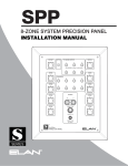
Outdoor Antenna Grounding—If an outside antenna or cable system is connected to these audio products, be sure the
antenna or cable system is grounded so as to provide some protection against voltage surges and built-up static charges. Section 810
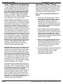
of the U.S. National Electrical Code, and Section 54 of the Canadian Electrical Code, provide information with respect to proper grounding of the mast and supporting structure, grounding of the lead-in wire to an antenna discharge unit, size of grounding conductors, location of antenna-discharge unit, connection to grounding electrodes, and requirements for the grounding electrode. See the grounding
diagram (right).
Overloading—Do not overload wall outlets and extension cords, as this could result in fire or electric shock.
Object and Liquid Entry—Never insert objects of any kind through
the openings of these appliances, as they may touch dangerous voltage points
or short-out parts that could result in a fire or electric shock. Care should be
taken so that objects do not fall and liquids are not spilled into the appliance
through openings in the enclosure.
Servicing—Do not attempt to service these appliances yourself, as opening or removing covers may expose you to dangerous voltage or other hazards.
Refer all servicing to qualified service personnel.
Damage Requiring Service—These appliances should be serv-
Grounding
Diagram
ANTENNA
LEAD-IN WIRE
GROUND
CLAMPS
ANTENNA LEAD-IN WIRE
(CEC SECTION 54-200)
(NEC SECTION 810-20)
ELECTRIC
SERVICE
EQUIPMENT
iced by qualified service personnel when:
• A power supply connection or a plug has been damaged or
NEC - NATIONAL ELECTRICAL CODE
• If liquid has been spilled into the appliance or objects have fallen into the
CEC - CANADIAN ELECTRICAL CODE
appliance or
• The appliance has been exposed to water or moisture or
• The appliance does not appear to operate normally or exhibits a marked change in performance or
• The appliance has been dropped or the enclosure damaged.
GROUNDING CONDUCTORS
(CEC SECTION 54-200)
(NEC SECTION 810-21)
GROUND CLAMPS
POWER SERVICE GROUNDING
ELECTRODE SYSTEM
(CEC SECTION 10-700)
(NEC ARTICLE 250, PART H)
Replacement Parts—When replacement parts are required, be sure the service technician has used replacement parts specified by the manufacturer or that have the same characteristics as the original part. Unauthorized substitutions may result in fire, electric shock, or other hazards. The Master Control Unit battery should be replaced only after turning the power off and only by an authorized installer.
Safety Check—Upon completion of any service or repairs to this audio product, ask the service technician to perform safety
checks to determine that the audio product is in proper operating condition.
Lightning—For added protection for these audio products during an electrical storm, or when they are left unattended and unused
for long periods of time, turn off the circuit breaker, and disconnect the antenna or cable system. This will prevent damage to the audio
products due to lightning and power-line surges.
Page 4
© ELAN Home Systems, Inc. 2004 • All rights reserved. 7/04
D1650/D1651 INSTALLATION MANUAL
ELAN HOME SYSTEMS
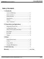
Table of Contents
1. Introduction
Thank You/ELAN Story........................................................... 2
Safety Information.................................................................. 3
System Overview.................................................................... 6
Specifications......................................................................... 6
Features.................................................................................. 7
Class ‘T’ Explained ............................................................... 8
2. Connections and Applications
Independent Stereo Zones.................................................... 9
Two Room Stereo Zones......................................................... 10
Stereo Zones with Mono Sub-Zones.................................... 11
Mono Zones........................................................................... 12
Bus Mode............................................................................... 13
Triggers................................................................................... 14
3. Setup
Setting Channel Levels.......................................................... 15
Lockout................................................................................... 15
Factory Default....................................................................... 16
Changing LED Brightness..................................................... 16
4. Troubleshooting.................................................................... 17
Warranty.........................................................................................Back Page
© ELAN Home Systems, Inc. 2004 • All rights reserved. 7/04
Page 5
D1650/D1651 INSTALLATION MANUAL
ELAN HOME SYSTEMS
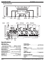
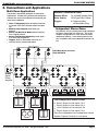
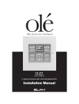
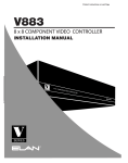
System Overview
CH I6
SIGNAL
PRESENCE
LEDS
FRONT
BACK
POWER
SWITCH
CHANNEL
SELECT
DISPLAY
BUS A
BUTTON
LINE INPUTS/
LOOP OUPUTS
1-8
Specifications
Audio Section
Output Power (16 CH Stereo) . . . . . . . 60Wrms @ 4 ohms/CH
Output Power (16 CH Stereo) . . . . . . . 45Wrms @ 8 ohms/CH
Frequency Response . . . . 20 Hz to 20 kHz, -.3dB into 8 ohms
Full Power Bandwidth . . . . . . . . . . . . . . . . . . . 10Hz to 50 kHz
Signal-To-Noise . . . . . . . . . . . . . . . . . . . . > 102db (A-weighted)
Channel Separation . . . . >-70dB (channel to channel @ 1 kHz)
Total Harmonic Distortion . . . . . . . . . . . . . . . . . . . . . . < .04%
Dynamic Headroom . . . . . . . . 120W @ 4ohms, 90W @ 8 ohms
Intermodulation Distortion . . . . . . . . . . . . . . . . . . . . . < 0.1%
Voltage Gain (AV) . . . . . . . . . Continuously Variable from 0 - 24
Slew Rate . . . . . . . . . . . . . . . . . . . . . . . . . . > 20V/microsecond
Input Impedance . . . . . . . . . . . . . . . . . . . . . . . . . . . 49 K ohms
Input Sensitivity . . . . . . . . . . . . . . . . 790Vrms (45W @ 8 ohms)
Page 6
VOLUME
DOWN/UP
BUTTONS
CHANNEL
SELECT
DOWN/UP
BUTTONS
+12V
+12VDC TRIGGER
FUSE
+12V ‘ALL ON’ TRIGGER
INPUT
OUT
TRIGGER
PAIRS
1-16
Power Rating - RMS
VOL 75
VOLUME
LEVEL
DISPLAY
BUS B
BUTTON
CHANNEL
CLIPPING
LEDS
LINE INPUTS/
LOOP OUPUTS
9-16
SPEAKER OUTPUTS 1-16
Connectors
Input/Loop Outputs . . . . . . . . . . . . . . . . . . . . Gold RCA Phono
Speaker Output . . . . . . . . . . . . . . . . . . . . . . WECO Terminators
Power
AC Power Requirements . . . . . . . . . . . . .120 VAC, 1200 Watts
Power Supply . . . . . . Ultra-high efficiency toroidal transformer
Triggers
Remote Trigger Inputs . . . . . . . . . . . . . . . 5 to 24 Volts AC/DC
Trigger Loop Output . . . . . . . . . . . . . . . . . . . . .+12VDC @0.1A
Dimensions/Weight
Dimensions . 5.25 x 17.0 x 15 (inches)/13.34 x 43.18 x 38.1 (cm)
Rack Face . . . . . . . . . . . . . 19 X 5.25 (inches)/48.26 x 13.34(cm)
Weight . . . . . . . . . . . . . . . . . . . . . . . . . . . . . . . . 50 lbs/22.68 kg
© ELAN Home Systems, Inc. 2004 • All rights reserved. 7/04
D1650/D1651 INSTALLATION MANUAL
Features
‘Class T’ Design
‘Class T’ allows the D1650 to deliver its full rated
power from all sixteen channels simultaneously and
is 90% efficient so that the amplifier does not waste
energy producing excessive heat.
Dual Stereo Bus
BUS A and BUS B inputs and outputs allow the
amplifier to be configured in dozens of different
ways to meet the demands of large audio distribution systems. Channels can be assigned to one of
two audio busses in order to be split or combined
according to situational demands.
Audio inputs can be BUS A, BUS B, Independent,
Stereo, or Mono without the use of extraneous
patch cables. Additional amplifiers can be connected from the Line outputs of the D1650 to provide
greater system expansion.
ACE™ (Automatic Clip Eliminator)
Microprocessor-controlled dynamic leveling circuit
eliminates clipping without audio degradation typical
with traditional compressor-based clipping circuits.
Each amplified output is continuously monitored for
signal clipping. Extremely fast transients are
ignored but if ACE sees a consistent clipping trend,
it turns the respective channel down by one increment. This action is repeated until no more clipping
is detected. Once clipping is absent for five seconds, ACE will slowly and unnoticeably begin to
restore the original gain settings. This translates into
accurate, high quality audio reproduction at all volume levels.
ELAN HOME SYSTEMS
Digital Volume Level Set/Lockout
All channel volume levels are matched to within
0.3dB, making volume setup easy, accurate, and
repeatable. Volume settings are stored within the
D1650's non-volatile memory upon exiting setup.
This means that settings are preserved even when
a power outage occurs.
A special multi-button key press can be used to
lock the volume settings so that they can not be
tampered with. The user may view their settings
when the system is locked, but is unable to change
them.
Advanced Amplifier Protection
Each channel of the D1650 is coupled to its respective WECO speaker terminal via a high power relay.
If the processing circuitry senses a fault condition
(over heating, shorted output, etc.), it will completely
disconnect the amplifier channel from the output
load. Faulted conditions will be indicated on the
front panel. After finding and correcting the problem
causing the fault condition, simply power the unit
OFF and back ON to restore operation.
Rack Mount Aluminum Front
Panel w/ Rugged Handles (D1651)
Amplifier mounts securely to equipment racks.
Handles are invaluable when moving, installing,
adjusting or servicing the unit.
Individual Remote Trigger Inputs/
Trigger Output
Eight +12VDC Trigger Inputs allow each pair of
channels to be powered up and muted independently. The +12VDC Trigger Output turns on and mutes
additional amplifiers.
Signal Presence and Clipping
Indicators
High-visibility blue LED display and front panel
Channel Select and Volume Adjustment controls
make setup easy. Blue Signal LEDS show when
audio is present on each input. Red Clipping LEDS
indicate distortion, and make fine tuning the amplifier very straightforward. Five blue LEDs fire downward to softly indicate Power status. The Signal
Level and Power LEDs feature adjustable brightness.
© ELAN Home Systems, Inc. 2004 • All rights reserved. 7/04
Page 7
ELAN HOME SYSTEMS
‘Class T’ Digital Technology Explained
The ultimate objective of any audio amplifier design
is to make a high fidelity amp with high efficiency
and high reliability. There are several basic audio
power amp topologies that have been developed to
attain these objectives: Class-A, Class-B, ClassAB, Class-H, Class-G and Class-D are the most
common. The D1650 utilizes proprietary Class-T
topology from Tripath™. Class T combines the
best attributes of several of these designs and minimizes deficiencies in each design, as well.
Class-A, Class-B and Class-AB amps have been
around for over fifty years. Basically, these classifications designate the amount of time that the amp’s
output devices conduct during one full cycle of a
periodic signal. Class-A amps are in a state of conduction 100% of the time. Class-B amps have a
complimentary pair of outputs, which are biased so
that each output is conducting only 50% of the time.
Class-AB amps also have complimentary output
pairs but they are biased so that each output is conducting slightly more than 50% of the time: this lowers crossover distortion. The vast majority of audio
amps in use today are Class-AB. A well-designed
Class-AB amplifier has good linearity (high fidelity)
and poor efficiency (less than 50%). Class-H and
Class-G are both voltage-supply varying techniques
which are usually applied to Class-AB type, linear
amplifiers. These techniques give marginal
improvement in efficiency at the cost of a more
complex and less reliable power supply.
Class-D amplifiers use output devices which switch
on and off at a fixed frequency. This frequency is
usually more than ten times higher than the highest
frequency to be amplified. A passive filter reconstructs the wave form passing through the amplifier
and removes switching artifacts that distort sound.
Class D amplifiers use output devices that are either
ON or OFF; never in a state of mid-conduction. This
mid-conduction state is what causes linear switching amplifiers to be as inefficient as they are (less
than 50% efficiency). Class D amplifiers are approximately 85% efficient: a 35% increase!
D1650/D1651 INSTALLATION MANUAL
Advantages of Class T Design
Class T is a combination of Adaptive Digital Signal
Processing and Spread-Spectrum Switching. This
design takes the efficiency of a Class D amp and
combines it with the fidelity of a Class AB amplifier
by dramatically improving signal integrity.
Class T offers the following improvements over
Class D:
1. Class D has a fixed switching input. Class T
has an adaptive switching frequency which is
dependent upon both input signal frequency
and magnitude. Switching artifacts are
removed in this way, reducing distortion. The
switching signal is constantly being optimized
to match the input signal in order to yield the
highest possible fidelity.
2. Class D amplifiers have nominal switching frequencies between 200kHz and 300kHz which
creates artifacts in the 20 to 50kHz audio band.
This can be heard as audible noise. Class T
amplifiers have nominal switching frequencies
between 600kHz and 700kHz; artifacts from this
frequency are not audible.
3. Class T design constantly monitors the output
transistors and adaptively corrects for varia
tions between and within these transistors. The
Class T design also monitors and corrects for
ground bounce that the transistors produce
when switching large currents.
4. Typical power efficiency with a Class T amplifier
is 85% (unreachable by class A-B amps).
Typical THD + Noise is less than 0.04%
(unreachable by Class D amps.)
Truly the best of both worlds!
As mentioned, each of these amplifier designs has
drawbacks. Class D amps have tendencies toward
high distortion rates. Crossover distortion, ground
bounce, and high frequency artifacts create most of
the distortion in these designs. Imperfectly
matched transistors lead to inexact ON/OFF timing
results and crossover distortion issues. Ground
Bounce caused by high-current switching of the
output transistors manifests itself as noise on the
audio output. In some Class D amplifiers, this highfrequency noise is not completely filtered out,
resulting in high frequency distortion.
Page 8
© ELAN Home Systems, Inc. 2004 • All rights reserved. 7/04
ELAN HOME SYSTEMS
D1650/D1651 INSTALLATION MANUAL
2. Connections and Applications
Multi-Room Applications
The D1650 is specifically designed for multi-room
applications. Virtually every feature was selected to
enhance the multi-room experience and simplify the
multi-room installation:
Class T Topography allows all sixteen channels
to coexist in the same chassis without overheat
ing.
Buffered Loop Outputs allow sharing of
sources.
Stereo and Mono Bus Modes make configura
tion a logical process.
Sixteen Independent Channels provide audio
to a house full of speakers.
Triggers allow for automated functions on a
zone-by-zone or system-wide basis.
WIRING CONSIDERATIONS
Speaker Wires
Audio Cables
Triggers
14-18 AWG Speaker Wire
RCA Type Patch Cables
2 Conductor Wire
w/ Mono Mini-Plug
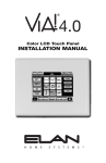
Independent Stereo Zones
The D1650 is set up to easily power eight independent stereo zones right out of the box. This is the
standard configuration for most multi-zone audio
distribution systems. In the drawing below, each
pair of speakers will have independent volume control.
ELAN Multi-Room Controller
ZONE OUTPUTS
D1650
Digital
Power
Amplifier
Four Independent Stereo Zones
ZONE 3
ZONE 1
ZONE 2
ZONE 4
© ELAN Home Systems, Inc. 2004 • All rights reserved. 7/04
Zone 1 Output to Line Inputs 1 & 2
Zone 2 Output to Line Inputs 3 & 4
Zone 3 Output to Line Inputs 5 & 6
Zone 4 Output to Line Inputs 7 & 8
Each Zone’s Speakers Have Independent Volume
Speaker Outputs Coincide w/ Line Inputs
Page 9
D1650/D1651 INSTALLATION MANUAL
ELAN HOME SYSTEMS
Two Room Stereo Zone
By using the D1650’s Audio Loop, an additional pair of speakers can be added to a zone.
In this example, both pairs of speakers will ramp volume up and down simultaneously.
ELAN Multi-Room Controller
ZONE OUTPUTS
D1650
Digital
Power Amplifier
Two Room Stereo Zone
Zone 1 Output to Line Inputs 1 & 2
Line Outputs 1 & 2 to Line Inputs 3 & 4
All Speakers Volume Ramps Up/Down Together
Speaker Outputs Coincide w/ Line Inputs
Page 10
© ELAN Home Systems, Inc. 2004 • All rights reserved. 7/04
ELAN HOME SYSTEMS
D1650/D1651 INSTALLATION MANUAL
Stereo Zones w/ Mono Sub-Zones
Use the Loop Out Jacks and an RCA ‘Y’ cable to create Mono sub-zones with Stereo zones. This application is perfect for large rooms with smaller rooms attached such as a Master Bedroom/Master Bath or Kitchen/Laundry Room.
ELAN Multi-Room Controller
ZONE OUTPUTS
D1650
Digital
Power Amplifier
Stereo Zone w/ Mono Sub-Zone
Zone 1 Output to Line Inputs 1 & 2
Line Outputs 1 & 2 to RCA ‘Y’ Cable
RCA ‘Y’ Cable to Line Input 3
All Speakers Volume Ramps Up/Down Together
Speaker Outputs Coincide w/ Line Inputs
© ELAN Home Systems, Inc. 2004 • All rights reserved. 7/04
Page 11
D1650/D1651 INSTALLATION MANUAL
ELAN HOME SYSTEMS
Mono Zones
Use mono zones in areas where there is no distinct, stationary listening area such as hallways, L-shaped rooms,
kitchens, and outdoor areas. The use of mono zones also increases the capacity of the amplifier...up to sixteen
mono areas can be powered from one D1650.
In this example, four channels of the D1650 are configured in mono to run four speakers
“Y” L & R
Zone Out
to create
a mono
signal
ELAN Multi-Room Controller
ZONE OUTPUTS
D1650
Digital
Power Amplifier
Four Room Mono Zone
ZONE 1 / Variable / Mono
Page 12
Zone 1 Output to RCA ‘Y’ Cable
RCA ‘Y’ Cable to Line Input 1
Line Output 1 to Line Input 2
Line Output 2 to Line Input 3
Line Output 3 to Line Input 4
All Speakers Volume Ramps Up/Down Together
Speaker Outputs Coincide w/ Line Inputs
© ELAN Home Systems, Inc. 2004 • All rights reserved. 7/04
ELAN HOME SYSTEMS
D1650/D1651 INSTALLATION MANUAL
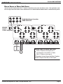
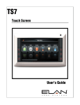
Bus Modes
This example shows two “Wide Coverage Zones,”
one using Variable Outputs from an ELAN MultiZone Controller so that all speakers ramp volume
up/down together, the other using the Fixed output
from an ELAN Multi-Zone Controller and High Power
Volume Controls so that each area has independent
volume up/down control.
The D1650’s unique Bus Mode feature allows multiple amp Inputs to be internally configured to several
different Outputs. This increases the amp’s flexibility without the use of extraneous RCA patch cables.
Using Bus A, a signal that is sent into Input 1 will
come out Speaker Outputs 3,5, and 7. Signals sent
to Input 2 will be routed to Outputs 4, 6, and 8.
Using Bus B, a signal that is sent into Input 9 will
come out Speaker Outputs 11,13, and 15. Input 10
will be sent to Speaker Outputs 12,14, and 16.
Var
Fixed
ELAN Multi-Room Controller
ZONE OUTPUTS
Press
“BUS A”
USE VOLUME CONTROLS RATED
FOR 50 WATTS RMS OR HIGHER!
Press
“BUS B”
Zone 1 is a Variable Wide Coverage Zone
Zone 2 is a Fixed Wide Coverage Zone
Zone 1 Output to Line Inputs 1 & 2
Set Zone 1 to VARIABLE on Multi-Zone Controller
Press BUS A Button
Speaker Outputs 1-8 now assigned to Zone 1
All Speakers Volume Ramps Up/Down Together
Zone 2 Output to Line Inputs 9 & 10
Set Zone 2 to FIXED on Multi-Zone Controller
Press BUS B Button
Speaker Outputs 9-16 now assigned to Zone 2
Connect Each Pair of Speaker Outputs to a High Power
Volume Control
All Speaker Pairs Volume Ramps Separately w/ High
Power Volume Controls.
© ELAN Home Systems, Inc. 2004 • All rights reserved. 7/04
Page 13
D1650/D1651 INSTALLATION MANUAL
ELAN HOME SYSTEMS
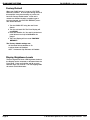
Triggers
Each channel pair of the D1650 has its own Remote
Turn On/Muting circuit. Individual channel pairs can
be turned on or muted independently of any others.
An “ALL ON” port allows the entire amp to turn on
and mute as one unit. The 12 Volt DC Trigger Out
can be used to turn-on other equipment, additional
amps, or to perform automated functions desired by
the user. The Front Display of the D1650 will show
“MUTED!” when a channel is in Mute.
application gives additional control in advanced
systems. Examples include: Zone Specific Trigger
Outputs from an ELAN Multi-Zone Controller, multiple A/V receivers triggering separate D1650 inputs,
or outboard sensors located in certain areas to trigger specific inputs of the D1650.
+12VDC TRIGGER OUT
D1650
TRIGGER
OUT
ALL ON
SOURCE
TRIGGER
OUT
+12V TRIGGER INPUTS
+12VDC
TRIG OUT
TRIGGER IN
(ADDITIONAL AMP)
TRIGGER
IN
D1650 Turns On Additional Amp w/ +12VDC Trigger Output
TRIGGER
OUT
Single Source Mutes/UnMutes All Channels Simultaneously
To Mute/Un-Mute the entire amplifier as one entity,
simply connect a system-wide 3-24 Volt AC or DC
Triggering Source to the ALL ON Trigger Input.
Examples of triggering sources include an ELAN
Multi-Zone Controller’s SYSTEM TRIGGER OUT or
REMOTE OUT, an A/V receiver’s switched outlet
connected to a power supply, or a +12VDC TRIGGER OUT from another ELAN D Series amplifier.
Specific Stereo Pair Triggers
ZONE TRIGGER OUTPUTS
1
2
3
4
5
6
Whenever the D1650 is powered On, the +12VDC
TRIGGER OUT becomes active. As the name
implies, this output sends a +12VDC 100 mA signal
to other devices utilizing a trigger. Examples of
proper usage of the +12VDC TRIGGER OUT include
muting/un-muting another D Series amplifier, Trigger
the switched outlets of a ZPower Controller, or triggering an IR sequence using VIA!® products.
TRIGGER INPUTS ACCEPT
3 TO 24 Volts AC or DC
ELAN Multi-Zone Controller
ZONE TRIGGER OUTPUTS
(Zones 1-3 Shown)
Multi-Zone System Mutes/UnMutes Each Pair of Channels Independently
To Mute/Un-Mute specific stereo pair inputs, a
zone-specific Triggering Source can be used. As in
the ALL ON example, any 3-24 Volt AC or DC source
may be used to trigger these specific inputs. This
Page 14
© ELAN Home Systems, Inc. 2004 • All rights reserved. 7/04
ELAN HOME SYSTEMS
D1650/D1651 INSTALLATION MANUAL
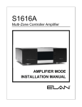
3. Setup
DISPLAY
CH I6
Signal
Presence
LEDs
Channel
Select
Display
Channel
Select
Down/Up
Buttons
Setting Channel Levels
The leftmost display on the front of the D1650
shows which channel is selected for adjustment.
Pressing C+ or C- will cycle through each individual
channel. Once a channel is selected, use the V+ and
V- buttons to adjust the channel’s Volume Up or
Down from 0 to 100 (50 is Factory Default).
Each amp channel can be individually adjusted from
the front panel. Pressing the C button will cycle
through all the inputs on the amplifier — both Left
and Right channels can be adjusted independently.
The C button to the left cycles downward, the one
on the right cycles upward. When the desired channel is displayed on the front panel, use the V buttons. Again, the V button to the left lowers the volume for that channel, the one on the right raises
the volume.
Set the levels by lowering them all the way down,
then raise the volume of any keypads or volume
controls to maximum. Slowly adjust Volume Up for
this channel until the red clipping LEDS start to light
up, then drop the level one or two clicks. Follow
this procedure for all channels.
Please Note: Whenever the Front Display is lit (during volume adjustment, for example), ACE clipping
elimination circuitry is disabled.
© ELAN Home Systems, Inc. 2004 • All rights reserved. 7/04
VOL 75
Volume
Down/Up
Buttons
Volume
Level
Display
Channel
Clipping
LEDs
Lockout Mode
The Lockout feature is designed to disable all front
panel functions. Use this feature once the system is
fine-tuned and ready-to-go. By locking the system’s front panel, prying hands cannot ruin carefully
set level adjustments or overdrive speakers.
To place the D1650 in Lockout Mode:
1. With the Front Display dark, Press C- and Vsimultaneously.
2. Continue pressing C- and V-. The Front Display
will show the Volume setting momentarily.
3. Four seconds later, the Front Display will read
LOCK. Release the buttons.
4. Follow the same procedure to Unlock the D1650.
Please Note: If the user tries to change settings
while in Lockout Mode, the Front Display will read
“VOLUME LOCK IS ON”.
THERE IS NO BENEFIT FROM TURNING
THE AMPLIFIER'S LEVELS PAST THE
POINT WHERE THEY CAUSE THE RED
CLIPPING LEDS TO LIGHT UP.
Page 15
ELAN HOME SYSTEMS
D1650/D1651 INSTALLATION MANUAL
Factory Default
When your D1650 arrives, it is set to a FACTORY
DEFAULT condition. At some point during the life of
this amplifier it may be necessary to put the unit
back into Factory Default mode. If this unit is
moved to a different location or speaker type or
load are changed, the FACTORY DEFAULT procedure should be used:
1. Turn the D1650 OFF using the rear Power
Switch.
2. Turn the unit back ON. The Front Display will
read ELAN.
3. Press and hold C+, C-, V+, and V- (all the front
panel buttons at once) while ELAN is displayed.
4. The Front Display will now read “FACTORY
DEFAULT”.
The Factory default settings are:
All channels Volume defaults to 50.
Lockout feature is Disabled.
ACE ™ Automatic Clip Eliminator is Enabled.
Display Brightness Levels
The blue Signal and Power LED brightness levels on
the Display can be increased or decreased from the
Front Panel. Press and hold C+ and V+ to cycle
between High, Low, and Off. The red Clipping LEDs
will remain at full illumination.
Page 16
© ELAN Home Systems, Inc. 2004 • All rights reserved. 7/04
ELAN HOME SYSTEMS
D1650/D1651 INSTALLATION MANUAL
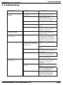
4. Troubleshooting
SYMPTOM
CAUSE
SOLUTION
No Audio From One or More
Channels
1. Loose/Bad Speaker Cable
Connection
2. Break/Short in Speaker Cable
Check Cable Ends at Binding
Posts and Speaker Terminals
Check Continuity of Each Speaker
Cable Using Multimeter.
If Short or Open is Indicated, Check
Wiring for Proper Connections.
Swap with Known Good Speaker
3. Speaker is defective
"MUTED!" Flashes on Display,
Then Volume Setting
4. RCA Patch Cable Defective
Swap with Known Good Patch
Cable.
5. Source not Sending Audio
Verify Source is Powered Up and
Playing. Check any Tape Monitor
Settings on A/V Receiver.
Make sure triggering device’s
remote output is connected and
producing voltage.
Find short or low-impedance
condition. Correct overheating or
AC power issues. Once issue is
found and resolved, cycle power to
D1650. This condition could be
caused by 1. 2.,3., and/or 4 above.
Plug All Sources into Same AC
Outlet.
Channel is in MUTE
"ERROR!" Message Displayed Amplifier in Protection Mode
on Front Panel
Audio “Hum”
1.Ground Potential Difference
Between Source Components
(Ground Loop)
2. Faulty/Damaged Cables
3. Faulty Wiring
Test AC Outlet Using Ground
Tester.
Check Source Equipment Cables
For Damaged Cables and Faulty
Connections.
Make Sure Any Volume Controls
Are Not Hooked Up Backwards.
Check for Shorts in Wiring
(See item 2 in “No Audio…”)
Distorted Audio at Normal
Volume Levels
1. Input Gain Too High
2. Defective/Incompatible
Speaker
3. Volume Control Miswired
© ELAN Home Systems, Inc. 2004 • All rights reserved. 7/04
Reduce Gain to the Channel in
Question. Ensure Red Clipping
LEDs are not Pulsing or On
Constantly.
Check for Physical Damage to
Speaker
Check Power Ratings on Speaker
Do Not use Speakers Rated for
Less than 50 Watts RMS.
Check for Proper Input/Output
connections at Volume Control.
INPUT Comes from Amplifier,
OUTPUT Goes to Speakers.
Page 17
D1650/D1651 INSTALLATION MANUAL
ELAN HOME SYSTEMS
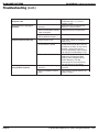
Troubleshooting (cont.)
Audio is Unclear, Bass
Response Low
Speakers Out of Phase
Incorrect Source Playing on
Speakers
1. BUS A and/or BUS B buttons
pressed.
Amplifier Will Not Power Up
2. Source Connected to Wrong
Input of Amplifier
Verify Source Input Connections.
3. Speakers Connected to
Wrong Speaker Outputs
Verify Speaker Connections.
1. Power Switch is OFF
Turn it ON. Switch is Located on
Back of Unit.
2. Circuit Breaker Tripped
1. Impedance-Match Settings
Incorrect
ELAN Recommends the D1650 be
Installed on its Own 15 Amp Circuit
Breaker. Placing this Unit on a
Circuit Populated by Other Devices
can Cause Circuit Breakers to Trip.
Ensure That Any Remote Turn On
Cables are Connected At Both
Ends. A Cable Plugged into the
D1650 Remote In, but Not
Connected to a Sources Remote
Out will Remain in Mute Mode.
Set Impedance-Match Settings
Correctly.
2. Using Incompatible Volume
Control
Use Volume Controls Rated for 50
Watts or Higher.
3. Remote Turn-On Miswired
Audio Very Distorted in Areas
Using Volume Controls
Page 18
Verify that + of Amplifier goes to +
of Speaker (and – to -) on ALL
Speaker Leads.
Make sure BUS A and/or BUS B
buttons in correct position.
© ELAN Home Systems, Inc. 2004 • All rights reserved. 7/04
D1650/D1651 INSTALLATION MANUAL
ELAN HOME SYSTEMS
Notes:
© ELAN Home Systems, Inc. 2004 • All rights reserved. 7/04
Page 19
Limited Warranty
ELAN HOME SYSTEMS L.L.C. ("ELAN") warrants the D1650/D1651 to be free from defects in materials and
workmanship for the period of Two Years (2 Years) from date of purchase. If within the applicable
warranty period above purchaser discovers that such item was not as warranted above and promptly notifies
ELAN in writing, ELAN shall repair or replace the item at the company's option. This warranty shall not apply
(a) to equipment not manufactured by ELAN, (b) to equipment which shall have been installed by other than an
ELAN authorized installer, (c) to installed equipment which is not installed to ELAN's specifications, (d) to equipment which shall have been repaired or altered by others than ELAN, (e) to equipment which shall have been
subjected to negligence, accident, or damage by circumstances beyond ELAN's control, including, but not
limited to, lightning, flood, electrical surge, tornado, earthquake, or other catastrophic events beyond ELAN's
control, or to improper operation, maintenance or storage, or to other than normal use of service. With respect
to equipment sold by, but not manufactured by ELAN, the warranty obligations of ELAN shall in all respects
conform to the warranty actually extended to ELAN by its supplier. The foregoing warranties do not cover
reimbursement for labor, transportation, removal, installation or other expenses which may be incurred in connection with repair or replacement.
Except as may be expressly provided and authorized in writing by ELAN, ELAN shall not be subject to any other
obligations or liabilities whatsoever with respect to equipment manufactured by ELAN or services rendered by
ELAN.
THE FOREGOING WARRANTIES ARE EXCLUSIVE AND IN LIEU OF ALL OTHER EXPRESSED AND IMPLIED
WARRANTIES EXCEPT WARRANTIES OF TITLE, INCLUDING BUT NOT LIMITED TO IMPLIED WARRANTIES
OF MERCHANTABILITY AND FITNESS FOR A PARTICULAR PURPOSE.
ATTENTION: TO OUR VALUED CONSUMERS
To ensure that consumers obtain quality pre-sale and after-sale support and service, ELAN Home
Systems products are sold exclusively through authorized dealers. ELAN products are not sold
online. The warranties on ELAN products are NOT VALID if the products have been purchased
from an unauthorized dealer or an online E-tailer. To determine if your ELAN reseller is
authorized, please call ELAN Home Systems at (859) 269-7760.
2428 Palumbo Drive Lexington, KY 40509
www.elanhomesystems.com
P/N 9900486 REV: A