1
OLE2
PATENT PENDING
2-gang touchpad with interchangeable films
Installation Manual
®
ELAN HOME SYST E M S
INSTALLATION MANUAL
OLÉ2
Contents
Introduction ................................................................ 3-10
Features ........................................................................... 4
Installation & Usage Tips .......................................... 5
Cleaning the Touchscreen ........................................ 6
Specifications ................................................................. 7
Power Consumption/Maximum Load per ELAN
Multi-Room Controller ................................................ 7
OLÉ2 Front ..................................................................... 8
OLÉ2 Rear ...................................................................... 9
Overlays .......................................................................... 10
System Design, Installation and
Connections .............................................................. 11-27
Planning .......................................................................... 11
Installation .................................................................... 11
Pre-Wire ................................................................... 11
Rough-In .................................................................. 12
Mounting Height ................................................... 12
Changing Overlays ............................................... 13
Connectors/Pinout .............................................. 14
RJ-45 Connector .............................................. 14
Interface Port .................................................... 15
IR Out .................................................................. 15
IR In ..................................................................... 16
Sense .................................................................. 17
System Connections ........................................... 18
Stand-Alone/Home Theater ............................ 18
Stand-Alone/Home Theater-Expanded ......... 19
ELAN System12-Z•NET (w/ PS12) ................. 20
ELAN System12-Z•NET (No PS12) ................ 20
ELAN System12-VIA!NET ................................. 21
ELAN System6-Z•NET ..................................... 22
ELAN System6-VIA!NET ................................... 23
© 2006 ELAN Home Systems • All Rights Reserved
Page 1
OLÉ2
INSTALLATION MANUAL
ELAN HOME SYST E M S
Contents (Cont.’d)
ELAN Z• System-ZNET (w/PZ6-Three or Fewer
Touchpads) ............................................................ 24
ELAN Z• System-Z•NET (Four or More
Touchpads) .......................................................................... 24
ELAN Z• System-Z•NET (No PZ6-Three or Fewer
Touchpads) ............................................................ 25
ELAN Z• System-VIA!NET (w/ PZ6) .................. 26
ELAN Z• System-VIA!NET (No PZ6) ................. 27
Programming ............................................................ 28-29
To Download a VIA!®TOOLS Project ..................... 28
Downloading to Multiple OLÉ2s ........................... 28
Feature Enable/Disable ............................................ 29
Warranty ............................................................ Back Page
Page 2
© 2006 ELAN Home Systems • All Rights Reserved
ELAN HOME SYST E M S
INSTALLATION MANUAL
OLÉ2
Introduction
The OLÉ2 (patent pending) Film Interactive Touchpad (FIT) is a double-gang,
in-wall system controller that uses a touch overlay in lieu of hard buttons to
perform all functions normally associated with a keypad. Source and system
control icons and function names are printed on interchangeable backlit film
transparencies. Each icon or function name corresponds to an active “hot
spot” that issues a control command and gives both audible and visual confirmation to the user when pressed.
Multiple IR commands, or ‘Sequences’, can be issued from a single press
of any button on any template. The touchpad features a 4-line, 1.2" color
OLED to provide source, system and programming feedback to the user.
Programming is accomplished with ELAN’s VIA!TOOLS Setup Software and
is done through a direct link from a computer to the mini-USB Download Port
on the front of the unit.
The OLÉ2 is designed to use easily installed Overlays that are available in
a wide variety of configurations in various graphical themes to match any
functional requirements and any room’s decór. Three levels of complexity are
available to customize each touchpad, from basic functionality to advanced
system control.
Film Interactive Technology
The OLÉ2 utilizes a polyester plastic film suspended over a glass panel,
which is placed over a changeable backlit Overlay. Depressing the polyester
film with a finger allows the film to touch the glass panel underneath, generating a location signal that is read by the electronics. Each button location
(or “hot spot”) is assigned an IR or RS-232 command that controls sources
such as A/V equipment, HVAC systems, drapes, shades, lighting systems,
or even fireplaces! Each touchpad is custom-programmed to perform exactly
the functions required for each individual home, room, and/or system.
© 2006 ELAN Home Systems • All Rights Reserved
Page 3
OLÉ2
INSTALLATION MANUAL
ELAN HOME SYST E M S
Features
• Full touchpad design, no hard buttons
• Interchangeable control templates
• 1.2” color OLED (Organic LED)
• Brightness-adjusting light sensor
• Audible ‘click’ to indicate a button press (can be
disabled in software)
• Enhanced VIA!TOOLS programming
• Compatible with all current ELAN multi-room
controllers
• Stand-alone use in any IR-based system
• Z•NET/VIA!NET compatibility
• Two-way RS-232 feedback capability
• Built-in IR receiver for IR pass-through and IR
learning (can be disabled in software)
• Connectivity for Local IR Output and Remote
IR Receiver
• System Sense sequence capability
• Fits in a double-gang electrical box
• Virtually unlimited IR command sequences issued
from any button press
• Multiple wall plate options for enhanced
décor-matching
• Patent Pending
Page 4
© 2006 ELAN Home Systems • All Rights Reserved
ELAN HOME SYST E M S
INSTALLATION MANUAL
OLÉ2
Installation & Usage Tips
• When properly installed, nothing should be applying contact pressure
to the touchpad except for the operator’s finger. If something is touching the touchscreen window a false signal can be generated, causing
the touchpad not to respond a finger press (ELAN does not recommend wrapping the removable frame with wallpaper as this can cause
the aforementioned symptom). Too much force on the front of the
touchpad, or concentrated pressure, can damage the polyester film or
break the underlying glass plate.
• Avoid installation in direct sunlight or strong ultraviolet light (such as
grow lamps, plant lights, or compact flourescent lights). This can
degrade and discolor the polyester film.
• Avoid installation over heat generating devices and/or in moist areas
where condensate can form on the polyester film. Both heat and condensed moisture can affect touch screen performance.
• Avoid installation next to thermostats. The touch screen generates
heat that can effect thermostat control and readings.
• Avoid applying any foreign objects, such as adhesive labels, on the
touchscreens polyester film. This can release chemicals that can discolor the clear film.
• The touchpad should not be mounted near electronics that emit radio
frequencies or electromagnetic interference (such as the deflection
circuits of CRT monitors, light dimmers, and some power supplies)
• The edge of the touchpad has exposed sharp glass. Be careful when
handling the assembly in order to avoid injury.
© 2006 ELAN Home Systems • All Rights Reserved
Page 5
OLÉ2
INSTALLATION MANUAL
ELAN HOME SYST E M S
Cleaning The Touch Screen
To clean the polyester film, first use a soft dry cloth to remove contamination.
If dust or smudges are still present, use a damp cloth that has been squeezed
of excess water to remove the contaminant. If contaminants are still present,
use a non-abrasive cleaner or detergent to clean the polyester film. Use of
strong chemicals and/or some cleaning agents may discolor the polyester
film. The following cleansers have been tested and approved for cleaning an
OLÉ2 Touchpad:
• Windex® Glass Cleaner
• Formula 409® Cleaner
• Mr. Clean®
The following substances have also been tested and shown to have no adverse effects to the touchpad’s polyester film:
• Coffee
• Paraffin based grease
• Tea
• Ammonia
• Ketchup
• Carbureter cleaner
• Mustard
• Ethanol
• Tomato Juice
• Acetone
• Lemon Juice
• Hydro-seal®
• Hand Lotion
• Nitric Acid <10%
• Bleach
• Toluene
• 10W40 motor oil
• Hydrochloric Acid <10%
• Turpentine
• Methyl ethyl ketone
• Brake Fluid
• Ethyl acetate
• Wisk®
• Cyclohexanone
• Diesel oil
• Xylene Dimethyformamide
• Lube grease
• 1.1.1 Trichlorethane Diethyl ether
• Copper based grease
• Sodium hydroxide <10%
Page 6
© 2006 ELAN Home Systems • All Rights Reserved
ELAN HOME SYST E M S
INSTALLATION MANUAL
OLÉ2
Specifications
Viewing Angle .......................... 180° up/down,180° left/right
Operating Temp. ..................... 32°F-104°F / 0°C-40°C
OLED Display ........................... Type: 1.2” Organic LED (OLED)
Colors: 65K
Resolution: 96 pixels (W) x 64 pixels (H)
Connections ............................. System Port: RJ-45
Interface Port: 5-position screw terminal
Download Port: Mini USB
Wiring Requirements ............ Cat-5
Power Requirements............. 12VDC/150mA or 16VDC/150mA
Dimensions (w/ Wall Plate) ..... ( i n. ) 4 5/8(W) x 4.5/8(H) x 1 3/16(D)
(mm) 117(W) x 117(H) x 30(D)
Dimensions (w/o Wall Plate) .... ( i n. ) 4 7/16(W) x 4 7/16(H) x 1 1/8(D)
(mm)112(W) x 112(H) x 26(D)
Fits in 32 cu in. double-gang electrical box
Weight ........................................ 14 oz./0.4kg
Shipping Weight ..................... 16 oz./0.45kg
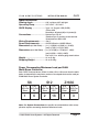
Power Consumption/Maximum Load per ELAN
Multi-Room Controller
Each OLÉ2 Touchpad draws 150mA in either 12V or 16V mode. Use the table
below to determine the maximum number of touchpads that can be used per
ELAN Multi-Room System Controller.
S6
S12
Z•630
# of
# of
OLÉs Per OLÉs Per
Zone
S6
# of
# of
OLÉs Per OLÉs Per
Zone
S12
# of
# of
OLÉs Per OLÉs Per
Zone
Z•630
1
6
2
16
1
3
Note: See System Connections for specific recommendations when an application requires exceeding the above Maximum loads.
© 2006 ELAN Home Systems • All Rights Reserved
Page 7
OLÉ2
INSTALLATION MANUAL
ELAN HOME SYST E M S
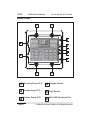
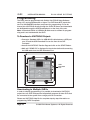
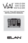
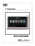
OLÉ2-Front
1
1
3
2
6
5
4
2
3
1
1
1
Mounting Screw (X 4)
4
Program Button
2
Overlay Hinge (X 2)
5
Light Sensor
3
Overlay Screw (X 2)
6
Mini USB Download Port
Page 8
© 2006 ELAN Home Systems • All Rights Reserved
ELAN HOME SYST E M S
INSTALLATION MANUAL
OLÉ2
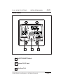
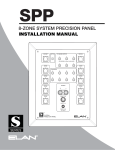
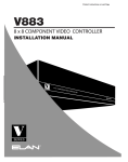
OLÉ2-Rear
1
2
1
Z•NET/VIA!NET Switch
2
System RJ-45 Jack
3
Interface Port
3
© 2006 ELAN Home Systems • All Rights Reserved
Page 9
OLÉ2
INSTALLATION MANUAL
ELAN HOME SYST E M S
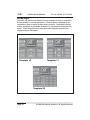
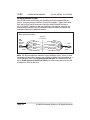
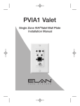
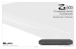
Overlays
The OLÉ2 can utilize three different Overlay templates in order to customize
its functionality for various applications. Each template is available in various Motifs in order to match a wide variety of decors. Each Motif contains
a Basic (Template 13), Moderate (Template 17), and Advanced (Template 25)
layout. These designations are important when designing a system and
programming the touchpads.
Template 17
Template 13
Template 25
Page 10
© 2006 ELAN Home Systems • All Rights Reserved
ELAN HOME SYST E M S
INSTALLATION MANUAL
OLÉ2
System Design, Installation and
Connections
Planning
Before installing the OLÉ2, it is essential to have a detailed and accurate
system design. Talk with the homeowner to make sure all expectations and
design goals are explored. The first step to a good design is to map the system. It is advisable to mark up a copy of the house floor plan with speaker,
keypad, touch panel, volume control, and equipment locations etc. Make
sure that all locations are decided upon before pre-wiring commences so
that all necessary wiring and installation hardware is in place.
It is essential that ALL system components are accounted for prior to the
pre-wire stage. After establishing design goals with the homeowner, make a
detailed list of all components. Include source equipment, keypads, touch
panels, volume controls, amplifiers, communications gear, etc. Gather up
any IR remote controls that may be necessary for final programming, or
ensure that the IR codes for all equipment to be installed are available in the
VIA!TOOLS IR Library.
Installation
The OLÉ2 is designed to fit into a standard 32 cu. in. two-gang electrical box.
Consult local building codes for specifics in your geographic area.
Pre-Wire
The OLÉ2 requires power, control, and status to function correctly. Each
Touchpad has an RJ45 jack on the back to allow for easy connection. Run
Cat-5 wire from the main central equipment location (head-end) to the location where each Touchpad will be installed.
ELAN recommends the use of C45P RJ-45-to-pigtail interface cables when
installing Touchpads. The RJ-45 pinout for each ELAN multi-room controller
is included in the manual for that particular product.
Note: Use of wire other than Cat-5 may produce undesired results (IR bandwidth may be narrowed or interference may occur).
Maximum wire run is 500 feet.
© 2006 ELAN Home Systems • All Rights Reserved
Page 11
OLÉ2
INSTALLATION MANUAL
ELAN HOME SYST E M S
Rough-In
Roughing-in the OLÉ2 requires careful attention to the design plan made
previously. See System Design & Applications for a list of things to factor in
to specific mounting locations before deciding exactly where to place
the unit. In order to avoid Electro-Magnetic Interference (EMI), do not mount
Touchpads close to light dimmers. Leave at least one stud-bay open
between Touchpads and dimmers (leave more space if multiple dimmers
are present). Avoid installing OLÉ Touchpads in areas that will receive direct
sunlight. Sunlight can flood the IR receiver and make the system inoperative.
Do not mount Touchpads outdoors! Corrosion will damage them. ELAN does
not warrant OLÉ Touchpads for outdoor use.
Mounting Height
For proper viewing, mount the OLÉ2 56-60 inches from the floor to the bottom of the frame. This will provide optimum viewing for the largest number
of people.
Page 12
© 2006 ELAN Home Systems • All Rights Reserved
ELAN HOME SYST E M S
INSTALLATION MANUAL
OLÉ2
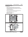
Changing Overlays
To change Overlays:
1. Remove the magnetic Wall Plate from the front of the unit.
2. Remove the two Overlay screws on the right side of the unit.
3. Use the notch located in the upper right-hand corner to open the
Touch Screen (45° max.).
4. Remove the existing Overlay.
5. Place the new Overlay into the holder of the transparent Touch
Screen making sure of the proper orientation.
6. Close the Touch Screen.
7. Replace the two Overlay screws.
8. Replace the Wall Plate.
Screw
Screw
Overlay
Touch
Screen
Place Overlay
in Holder on
Touch Screen
© 2006 ELAN Home Systems • All Rights Reserved
Page 13
OLÉ2
INSTALLATION MANUAL
ELAN HOME SYST E M S
Connectors/Pinout
The OLÉ2 has a System RJ-45 connector and a five pin Local/AUX connector which each perform specific functions. All applications will use the RJ-45
connector, while certain situations will require the use of the Local/AUX connector.
RJ-45 Connector
The System RJ-45 provides required functionality for all system types. Use
this connector when the OLÉ2 is used in an ELAN Multi-Room Controllerbased system (ELAN S or Z• System). This connector must also be used
in Stand-Alone systems and systems with Local applications. Use ELAN
Standard Pinout configuration.
Insert wires in this order:
Blue
White/Blue
Orange
White/Orange
Green
White Green
Brown
White/Brown
OLÉ2
RJ-45 Connector
ELAN ZNET RJ-45 Pin-Out
PIN # COLOR CODE
FRONT
Use ZNET
when NOT
using a
VIA!-SC4
or
VIA!2-SS1
1
2
3
4
5
6
7
8
TAB
BLUE
WHITE/BLUE
ORANGE
WHITE/ORANGE
GREEN
WHITE/GREEN
BROWN
WHITE/BROWN
Sense
IR OUT
Local IR
RS-485+
RS-48512VDC+
GND
N/C
CABLE
ELAN VIA!NET RJ-45 Pin-Out
PIN # COLOR CODE
FRONT
Use VIA!NET
when
using a
VIA!-SC4
or
VIA!2-SS1
1
2
3
4
5
6
7
8
TAB
BLUE
WHITE/BLUE
ORANGE
WHITE/ORANGE
GREEN
WHITE/GREEN
BROWN
WHITE/BROWN
Sense
IR OUT
RS-485RS-485+
GND
16VDC+
GND
16VDC+
CABLE
Page 14
© 2006 ELAN Home Systems • All Rights Reserved
ELAN HOME SYST E M S
INSTALLATION MANUAL
OLÉ2
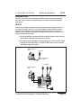
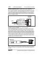
Interface Port
Use this connector when utilizing the OLÉ2’s Local Control features such
as Local source control, Local IR Sensors, or Sense-enabled automated
sequences.
IR OUT
The Local IR Output is typically used to control a device that is not part of
the main IR system, such as a TV or DVD player located within the same
room as the touchpad or an ELAN Electronic Volume Control such as a
VSE100. IR is routed to an emitter or IR distribution block connected to the
Local IR Output in two ways:
1. Any IR signal that is received from the Local IR Input is sent out both
the Local IR Output and the System IR Output.
2. IR signals may be specified in programming as “Local” and be routed
through the Local IR Output. See VIA!TOOLS “Help” file for specific
information about IR routing.
OLÉ2 Interface
Port
IR Emitter
IR + = White Stripe
GND = Black
IR Emitters
OLÉ2 Interface
Port
IR
RCVR
STATUS IN
5~24V D C
J8
HP ON
HP ON
NET ON
LP ON
LP ON
NET OFF
J6
J5
J4
IR IN
IRD4
ST OUT
Amplified IR Distribution Block
GND
J7
LP/HP IR OUT
IR OUT
+12V
12V DC
REGULATED
IRD4
Amplified IR
Distribution Block
© 2006 ELAN Home Systems • All Rights Reserved
Page 15
OLÉ2
INSTALLATION MANUAL
ELAN HOME SYST E M S
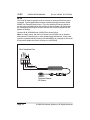
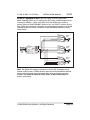
IR IN
The Local IR Input is typically used to connect an external IR sensor to the
touchpad. Typical applications include a plasma-friendly IR sensor (ELAN
IRS8EP, for example) placed near a TV, or an auxilliary IR sensor placed in
an area more convenient than the location of the touchpad. IR signals that
are received by the IR Input are sent out both the Local IR Output and the
System IR Output.
Connect IR IN, GROUND and +12VOLTS as shown below.
Note: In certain cases, the built-in IR sensor on the OLÉ2 can be flooded
with plasma TV interference or other ambient light interference In this case,
connect a plasma-friendly IR sensor (ELAN IRS8EP, for example) to the Local
IR Input and disable the built-in IR sensor in VIA!TOOLS.
OLÉ2 Interface Port
IR
G
+12VDC
IRS8EP
Extreme Plasma
IR Sensor
Page 16
© 2006 ELAN Home Systems • All Rights Reserved
ELAN HOME SYST E M S
INSTALLATION MANUAL
OLÉ2
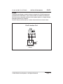
Sense
The Sense port allows a contact-closure to trigger IR or RS-232 sequences
programmed in VIA!TOOLS. Use a motion sensor to activate a contact-closure and cause automated actions such as system power on, drapes closed,
and lights dimmed, for example.
Connect Sense and Ground to a contact-closure device as shown below.
OLÉ2 Interface Port
+
Contact-Closure
Device
© 2006 ELAN Home Systems • All Rights Reserved
Page 17
OLÉ2
INSTALLATION MANUAL
ELAN HOME SYST E M S
System Connections
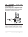
Stand-Alone/Home Theater
The OLÉ2 is ideal for use as a stand-alone (non-ELAN) system controller or
Home Theater controller. For control of a Home Theater system, the OLÉ2 is
combined with a method for IR distribution such as ELAN’s IRD4 Amplified
IR Distribution Block. Signals originate at the OLÉ2 and travel to the distribution block where they are routed to each component. In this application,
power the OLÉ2 from the IRD4’s included power supply, as shown. Place the
Z•NET/VIA!NET Switch in the “12v Z•NET” position (to the left).
Sources
OLÉ2
ELAN
C45P
White/Brown
Brown
White/Green
Green
White/Orange
Orange
White/Blue
Blue
N/C
N/C
N/C
N/C
N/C
IRD4 Amplified IR
Distribution Block
Note: The PWR2 12VDC 200mA Power Supply included with the IRD4 is
capable of supporting one OLÉ Touchpad. If additional touchpads will be
installed, then the ELAN PWR3 +12VDC 2.1A power supply should be used.
The PWR3 will support up to thirteen OLÉ Touchpads. If more than two
touchpads will be connected to the IRD4, use jumper wires to connect the
additional units prior to the connector locations on the IRD4.
Page 18
© 2006 ELAN Home Systems • All Rights Reserved
ELAN HOME SYST E M S
OLÉ2
INSTALLATION MANUAL
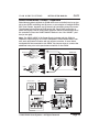
Stand-Alone/Home Theater - Expanded
Stand-alone systems (without an ELAN multi-room controller) can be as simple as one OLÉ2 controlling one IR source, or as complex as multiple OLÉ2s,
VIA! Touch Panels, keypads, and IR sensors all controlling many IR sources.
The diagram below shows an OLÉ2 and a VIA! Touch Panel controlling a
stack of A/V gear. Use an ELAN PVIA4 Precision Panel to interconnect all of
the controllers. Place the Z•NET/VIA!NET Switch in the “16v VIA!NET” position (to the right).
Note: The PWR4 16VDC 4.3A Power Supply included with the PVIA4 is
capable of supporting up to 24 OLÉ Touchpads in Stand-Alone Mode, however, each punchdown location will only support one wire. If more than 4
touchpads will be connected to the PVIA4, use jumper wires to connect the
additional units prior to the punchdown locations on the PVIA4.
V+
Wh/Brown - +16V
Brown - GND
Wh/Green - +16V
Green - GND
Wh/Orange - N/C
Orange - N/C
Wh/Blue - IR OUT
Blue - N/C
VIA!4.0 or 6.4
ELAN
C45P
G
V+
PVIA4 Rear
G
XLINK
485+
IR
485-
IR
ST1
ST
ST2
IR
1
G
ST3
VIA2
ST4
+
Z485
-
OLÉ2
ELAN
C45P
V+
V+
G
G
G
V+
V+
V+
V+
IR
G
3
G 485+
G
G
G
485+
485+
485+
485-
485-
485-
IR
IR
IR
ST
GND
G
V+
G
IR 4854
IR
G
SIR
V+
Wh/Brown - +16V
Brown - GND
Wh/Green - +16V
Green - GND
Wh/Orange - N/C
Orange - N/C
Wh/Blue - IR OUT
Blue - N/C
-
V+
IR
2
G
Z-BUS
1
INT
V+
G
2
485+
ST
VIA1
EXT
ST
VIA2
1
+
-
2
+
-
3
+
-
ST
VIA3
VIA4
4
+
PWR
GROUND
CONN
485-
IR
ST
VIA1
Sources
VIA! Touch Panel
OLÉ2
Cat-5
Cat-5
2
1
1
PVIA-4
3
2
9 VDC
SENSE
INPUTS
+16VDC
POWER
3
ALL
4
IR
OUT
4
SYS
SENSE
TO SC-4
3.5mm
Mini-Plug
VIDEO
IN
1
2
PVIA4 Front
3
4
IRD4 Amplified IR
Connection Block
© 2006 ELAN Home Systems • All Rights Reserved
Page 19
OLÉ2
INSTALLATION MANUAL
ELAN HOME SYST E M S
ELAN System12-Z•NET (w/ PS12)
ELAN’s PS12 Precision Panel for the System12 Multi-Room A/V Controller
(S12) makes quick work out of configuring OLÉ2s to control S12 zones. Using
Cat-5, connect IR, RS485+/-, GND, and +12VDC as shown below. Place the
Z•NET/VIA!NET Switch in the “12v Z•NET” position (to the left). When used
in Z•NET mode, OLÉ2s are considered “keypads” for connectivity purposes
in the S12 Installation Manual. Please consult the S12 Installation Manual for
additional details.
PS12 To OLÉ2 Z•NET Connections
PS12 Precision Panel
Keypad (KP)
Connector
CL1
Blue
IR
White/Blue
nc
Orange
485+
White/Orange
485Green
+12V
White/Green
GND
Brown
CL2
White/Brown
Butt splice
or equivalent
Blue
White/Blue
Orange
White/Orange
Green
White/Green
Brown
White/Brown
Cat-5
Blue
White/Blue (IR)
Orange
White/Orange (485+)
Green (485-)
White/Green (+12V)
Brown (GND)
White/Brown
OLÉ2
ELAN
C45P
ELAN System12-Z•NET (No PS12)
The diagram below shows the necessary connections for wiring an OLÉ2 to
a System12 (in Z•NET mode) when NOT using a PS12 Precision Panel. Using
Cat-5, connect IR, RS485+/-, GND, and +12VDC as shown below. Place the
Z•NET/VIA!NET Switch in the “12v Z•NET” position (to the left).
PS12 to OLÉ2 Z•NET Connections (No PS12)
Butt splice
or equivalent
S12
ZONE
KEYPAD
INPUT
ELAN
C45P
Page 20
Blue
White/Blue
Orange
White/Orange
Green
White/Green
Brown
White/Brown
Blue
White/Blue (IR)
Orange
White/Orange (485+)
Green (485-)
White/Green (+12V)
Brown (GND)
White/Brown
OLÉ2
ELAN
C45P
© 2006 ELAN Home Systems • All Rights Reserved
ELAN HOME SYST E M S
INSTALLATION MANUAL
OLÉ2
ELAN System12-VIA!NET
The VIA!NET configuration allows the OLÉ2 to provide RS-232 feedback from
certain devices such as secuity systems or HVAC systems when used in
conjunction with a VIA!-SC4 System Controller or VIA!2-SS1 System Station.
Use of a PS12 Precision Panel in any S12 application that includes a VIA!SC4 or VIA!2-SS1 is required. Using Cat-5, connect IR, RS485+/-, GND,
and +16VDC as shown below. Place the Z•NET/VIA!NET Switch in the “16v
VIA!NET” position (to the right). When used in VIA!NET mode, OLÉ2s are
considered “VIA!s” for connectivity purposes in the S12 Installation Manual.
Please consult the S12 Installation Manual for additional details. Please con®
sult VIA! TOOLS Help file for specific information about two-way feedback
and RS-232 controlled devices.
PS12 to OLÉ2 VIA!NET Connections
SN
IR
485485+
GND
+16V
GND
+16V
PS12 Precision Panel
VIA Connector
Blue
White/Blue
Orange
White/Orange
Green
White/Green
Brown
White/Brown
butt splice
or equivalent
Cat-5
Blue
White/Blue
Orange
White/Orange
Green
White/Green
Brown
White/Brown
Blue
White/Blue (IR)
Orange (V485-)
White/Orange (V485+)
Green (GND)
White/Green (+16V)
Brown (GND)
White/Brown (+16V)
OLÉ2
ELAN
C45P
Note: Use of a PS12 Precision Panel is required in any S12 application that
includes a VIA!-SC4 or VIA!2-SS1.
© 2006 ELAN Home Systems • All Rights Reserved
Page 21
OLÉ2
INSTALLATION MANUAL
ELAN HOME SYST E M S
ELAN System6-Z•NET
Use OLÉ2s to add functionality and flexibility to ELAN’s System6 (S6) six
source, six zone preamp controller. Connect IR, RS485+/-, GND, and 12VDC
from the OLÉ2 to the S6 as shown. Place the Z•NET/VIA!NET Switch in
the “12v Z•NET” position (to the left). OLÉ2s are considered “keypads” for
connectivity purposes in the S6 Installation Manual. Please consult the S6
Installation Manual for additional details.
S6 to OLÉ2 Connections
Butt splice
or equivalent
S6
ZONE
KEYPAD
INPUT
ELAN
C45P
Blue
White/Blue
Orange
White/Orange
Green
White/Green
Brown
White/Brown
Blue
White/Blue (IR)
Orange
White/Orange (485+)
Green (485-)
White/Green (+12V)
Brown (GND)
White/Brown
OLÉ2
ELAN
C45P
Note: The S6 can support a maximum of one OLÉ2 per zone. If two or more
touchpads will be used in a zone, use a PVIA4 or PVIA10 Precision Panel or a
PS12 Precision Panel. See ELAN System6-VIA!•NET for PVIA4/PVIA10 wiring or ELAN System12-Z•NET (w/ PS12) for PS12 wiring (wiring for the S6
is identical to that for the S12).
Page 22
© 2006 ELAN Home Systems • All Rights Reserved
ELAN HOME SYST E M S
INSTALLATION MANUAL
OLÉ2
ELAN System6-VIA!•NET
The VIA!NET configuration allows the OLÉ2 to provide RS-232 feedback from
certain devices such as secuity systems or HVAC systems when used in conjunction with a VIA!-SC4 System Controller or VIA!2-SS1 System Station. Use
of an ELAN PVIA4 or PVIA10 Precision Panel is required for this application.
The drawing below shows a PVIA4 being utilized, PVIA10 connections are
identical. Connect IR OUT, V485+/-, GND, and 16VDC from the OLÉ2 to the
PVIA4/PVIA10 as shown. Connect Z485+/-, IR, and Ground from the PVIA4 to
the S6. Place the Z•NET/VIA!NET Switch on the OLÉ2 in the “16v VIA!NET”
position (to the right). Place the Z-BUS jumper on the PVIA4 or PVIA10 to the
INT (top) position as shown. Please consult the S6 Installation Manual for
®
additional details. Please consult VIA! TOOLS Help file for specific information about two-way feedback and RS-232 controlled devices.
Blue - N/C
Wh/Blue - IR IN
Orange - N/C
Wh/Orange - RS-485+
Green - RS-485Wh/Green - N/C
Brown - GND
Wh/Brown - N/C
ELAN
C4545
S6
ZONE KEYPAD
INPUT
PVIA4 Rear
XLINK
IR
ST1
ST2
ST3
ST4
+
Z485
-
-
IR
1
G
V+
IR
2
G
G
G
G
G
V+
V+
V+
V+
IR
G
3
G 485+
G
G
G
485+
485+
485+
485-
485-
485-
IR
IR
IR
IR 4854
IR
G
SIR
ST
GND
Z-BUS
1
INT
2
OLÉ2
ELAN
C45P
V+
V+
ST
VIA1
ST
VIA2
1
+
V+
-
2
+
-
3
+
-
ST
VIA3
VIA4
4
+
PWR
GROUND
CONN
EXT
V+
Wh/Brown - +16V
Brown - GND
G
V+
Wh/Green - +16V
Green - GND
G
Wh/Orange - V485+ 485+
485Orange - V485Wh/Blue - IR OUT
IR
ST
Blue - N/C
VIA1
© 2006 ELAN Home Systems • All Rights Reserved
Page 23
OLÉ2
INSTALLATION MANUAL
ELAN HOME SYST E M S
ELAN Z• System-Z•NET
(w/PZ6-Three or Fewer Touchpads)
Use a PZ6 Precision Panel for Z• System when installing OLÉ2s in a Z• system. Connect IR, RS485+/-, GND, and 12VDC from the PZ6 Precision Panel
to the OLÉ2 as shown. Place the Z•NET/VIA!NET Switch in the “12v Z•NET”
position (to the left). OLÉ2s are considered “keypads” for connectivity purposes in the Z•630 Installation Manual. Please consult the Z•630 Installation
Manual for additional details.
PZ6 ZONE
Punchdown
Connector
OLÉ2
ELAN
C45P
Wh/Brown - N/C
Brown - GND
Wh/Green - +12VDC
Green - RS-485Wh/Orange - RS-485+
Orange - N/C
Wh/Blue - IR IN
Blue - N/C
ELAN Z• System-Z•NET
(Four or More Touchpads)
When installing more than two touchpads in a Z• system, a PZ6 Precision
Panel and an ELAN PWR12 external power supply are required in order to
provide sufficient power. Connect IR, RS485+/-, GND, and 12VDC from the
PZ6 Precision Panel to the OLÉ2 as shown above. Place the Z•NET/VIA!NET
Switch in the “12v ZNET” position (to the left). Plug an ELAN PWR12 power
supply into the jack labelled “Z•025” on the front of the PZ6 Precision Panel.
This will disable the internal +12VDC power from the Z•630 and allow up to
fourteen OLÉ2 Touchpads to be installed per PZ6. Please consult the Z•630
Installation Manual for additional details.
PZ6 Front
PWR12
+12 VDC
2.1A
Note: The PWR12 has reversed polarity compared to other power supplies
and MUST be utilized in this application. Other +12VDC power supplied will
not work!
Page 24
© 2006 ELAN Home Systems • All Rights Reserved
ELAN HOME SYST E M S
INSTALLATION MANUAL
OLÉ2
ELAN Z• System-Z•NET
(No PZ6-Three or Fewer Touchpads)
When installing OLÉ2s in a Z• system and NOT using a PZ6 Precision Panel,
connect IR, RS485+/-, GND, and 12VDC from the Z•630 to the OLÉ2 as
shown. Place the Z•NET/VIA!NET Switch in the “12v Z•NET” position (to the
left). OLÉ2s are considered “keypads” for connectivity purposes in the Z•630
Installation Manual. Please consult the Z•630 Installation Manual for additional details.
BLUE
WHITE/BLUE
ORANGE
WHITE/ORANGE
GREEN
WHITE/GREEN
BROWN
WHITE/BROWN
ELAN
C45P
BLUE
WHITE/BLUE
ORANGE
WHITE/ORANGE
GREEN
WHITE/GREEN
BROWN
WHITE/BROWN
BLUE
WHITE/BLUE
ORANGE
WHITE/ORANGE
GREEN
WHITE/GREEN
BROWN
WHITE/BROWN
BLUE
WHITE/BLUE
ORANGE
WHITE/ORANGE
GREEN
WHITE/GREEN
BROWN
WHITE/BROWN
ZONE 1
OLÉ2
ELAN
C45P
ZONE 2
OLÉ2
ELAN
C45P
ZONE 3
OLÉ2
ELAN
C45P
Note: The Z•630 will support a maximum of three OLÉ Touchpads using
internal 12VDC power. A PZ6 Precision Panel and an ELAN PWR12 external
power supply must be used when more than three touchpads are being
installed. See ELAN Z• System Z•NET (Four or More Touchpads) for
proper connectivity.
© 2006 ELAN Home Systems • All Rights Reserved
Page 25
OLÉ2
INSTALLATION MANUAL
ELAN HOME SYST E M S
ELAN Z• System-VIA!NET
(w/ PZ6)
ELAN recommends the use of a PZ6 Z• System Precision Panel when installing OLÉ2s in a Z• system. A PVIA4 or PVIA10 Precision Panel is required
when OLÉ Touchpads are being used in conjunction with a VIA!-SC4 or
VIA!2-SS1. The drawing below shows a PVIA4 being utilized; PVIA10 connections are identical. Connect IR OUT, V485+/-, GND, and 16VDC from the
OLÉ2 to the PVIA4/PVIA10 as shown. Connect Z485+/-, IR, and Ground from
the PVIA4 to the PZ6. Place the Z•NET/VIA!NET Switch on the OLÉ2 in the
“16v VIA!NET” position (to the right). Place the Z-BUS jumper on the PVIA4
or PVIA10 to the INT (top) position as shown. Please consult the Z•630
Installation Manual for additional details.
PZ6 ZONE
Punchdown
Connector
Wh/Brown - N/C
Brown - GND
Wh/Green - N/C
Green - RS-485Wh/Orange - RS-485+
Orange - N/C
Wh/Blue - IR IN
Blue - N/C
PVIA4 Rear
XLINK
IR
ST1
ST2
ST3
ST4
+
Z485
-
-
IR
1
G
V+
IR
2
G
G
G
G
G
V+
V+
V+
V+
IR
G
3
G 485+
G
G
G
485+
485+
485+
485-
485-
485-
IR 4854
IR
G
SIR
Z-BUS
1
INT
OLÉ2
ELAN
C45P
V+
IR
ST
GND
2
V+
IR
ST
VIA1
-
2
+
-
3
+
IR
ST
VIA2
1
+
V+
-
ST
VIA3
VIA4
4
+
PWR
GROUND
CONN
EXT
V+
Wh/Brown - +16V
Brown - GND
G
V+
Wh/Green - +16V
Green - GND
G
Wh/Orange - V485+ 485+
485Orange - V485Wh/Blue - IR OUT
IR
ST
Blue - N/C
VIA1
Page 26
© 2006 ELAN Home Systems • All Rights Reserved
ELAN HOME SYST E M S
INSTALLATION MANUAL
OLÉ2
ELAN Z• System-VIA!NET
(No PZ6)
A PVIA4 or PVIA10 Precision Panel is required when OLÉ Touchpads are
being used in conjunction with a VIA!-SC4 or VIA!2-SS1. The drawing below
shows a PVIA4 being utilized; PVIA10 connections are identical. Connect
IR OUT, V485+/-, GND, and 16VDC from the OLÉ2 to the PVIA4/PVIA10 as
shown. Connect Z485+/-, IR, and Ground from the PVIA4 to the Z•630.Place
the Z•NET/VIA!NET Switch on the OLÉ2 in the “16v VIA!NET” position (to the
right). Place the Z-BUS jumper on the PVIA4 or PVIA10 to the INT (top) position as shown. Please consult the Z•630 Installation Manual for additional
details.
Zone 1 Connections Shown
Wh/Brown - N/C
Brown - GND
Wh/Green - N/C
Green - RS-485Wh/Orange - RS-485+
Orange - Zone 3 IR IN
Wh/Blue - Zone 2 IR IN
Blue - Zone 1 IR IN
ELAN
C45P
Z•630
IR INPUTS
PVIA4 Rear
XLINK
IR
ST1
ST2
ST3
ST4
+
Z485
-
-
IR
1
G
V+
IR
2
G
G
G
G
G
V+
V+
V+
V+
IR
G
3
G 485+
G
G
G
485+
485+
485+
485-
485-
485-
IR 4854
IR
G
SIR
Z-BUS
1
INT
2
OLÉ2
ELAN
C45P
IR
ST
GND
V+
V+
IR
ST
VIA1
-
2
+
-
3
+
IR
ST
VIA2
1
+
V+
-
ST
VIA3
VIA4
4
+
PWR
GROUND
CONN
EXT
V+
Wh/Brown - +16V
Brown - GND
G
V+
Wh/Green - +16V
Green - GND
G
Wh/Orange - V485+ 485+
485Orange - V485Wh/Blue - IR OUT
IR
ST
Blue - N/C
VIA1
© 2006 ELAN Home Systems • All Rights Reserved
Page 27
OLÉ2
INSTALLATION MANUAL
ELAN HOME SYST E M S
Programming
The OLÉ2 must be programmed with ELAN’s VIA!®TOOLS Setup Software
using a PC running Windows 98 or higher. The OLÉ2 does NOT require the
use of a VIA!LEARNER interface component for programming. IR can be
learned into VIA!TOOLS directly through the OLÉ’s IR Sensor and downloads
are facilitated through the USB Download port on the front of the unit.
Note: A Standard USB-A to USB-Mini-B cable must be utilized for programming and is not included with the OLÉ2.
To Download a VIA!TOOLS Project:
• Connect a Standard USB-A to USB-Mini-B cable between a USB port
on a PC and the USB Download Port on the front of the OLÉ
Touchpad.
• Access the VIA!TOOLS Transfer Page and click on the START Button.
• Wait until “DONE OK” is displayed in the window before disconnecting
the USB cable from the USB Download Port.
USB
Download
Port
Downloading to Multiple OLÉ2s
In order to simplify programming, it is possible to download a VIA!TOOLS
project into one OLÉ Touchpad and sequentially program all other OLÉs that
are connected to the system from a single point of connection.
Please see VIA!TOOLS Help file for complete step-by-step information on
programming OLÉ2 Touchpads.
Page 28
© 2006 ELAN Home Systems • All Rights Reserved
ELAN HOME SYST E M S
INSTALLATION MANUAL
OLÉ2
Feature Enable/Disable
Speaker
The OLÉ2 features a small speaker that allows audible feedback signals to be
heard as a result of button pushes. This feature can be disabled in VIA!TOOLS
setup software. See VIA!TOOLS Help File for specific instructions.
Light Sensor
The OLÉ2 has a light sensor that causes the backlights of the unit to brighten or dim depending on the ambient light levels in the room in which it is
installed. This feature can be disabled in VIA!TOOLS setup software. See
VIA!TOOLS Help File for specific instructions.
IR Sensor
The OLÉ2’s built in IR Sensor has two functions.
1. IR signals from a hand-held IR remote control pass through the IR sensor and travel to the head-end location where they control IR sources
located there. These sources may be connected to an ELAN MultiZone Controller or an IR distribution network.
2. IR signals from hand-held remotes may be learned through the built-in
IR sensor. Connect a computer to the USB Download Port and open
VIA!TOOLS Setup Software. Follow the procedures outlined in
VIA!TOOLS Help file for IR Learning.
This feature can be disabled in VIA!TOOLS setup software. See VIA!TOOLS
Help File for specific instructions.
Program Button
This button is reserved for future use.
© 2006 ELAN Home Systems • All Rights Reserved
Page 29
OLÉ2
INSTALLATION MANUAL
ELAN HOME SYST E M S
Notes:
Page 30
© 2006 ELAN Home Systems • All Rights Reserved
ELAN HOME SYST E M S
INSTALLATION MANUAL
OLÉ2
Notes:
© 2006 ELAN Home Systems • All Rights Reserved
Page 31
OLÉ2
INSTALLATION MANUAL
ELAN HOME SYST E M S
Notes:
Page 32
© 2006 ELAN Home Systems • All Rights Reserved
Limited Warranty
ELAN HOME SYSTEMS L.L.C. ("ELAN") warrants the OLE'2 Film Interactive
Touchpad to be free from defects in materials and workmanship for the period
of two years (2 years) from date of purchase. If within the applicable warranty
period above purchaser discovers that such item was not as warranted above
and promptly notifies ELAN in writing, ELAN shall repair or replace the item at
the company's option. This warranty shall not apply (a) to equipment not
manufactured by ELAN, (b) to equipment which shall have been installed by
other than an ELAN authorized installer, (c) to installed equipment which is not
installed to ELAN's specifications, (d) to equipment which shall have been
repaired or altered by others than ELAN, (e) to equipment which shall have
been subjected to negligence, accident, or damage by circumstances beyond
ELAN's control, including, but not limited to, lightning, flood, electrical surge,
tornado, earthquake, or other catastrophic events beyond ELAN's control, or
to improper operation, maintenance or storage, or to other than normal use of
service. With respect to equipment sold by, but not manufactured by ELAN,
the warranty obligations of ELAN shall in all respects conform to the warranty
actually extended to ELAN by its supplier. The foregoing warranties do not
cover reimbursement for labor, transportation, removal, installation or other
expenses which may be incurred in connection with repair or replacement.
Except as may be expressly provided and authorized in writing by ELAN,
ELAN shall not be subject to any other obligations or liabilities whatsoever
with respect to equipment manufactured by ELAN or services rendered by
ELAN.
THE FOREGOING WARRANTIES ARE EXCLUSIVE AND IN LIEU OF ALL
OTHER EXPRESSED AND IMPLIED WARRANTIES EXCEPT WARRANTIES
OF TITLE, INCLUDING BUT NOT LIMITED TO IMPLIED WARRANTIES OF
MERCHANTABILITY AND FITNESS FOR A PARTICULAR PURPOSE.
ATTENTION: TO OUR VALUED CONSUMERS
To ensure that consumers obtain quality pre-sale and after-sale support
and service, ELAN Home Systems products are sold exclusively through
authorized dealers. ELAN products are not sold online. The warranties
on ELAN products are NOT VALID if the products have been purchased
from an unauthorized dealer or an online E-tailer. To determine if your
ELAN reseller is authorized, please contact ELAN Home Systems at
(859) 269-7760.
®
Lexington, KY
www.elanhomesystems.com
P/N 9900745 REV:B