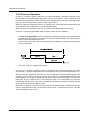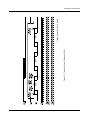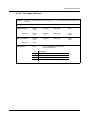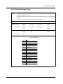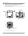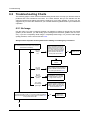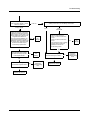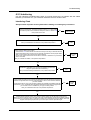
1
Draft
Basler A202k
USER’S MANUAL
Document Number: DA0440
Version: 08 Language: 000 (English)
Release Date: 29 June 2007
For customers in the U.S.A.
This equipment has been tested and found to comply with the limits for a Class A digital device,
pursuant to Part 15 of the FCC Rules. These limits are designed to provide reasonable protection against harmful interference when the equipment is operated in a commercial environment. This equipment generates, uses, and can radiate radio frequency energy and, if not
installed and used in accordance with the instruction manual, may cause harmful interference
to radio communications. Operation of this equipment in a residential area is likely to cause
harmful interference in which case the user will be required to correct the interference at his
own expense.
You are cautioned that any changes or modifications not expressly approved in this manual
could void your authority to operate this equipment.
The shielded interface cable recommended in this manual must be used with this equipment
in order to comply with the limits for a computing device pursuant to Subpart J of Part 15 of
FCC Rules.
For customers in Canada
This apparatus complies with the Class A limits for radio noise emissions set out in Radio Interference Regulations.
Pour utilisateurs au Canada
Cet appareil est conforme aux normes Classe A pour bruits radioélectriques, spécifiées dans
le Règlement sur le brouillage radioélectrique.
Life Support Applications
These products are not designed for use in life support appliances, devices, or systems where
malfunction of these products can reasonably be expected to result in personal injury. Basler
customers using or selling these products for use in such applications do so at their own risk
and agree to fully indemnify Basler for any damages resulting from such improper use or sale.
Warranty Note
Do not open the housing of the camera. The warranty becomes void if the housing is opened.
All material in this publication is subject to change without notice and is copyright
Basler Vision Technologies.
Contacting Basler Support Worldwide
Europe:
Basler AG
Ander Strusbek 60 - 62
22926 Ahrensburg
Germany
Tel.: +49-4102-463-500
Fax.: +49-4102-463-599
[email protected]
Americas:
Basler, Inc.
855 Springdale Drive, Suite 160
Exton, PA 19341
U.S.A.
Tel.: +1-877-934-8472
Fax.: +1-877-934-7608
[email protected]
Asia:
Basler Asia Pte Ltd
8 Boon Lay Way,
#03-03 Tradehub 21
Singapore 609964
Tel.: +65-6425-0472
Fax.: +65-6425-0473
[email protected]
www.basler-vc.com
DRAFT
Contents
Table of Contents
1 Introduction
1.1 Camera Models . . . . . . . . . . . . . . . . . . . . . . . . . . . . . . . . . . . . . . . . . . . . . . . . . . . 1-1
1.2 Performance Specifications . . . . . . . . . . . . . . . . . . . . . . . . . . . . . . . . . . . . . . . . . . 1-2
1.3 Spectral Response . . . . . . . . . . . . . . . . . . . . . . . . . . . . . . . . . . . . . . . . . . . . . . . . . 1-3
1.4 Environmental Requirements . . . . . . . . . . . . . . . . . . . . . . . . . . . . . . . . . . . . . . . . . 1-5
1.4.1 Temperature and Humidity . . . . . . . . . . . . . . . . . . . . . . . . . . . . . . . . . . . . . . 1-5
1.4.2 Ventilation . . . . . . . . . . . . . . . . . . . . . . . . . . . . . . . . . . . . . . . . . . . . . . . . . . . 1-5
1.5 Precautions . . . . . . . . . . . . . . . . . . . . . . . . . . . . . . . . . . . . . . . . . . . . . . . . . . . . . . . 1-5
2 Camera Interface
2.1 Connections . . . . . . . . . . . . . . . . . . . . . . . . . . . . . . . . . . . . . . . . . . . . . . . . . . . . . . 2-1
2.1.1 General Description. . . . . . . . . . . . . . . . . . . . . . . . . . . . . . . . . . . . . . . . . . . . 2-1
2.1.2 Pin Assignments . . . . . . . . . . . . . . . . . . . . . . . . . . . . . . . . . . . . . . . . . . . . . . 2-2
2.1.3 Connector Types . . . . . . . . . . . . . . . . . . . . . . . . . . . . . . . . . . . . . . . . . . . . . . 2-3
2.2 Cable Information . . . . . . . . . . . . . . . . . . . . . . . . . . . . . . . . . . . . . . . . . . . . . . . . . . 2-4
2.2.1 Camera Link Cable . . . . . . . . . . . . . . . . . . . . . . . . . . . . . . . . . . . . . . . . . . . . 2-4
2.2.2 Power Cable . . . . . . . . . . . . . . . . . . . . . . . . . . . . . . . . . . . . . . . . . . . . . . . . . 2-4
2.3 Camera Link Implementation in the A202k . . . . . . . . . . . . . . . . . . . . . . . . . . . . . . . 2-4
2.4 Input Signals . . . . . . . . . . . . . . . . . . . . . . . . . . . . . . . . . . . . . . . . . . . . . . . . . . . . . . 2-6
2.4.1 ExSync: Controls Frame Readout and Exposure Time. . . . . . . . . . . . . . . . . 2-6
2.5 Output Signals . . . . . . . . . . . . . . . . . . . . . . . . . . . . . . . . . . . . . . . . . . . . . . . . . . . . 2-7
2.5.1 Pixel Clock. . . . . . . . . . . . . . . . . . . . . . . . . . . . . . . . . . . . . . . . . . . . . . . . . . . 2-7
2.5.2 Frame Valid Bit . . . . . . . . . . . . . . . . . . . . . . . . . . . . . . . . . . . . . . . . . . . . . . . 2-7
2.5.3 Line Valid Bit . . . . . . . . . . . . . . . . . . . . . . . . . . . . . . . . . . . . . . . . . . . . . . . . . 2-7
2.5.4 Video Data. . . . . . . . . . . . . . . . . . . . . . . . . . . . . . . . . . . . . . . . . . . . . . . . . . . 2-8
2.5.4.1 Bit Assignments . . . . . . . . . . . . . . . . . . . . . . . . . . . . . . . . . . . . . . . 2-8
2.5.4.2 Video Data Output Modes . . . . . . . . . . . . . . . . . . . . . . . . . . . . . . . . 2-9
2.5.5 Integrate Enabled Signal . . . . . . . . . . . . . . . . . . . . . . . . . . . . . . . . . . . . . . . 2-13
2.6 RS-644 Serial Communication . . . . . . . . . . . . . . . . . . . . . . . . . . . . . . . . . . . . . . . 2-14
2.6.1 Making the Serial Connection . . . . . . . . . . . . . . . . . . . . . . . . . . . . . . . . . . . 2-14
2.7 Converting Camera Link Output to RS-644 with a k-BIC . . . . . . . . . . . . . . . . . . . 2-15
2.8 DC Power . . . . . . . . . . . . . . . . . . . . . . . . . . . . . . . . . . . . . . . . . . . . . . . . . . . . . . . 2-15
2.9 Status LED . . . . . . . . . . . . . . . . . . . . . . . . . . . . . . . . . . . . . . . . . . . . . . . . . . . . . . 2-16
BASLER A202k
I
Contents
DRAFT
3 Basic Operation and Features
3.1 Functional Description . . . . . . . . . . . . . . . . . . . . . . . . . . . . . . . . . . . . . . . . . . . . . . 3-1
3.2 Exposure Time Control . . . . . . . . . . . . . . . . . . . . . . . . . . . . . . . . . . . . . . . . . . . . . . 3-3
3.2.1 ExSync Controlled Operation . . . . . . . . . . . . . . . . . . . . . . . . . . . . . . . . . . . . 3-3
3.2.1.1 Basics of ExSync Controlled Operation . . . . . . . . . . . . . . . . . . . . . 3-3
3.2.1.2 Recommendations for Controlling Exposure
in ExSync Level-Controlled Mode . . . . . . . . . . . . . . . . . . . . . . . . . . 3-4
3.2.1.3 Recommendations for Controlling Exposure
in ExSync Programmable Mode . . . . . . . . . . . . . . . . . . . . . . . . . . . 3-7
3.2.2 Free-run Operation . . . . . . . . . . . . . . . . . . . . . . . . . . . . . . . . . . . . . . . . . . . 3-10
3.2.2.1 Recommendations for Controlling Exposure
in Free-run Programmable Mode . . . . . . . . . . . . . . . . . . . . . . . . . 3-11
3.3 Video Data Output Modes . . . . . . . . . . . . . . . . . . . . . . . . . . . . . . . . . . . . . . . . . . 3-12
3.4 Integrate Enabled Signal . . . . . . . . . . . . . . . . . . . . . . . . . . . . . . . . . . . . . . . . . . . 3-12
3.5 Gain and Offset . . . . . . . . . . . . . . . . . . . . . . . . . . . . . . . . . . . . . . . . . . . . . . . . . . 3-13
3.5.1 Setting the Gain. . . . . . . . . . . . . . . . . . . . . . . . . . . . . . . . . . . . . . . . . . . . . . 3-14
3.5.2 Balancing the Left Side and Right Side Gain . . . . . . . . . . . . . . . . . . . . . . . 3-15
3.5.2.1 Balancing Gain Settings When Using Binary Commands . . . . . . . 3-16
3.5.3 Setting the Offset. . . . . . . . . . . . . . . . . . . . . . . . . . . . . . . . . . . . . . . . . . . . . 3-18
3.5.4 Balancing the Left Side and Right Side Offset . . . . . . . . . . . . . . . . . . . . . . 3-19
3.5.4.1 Balancing Offset Settings When Using Binary Commands . . . . . . 3-19
3.5.5 Balancing Gain and Offset . . . . . . . . . . . . . . . . . . . . . . . . . . . . . . . . . . . . . 3-21
3.6 Digital Shift . . . . . . . . . . . . . . . . . . . . . . . . . . . . . . . . . . . . . . . . . . . . . . . . . . . . . . 3-22
3.6.1 Digital Shift in 10 bit Output Mode . . . . . . . . . . . . . . . . . . . . . . . . . . . . . . . . 3-22
3.6.2 Digital Shift in 8 bit Output Modes . . . . . . . . . . . . . . . . . . . . . . . . . . . . . . . . 3-23
3.6.3 Precautions When Using Digital Shift . . . . . . . . . . . . . . . . . . . . . . . . . . . . . 3-25
3.7 Area of Interest (AOI) . . . . . . . . . . . . . . . . . . . . . . . . . . . . . . . . . . . . . . . . . . . . . . 3-26
3.7.1 AOI Setup Guidelines . . . . . . . . . . . . . . . . . . . . . . . . . . . . . . . . . . . . . . . . . 3-27
3.7.2 Changes to the Maximum Frame Rate with Area of Interest. . . . . . . . . . . . 3-27
3.7.3 Changes to the Pixel Timing and Output with AOI . . . . . . . . . . . . . . . . . . . 3-28
3.8 Binning . . . . . . . . . . . . . . . . . . . . . . . . . . . . . . . . . . . . . . . . . . . . . . . . . . . . . . . . . 3-30
3.8.1 Changes to the Maximum Frame Rate with Binning . . . . . . . . . . . . . . . . . . 3-31
3.9 Mirror Image . . . . . . . . . . . . . . . . . . . . . . . . . . . . . . . . . . . . . . . . . . . . . . . . . . . . . 3-31
3.10 Color Creation in the A202kc . . . . . . . . . . . . . . . . . . . . . . . . . . . . . . . . . . . . . . . 3-32
3.11 Test Images . . . . . . . . . . . . . . . . . . . . . . . . . . . . . . . . . . . . . . . . . . . . . . . . . . . . 3-33
3.11.1 Test Image One. . . . . . . . . . . . . . . . . . . . . . . . . . . . . . . . . . . . . . . . . . . . . 3-33
3.11.2 Test Image Two. . . . . . . . . . . . . . . . . . . . . . . . . . . . . . . . . . . . . . . . . . . . . 3-34
3.11.3 Test Image Three . . . . . . . . . . . . . . . . . . . . . . . . . . . . . . . . . . . . . . . . . . . 3-34
3.12 Configuration Sets . . . . . . . . . . . . . . . . . . . . . . . . . . . . . . . . . . . . . . . . . . . . . . . 3-35
3.13 Camera Temperature . . . . . . . . . . . . . . . . . . . . . . . . . . . . . . . . . . . . . . . . . . . . . 3-36
3.14 Camera Status . . . . . . . . . . . . . . . . . . . . . . . . . . . . . . . . . . . . . . . . . . . . . . . . . . 3-36
II
BASLER A202k
DRAFT
Contents
4 Configuring the Camera
4.1 Configuring the Camera with the Camera Configuration Tool Plus (CCT+) . . . . . 4-2
4.1.1 Opening the Configuration Tool. . . . . . . . . . . . . . . . . . . . . . . . . . . . . . . . . . . 4-2
4.1.2 Closing the Configuration Tool . . . . . . . . . . . . . . . . . . . . . . . . . . . . . . . . . . . 4-2
4.1.3 Configuration Tool Basics . . . . . . . . . . . . . . . . . . . . . . . . . . . . . . . . . . . . . . . 4-3
4.1.4 Configuration Tool Help. . . . . . . . . . . . . . . . . . . . . . . . . . . . . . . . . . . . . . . . . 4-4
4.2 Configuring the Camera with Binary Programming Commands . . . . . . . . . . . . . . . 4-5
4.2.1 Command Frame and Response Format . . . . . . . . . . . . . . . . . . . . . . . . . . . 4-6
4.2.2 Error Checking. . . . . . . . . . . . . . . . . . . . . . . . . . . . . . . . . . . . . . . . . . . . . . . . 4-8
4.2.2.1 ACK/NAK . . . . . . . . . . . . . . . . . . . . . . . . . . . . . . . . . . . . . . . . . . . . 4-8
4.2.2.2 Time-outs . . . . . . . . . . . . . . . . . . . . . . . . . . . . . . . . . . . . . . . . . . . . 4-8
4.2.2.3 Read Command . . . . . . . . . . . . . . . . . . . . . . . . . . . . . . . . . . . . . . . 4-8
4.2.2.4 Write Command . . . . . . . . . . . . . . . . . . . . . . . . . . . . . . . . . . . . . . . 4-8
4.2.3 Example Commands . . . . . . . . . . . . . . . . . . . . . . . . . . . . . . . . . . . . . . . . . . 4-9
4.2.3.1 Read command . . . . . . . . . . . . . . . . . . . . . . . . . . . . . . . . . . . . . . . . 4-9
4.2.3.2 Write Command . . . . . . . . . . . . . . . . . . . . . . . . . . . . . . . . . . . . . . . 4-9
4.2.3.3 Calculating the Block Check Character . . . . . . . . . . . . . . . . . . . . . 4-10
4.2.4 Commands for Setting Camera Parameters . . . . . . . . . . . . . . . . . . . . . . . . 4-11
4.2.4.1 Video Data Output Mode . . . . . . . . . . . . . . . . . . . . . . . . . . . . . . . . 4-11
4.2.4.2 Exposure Time Control Mode . . . . . . . . . . . . . . . . . . . . . . . . . . . . 4-12
4.2.4.3 Timer 1 . . . . . . . . . . . . . . . . . . . . . . . . . . . . . . . . . . . . . . . . . . . . . 4-13
4.2.4.4 Timer 2 . . . . . . . . . . . . . . . . . . . . . . . . . . . . . . . . . . . . . . . . . . . . . 4-13
4.2.4.5 Digital Shift . . . . . . . . . . . . . . . . . . . . . . . . . . . . . . . . . . . . . . . . . . 4-14
4.2.4.6 Area of Interest Starting Column . . . . . . . . . . . . . . . . . . . . . . . . . . 4-15
4.2.4.7 Area of Interest Width in Columns . . . . . . . . . . . . . . . . . . . . . . . . . 4-15
4.2.4.8 Area of Interest Starting Line . . . . . . . . . . . . . . . . . . . . . . . . . . . . 4-16
4.2.4.9 Area of Interest Height in Lines . . . . . . . . . . . . . . . . . . . . . . . . . . . 4-16
4.2.4.10 Left Side Gain . . . . . . . . . . . . . . . . . . . . . . . . . . . . . . . . . . . . . . . 4-17
4.2.4.11 Left Side Offset . . . . . . . . . . . . . . . . . . . . . . . . . . . . . . . . . . . . . . 4-17
4.2.4.12 Right Side Gain . . . . . . . . . . . . . . . . . . . . . . . . . . . . . . . . . . . . . . 4-18
4.2.4.13 Right Side Offset . . . . . . . . . . . . . . . . . . . . . . . . . . . . . . . . . . . . . 4-18
4.2.4.14 Horizontal Binning . . . . . . . . . . . . . . . . . . . . . . . . . . . . . . . . . . . . 4-19
4.2.4.15 Vertical Binning . . . . . . . . . . . . . . . . . . . . . . . . . . . . . . . . . . . . . . 4-19
4.2.4.16 Mirror Image . . . . . . . . . . . . . . . . . . . . . . . . . . . . . . . . . . . . . . . . 4-20
4.2.4.17 Test Image Command . . . . . . . . . . . . . . . . . . . . . . . . . . . . . . . . . 4-21
4.2.5 Query Commands . . . . . . . . . . . . . . . . . . . . . . . . . . . . . . . . . . . . . . . . . . . . 4-22
4.2.5.1 Read Vendor Information . . . . . . . . . . . . . . . . . . . . . . . . . . . . . . . 4-22
4.2.5.2 Read Model Information . . . . . . . . . . . . . . . . . . . . . . . . . . . . . . . . 4-22
4.2.5.3 Read Product ID . . . . . . . . . . . . . . . . . . . . . . . . . . . . . . . . . . . . . . 4-22
4.2.5.4 Read Serial Number . . . . . . . . . . . . . . . . . . . . . . . . . . . . . . . . . . . 4-23
4.2.5.5 Read Camera Version . . . . . . . . . . . . . . . . . . . . . . . . . . . . . . . . . . 4-23
4.2.5.6 Read EEPROM Firmware Version . . . . . . . . . . . . . . . . . . . . . . . . 4-23
4.2.5.7 Read Microcontroller Firmware Version . . . . . . . . . . . . . . . . . . . . 4-24
BASLER A202k
III
DRAFT
Contents
4.2.5.8 Read FPGA Firmware Version . . . . . . . . . . . . . . . . . . . . . . . . . . . 4-24
4.2.5.9 Read Camera Temperature . . . . . . . . . . . . . . . . . . . . . . . . . . . . . 4-25
4.2.5.10 Reference Values . . . . . . . . . . . . . . . . . . . . . . . . . . . . . . . . . . . . 4-26
4.2.6 Commands for Manipulating Configuration Sets . . . . . . . . . . . . . . . . . . . . . 4-27
4.2.6.1 Copy the Factory Set or a User Set into the Work Set . . . . . . . . . 4-27
4.2.6.2 Copy Work Set into a User Set . . . . . . . . . . . . . . . . . . . . . . . . . . . 4-28
4.2.6.3 Select the Startup Pointer . . . . . . . . . . . . . . . . . . . . . . . . . . . . . . . 4-29
4.2.7 Camera Status Command . . . . . . . . . . . . . . . . . . . . . . . . . . . . . . . . . . . . . . 4-30
4.2.8 Bitrate Command. . . . . . . . . . . . . . . . . . . . . . . . . . . . . . . . . . . . . . . . . . . . . 4-31
4.2.9 Camera Reset Command . . . . . . . . . . . . . . . . . . . . . . . . . . . . . . . . . . . . . . 4-32
5 Mechanical Considerations
5.1 Camera Dimensions and Mounting Facilities . . . . . . . . . . . . . . . . . . . . . . . . . . . . . 5-2
5.2 Sensor Positioning Accuracy . . . . . . . . . . . . . . . . . . . . . . . . . . . . . . . . . . . . . . . . . 5-3
5.3 C-Mount Adapter Dimensions . . . . . . . . . . . . . . . . . . . . . . . . . . . . . . . . . . . . . . . . 5-4
5.4 F-Mount Adapter Dimensions . . . . . . . . . . . . . . . . . . . . . . . . . . . . . . . . . . . . . . . . . 5-4
5.5 Maximum Lens Thread Length on C-mount Equipped Cameras . . . . . . . . . . . . . . 5-5
6 Troubleshooting
6.1 Fault Finding Using the Camera LED . . . . . . . . . . . . . . . . . . . . . . . . . . . . . . . . . . . 6-1
6.2 Troubleshooting Charts . . . . . . . . . . . . . . . . . . . . . . . . . . . . . . . . . . . . . . . . . . . . . 6-2
6.2.1 No Image . . . . . . . . . . . . . . . . . . . . . . . . . . . . . . . . . . . . . . . . . . . . . . . . . . . . 6-2
6.2.2 Image Quality Problems . . . . . . . . . . . . . . . . . . . . . . . . . . . . . . . . . . . . . . . . 6-4
6.2.3 Interfacing . . . . . . . . . . . . . . . . . . . . . . . . . . . . . . . . . . . . . . . . . . . . . . . . . . . 6-5
6.2.4 RS-644 Serial Communication . . . . . . . . . . . . . . . . . . . . . . . . . . . . . . . . . . . 6-6
6.3 Before Calling Basler Technical Support . . . . . . . . . . . . . . . . . . . . . . . . . . . . . . . . 6-7
Revision History . . . . . . . . . . . . . . . . . . . . . . . . . . . . . . . . . . . . . . . . . . . . . . i
Feedback . . . . . . . . . . . . . . . . . . . . . . . . . . . . . . . . . . . . . . . . . . . . . . . . . . . iii
Index . . . . . . . . . . . . . . . . . . . . . . . . . . . . . . . . . . . . . . . . . . . . . . . . . . . . . . . v
IV
BASLER A202k
DRAFT
Introduction
1 Introduction
The Basler A202k high resolution, progressive scan camera is a versatile camera designed for
industrial use. Superb image sensing features are combined with a robust, high-precision,
machined housing.
Important features are:
• High spatial resolution
• High sensitivity
• Anti-blooming
• Asynchronous full frame shutter via electronic exposure control
• Square sensor cells
• High Signal-to-Noise ratio
• Programmable via an RS-644 serial port
• Area of Interest (AOI) scanning
• Correlated double sampling
• Industrial housing manufactured with high planar, parallel, and angular precision
• Compact size
• Complies with the Camera Link standard
1.1 Camera Models
The camera is available in a monochrome model (the A202k) and a color model (the A202kc).
Throughout the manual, the camera will be called the A202k. Passages that are only valid for a
specific model will be so indicated.
BASLER A202k
1-1
DRAFT
Introduction
1.2 Performance Specifications
Specification
A202k
A202kc
Sensor
Kodak KAI-1020 Interline Transfer Progressive Scan CCD Sensor
Pixels
1004 (H) x 1004 (V)
Pixel Size
7.4 µm x 7.4 µm
Mono or Color
Mono
Color
Spectral Response
See Figure 1-1
See Figure 1-2
Photo Response
Non-uniformity
± 5% (typical)
Dark Signal Non-uniformity
± 1 gray value (typical)
Pixel Clock Speed
40 MHz
(20 MHz when horizontal or full binning is used)
Max. Frame Rate
48 Frames/sec. at full resolution
Video Output Type
Camera Link LVDS
(RS-644 when used with the optional Basler Interface Controller)
Video Output Formats
Dual 8 Bit or Dual 10 Bit
Synchronization
Via external ExSync signal or free-run
Exposure Time Control
Level-controlled, programmable, or free-run
Gain and Offset
Programmable via an RS-644 serial connection on the frame grabber
Connectors
One, 26-pin, female MDR connector
One, 6-pin, Hirose micro-miniature receptacle
Power Requirements
12 VDC (± 10%), max. 5.5 W, < 1% ripple
Lens Adapters
C-mount or F-mount
Housing Size (L x W x H)
without lens adapter:
37.6 mm x 62 mm x 62 mm
with C-mount adapter:
40.1 mm x 62 mm x 62 mm
with F-mount adapter:
69.1 mm x 62 mm x 62 mm
without lens adapter:
~ 180 g
with C-mount adapter:
~ 220 g
with F-mount adapter:
~ 290 g
Weight
Conformity
CE, FCC
Table 1-1: A202k Performance Specifications
1-2
BASLER A202k
DRAFT
Introduction
1.3 Spectral Response
The spectral response for the A202k monochrome camera is shown in Figure 1-1.
Figure 1-1: A202k Mono Spectral Response
BASLER A202k
1-3
DRAFT
Introduction
The spectral response for the A202kc color camera is shown in Figure 1-2.
Figure 1-2: A202kc ColorSpectral Response
L
The spectral response curve excludes lens characteristics and light source
characteristics.
To obtain best performance regarding the camera’s blooming, smearing and dark
signal non-uniformity characteristics, use of a dielectric IR cut-off filter is
recommended. The filter should transmit in a range of 400 nm to 700...720 nm, and
it should cut off from 700...720 nm to 1100 nm.
A suitable filter is included in the C-mount adapter.
The F-mount adapter does not include the filter. A suitable filter type is the B+W486,
for example.
Caution!
A202kc cameras shipped with a C-mount lens adapter are equipped with an IR
cut filter as standard equipment. The filter is mounted in the lens adapter. The
location of the filter limits the thread length of the lens that can be used on the
camera. The thread length on your lens must be less than 7.5 mm. If a lens with
a longer thread length is used, the camera will be damaged and will no longer
operate. See Section 5.5 for more details.
Cameras without an IR cut filter in the C-mount lens adapter are available on request.
1-4
BASLER A202k
DRAFT
Introduction
1.4 Environmental Requirements
1.4.1 Temperature and Humidity
Housing temperature during operation:
0 °C ... + 50 °C (+ 32 °F ... + 122 °F)
Humidity during operation:
20 % ... 80 %, relative, non-condensing
Housing temperature during storage:
-20 °C ... + 80 °C (- 4 °F ... + 176 °F)
Humidity during storage:
5 % ... 95 %, relative, non-condensing
1.4.2 Ventilation
Allow sufficient air circulation around the camera to prevent internal heat build-up in your system
and to keep the camera housing temperature during operation below 50 °C. Provide additional
cooling such as fans or heat sinks if necessary.
Warning!
Without sufficient cooling, the camera can get hot enough during operation to cause burning when touched.
1.5 Precautions
To ensure that your warranty remains in force:
Powerrr
Caution!
Be sure that all power to your system is switched off before you make or break
connections to the camera. Making or breaking connections when power is on
can result in damage to the camera.
Caution!
The camera has no overvoltage protection. An input voltage higher than
14 VDC will damage the camera.
Caution!
Do not reverse the polarity of the input power to the camera. Reversing the
polarity of the input power can severely damage the camera and leave it nonoperational.
BASLER A202k
1-5
Introduction
DRAFT
Read the manual
Read the manual carefully before using the camera.
Keep foreign matter outside of the camera
Do not open the casing. Touching internal components may damage them.
Be careful not to allow liquid, flammable, or metallic material inside the camera housing. If
operated with any foreign matter inside, the camera may fail or cause a fire.
Electromagnetic Fields
Do not operate the camera in the vicinity of strong electromagnetic fields. Avoid electrostatic
charging.
Transporting
Only transport the camera in its original packaging. Do not discard the packaging.
Cleaning
Avoid cleaning the surface of the CCD sensor if possible. If you must clean it, use a soft, lint free
cloth dampened with a small quantity of high quality window cleaner. Do not use methylated
alcohol.
Because electrostatic discharge can damage the CCD sensor, you must use a cloth that will not
generate static during cleaning (cotton is a good choice).
To clean the surface of the camera housing, use a soft, dry cloth. To remove severe stains, use a
soft cloth dampened with a small quantity of neutral detergent, then wipe dry.
Do not use volatile solvents such as benzine and thinners; they can damage the surface finish.
1-6
BASLER A202k
DRAFT
Camera Interface
2 Camera Interface
2.1 Connections
2.1.1 General Description
The A202k is interfaced to external circuitry via two connectors located on the back of the camera:
• a 26 pin, .050” Mini D Ribbon (MDR) female connector used to transmit video data, control
signals, and configuration commands.
• a 6 pin, micro-miniature, push-pull receptacle used to provide power to the camera.
A status LED located on the back of the camera is used to indicate power present and signal
integrity. Figure 2-1 shows the connectors and the LED.
Figure 2-1: A202k Connectors and LED
BASLER A202k
2-1
DRAFT
Camera Interface
2.1.2 Pin Assignments
26-Pin MDR Connector
The pin assignments for the 26 pin, MDR connector used to transmit video data, control signals,
and configuration commands are shown in Table 2-1.
Pin
Number
Signal
Name
Direction
Level
Function
15
Tx X0+
Output
Data from Camera Link Transmitter
2
Tx X0-
Camera Link
LVDS
16
Tx X1+
Output
Data from Camera Link Transmitter
3
Tx X1-
Camera Link
LVDS
17
Tx X2+
Output
Data from Camera Link Transmitter
4
Tx X2-
Camera Link
LVDS
19
Tx X3+
Output
Data from Camera Link Transmitter
6
Tx X3-
Camera Link
LVDS
18
Tx Clk+
Output
Clock from Camera Link Transmitter
5
Tx Clk-
Camera Link
LVDS
12
CC4+
Input
Reserved for Future Use
25
CC4-
RS-644
LVDS
24
CC3+
Output
Integrate Enabled
11
CC3-
RS-644
LVDS
10
CC2+
Input
Reserved for Future Use
23
CC2-
RS-644
LVDS
22
CC1+
Input
External Trigger
9
CC1-
RS-644
LVDS
21
SerTFG+
Output
Serial Communication Data Transmit
8
SerTFG-
RS-644
LVDS
7
SerTC+
Input
Serial Communication Data Receive
20
SerTC-
RS-644
LVDS
1, 13,
DC Gnd
Input
Ground
DC Ground
14, 26 [1]
[1]
Pins 1, 13, 14, and 26 are all tied together inside of the camera.
Table 2-1: A202k Pin Assignments for the 26-pin MDR Connector
L
2-2
The camera housing is not grounded and is electrically isolated from the circuit boards inside of the camera.
BASLER A202k
DRAFT
Camera Interface
6-Pin Micro-miniature Receptacle
The pin assignments for the 6 pin, micro-miniature receptacle used to supply power to the camera
are shown in Table 2-2.
Pin
Number
Signal
Name
Direction
Level
Function
1, 2 [1]
12 V In
Input
+12 VDC
Camera Power Input
3
Not Connected
4
Not Connected
5, 6 [2]
DC Gnd
Input
Ground
[1]
Pins 1 and 2 are tied together inside of the camera.
[2]
Pins 5 and 6 are tied together inside of the camera.
DC Ground
Table 2-2: A202k Pin Assignments for the 6-pin Micro-miniature Receptacle
Figure 2-2: A202k Pin Numbering
2.1.3 Connector Types
The 26 pin connector on the camera is a female .050” MDR connector as called for in the Camera
Link Specification.
The 6 pin connector on the camera is a Hirose micro-miniature locking receptacle (part # HR10A7R-6PB) or the equivalent. The recommended mating connector is the Hirose micro-miniature
locking plug (part # HR10A-7P-6S). A Hirose locking plug will be shipped with each camera. This
plug should be used to terminate the cable on the power supply for the camera. For proper EMI
protection, the power supply cable attached to this plug must be a twin-cored, shielded cable.
Also, the housing of the Hirose plug must be connected to the cable shield and the cable shield
must be connected to earth ground at the power supply.
BASLER A202k
2-3
DRAFT
Camera Interface
2.2 Cable Information
2.2.1 Camera Link Cable
A Camera Link compatible MDR cable assembly is available from Basler as a stock item (part #
1000013041 for a 3 meter cable and part # 1000013042 for a 5 meter cable). Alternatively, you
can use the cable assembly manufactured by 3M (part # 14X26-SZLB-XXX-0LC).
The maximum allowed length for the MDR cable used with an A202k is 10 meters.
L
In order to access the Integrate Enabled signal, you must use the Basler stock cable
(see Sect. 2.5.5).
2.2.2 Power Cable
A Hirose, 6-pin locking plug will be shipped with each camera. This plug should be used to connect
the power supply cable to the camera.
For proper EMI protection, the power supply cable attached to this plug must be a twin-cored,
shielded cable. Also, the housing of the Hirose plug must be connected to the cable shield and
the cable shield must be connected to earth ground at the power supply.
Power requirements are given in Section 2.8.
2.3 Camera Link Implementation in the A202k
The A202k uses a National Semiconductor DS90CR287 as a Camera Link transmitter. For a
Camera Link receiver, we recommend that you use the National Semiconductor DS90CR288, the
National Semiconductor DS90CR288A or an equivalent. Detailed data sheets for these
components are available at the National Semiconductor web site (www.national.com). The data
sheets contain all of the information that you need to implement Camera Link, including
application notes.
L
Note that the timing used for sampling the data at the Camera Link receiver in the
frame grabber varies from device to device. On some receivers, TTL data must be
sampled on the rising edge of the receive clock, and on others, it must be sampled
on the falling edge. Also, some devices are available which allow you to select either
rising edge or falling edge sampling. Please consult the data sheet for the receiver
that you are using for specific timing information.
The A202k uses a National Semiconductor DS90LV048A differential line receiver to receive the
RS-644 camera control input signals and the serial communication input signal defined in the
Camera Link specification. A DS90LV047A differential line transmitter is used to transmit the serial
communication output signal defined in the specification. Detailed spec sheets for these devices
are available at the National Semiconductor web site (www.national.com).
The schematic in Figure 2-3 shows the interface for A202k and a typical implementation for the
frame grabber interface.
2-4
BASLER A202k
DRAFT
Camera Interface
Figure 2-3: Camera / Frame Grabber Interface
BASLER A202k
2-5
DRAFT
Camera Interface
2.4 Input Signals
The only control signal that can be input into the A202k is an external sync (ExSync) signal.
ExSync is an RS-644 LVDS signal as specified in the Camera Link standard. Section 2.4.1
describes the function of the ExSync signal.
2.4.1 ExSync: Controls Frame Readout and Exposure Time
The ExSync input signal is used to control exposure time and frame read out. When the camera
is operating with an ExSync signal, two exposure time control modes are available: levelcontrolled and programmable. For more detailed information on the two modes, see Section 3.2.
ExSync can be a periodic or non-periodic function. The frequency of the ExSync signal
determines the camera’s frame rate:
1
Maximum frame rate = ---------------------------------------------------------------------------------Minimum ExSync signal period
Note that ExSync is edge sensitive and therefore must toggle.
Minimum high time for the ExSync signal is 4 µs.
The ExSync signal is typically supplied to the camera by a frame grabber board. You should refer
to the manual supplied with your frame grabber to determine how to set up the ExSync signal that
is being supplied to the camera.
2-6
BASLER A202k
DRAFT
Camera Interface
2.5 Output Signals
The camera’s output signals include a pixel clock, video data, and video data qualifiers such as
frame valid and line valid. An integrate enabled output signal is also available. Sections 2.5.1
through 2.5.5 describe the output signals.
2.5.1 Pixel Clock
As shown in Figure 2-3 and in Table 2-3, the pixel clock is assigned to the TxClkIn (transmit clock)
pin of the Camera Link transmitter. The pixel clock is used to time the sampling and transmission
of pixel data as shown in Figures 2-4 and 2-5. The transmitter used in A202k cameras requires
pixel data to be sampled and transmitted on the falling edge of the clock.
The frequency of the pixel clock is normally 40 MHz. However, when horizontal or full binning is
enabled, the pixel clock is 20 MHz.
L
Note that the timing used for sampling the data at the Camera Link receiver in the
frame grabber varies from device to device. On some receivers, data must be sampled on the rising edge of the pixel clock (receive clock), and on others, it must be
sampled on the falling edge. Also, some devices are available which allow you to
select either rising edge or falling edge sampling. Please consult the data sheet for
the receiver that you are using for specific timing information.
2.5.2 Frame Valid Bit
As shown in Figures 2-4 and 2-5, the frame valid bit indicates that a valid frame is being
transmitted.
2.5.3 Line Valid Bit
As shown in Figures 2-4 and 2-5, the line valid bit indicates that a valid line is being transmitted.
Pixel data is only valid when the frame valid bit and the line valid bit are both high.
BASLER A202k
2-7
DRAFT
Camera Interface
2.5.4 Video Data
2.5.4.1 Bit Assignments
Table 2-3 lists the assignment of pixel data bits to the input ports on the transmitter in the camera
and the corresponding output pins on the receiver in the frame grabber. These bit assignments
comply with the Camera Link standard. As shown in the table, the bit assignments for pixel data
vary depending on the output mode setting of the camera. The available output modes are
explained in more detail in Section 2.5.4.2.
Table 2-3 also shows the assignment for the frame valid bit, the line valid bit and the pixel clock.
These assignments are constant for all output modes.
Port
Camera
Frame
Grabber
Dual 10 Bit
Output Mode
Dual 8 Bit
Output Mode
Port A0
TxIN0
RxOUT0
Odd Pixel Bit 0
Odd Pixel Bit 0
Port A1
TxIN1
RxOUT1
Odd Pixel Bit 1
Odd Pixel Bit 1
Port A2
TxIN2
RxOUT2
Odd Pixel Bit 2
Odd Pixel Bit 2
Port A3
TxIN3
RxOUT3
Odd Pixel Bit 3
Odd Pixel Bit 3
Port A4
TxIN4
RxOUT4
Odd Pixel Bit 4
Odd Pixel Bit 4
Port A5
TxIN6
RxOUT6
Odd Pixel Bit 5
Odd Pixel Bit 5
Port A6
TxIN27
RxOUT27
Odd Pixel Bit 6
Odd Pixel Bit 6
Port A7
TxIN5
RxOUT5
Odd Pixel Bit 7
Odd Pixel Bit 7 (MSB)
Port B0
TxIN7
RxOUT7
Odd Pixel Bit 8
Even Pixel Bit 0
Port B1
TxIN8
RxOUT8
Odd Pixel Bit 9 (MSB)
Even Pixel Bit 1
Port B2
TxIN9
RxOUT9
Not Used
Even Pixel Bit 2
Port B3
TxIN12
RxOUT12
Not Used
Even Pixel Bit 3
Port B4
TxIN13
RxOUT13
Even Pixel Bit 8
Even Pixel Bit 4
Port B5
TxIN14
RxOUT14
Even Pixel Bit 9 (MSB)
Even Pixel Bit 5
Port B6
TxIN10
RxOUT10
Not Used
Even Pixel Bit 6
Port B7
TxIN11
RxOUT11
Not Used
Even Pixel Bit 7 (MSB)
Port C0
TxIN15
RxOUT15
Even Pixel Bit 0
Not Used
Port C1
TxIN18
RxOUT18
Even Pixel Bit 1
Not Used
Port C2
TxIN19
RxOUT19
Even Pixel Bit 2
Not Used
Port C3
TxIN20
RxOUT20
Even Pixel Bit 3
Not Used
Port C4
TxIN21
RxOUT21
Even Pixel Bit 4
Not Used
Port C5
TxIN22
RxOUT22
Even Pixel Bit 5
Not Used
Port C6
TxIN16
RxOUT16
Even Pixel Bit 6
Not Used
Port C7
TxIN17
RxOUT17
Even Pixel Bit 7
Not Used
LVAL
TxIN24
RxOUT24
Line Valid
Line Valid
FVAL
TxIN25
RxOUT25
Frame Valid
Frame Valid
Not Used
TxIN26
RxOUT26
Not Used
Not Used
Not Used
TxIN23
RxOUT23
Not Used
Not Used
PClk
TxCLKIn
RxCLKOut
Pixel Clock
Pixel Clock
Table 2-3: Bit Assignments
2-8
BASLER A202k
DRAFT
Camera Interface
2.5.4.2 Video Data Output Modes
The A202k can output pixel data in either a Dual 10 Bit, or a Dual 8 Bit output mode. These modes
are described in detail below.
Operation in Dual 10 Bit or Dual 8 Bit Output Mode
In Dual 10 Bit mode, the pixel clock operates at 40 MHz. On each clock cycle, the camera
transmits data for two pixels at 10 bit depth, a frame valid bit, and a line valid bit. The assignment
of the bits is shown in Table 2-3.
The pixel clock is used to time data sampling and transmission. As shown in Figures 2-4 and 2-5,
the camera samples and transmits data on each falling edge of the pixel clock.
The frame valid bit indicates that a valid frame is being transmitted.
The line valid bit indicates that a valid line is being transmitted. Pixel data is only valid when the
frame valid bit and the line valid bit are both high.
Operation in Dual 8 Bit mode is similar to Dual 10 Bit mode except that the two least significant
bits output from each ADC are dropped and only 8 bits of data per pixel is transmitted.
L
The data sequence outlined below, along with Figures 2-4 and 2-5, describe what is
happening at the inputs to the Camera Link transmitter in the camera.
Note that the timing used for sampling the data at the Camera Link receiver in the
frame grabber varies from device to device. On some receivers, data must be sampled on the rising edge of the pixel clock (receive clock), and on others, it must be
sampled on the falling edge. Also, some devices are available which allow you to
select either rising edge or falling edge sampling. Please consult the data sheet for
the receiver that you are using for specific timing information.
Video Data Sequence1
When the camera is not transmitting valid data, the frame valid and line valid bits sent on each
cycle of the pixel clock will be low. Once the camera has completed frame acquisition, it will begin
to send valid data:
• On the pixel clock cycle where frame data transmission begins, the frame valid bit will
become high.
• On the pixel clock cycle where data transmission for line one begins, the line valid bit will
become high. Ten of the bits transmitted during this clock cycle will contain the data for pixel
number one in line one and ten of the bits will contain data for pixel number two in line one.
• On the next cycle of the pixel clock, the line valid bit will be high. Ten of the bits transmitted
during this clock cycle will contain the data for pixel number three in line one and ten of the
bits will contain data for pixel number four in line one.
• On the next cycle of the pixel clock, the line valid bit will be high. Ten of the bits transmitted
during this clock cycle will contain the data for pixel number five in line one and ten of the bits
will contain data for pixel number six in line one.
• This pattern will continue until all of the pixel data for line one has been transmitted.
____________________
1
The data sequence assumes that the camera is operating in 10 bit mode. If the camera is
operating in 8 bit mode, only 8 bits of data per pixel will be transmitted.
BASLER A202k
2-9
Camera Interface
DRAFT
• After all of the pixels in line one have been transmitted, the line valid bit will become low indicating that valid data for line one is no longer being transmitted.
• On the pixel clock cycle where data transmission for line two begins, the line valid bit will
become high. Ten of the bits transmitted during this clock cycle will contain the data for pixel
number one in line two and ten of the bits will contain data for pixel number two in line two.
• On the next cycle of the pixel clock, the line valid bit will be high. Ten of the bits transmitted
during this clock cycle will contain the data for pixel number three in line two and ten of the
bits will contain data for pixel number four in line two.
• On the next cycle of the pixel clock, the line valid bit will be high. Ten of the bits transmitted
during this clock cycle will contain the data for pixel number five in line two and ten of the bits
will contain data for pixel number six in line two.
• This pattern will continue until all of the pixel data for line two has been transmitted.
• After all of the data for the pixels in line two has been transmitted, the line valid bit will
become low indicating that valid data for line two is no longer being transmitted.
• The camera will continue to transmit pixel data for each line as described above until all of
the lines in the frame have been transmitted. After all of the lines have been transmitted, the
frame valid bit will become low indicating that a valid frame is no longer being transmitted.
Figure 2-4 shows the data sequence when the camera is operating in level-controlled exposure
mode. Figure 2-5 shows the data sequence when the camera is operating in programmable
exposure mode.
2-10
BASLER A202k
BASLER A202k
[3]
[2]
[1]
Figure 2-4: Dual 10 Bit or Dual 8 Bit Output Mode with Level Controlled Exposure
TIMING CHARTS ARE NOT DRAWN TO SCALE
The diagram assumes that the area of interest (AOI) feature is not being used. With the AOI feature enabled, the number of lines transferred and the number of pixels
in each line could be smaller.
In the level controlled exposure mode, the fall of ExSync starts exposure. If ExSync falls while a frame is being transferred (while frame valid is high), one line valid
low time immediately following the fall of ExSync will be 15.5 µs.
The line valid low time is 8.0 µs except as described in note 2 below.
DRAFT
Camera Interface
2-11
2-12
[3]
[2]
[1]
Figure 2-5: Dual 10 Bit or Dual 8 Bit Output Mode with Programmable Exposure
TIMING CHARTS ARE NOT DRAWN TO SCALE
The diagram assumes that the area of interest (AOI) feature is not being used. With the AOI feature enabled, the number of lines transferred and the number of pixels
in each line could be smaller.
In the programmable exposure mode, the rise of ExSync starts exposure. If ExSync rises while a frame is being transferred (while frame valid is high), one line valid
low time immediately following the fall of ExSync will be 15.5 µs.
The line valid low time is 8.0 µs except as described in note 2 below.
Camera Interface
DRAFT
BASLER A202k
DRAFT
Camera Interface
2.5.5 Integrate Enabled Signal
An RS-644 LVDS output signal called Integrate Enabled (IntEn) is available on A202k cameras.
The integrate enabled signal indicates that an exposure is taking place. The signal will go high
when each exposure begins and go low when the exposure ends. As shown in the schematic on
page 2-5, the IntEn signal is available on pins 24 and 11 of the A202k.
The integrate enabled signal can not be easily accessed if a standard Camera Link cable is used
between the camera and the frame grabber. However, a Camera Link cable which allows easy
access to this signal is available from Basler as a stock item (part # 100013041 for a 3 meter cable
and part # 100013042 for a 5 meter cable).
In the Basler cable, the wires which carry the integrate enabled signal from the camera are not
attached to the pins in the frame grabber end of the cable. Instead, the wires are unterminated
and are folded back inside of the connector housing on the frame grabber end (see Figure 2-6
below). If you open the connector housing, you can locate the wires and use them to access the
integrate enabled signal. As shown below, a blue wire carries the positive signal and a gray wire
carries the negative signal. The wires require a 100 Ohm termination resistor.
L
If you use a standard Camera Link cable to connect the A202k to a Camera Link
frame grabber, the RS-644 LVDS transmitter for the integrate enabled signal will be
connected to an RS-644 LVDS transmitter in the frame grabber as shown in the
schematic on page 2-5. Because the transmitter in the camera is a low current
source and because the opposing transmitter in the frame grabber is typically short
circuit protected, this configuration will not cause damage to the camera or the frame
grabber.
Figure 2-6: Basler Camera Link Cable
BASLER A202k
2-13
Camera Interface
DRAFT
2.6 RS-644 Serial Communication
The A202k is equipped for RS-644 serial communication via the frame grabber as specified in the
Camera Link standard. The RS-644 serial connection in the Camera Link interface is used to issue
commands to the camera for changing modes and parameters. The serial link can also be used
to query the camera about its current setup.
The Basler Camera Configuration Tool Plus (Basler CCT+ for short) is a convenient, graphical
interface that can be used to change camera modes and parameters via the serial connection.
The configuration tool is installed as part of the camera installation procedure shown in the booklet
that is shipped with the camera. Section 4.1 provides some basic information about the
configuration tool. Detailed instructions for using the tool are included in the on-line help file that
is installed with the tool.
Basler has also developed a binary command protocol that can be used to change camera modes
and parameters directly from your own application via the serial connection. See Section 4.2 for
details on the binary command format.
2.6.1 Making the Serial Connection
Frame grabbers compliant with the Camera Link specification are equipped with a serial port
integrated into the Camera Link interface that can be used for RS-644 serial communication. The
characteristics of the serial port can vary from manufacturer.
The port must have the following settings: 8 data bits, no parity, 1 stop bit, baud rate = 9600 bps.
If you are using the Basler Camera Configuration Tool Plus to configure the camera, the tool will
detect the characteristics of the serial port on the frame grabber and will determine the appropriate
settings so that the tool can open and use the port.
L
In order for the Camera Configuration Tool Plus to detect and use the port, the characteristics of the port must comply with the Camera Link standard and the DLL called
for in the standard must be present.
If you are configuring the camera using binary commands from within your application software,
your software must be able to access the frame grabber serial port and to determine the
appropriate settings so that it can open and use the port. Please consult your frame grabber’s
documentation to determine the port access method and the port characteristics.
2-14
BASLER A202k
DRAFT
Camera Interface
2.7 Converting Camera Link Output to RS-644
with a k-BIC
On the A202k, video data is output from the camera in Camera Link LVDS format and parameter
change commands are issued to the camera using RS-644 serial communication via the frame
grabber. On older cameras, video data was output using an RS-644 LVDS format and commands
were issued using RS-232 serial communication via the host PC. The output from A202k cameras
can be converted to the older style of output by using a Basler Interface Converter for k-series
cameras (k-BIC). The k-BIC is a small device which attaches to the A202k with a Camera Link
compatible cable. For complete information on the k-BIC, refer to the k-BIC User’s Manual and
the k-BIC installation guide.
2.8 DC Power
The A202k requires 12 VDC (± 10%) power. A 12 V power supply is available from Basler as a
stock item (part # 1000013046).
Caution!
The camera has no overvoltage protection. An input voltage higher than
14 VDC will damage the camera.
Caution!
Do not reverse the polarity of the input power to the camera. Reversing the
polarity of the input power can severely damage the camera and leave it nonoperational.
The camera’s maximum power consumption is approximately 5.5 watts. Ripple must be less than
1%.
L
BASLER A202k
A Hirose, 6-pin locking plug will be shipped with each camera. This plug should be
used to connect the power supply cable to the camera.
For proper EMI protection, the power supply cable attached to the Hirose plug must
be a twin-cored, shielded cable. Also, the housing of the plug must be connected to
the cable shield and the cable shield must be connected to earth ground at the power
supply.
2-15
Camera Interface
DRAFT
2.9 Status LED
The A202k has a status LED on the back of the camera. The LED is used to indicate that power
is present and to indicate an error condition if one is detected. See Section 6.1 for details.
2-16
BASLER A202k
DRAFT
Operation and Features
3 Basic Operation and Features
3.1 Functional Description
The A202k area scan camera employs a CCD-sensor chip which provides features such as
electronic exposure time control and anti-blooming. Exposure time is normally controlled via an
externally generated sync signal (ExSync). The ExSync signal facilitates periodic or non-periodic
pixel readout.
When exposure is controlled by an ExSync signal, exposure time can be either level-controlled or
programmable. In level-controlled mode, charge is accumulated when the ExSync signal is low
and a rising edge of ExSync triggers the readout of accumulated charges. In programmable mode,
exposure time can be programmed to a predetermined time period. In this case, exposure begins
on the rising edge of ExSync and accumulated charges are read out when the programmed
exposure time ends.
A free-run mode that allows the camera to operate without an ExSync signal is also available. In
free-run mode, the camera generates its own internal control signal and the internal signal is used
to control exposure and charge read out. When operating in free-run, the camera outputs frames
continuously.
At readout, accumulated charges are transported from the light-sensitive sensor elements (pixels)
to the CCD vertical shift registers. The charges from the bottom line of pixels in the CCD array are
then moved into two horizontal shift registers as shown in Figure 3-1. Charges from the left side
of the line (pixel 1 through pixel 502) are moved to the left side horizontal shift register. Charges
from the right side of the line (pixel 503 through pixel 1004) are moved to the right side horizontal
shift register. The left side horizontal register shifts out charges from left to right, that is, pixel 1,
pixel 2, pixel 3, and so on. The right side horizontal register shifts out charges from right to left,
that is, pixel 1004, pixel 1003, pixel 1002 and so on.
As charges move out of the two horizontal shift registers, they are converted to voltages
proportional to the size of each charge. Shifting is clocked according to the camera's 40 MHz
internal data rate.
The voltages moving out of each shift register are amplified by an internal Variable Gain Control
(VGC) and then digitized by a 10 bit, Analog-to-Digital converter (ADC). Once the pixels are
digitized, they are reordered so that they will be transmitted out of the camera in ascending
numerical order from pixel 1 through pixel 1004.
The digitized video data is transmitted from the camera to the frame grabber using a format
compatible with the Camera Link standard. Lines are output sequentially in a progressive scan
until one full frame is obtained.
For optimal digitization, gain and offset are programmable via a serial port.
BASLER A202k
3-1
Operation and Features
DRAFT
Figure 3-1: A202k Sensor Architecture
3-2
BASLER A202k
DRAFT
Operation and Features
3.2 Exposure Time Control
The A202k can operate under the control of an external sync signal (ExSync) or can operate in
“free-run”. In free-run, the camera generates its own internal control signal and does not require
an ExSync signal.
3.2.1 ExSync Controlled Operation
3.2.1.1 Basics of ExSync Controlled Operation
In ExSync operation, the camera’s frame rate and exposure time are controlled by an externally
generated (ExSync) signal. The ExSync signal is typically supplied to the camera by a frame
grabber board. You should refer to the manual supplied with your frame grabber board to
determine how to set up the ExSync signal that is being supplied to the camera.
When the camera is operating under the control of an ExSync signal, the length of the ExSync
signal period determines the camera’s frame rate. (Frame Rate = 1/ExSync Signal Period.)
Exsync can be periodic or non-periodic.
When the camera is operating with an ExSync signal, it has two modes of exposure time control
available: level-controlled mode and programmable mode.
• In ExSync, level-controlled mode, the exposure time is determined by the time between the
falling edge of ExSync and the next rising edge. The pixels are exposed and charge is accumulated only when ExSync is low. The frame is read out and transferred on the rising edge of
the ExSync signal (see Figure 3-2).
Figure 3-2: ExSync, Level-controlled Mode
• In ExSync, programmable mode, the rising edge of ExSync triggers exposure and charge
accumulation for a pre-programmed period of time. The frame is read out and transferred at
the end of the pre-programmed period. The falling edge of ExSync is irrelevant (see Figure 33). A parameter called "Timer 1" is used to set the length of the pre-programmed exposure
period.
Figure 3-3: ExSync, Programmable Mode
BASLER A202k
3-3
Operation and Features
DRAFT
You can set the camera to operate in one of the ExSync controlled exposure modes using either
the Camera Configuration Tool Plus (see Section 4.1 and the configuration tool’s on-line help) or
binary commands (see Section 4.2).
With the configuration tool, you use the Exposure Time Control Mode setting in the Exposure
group to set the camera for ExSync operation and to select the level-controlled or programmable
exposure time control mode. If you select the programmable mode, you must also enter an
exposure time. When you enter an exposure time, the configuration tool will automatically set the
“Timer 1” parameter to the correct value.
With binary commands, you must use the Exposure Time Control Mode command to select
ExSync edge-controlled or ExSync programmable mode. If you choose the programmable mode,
you must also use the Timer 1 command to set the exposure time.
3.2.1.2 Recommendations for Controlling Exposure
in ExSync Level-Controlled Mode
When using the ExSync level-controlled mode to control exposure, several general guidelines
must be followed:
• The ExSync signal must toggle.
• The ExSync signal must remain high for at least 4 µs.
• The ExSync signal must remain low for at least 10 µs.
• If the AOI and Binning features are not being used, the minimum ExSync signal period is
20.83 ms.
• If the AOI feature is being used, the minimum ExSync signal period is equal to
1/Maximum Frame Rate where the maximum frame rate is determined by the
formula on page 3-27.
• If the binning feature is being used, the minimum ExSync signal period is equal to
1/Maximum Frame Rate where the maximum frame rate is determined by the
formula on page 3-31.
• With very short exposures, use flash light to prevent smearing.
Assuming that these general guidelines are followed, the reaction of the camera to a falling
ExSync signal will be one of two cases. In case one (see Figure 3-4), the falling edge of ExSync
occurs while the camera is transmitting a previously captured frame, that is, when frame valid is
high. In case two (see Figure 3-5), the falling edge of ExSync occurs after the previously captured
frame has been transmitted, that is, when frame valid is low.
3-4
BASLER A202k
DRAFT
Operation and Features
Case 1 - Exposure Start With Frame Valid High
Timing
charts are
not drawn to
scale.
Figure 3-4: ExSync, Level-controlled Mode - Exposure Start with Frame Valid High
If the ExSync signal falls while frame valid is high as shown in Figure 3-4:
• The actual start of exposure can be up to 25 µs later than the fall of the ExSync signal.
(This is commonly referred to as an exposure start jitter.)
• The actual length of the exposure time will be equal to the ExSync signal low time plus
77.7 µs minus the jitter time.
L
BASLER A202k
As shown in Figure 3-4, FVAL must be low for at least 1 µs before the ExSync signal
rises.
3-5
Operation and Features
DRAFT
Case 2 - Exposure Start With Frame Valid Low
Timing
charts are
not drawn to
scale.
Figure 3-5: ExSync, Level-controlled Mode - Exposure Start with Frame Valid Low
If the ExSync signal falls while frame valid is low as shown in Figure 3-5:
• Exposure will start after a delay of 4.4 µs.
• The actual length of the exposure time will be equal to the ExSync signal low time plus
77.7 µs.
L
3-6
As shown in Figure 3-5, FVAL must be low for at least 1 µs before the ExSync signal
falls.
BASLER A202k
DRAFT
Operation and Features
3.2.1.3 Recommendations for Controlling Exposure
in ExSync Programmable Mode
When using the ExSync programmable mode to control exposure, several general guidelines
must be followed:
• The ExSync signal must toggle.
• The ExSync signal must remain high for at least 4 µs.
• The minimum setting for Timer 1 is 13 µs.
• The programmed exposure time must be less than the ExSync signal period.
• If the AOI and Binning features are not being used, the minimum ExSync signal period is
20.83 ms.
• If the AOI feature is being used, the minimum ExSync signal period is equal to
1/Maximum Frame Rate where the maximum frame rate is determined by the
formula on page 3-27.
• If the binning feature is being used, the minimum ExSync signal period is equal to
1/Maximum Frame Rate where the maximum frame rate is determined by the
formula on page 3-31.
• With very short exposures, use flash light to prevent smearing.
Assuming that these general guidelines are followed, the reaction of the camera to a rising ExSync
signal will be one of two cases. In case one (see Figure 3-6), the rising edge of ExSync occurs
while the camera is transmitting a previously captured frame, that is, when frame valid is high. In
case two (see Figure 3-7), the rising edge of ExSync occurs after the previously captured frame
has been transmitted, that is, when frame valid is low.
BASLER A202k
3-7
Operation and Features
DRAFT
Case 1 - Exposure Start With Frame Valid High
Timing
charts are
not drawn to
scale.
Figure 3-6: ExSync, Programmable Mode - Exposure Start with Frame Valid High
If the ExSync signal rises while frame valid is high as shown in Figure 3-6:
• The actual start of exposure can be up to 25 µs later than the rise of the ExSync signal.
(This is commonly referred to as an exposure start jitter.)
• The actual length of the exposure time will be equal to the programmed exposure time plus
77.7 µs minus the jitter time.
L
3-8
As shown in Figure 3-6, FVAL must be low for at least 1 µs before the programmed
exposure time ends.
BASLER A202k
DRAFT
Operation and Features
Case 2 - Exposure Start With Frame Valid Low
Timing
charts are
not drawn to
scale.
Figure 3-7: ExSync, Programmable Mode - Exposure Start with Frame Valid Low
If the ExSync signal falls while frame valid is low as shown in Figure 3-7:
• The actual start of exposure can be up to 11.5 µs later than the rise of the ExSync signal.
(This is commonly referred to as an exposure start jitter.)
• The actual length of the exposure time will be equal to the programmed exposure time plus
77.7 µs minus the jitter time.
L
BASLER A202k
As shown in Figure 3-7, FVAL must be low for at least 1 µs before the ExSync signal
rises.
3-9
Operation and Features
DRAFT
3.2.2 Free-run Operation
In free-run, no ExSync signal is required. The camera generates a continuous internal control
signal based on two programmable parameters: "Timer 1" and "Timer 2." Timer 1 determines how
long the internal signal will remain low and the Timer 2 determines how long the signal will remain
high. The control signal period is equal to Timer 1 plus Timer 2.
When the camera is operating in free-run, the length of the control signal period determines the
camera’s frame rate. (Frame Rate = 1/Control Signal Period.)
When the camera is operating in free-run, it exposes and outputs frames continuously.
In free-run, only the programmable mode of exposure time control is available.
• In free-run, programmable mode, the pixels are exposed and charge is accumulated when
the internal control signal is low. The frame is read out and transferred on the rising edge of
internal control signal (see Figure 3-8).
In this mode, the exposure time can be programmed as desired by varying the setting of the
"Timer 1" parameter.
Figure 3-8: Free-run, Programmable Mode
You can set the camera to operate in free-run using either the Camera Configuration Tool Plus
(see Section 4.1 and the configuration tool’s on-line help) or binary commands (see Section 4.2).
With the Camera Configuration Tool Plus, you use the Exposure Time Control Mode setting in the
Exposure group to set the camera for free-run and to select the programmable exposure time
control mode. If you choose to operate the camera in free-run, the tool will require you to enter a
frame rate and an exposure time in the Exposure group. The configuration tool will then
automatically set the Timer 1 and Timer 2 parameters so that the camera will operate with the
frame rate and exposure time that you enter.
With binary commands, you must use the Exposure Time Control Mode command to select the
free-run, programmable mode. You must also use the Timer 1 command to set Timer 1 and the
Timer 2 command to set Timer 2.
3-10
BASLER A202k
DRAFT
Operation and Features
3.2.2.1 Recommendations for Controlling Exposure
in Free-run Programmable Mode
When using the free-run programmable mode to control exposure, several general guidelines
must be followed:
• The minimum setting for Timer 1 is 13 µs.
• The minimum setting for Timer 2 is 35 µs.
• The actual length of the exposure time will be equal to the programmed time plus 77.7 µs.
• In free-run mode, the period of the internal control signal is equal to the sum of the Timer 1
setting plus the Timer 2 setting plus 77.7 µs. If the AOI and Binning features are not being
used, the sum of the Timer 1 setting plus the Timer 2 must be greater then 20.83 ms.
• If the AOI feature is being used, the sum of the Timer 1 setting plus the Timer 2 setting must
be greater than 1/Maximum Frame Rate where the maximum frame rate is determined by the
formula on page 3-27.
• If the binning feature is being used, the sum of the Timer 1 setting plus the Timer 2 setting
must be greater than 1/Maximum Frame Rate where the maximum frame rate is determined
by the formula on page 3-31.
L
L
BASLER A202k
If you are using the Camera Configuration Tool Plus to set up the free-run programmable mode, the tool will ask you to enter a frame rate and an exposure time. Once
you have entered these numbers, the value for Timer 1 and Timer 2 will be automatically calculated and sent to the camera. If one of the guidelines listed above is violated, an error message will appear.
When the camera is operating in free-run, external control of exposure start is not
possible. In free-run, the camera generates all control signals internally. The camera
determines when each exposure will start and controls the length of the exposure
time.
3-11
Operation and Features
DRAFT
3.3 Video Data Output Modes
The A202k can output video data using two different modes: dual 10 bit mode, or dual 8 bit mode.
In dual 10 bit mode, the camera outputs data for two pixels on each cycle of the pixel clock and
the pixel data is at 10 bit depth. In dual 8 bit mode, the camera outputs data for two pixels on each
cycle of the pixel clock and the pixel data is at 8 bit depth. These modes are described in detail in
Section 2.5.4.2.
You can select the video data output mode using either the Camera Configuration Tool Plus (see
Section 4.1 and the configuration tool’s on-line help) or binary commands (see Section 4.2). With
the configuration tool, you use the Video Data Output Mode setting in the Output group to select
the data output mode and with binary commands, you use the Video Data Output Mode binary
command.
3.4 Integrate Enabled Signal
An output signal called Integrate Enabled (IntEn) is available on A202k cameras. The integrate
enabled signal indicates that an exposure is taking place. The signal will go high when each
exposure begins and go low when the exposure ends. The characteristics of the signal are
described in more detail in Section 2.5.5.
This signal is especially useful when you are operating a system where either the camera or the
object being imaged is movable. For example, assume that the camera is mounted on an arm
mechanism and that the mechanism can be used to move the camera to view different portions
of a product assembly. Typically, you do not want the camera to move during exposure. In this
case, you can monitor the IntEn signal to know when exposure is taking place and thus know
when to avoid moving the camera.
In cases where flash exposure is required, the integrate enabled signal is useful as a flash trigger.
3-12
BASLER A202k
DRAFT
Operation and Features
3.5 Gain and Offset
The major components in the A202k electronics
include: a CCD sensor, two VGCs (Variable Gain
Controls), and two ADCs (Analog to Digital
Converters). When exposed to light, the pixels in the
CCD sensor output voltage signals. These voltages are
amplified by the VGCs and transferred to the ADCs
which convert the voltages to digital output signals.
Two parameters, gain and offset are associated with
each VGC. As shown in Figure 3-9 and Figure 3-10,
increasing or decreasing the gain increases or
decreases the amplitude of the signal that is input to
the ADC. Increasing or decreasing the offset moves the
signal up or down the measurement scale but does not
change the signal amplitude.
Figure 3-9: Gain
For most applications, black should have a gray value
of 2 and white should have a gray value of 253 (in 8 bit
output mode). Attempt to achieve this by varying
exposure and illumination rather than changing the
camera’s gain. The default gain is the optimal operating
point (minimum noise) and should be used if possible.
Internally, the A202k processes the left side and the
right side of each image separately in two different data
channels (see Figure 3-1). Consequently, gain and
offset must be adjusted separately for the left side and
the right side. Due to variations in the camera's
electronics, the gain and offset needed on the left side
channel to correctly map the output from the VGC to
Figure 3-10: Offset
the input of the ADC may be different from the gain and
offset needed on the right side channel. Gain balance
and offset balance between the left side and right side channels is important to maintain uniform
output data with minimal gray value differences between the left and right side of the image.
See Section 3.5.2 for more information on balancing the gain. See Section 3.5.4 for more
information on balancing the offset.
L
L
Initially, it may not be obvious whether gray value differences between the left and
right side of the image result from gain imbalance and/or offset imbalance. See the
procedure in Section 3.5.5 for adjustments addressing both, gain imbalance and offset imbalance.
Because increasing gain increases both signal and noise, the signal to noise ratio
does not change significantly when gain is increased.
You can set the gain and offset using either the Camera Configuration Tool Plus (see Section 4.1
and the configuration tool’s on-line help) or binary commands (see Section 4.2).
With the configuration tool, you use the settings in the Gain & Offset group to easily adjust gain
and offset.
BASLER A202k
3-13
DRAFT
Operation and Features
With binary commands, you must use the Left Side Gain and Right Side Gain binary commands
to set the gain and the Left Side Offset and Right Side Offset binary commands to set the offset.
3.5.1 Setting the Gain
When the gain is set to default, the sensor’s
linear output range directly matches the
input voltage range of the ADCs. Thus, with
the default gain of 0 dB, a gray value of 0 is
produced when the pixels are exposed to no
light and a gray value of 255 (8-bit mode) or
1023 (10-bit mode) is produced when the
pixels are exposed to bright light.
The 0 dB default gain is achieved when gain
is programmed to a decimal value of 288.
(Due to tolerances in the electronic components in your camera, you may find that
the 0 dB default gain is achieved with a
slightly different setting.) Increasing the gain
setting to more than 288 maps a smaller
portion of the sensor’s linear output range to
the ADC’s input.
Figure 3-11: Gain Settings in dB
Increasing the gain is useful when at your brightest exposure, a gray value lower than 255 is
reached. For example, if you found that at your brightest exposure your gray values were no
higher than 127, you could increase the gain to 6 dB (amplification factor of 2) and thus reach gray
values of 254 (see Figure 3-11).
Gain is adjustable and can be programmed on a decimal scale that ranges from 288 to 569
(0x0120 to 0x0239). The settings result in the following amplifications:
Decimal Number (DN)
Hexadecimal
dB
Factor
288
0x0120
0
x1
569
0x0239
12
x4
Table 3-1: Gain Settings
If you know the decimal number (DN) setting for the gain on your camera, the equivalent decibel
value can be calculated using the following equations:
3-14
658 + DN ⎞
⎛ --------------------------- – 8.15
10 ⎝ 658 – DN ⎠
When DN setting = 288 ... 511
Gain in dB = 20 log
When DN setting = 512 ... 569
Gain in dB = .0354 (DN) – 8.15
BASLER A202k
DRAFT
L
Operation and Features
In normal operation, gain settings lower than 288 (0x0120) should not be used. With
gain settings lower than 288, the sensor output signal mapped to the input of the
ADCs will not be linear.
3.5.2 Balancing the Left Side and Right Side Gain
As described on page 3-13, gain alignment between the channels, combined with offset
alignment, is important to maintain uniform output data with minimal gray value differences
between the left side and the right side of the image.
In some applications, multiple cameras are used, for example, when two area scan cameras are
used next to each other to form one large image. In some cases, a camera in an existing
application must be replaced. In these situations, it is also necessary to balance the gains
between cameras.
To meet the goals of balanced channels and comparable output between cameras, each Basler
camera is calibrated before it leaves the factory. This calibration procedure has the following
effects:
• The factory gain settings for the left side and the right side channels are aligned so that they
equally amplify the signal and a uniform output is achieved on both channels. In addition,
they are set to a low gain value to obtain an optimal operating point (low noise, good left side/
right side channel match).
• All cameras have default gain settings and reference gain values which match the output of a
factory master camera of the same type. This output is referred to as 0 dB. So if a camera’s
gain is set to 2 dB, this means 2 dB more than the gain of the master camera.
• The reference gain values are stored in the camera. These stored values can be used to calculate higher or lower gain settings that will keep the left side and right side channels in balance and comparable to other cameras of the same type.
If you use the Camera Configuration Tool Plus (see Section 4.1 and the configuration tool’s online help) to set the gain on your camera, the camera will automatically use the stored reference
values to keep the channels in balance. In addition, you can use the Gain Balance setting in the
CCT+ to manually adjust the gain balance.
If you use binary commands (see Section 4.2) to set the gain, you can use the reference values
to calculate gain settings that will keep the channels in balance. Section 3.5.2.1 describes the
method for using the reference values when changing the gain with binary commands.
BASLER A202k
3-15
DRAFT
Operation and Features
3.5.2.1 Balancing Gain Settings When Using Binary Commands
The left side gain is set using the Left Side Gain binary command (see Section 4.2.4.10) and the
right side gain is set using the Right Side Gain binary command (see Section 4.2.4.12). Each gain
setting can be programmed on a decimal scale that ranges from 0 to 569 (0x0000 to 0x0239),
however, values lower than 288 (0x0120) should not be used.
The reference gain values can be read using the Read Reference Values binary command (see
Section 4.2.5.10). The sample calculation below shows how to use the reference gain values.
Sample Calculation Using the Reference Gain Values
Assume that you are working with an A202k, that you want to set the gain to 6 dB, and that you
want to keep the left side and the right side of the image in balance.
1. Read the reference values that were stored during the camera’s calibration procedure using
the “Read Reference Values” binary command (see Section 4.2.5.10). For our example, we
will assume that the camera returned the following reference gain values:
Byte 1 - Low byte left side reference gain after decimal point
0x00
Byte 2 - High byte left side reference gain after decimal point
0x65
Byte 3 - Low byte left side reference gain before decimal point
0x20
Byte 4 - High byte left side reference gain before decimal point
0x01
Byte 5 - Low byte right side reference gain after decimal point
0x00
Byte 6 - High byte right side reference gain after decimal point
0xD1
Byte 7 - Low byte right side reference gain before decimal point
0x25
Byte 8 - High byte right side reference gain before decimal point
0x01
2. The reference gain values are hexadecimal. Convert them to decimal:
Byte 1 = 0
Byte 2 = 101
Byte 3 = 32
Byte 4 = 1
Byte 5 = 0
Byte 6 = 209
Byte 7 = 37
Byte 8 = 1
3. Use the decimal values of Byte 4 through Byte 1 to determine the reference gain for the left
side (RGLS):
Byte 2
Byte 1
RG LS = (Byte 4 x 256) + Byte 3 + ----------------- + ----------------256
65536
101
0
RG LS = (1 x 256) + 32 + ---------- + -----------------256 65536
RG LS = 288.39
3-16
BASLER A202k
DRAFT
Operation and Features
4. Enter the decimal value for the left side reference gain (RGLS) and the decimal value for the
desired gain (G) into the formula below:
X LS = 20 log
10
658 + RG LS
----------------------------------- – 8.15 + G
658 – RG LS
Where:
G = Desired gain in dB
G is set so that XLS ≤ 28.06
For our example, the calculation would be:
X LS = 20 log
658 + 288.39
-------------------------------------- – 8.15 + 6
10 658 – 288.39
XLS = 6.02
5. Calculate the gain setting for the left side by using formula A or formula B below:
Formula A
X LS + 8.15
⎛
-----------------------------⎞
20
⎜ 658 × 10
⎟ – 658
⎜
⎟
⎝
⎠
Left Side Gain Setting = ---------------------------------------------------------------------------X LS + 8.15
----------------------------20
1 + 10
When XLS < 10.0
Formula B
X LS + 8.15
Left Side Gain Setting = ----------------------------0.0354
When XLS ≥ 10.0
Since our calculated XLS is less than 10.0, we would use formula A:
6.02 + 8.15 ⎞
⎛
-------------------------------20
⎜ 658 × 10
⎟ – 658
⎜
⎟
⎝
⎠
Left Side Gain Setting = -----------------------------------------------------------------------------6.02 + 8.15
-------------------------------20
1 + 10
Left Side Gain Setting = 442.65
Round up to 443
BASLER A202k
3-17
Operation and Features
DRAFT
6. Use the same method as shown in steps 3, 4, and 5 to calculate the right side gain setting.
For our example, the result would be 446.
7. Convert the results to hexadecimal:
Left Side Gain Setting of 443 decimal = 0x01BB
Right Side Gain Setting of 446 decimal = 0x01BE
8. Use the left side gain and the right side gain binary commands to set the left side gain and
the right side gain to the calculated values.
After you use the commands to enter the calculated values, the camera will be operating at
6 dB with respect to the reference camera and the left side and right side pixels will be
balanced.
L
You may get a better left side/right side match by increasing either the left side gain
or the right side gain by one.
3.5.3 Setting the Offset
You can use the Camera Configuration Tool Plus to set the offset on your camera. For more
information on using the configuration tool to adjust offset, refer to the on-line help that is included
with the tool.
You can also use the Left Side Offset binary command to set the left side offset and the Right Side
Offset binary command to set the right side offset (see Section 4.2.4.11 and 4.2.4.13). The left side
and right side offset settings can be programmed on a decimal scale that ranges from 0 to 255
(0x0000 to 0x00FF).
If the camera is operating in 10 bit output mode, an increase of 4 (decimal) in the left side setting
will result in a positive offset of 1 in the digital values output for the pixels on the left side of the
sensor. An increase of 4 (decimal) in the right side setting will result in a positive offset of 1 in the
digital values output for the pixels on the right side of the sensor.
If the camera is operating in 8 bit output mode, an increase of 16 (decimal) in the left side setting
will result in a positive offset of 1 in the digital values output for the pixels on the left side of the
sensor. An increase of 16 (decimal) in the right side setting will result in a positive offset of 1 in the
digital values output for the pixels on the right side of the sensor.
3-18
BASLER A202k
DRAFT
Operation and Features
3.5.4 Balancing the Left Side and Right Side Offset
As described on page 3-13, offset alignment between the channels, combined with gain
alignment, is important to maintain uniform output data with minimal gray value differences
between the left side and the right side of the image.
In some applications, multiple cameras are used, for example, when two area scan cameras are
used next to each other to form one large image. In some cases, a camera in an existing
application must be replaced. In these situations, it is also necessary to balance the offsets
between cameras.
To meet the goals of balanced channels and comparable output between cameras, each Basler
camera is calibrated before it leaves the factory. This calibration procedure has the following
effects:
• The factory offset settings for the left side and the right side channels are adjusted to result in
an offset of 2 (decimal) at 8 bit output and to provide a uniform output on both channels. In
addition, they are set to a low offset value to obtain an optimal operating point.
• The reference offset values are stored in the camera. These stored values can be used to
calculate higher or lower offset settings that will keep the left side and right side channels in
balance and comparable to other cameras of the same type.
If you use the Camera Configuration Tool Plus (see Section 4.1 and the configuration tool’s online help) to set the offset on your camera, the camera will automatically use the stored reference
values to keep the channels in balance. In addition, you can use the Offset Balance setting in the
CCT+ to manually adjust the offset balance.
If you use binary commands (see Section 4.2) to set the offset, you can use the reference values
to calculate offset settings that will keep the channels in balance. Section 3.5.4.1 describes the
method for using the reference values when changing the offset with binary commands.
3.5.4.1 Balancing Offset Settings When Using Binary Commands
The left side offset is set using the Left Side Offset binary command (see Section 4.2.4.11) and
the right side offset is set using the Right Side Offset binary command (see Section 4.2.4.13).
Each offset setting can be programmed on a decimal scale that ranges from 0 to 255 (0x0000 to
0x00FF).
The reference offset values can be read using the Read Reference Values binary command (see
Section 4.2.5.10). The sample calculation below shows how to use the reference offset values.
BASLER A202k
3-19
DRAFT
Operation and Features
Sample Calculation Using the Reference Offset Values
Assume that you are working with an A202k, that you have selected an 8 bit output mode, that you
want an offset of 5, and that you want to keep the left side and the right side of the image in
balance.
1. Read the reference values that were stored during the camera’s calibration procedure using
the “Read Reference Values” binary command (see Section 4.2.5.10). For our example, we
will assume that the camera returned the following reference offset values:
Byte 9 - Low byte left side reference offset after decimal point
0x00
Byte 10 - High byte left side reference offset after decimal point
0x00
Byte 11 - Low byte left side reference offset before decimal point
0x19
Byte 12 - High byte left side reference offset before decimal point 0x00
Byte 13 - Low byte right side reference offset after decimal point
0x00
Byte 14 - High byte right side reference offset after decimal point
0x00
Byte 15 - Low byte right side reference offset before decimal point 0x18
Byte 16 - High byte right side reference offset before decimal point 0x00
2. The reference gain values are hexadecimal. Convert them to decimal:
Byte 9 = 0
Byte 10 = 0
Byte 11 = 25
Byte 12 = 0
Byte 13 = 0
Byte 14 = 0
Byte 15 = 24
Byte 16 = 0
3. Use the decimal values of Byte 9 through Byte 12 to determine the reference offset setting for
the left side (ROLS):
Byte 10
Byte 9
RO LS = (Byte 12 x 256) + Byte 11 + -------------------- + ----------------256
65536
0
0
RO LS = (0 x 256) + 25 + ---------- + -----------------256 65536
RO LS = 25
4. Calculate the offset setting for the left side, where O = desired offset. Take into account here,
that in 8 bit output mode an increase of 16 (decimal) in the offset setting will result in a
positive offset of 1.
3-20
BASLER A202k
DRAFT
Operation and Features
Left Side Offset Setting = RO LS + (16 x (O - 2))
Left Side Offset Setting = 25 + (16 x 3)
Left Side Offset Setting = 73
5. Use the same method as shown in steps 3 and 4 to calculate the right side offset setting. For
our example, the result would be 72.
6. Convert the results to hexadecimal:
Left Side Offset Setting of 73 decimal = 0x0049
Right Side Offset Setting of 72 decimal = 0x0048
7. Use the left side offset and the right side offset binary commands to set the left side offset
and the right side offset to the calculated values.
After you use the commands to enter the calculated values, the camera will be operating at
an offset of 5 with respect to the reference camera and the left side and right side pixels will
be balanced.
3.5.5 Balancing Gain and Offset
Initially, it may not be obvious whether gray value differences between the left and right side of the
image result from gain imbalance and/or offset imbalance.
To balance gray value differences between the left and right side of the image addressing both,
gain imbalance and/or offset imbalance:
1. Prevent light from striking the camera’s sensor, e.g. by putting the cap that is shipped with
the camera on the lens mount.
2. Capture an image.
If there are gray value differences between the left and right side of the image adjust the offset
balance (see Section 3.5.4).
3. If a lens is not already in place, mount a lens on the camera and expose the camera’s sensor
to light.
4. Capture an image.
If there are gray value differences between the left and right side of the image adjust the gain
balance (see Section 3.5.2).
Offset and gain between the left and right side of the image are balanced.
BASLER A202k
3-21
Operation and Features
DRAFT
3.6 Digital Shift
The “digital shift” feature allows you to change the group of bits that is output from each ADC.
Using the digital shift feature will effectively multiply the output of the camera by 2 times or 4 times.
Section 3.6.1 describes how digital shift works when the camera is operating in 10 bit output mode
and Section 3.6.2 describes how digital shift works when the camera is operating in 8 bit output
mode.
Also note the precautions that you must observe to effectively use this feature (see Section 3.6.3).
You can set digital shift using either the Camera Configuration Tool Plus (see Section 4.1 and the
configuration tool’s on-line help) or binary commands (see Section 4.2). With the configuration
tool, you use the Digital Shift setting in the Output group to set digital shift. With binary commands,
you use the Digital Shift command.
3.6.1 Digital Shift in 10 bit Output Mode
No Shift
As mentioned in Section 3.1, the A202k uses 10 bit
ADCs to digitize the output from the CCD sensor.
When the camera is operating in 10 bit output
mode, by default, the camera transmits the 10 bits
that are output from each ADC.
Shift Once
When the camera is set to shift once, the output
from the camera will include bit 8 through bit 0 from
each ADC along with a zero as an LSB.
The result of shifting once is that the output of the
camera is effectively doubled. For example,
assume that the camera is set for no shift, that it is
viewing a uniform white target, and that under these
conditions the reading for the brightest pixel is 100.
If you changed the digital shift setting to shift once,
the reading would increase to 200.
L
Note that if bit 9 is set to 1, all of the other bits will automatically be set to 1. This
means that you should only use the shift once setting when your pixel readings in
10 bit mode with no digital shift are all below 512.
Since the shift once setting requires that the least significant bit always be "0", no
odd gray values can be output. In this case, the gray value scale will only include
gray values of 2, 4, 6 and so forth. The absence of some gray values is commonly
called "Missing Codes”.
3-22
BASLER A202k
DRAFT
Operation and Features
Shift Twice
When the camera is set to shift twice, the output
from the camera will include bit 7 through bit 0
from each ADC along with two zeros as LSBs.
The result of shifting twice is that the output of the
camera is effectively multiplied by four. For
example, assume that the camera is set for no
shift, that it is viewing a uniform white target, and
that under these conditions the reading for the
brightest pixel is 100. If you changed the digital
shift setting to shift twice, the reading would
increase to 400.
L
Note that if bit 9 or bit 8 is set to 1, all of the other bits will automatically be set to 1.
This means that you should only use the shift twice setting when your pixel readings
in 10 bit mode with no digital shift are all below 256.
Since the shift twice setting requires that the two least significant bits always be "0",
the gray value scale will only include every 4th gray value. For example, 4, 8, 16
and so forth.
3.6.2 Digital Shift in 8 bit Output Modes
No Shift
As mentioned in Section 3.1, the A202k uses 10 bit
ADCs to digitize the output from the CCD sensor. When
the camera is operating in 8 bit output mode, by default,
it drops the least two significant bits from each ADC and
transmits the 8 most significant bits (bit 9 through bit 2).
BASLER A202k
3-23
Operation and Features
DRAFT
Shift Once
When the camera is set to shift once, the output from
the camera will include bit 8 through bit 1 from each
ADC.
The result of shifting once is that the output of the
camera is effectively doubled. For example, assume
that the camera is set for no shift, that it is viewing a
uniform white target and that under these conditions
the reading for the brightest pixel is 20. If you changed
the digital shift setting to shift once, the reading would
increase to 40.
L
Note that if bit 9 is set to 1, all of the other bits will automatically be set to 1. This
means that you should only use the shift once setting when your pixel readings in
8 bit mode with no digital shift are all below 128.
Shift Twice
When the camera is set to shift twice, the output from
the camera will include bit 7 through bit 0 from each
ADC.
The result of shifting twice is that the output of the
camera is effectively multiplied by four. For example,
assume that the camera is set for no shift, that it is
viewing a uniform white target, and that under these
conditions the reading for the brightest pixel is 20. If
you changed the digital shift setting to shift twice, the
reading would increase to 80.
L
3-24
Note that if bit 9 or bit 8 is set to 1, all of the other bits will automatically be set to 1.
This means that you should only use the shift twice setting when your pixel readings
in 8 bit mode with no digital shift are all below 64.
BASLER A202k
DRAFT
Operation and Features
3.6.3 Precautions When Using Digital Shift
There are several checks and precautions that you must follow before using the digital shift
feature. The checks and precautions differ depending on whether you will be using the camera in
10 bit output mode or in 8 bit output mode.
If you will be using the camera in 10 bit output mode, make this check:
1. Use binary commands or the Video Data Output Mode setting in the Output group on the
configuration tool to put the camera in 10 bit output mode.
2. Use binary commands or the Digital Shift setting in the Output group on the configuration tool
to set the camera for no digital shift.
3. Check the output of the camera under your normal lighting conditions with no digital shift
and note the readings for the brightest pixels.
• If any of the readings are above 512, do not use digital shift.
• If all of the readings are below 512, you can safely use the 2X digital shift setting.
• If all of the readings are below 256, you can safely use the 2X or 4X digital shift setting.
If you will be using the camera in 8 bit output mode, make this check:
1. Use binary commands or the Video Data Output Mode setting in the Output group on the
configuration tool to put the camera in 8 bit output mode.
2. Use the binary commands or the Digital Shift setting in the Output group on the configuration
tool to set the camera for no digital shift.
3. Check the output of the camera under your normal lighting conditions with no digital shift
and note the readings for the brightest pixels.
• If any of the readings are above 128, do not use digital shift.
• If all of the readings are below 128, you can safely use the 2X digital shift setting.
• If all of the readings are below 64, you can safely use the 2X or 4X digital shift setting.
BASLER A202k
3-25
Operation and Features
DRAFT
3.7 Area of Interest (AOI)
The area of interest (AOI) feature allows you to specify a portion of the CCD array and during
operation, only the pixel information from the lines included in the AOI is transferred out of the
camera.
The size of the area of interest is defined by declaring a starting column, a width in columns, a
starting line and a height in lines. For example, if you specify the starting column as 11, the width
in columns as 16, the starting line as 5 and the height in lines as 10, the AOI will be as shown in
Figure 3-12.
Figure 3-12: Area of Interest
You can set the area of interest using either the Camera Configuration Tool Plus (see Section 4.1
and the configuration tool’s on-line help file) or binary commands (see Section 4.2).
With the configuration tool, you use the AOI Starting Column, AOI Width, AOI Starting Line, and
AOI Height settings in the AOI & Binning group to set the area of interest.
With binary commands, you use the Area of Interest Starting Column, Area of Interest Width in
Columns, Area of Interest Starting Line, and Area of Interest Height in Lines commands.
3-26
BASLER A202k
DRAFT
Operation and Features
3.7.1 AOI Setup Guidelines
When setting up the area of interest, several guidelines must be followed. The setup rules are
listed below.
• The starting line must be an odd numbered line and the starting column must be an odd numbered column.
• The number of columns included in the AOI must be divisible by 2 the number of lines
included in the AOI must be divisible by 2.
• The sum of the setting for the Starting Column plus the setting for the Width in Columns can
not exceed 1005.
• The sum of the setting for the Starting Line plus the setting for the Height in Lines can not
exceed 1005.
In normal operation, the camera is set to use all of the pixels in the array. To use all of the pixels,
the starting column should be set to 1, the width in columns should be set to 1004, the starting line
should be set to 1, and the height in lines should be set to 1004.
3.7.2 Changes to the Maximum Frame Rate with Area of Interest
When the area of interest feature is used, the camera’s maximum allowed frame rate increases.
The amount that the maximum frame rate increases depends on the number of lines included in
the area of interest. The smaller the number of lines in the area of interest, the higher the
maximum frame rate. The maximum allowed frame rate can be calculated using the following
formula:
1,000,000 µs
Maximum Frames per Second = ----------------------------------------------------------------------------------------------------------------------------------(LI x 20.55 µs) + [ (1004 - LI) x 7.3 µs ] + 204.8 µs
Where:
BASLER A202k
LI = the number of lines included in the area of interest
3-27
Operation and Features
DRAFT
3.7.3 Changes to the Pixel Timing and Output with AOI
When the AOI feature is being used, frame valid will rise at the normal time, however, there will
be a delay between the rise of frame valid and the rise of the first line valid while the camera
discards data from the lines below the AOI. The length of the delay depends on the number of
lines below the AOI.
When the camera reaches the first line in the AOI the camera will begin to output pixel data, but
the line valid bit will remain low indicating that the pixels are not valid. On the pixel clock cycle
where the starting column in the AOI is reached, the line valid bit will become high. The line valid
bit will remain high as the pixels within the AOI are transmitted indicating that these are valid
pixels. Once the pixels within the AOI have been transmitted, the line valid bit will become low.
The camera will continue to transmit the remaining pixels in the line, but as indicated by the low
line valid bit, these pixels are not valid. Any invalid pixels at the beginning and the end of each line
are transmitted as dark pixels (gray value = 0).
After all of the lines in the AOI have been transmitted, the line valid bit will remain low. The fall of
the frame valid bit will be delayed as the lines located above the AOI are discarded. The length of
the delay depends on the number of lines above the AOI. Once the lines are discarded, the frame
valid bit will become low indicating that frame transmission is complete.
To better understand the timing and output changes that occur when using AOI, refer to Figure 313. This timing chart shows what would happen if the AOI was set up with a starting column of
201, a width in columns of 600, a starting line of 101 and a height in lines of 800. As you can see,
there is a delay after the rise of frame valid while the camera discards the data for lines 1 through
100. When the camera reaches line 101, pixels 1 through 200 are output as dark pixels and the
LVAL bit stays low indicating that these pixels are not valid. On pixels 201 through 800, LVAL is
high indicating that the data for these pixels is valid. For pixels 801 through 1004, the camera
outputs dark pixels and LVAL is low indicating that these pixels are not valid. This pattern repeats
as the camera outputs pixel data for lines 102 through 900. After line 900 has been transmitted,
there is a delay while the camera discards lines 901 through 1004 and during this time, the FVAL
bit remains high. Once these lines are discarded, the FVAL bit becomes low indicating that frame
transfer is complete.
L
If you use a frame grabber that does not take the fall of the line valid bit into account,
you must set the frame grabber for the number of horizontal pixels in the area of
interest. For example, if your area of interest is 600 columns wide, you must set the
grabber for a 600 pixel image width.
If you use a frame grabber that does not take the fall of the frame valid bit into account, you must set the frame grabber for the number of vertical pixels in the area
of interest. For example, if your area of interest is 800 lines high, you must set the
grabber for an 800 pixel image height.
3-28
BASLER A202k
Figure 3-13: Timing and Output Changes with AOI
TIMING CHART IS NOT TO SCALE
DRAFT
BASLER A202k
Operation and Features
3-29
Operation and Features
DRAFT
3.8 Binning
Binning is available on A202k monochrome cameras. Binning increases the camera’s sensitivity
to light by summing the charges from adjacent pixels into one pixel. There are three types of
binning available: horizontal binning, vertical binning, and full binning.
With horizontal binning, pairs of adjacent pixels in each line are summed (see Figure 3-14). With
vertical binning, pairs of adjacent pixels from two lines are summed. Full binning is a combination
of horizontal and vertical binning in which four adjacent pixels are summed.
When horizontal binning is active, image resolution decreases to 502 pixels (H) by 1004 pixels
(V). When vertical binning is active, resolution decreases to 1004 (H) by 502 (V). With full binning,
resolution decreases to 502 (H) by 502 (V).
You can set binning using either the Camera Configuration Tool Plus (see Section 4.1 and the
configuration tool’s on-line help file) or binary commands (see Section 4.2). With the configuration
tool, you use the Horizontal Binning and Vertical Binning settings in the AOI & Binning group to
enable binning. For full binning, you must enable both Horizontal Binning and Vertical Binning.
With binary commands, you use the Horizontal Binning and Vertical Binning commands.
Figure 3-14: Binning
L
Binning is not available on A202kc color cameras.
Using horizontal or vertical binning generally increases the camera’s sensitivity by
up to two times normal. Full binning increases sensitivity up to four times normal. After switching on binning, the image might look overexposed. Reduce the lens aperture, light intensity, or exposure in this case.
With horizontal binning active, frame grabbers often require the information that the
horizontal resolution is 502. With vertical binning active, they often require the information that the vertical resolution is 502. With full binning active, they often require
the information that the horizontal resolution is 502 and the vertical resolution is 502.
The camera’s pixel clock normally operates at 40 MHz. However, when horizontal or
full binning is used, the pixel clock is 20 MHz.
3-30
BASLER A202k
DRAFT
Operation and Features
3.8.1 Changes to the Maximum Frame Rate with Binning
When vertical binning or full binning is used, the camera’s maximum allowed frame rate increases.
The maximum allowed frame rate can be calculated using the following formula:
1000000 µs
Maximum Frames per Second = ----------------------------------------------------------------------------------------------------------------------------------(LI x 27.85 µs) + [ (502 - LI) x 14.6 µs ] + 204.8 µs
Where:
LI = the number of lines included in the area of interest
(Remember that when you are working with vertical or full binning, the resolution of
the sensor is effectively reduced to 502 lines.)
L
Horizontal binning has no effect on the frame rate.
3.9 Mirror Image
The mirror image feature will cause a horizontal switch around the center-line of the sensor. In
other words, the left side of the image will become the right side and the right side will become the
left.
You can enable the mirror image feature using either the Camera Configuration Tool Plus (see
Section 4.1 and the configuration tool’s on-line help file) or binary commands (see Section 4.2).
With the configuration tool, you use the Mirror Image setting in the Output group to enable mirror
image. With binary commands, you use the Mirror Image command.
BASLER A202k
3-31
Operation and Features
DRAFT
3.10 Color Creation in the A202kc
The CCD sensor used in the A202kc is equipped with an additive color separation filter known as
a Bayer filter. With the Bayer filter, each individual pixel is covered by a micro-lens which allows
light of only one color to strike the pixel. The pattern of the Bayer filter used in the A202kc is shown
in Figure 3-15. As the figure illustrates, within each block of four pixels, one pixel sees only red
light, one sees only blue light, and two pixels see only green light. (This combination mimics the
human eye’s sensitivity to color.)
Figure 3-15: Bayer Filter Pattern on the A202kc
A single value is transmitted out of the camera for each pixel in a captured image. If you want to
get full RGB color information for a given pixel in the image, you must perform a color interpolation
using the information from the surrounding pixels. Some frame grabbers are capable of
performing the color interpolation and many algorithms are available for performing the
interpolation in your host PC.
3-32
BASLER A202k
DRAFT
Operation and Features
3.11 Test Images
The test image mode is used to check the camera’s basic functionality and its ability to transmit
an image via the video data cable. The test image can be used for service purposes and for failure
diagnostics. In test mode, the image is generated with a software program and the camera’s digital
devices and does not use the optics, CCD sensor, VGCs or ADCs. Three test images are
available.
You can put the camera in test image mode using either the Camera Configuration Tool Plus (see
Section 4.1 and the configuration tool’s on-line help file) or binary commands (see Section 4.2).
With the configuration tool, you use the Test Image setting in the Output group to select the test
image. With binary commands, you use the Test Image command.
L
When a test image is active, the gain, offset, and exposure time have no effect on
the image.
Digital shift makes test images appear very light, therefore, digital shift should be disabled when a test image is active.
Binning and Area of Interest will effect the appearance of test images.
If the camera is set for an exposure mode that uses an ExSync signal, the ExSync
signal must be present and must toggle in order for the camera to output test images.
3.11.1 Test Image One
The left half of test image one consists of lines
with repeated gray scale gradients ranging from
255 to 0 as you move from the center of the image to the left. The top line of the left half starts
with a gray value of 255 on pixel 502. The second line starts with a gray value of 254 on the
pixel 502. The third line starts with a gray value
of 253 on the pixel 502, and so on.
The right half of test image one consists of lines
with repeated gray scale gradients ranging from
255 to 0 as you move from the center of the image to the right. The top line of the right half
starts with a gray value of 255 on the pixel 503.
The second line starts with a gray value of 254
on the pixel 503. The third line starts with a gray
value of 253 on the pixel 503, and so on.
If the camera is set for an exposure mode that
uses an ExSync signal, an ExSync signal is
required to output the test image. A test image
will be generated and transmitted on each cycle
of the ExSync signal.
Figure 3-16: Test Image One
If the camera is set for free-run, each cycle of the camera’s internal control signal will trigger the
transmission of a test image.
BASLER A202k
3-33
Operation and Features
DRAFT
3.11.2 Test Image Two
The basic pattern of test image two is similar to test image one. However, with test image two, the
pattern of the image moves up by one pixel each time the ExSync signal cycles. When you view
the output of a camera that is set for test image two, the pattern should appear to be gradually
moving up the screen. This feature is useful for determining if you camera is receiving and reacting
to an ExSync signal.
If the camera is set for free-run, each cycle of the camera’s internal control signal will cause the
pattern of the test image to move up by one pixel.
3.11.3 Test Image Three
Test image three contains two vertical
gradients on the left side of the image and
four horizontal gradients on the right side.
Test image three is useful for determining if
your frame grabber has dropped any
columns or lines from your image.
Vertical Gradients
The two vertical gradients on the left side of
the image are a total of 502 columns wide.
The left vertical gradient begins on column 1.
The pixels in column 1 have a value of 10,
the pixels in column 2 have a value of 11, the
pixels in column 3 have a value of 12, and so
on. This pattern continues until column 246,
where the pixels have a value of 255.
The second vertical gradient begins in
Figure 3-17: Test Pattern Three
column 247. The pixels in column 247 have
a value of 0, the pixels in column 248 have a
value of 1, the pixels in column 249 have a value of 2, and so on. This pattern continues until
column 502 where the pixels have a value of 255.
Horizontal Gradients
All of the horizontal gradients on the right side of the image are 502 columns wide.
The pixels in the bottom line of the bottom gradient (image line 1) have a gray value of 235, the
pixels in line 2 have a gray value of 234, the pixels in line 3 have a gray vale of 233, and so on.
This pattern continues until line 236 where the pixels have a gray value of 0.
The second gradient begins on line 237. The pixels in line 237 have a gray value of 255, the pixels
in line 238 have a gray value of 254, the pixels in line 239 have a gray value of 253, and so on.
This pattern continues until line 492 where the pixels have a gray value of 0.
The third gradient begins on line 493. The pixels in line 493 have a gray value of 255, the pixels
in line 494 have a gray value of 254, the pixels in line 495 have a gray value of 253, and so on.
This pattern continues until line 748 where the pixels have a gray value of 0.
The top gradient begins on line 749. The pixels in line 749 have a gray value of 255, the pixels in
line 750 have a gray value of 254, the pixels in line 751 have a gray value of 253, and so on. This
pattern continues until line 1004 where the pixels have a gray value of 0.
3-34
BASLER A202k
DRAFT
Operation and Features
3.12 Configuration Sets
The camera’s adjustable parameters are stored in
configuration sets and each configuration set contains
all of the parameters needed to control the camera.
There are three different types of configuration sets: the
Work Set, the Factory Set, and User Sets.
Work Set
The Work Set contains the current camera settings and
thus determines the camera’s present performance,
that is, what your image currently looks like. The Work
Set is stored in the camera RAM. The configuration
parameters in the Work Set can be altered directly
using the Camera Configuration Tool Plus (CCT+ for
short) or using binary programming commands.
Figure 3-18: Configuration Sets
Factory Set
When a camera is manufactured, a test set up is performed on the camera and an optimized
configuration is determined. The Factory Set contains the camera’s factory optimized
configuration. The Factory Set is stored in non-volatile memory on the EEPROM and can not be
altered.
User Sets
User Sets are also stored in the non-volatile EEPROM of the camera. The camera has 15 User
Sets. Each User Set initially contains factory settings but User Sets can be modified. Modification
is accomplished by making changes to the Work Set and then copying the Work set into one of
the User Sets. The configuration tool or binary commands can be used to copy the Work Set into
one of the User Sets.
Startup Pointer
When power to the camera is switched off, the Work set in the RAM is lost. At the next power on,
a configuration set is automatically copied into the Work Set. The Startup Pointer is used to specify
which of the configuration sets stored in the EEPROM will be copied into the Work Set at power
on. The Startup Pointer is initially set so that the Factory Set is loaded into the Work Set at power
on. This can be changed using the Camera Configuration Tool or binary commands. The Startup
Pointer can be set to the Factory Set or to any one of the User Sets. So, for example, if the Startup
Pointer is set to User Set 13, then User Set 13 will be copied into the Work Set at power on.
You can work with configuration sets and the startup pointer using either the Camera
Configuration Tool Plus (see Section 4.1 and the configuration tool’s on-line help file) or binary
commands (see Section 4.2).
With the configuration tool, you can use the Camera menu to copy the Work Set to a User Set, to
Copy a User Set or the Factory Set to the Work Set, or to set the Startup Pointer.
With binary commands, you use the Copy Work Set to User Set command, the Copy Factory Set
or User Set to Work Set command, and the Select Startup Pointer command to manipulate
configuration sets.
BASLER A202k
3-35
DRAFT
Operation and Features
3.13 Camera Temperature
A202k series cameras include a sensor that measures the temperature on one of the electronic
boards inside of the camera. The readings of this sensor allow you to monitor that ventilation
works correctly.
You can use the Read Camera Temperature binary command to read out the current temperature
(see Section 4.2.5.9).
Warning!
The reading for the internal camera temperature must not exceed 90 °C.
If the internal camera temperature rises higher than 90 °C, electronic
components may get damaged.
To prevent internal heat build-up, observe the ventilation requirements described in Section 1.4.2.
3.14 Camera Status
The A202k monitors its status by performing a regular series of self checks. The current status of
the camera can be viewed in several ways:
• with the Camera Configuration Tool Plus. You can use the Camera Status information in the
Camera Information group (see Section 4.1 and the configuration tool’s on-line help) to check
a list of several possible errors and an indication of whether those errors are present.
• with binary commands. You can use the Camera Status command (see Section 4.2.7) to
check if the camera has detected any errors.
• by checking the LED on the back of the camera. If certain error conditions are present, the
LED will flash (see Section 6.1).
3-36
BASLER A202k
DRAFT
Configuring the Camera
4 Configuring the Camera
The A202k comes factory-set so that it will work properly for most applications with only minor
changes to the camera’s settings. For normal operation, the following settings are usually
configured by the user:
• Exposure time control mode
• Exposure time (for ExSync programmable mode or free-run programmable mode)
To customize operation for your particular application, the following settings can also be
configured:
• Gain
• Offset
• Digital Shift
• Area of Interest
• Binning
• Mirror Image
The A202k is programmable via the Camera Link serial port on the frame grabber. Two methods
can be used to change the cameras’s settings. The first and easier approach is to change the
settings using the Camera Configuration Tool Plus. See Section 4.1 and the configuration tool’s
on-line help file for instructions on using the configuration tool. You can also change the settings
directly from your application using binary commands. Section 4.2 lists the binary commands and
provides instructions for their use.
BASLER A202k
4-1
Configuring the Camera
DRAFT
4.1 Configuring the Camera with the Camera
Configuration Tool Plus (CCT+)
The Camera Configuration Tool Plus (CCT+ for short) is a Windows™ based program used to
easily change the camera’s settings. The tool communicates via the RS-644 serial connection in
the Camera Link interface between the frame grabber and the camera. The tool automatically
generates the binary programming commands that are described in Section 4.2. For instructions
on installing the tool, see the installation booklet that was shipped with the camera.
This manual assumes that you are familiar with Microsoft Windows and that you have a basic
knowledge of how to use programs. If not, please refer to your Microsoft Windows manual.
4.1.1 Opening the Configuration Tool
1. Make sure that the properties for the RS-644 serial port on your frame grabber are properly
configured and that the camera has power.
2. On the desktop of your computer, click Start, click Programs, click Basler Vision Technologies, click CCT+, and then click CCT+ to start the CCT+ (default installation).
During start-up, a start-up screen can be seen.
If start-up is successful, the tool will open. To familiarize yourself with using the tool, press the
F1 key and look through the online help included with the tool.
If start-up is not successful, the tool will automatically close. If this happens, refer to the CCT+
Installation Guide for possible causes.
4.1.2 Closing the Configuration Tool
Close the configuration tool by clicking on the
4-2
button in the upper right corner of the window.
BASLER A202k
DRAFT
Configuring the Camera
4.1.3 Configuration Tool Basics
The RAM memory in the camera contains the set of parameters that controls the current operation
of the camera. This set of parameters is known as the Work Set (see Section 3.12). The CCT+ is
used to view the present settings for the parameters in the Work Set or to change the settings.
When the CCT+ is opened and a port is
selected, it queries the camera and displays
a list of the current settings for the
parameters in the Work Set.
To simplify navigation, parameters are
organized in related groups. For example, all
parameters related to the camera output can
be found in the Output group (Figure 4-1).
When you click on the plus or minus sign
beside a group (+ or -), the parameters in
this group will be shown or hidden,
respectively.
To get an overview of all parameters
available on the connected camera,
maximize the CCT+ window and click the +
sign beside each group.
The camera parameter names always
appear in the left column of the list. The
current setting for each parameter appears
in the right column.
By default, an additional Parameter
Description window is displayed. In this
window, you can find basic information on
the selected parameter and if present, on
the dependencies that may exist between
the selected parameter and other
parameter(s).
Figure 4-1: CCT+
If you make a change to one of the settings, that change will instantly be transmitted from the
CCT+ to the camera’s Work Set. Because the parameters in the Work Set control the current
operation of the camera, you will see an immediate change in the camera’s operation.
By default, the CCT+ automatically updates the displayed settings every 5 seconds. The feature
behind this behavior is called Auto Refresh. If Auto Refresh is not enabled, the display will not
update when a camera setting is changed using another tool, when power to the camera is
switched off and on, or when the connected camera is exchanged while the CCT+ is displaying
the camera settings. To manually refresh the display, you can use the Refresh button in the top
right corner of the tool.
BASLER A202k
4-3
Configuring the Camera
L
DRAFT
Keep in mind that the Work Set is stored in a volatile memory. Any changes you
make to the Work Set using the configuration tool will be lost when the camera is
switched off. To save changes you make to the Work Set, open the Camera menu
of the configuration tool and save the modified Work Set into one of the camera’s 15
User Sets. The User Sets are stored in non-volatile memory and will not be lost when
the camera is switched off (see Section 3.12).
Alternatively, you can also save the Work Set to the hard disk of your computer and
load it from hard disk.
If you want your changes to be loaded into the Work Set at the next power on, go to
the Sets Tab and set the Startup Pointer to the User Set where you saved your
changes.
4.1.4 Configuration Tool Help
The configuration tool includes a complete on-line help file which explains how to change a setting
or to copy the Work Set to a User Set, to Copy a User Set or the Factory Set to the Work Set, or
to set the Startup Pointer. To access on-line help, press the F1 key whenever the configuration
tool is active.
4-4
BASLER A202k
DRAFT
Configuring the Camera
4.2 Configuring the Camera with Binary
Programming Commands
Configuration commands can be issued to the A202k via the RS-644 serial connection in the
Camera Link interface between the frame grabber and the camera. Commands are issued using
a binary protocol. With this protocol, data is placed into a frame and sent to the camera. Once the
data is received it is checked for validity. If valid, the data is extracted and the command is
executed.
If the command issued to the camera was a read command, the camera will respond by placing
the requested data into a frame and sending it to the host computer.
A standard application programmer’s interface (API) for asynchronous serial reading and writing
via the RS-644 port on the frame grabber has been defined in the Camera Link standard
(Appendix B, API Functions). All Camera Link compatible frame grabbers provide a software
library (.dll file) named clser***.dll where *** is specific to the frame grabber vendor. There are four
functions within that DLL:
• ISerialInit - Initialize the serial communication for a specific board.
• clSerialRead - Read bytes from the camera.
• clSerialWrite - Write bytes to the camera.
• clSerialClose - Close the serial communication.
To execute the binary programming commands, you can load the DLL for the frame grabber you
are using into your programming tool. You can use either the API from the DLL delivered with the
grabber or the Basler CPA driver for executing the binary commands.
The Basler CPA (Camera Port Access) is a software framework which standardizes access to the
camera ports via frame grabbers from different vendors. With the help of the Basler CPA driver,
you can read and write blocks of data to and from the camera. The binary command protocol is
fully implemented in the CPA driver.
The CPA driver and a Programmers Guide for the driver are both part of Basler’s Classic Camera
Configuration Tool. The Classic Configuration Tool can be downloaded from the Basler web site
at www.basler-vc.com.
L
The Basler Camera Configuration Tool is available in two versions: the Classic Camera
Configuration Tool (Classic CCT) and the Camera Configuration Tool Plus (CCT+). The
CPA driver and its Programmer’s Guide are only included with the Classic CCT.
A202k cameras will only work with the CCT+ version of the configuration tool. If you
want to use the configuration tool with an A202k camera, you must download and install the CCT+ version and you must use the CCT+ to access the camera.
If you would also like to use the CPA driver, you should download and install the Classic
CCT. Once the Classic CCT is installed, you should check the path
C:\Program Files\Basler\Camera Config Tool\Cpa. The Cpa folder will contain the files
you need to work with the driver.
L
BASLER A202k
If you are using your camera with an optional Basler Interface Converter (k-BIC), you
can configure the camera via the RS-232 serial connection between your PC and the
k-BIC.
4-5
DRAFT
Configuring the Camera
4.2.1 Command Frame and Response Format
Figure 4-2: Representation of a Command Frame and Response
STX
Identifies the start of the frame text
Size = 1 Byte
(The value of the STX byte is always 0x02)
DESC
Descriptor
Size = 2 Bytes
The bits in the descriptor are assigned as follows:
8 bits
1 bit
7 bits
Command ID
Read/Write Flag
( 0 = write, 1 = read )
Data Length
(in Bytes)
The MSB of the descriptor is on the left (highest bit of the command ID) and the LSB of
the descriptor is on the right (lowest bit of the data length).
DATA
Data field
Size = Number of bytes indicated in the Data Length portion of the descriptor.
BCC
Block check character
Size = 1 Byte
The block check character is the exclusive-or sum (XOR sum) of the bytes in the
descriptor field and the data field.
ETX
Identifies the end of the frame text
Size = 1 Byte
(The value of the ETX byte is always 0x03)
4-6
BASLER A202k
DRAFT
ACK/NAK Response
Configuring the Camera
Positive frame acknowledge/negative frame acknowledge
Size = 1 byte
(The value for a positive frame acknowledgement is 0x06 and for a
negative frame acknowledgement is 0x15.)
L
BASLER A202k
All values are formatted as little endian (Intel format).
4-7
Configuring the Camera
DRAFT
4.2.2 Error Checking
4.2.2.1 ACK/NAK
When the camera receives a frame, it checks the order of the bytes in the frame and checks to
see if the XOR sum of the bytes in the descriptor and the data fields matches the block check
character. The camera also checks to see if the number of bytes in the data field is equal to the
number specified in the descriptor.
If all checks are correct, an ACK is send to the host. If any check is incorrect, a NAK is sent.
4.2.2.2 Time-outs
Byte Time-out
The camera checks the time between the receipt of each byte in the frame. If the time between
any two bytes exceeds 1 second, the camera enters a “garbage state” and discards any more
incoming bytes. The camera remains in this state until it sees 1.5 seconds of silence. Once the
camera sees 1.5 seconds of silence, it goes into an idle state (looking for an STX).
4.2.2.3 Read Command
In the normal case, when a read command is sent to the camera, the camera responds with an
ACK and a frame. The frame will contain the data requested in the read command.
If the camera receives a read command with an unknown command ID in the descriptor, it will
respond with an ACK but will not send a frame.
If the host sends a read command and gets no ACK/NAK, the host can assume that no camera is
present.
If the host sends a read command and gets an ACK/NAK but does not receive a frame within 500
ms, the host can assume that there was a problem with the read command.
4.2.2.4 Write Command
In the normal case, when a write command is sent to the camera, the camera responds with an
ACK.
If the camera receives a write command with an unknown command ID in the descriptor, it will
respond with an ACK but will not perform the write.
After a write command has been issued by the host, the host can verify the write by issuing a
corresponding read command and checking that the returned data is as expected. The host can
also issue a camera status read command (see Section 4.2.7) and check the returned data to see
if an error condition has been detected.
L
4-8
For many of the write commands listed in the tables on pages 4-11 through 4-32,
only data within a specified range or a specified group of values is valid. The camera
does not perform a check to see if the data in the write command is within the allowed range or specified group of allowed values.
BASLER A202k
DRAFT
Configuring the Camera
4.2.3 Example Commands
4.2.3.1 Read command
An example of the command message used to read the camera status is:
0x02, 0x43, 0x82, 0xC1, 0x03
0x02 - is the STX. The STX is always 0x02.
0x43 - is the first byte of the descriptor. The first byte of the descriptor is the command ID.
Command IDs can be found in the tables on pages 4-11 through 4-32. If you check the
table on page 4-30, you will find that the ID for the camera status read command is
0x43.
0x82 - is the second byte of the descriptor. The MSB in this byte represents the read/write
flag and since this is a read command, the bit should be set to a 1. The other seven
bits of this byte represent the data size (in bytes) that will be transferred using this
command. If you check the table on page 4-30, the data size for the camera status
command is 2 bytes. So the arrangement of the bits in the second byte of the
descriptor should be 1000 0010 which translates to 0x82.
Note that for read commands, the data size specified in the descriptor represents the
number of bytes of data that you expect to see in the response. No data bytes are
actually included in the read command.
0xC1 - is the block check character (BCC). See page 4-10 for instructions on calculating a
BCC.
0x03 - is the ETX. The ETX is always 0x03.
4.2.3.2 Write Command
An example of the command message used to copy the Work Set to User Set 2 is:
0x02, 0x46, 0x01, 0x02, 0x45, 0x03
0x02 - is the STX. The STX is always 0x02.
0x46 - is the first byte of the descriptor. If you check the table on page 4-28, you will find that
the ID for the command to copy the Work Set to a User Set is 0x46.
0x01 - is the second byte of the descriptor. The MSB in this byte represents the read/write
flag and since this is a write command, the bit should be set to a 0. The other seven
bits of this byte represent the data size (in bytes) that will be transferred using this
command. If you check the table on page 4-28, the data size for the Copy Work Set to
User Set command is 1 byte. So the arrangement of the bits in the second byte of the
descriptor should be 0000 0001 which translates to 0x01.
0x02 - is the data byte. If you check the table on page 4-28, you will find that to copy the Work
Set to User Set 2, the data byte must be set to 0x02.
0x45 - is the block check character (BCC). See page 4-10 for instructions on calculating a
BCC.
0x03 - is the ETX. The ETX is always 0x03.
BASLER A202k
4-9
Configuring the Camera
DRAFT
4.2.3.3 Calculating the Block Check Character
The block check character in any A202k command is the exclusive-or sum (XOR sum) of the bytes
in the descriptor and the data fields. For the write command example shown in Section 4.2.3, the
block check character is 0x45. Let’s consider how this block check character was calculated.
In this case, we must find the XOR sum of three bytes. This is done by finding the XOR sum of
the first two bytes and then by taking the result and finding the XOR sum of the result plus the third
byte.
Calculating XOR sums is most easily understood when numbers are shown in their binary form,
so in the sample calculations shown below, the hexadecimal digits in our command have been
converted to binary.
To find the XOR sum of two binary numbers, you must add the two digits in each column using the
following rules:
If both digits are 0, the result is 0.
If both digits are 1, the result is 0.
If one of the digits is a 1 and the other is a 0, the result is 1.
With all of this in mind, here is how the BCC for the write command shown in Section 4.2.3 would
be calculated:
4-10
0 1 0 0
0 1 1 0 = the binary representation of 0x46
0 0 0 0
0 0 0 1 = the binary representation of 0x01
0 1 0 0
0 1 1 1 = the XOR sum of the first two bytes
0 1 0 0
0 1 1 1 = The XOR sum of the first two bytes
0 0 0 0
0 0 1 0 = the binary representation of 0x02
0 1 0 0
0 1 0 1 = The XOR sum
0 1 0 0
0 1 0 1 = 0x45 = the block check character
BASLER A202k
DRAFT
Configuring the Camera
4.2.4 Commands for Setting Camera Parameters
4.2.4.1 Video Data Output Mode
Purpose:
To set the video data output mode or to read the current video data output mode setting. See
Sections 2.5.4.2 for an explanation of the available video data output modes.
Type:
This is a read or write command.
Read Command:
Response:
Write Command:
Response:
Data Format:
Cmd-ID
0xC0
R/W-Flag
1
Data Length
1
Data
-
Cmd-ID
0xC0
R/W-Flag
0
Data Length
1
Data
1 Byte
Cmd-ID
0xC0
R/W-Flag
0
Data Length
1
Data
1 Byte
None
Byte 1
ID
BASLER A202k
An ID that specifies the data output mode
(see the table below).
Output Mode
0x01
Dual 8 Bit mode
0x03
Dual 10 Bit mode
4-11
DRAFT
Configuring the Camera
4.2.4.2 Exposure Time Control Mode
Purpose:
To set the exposure time control mode or to read the current exposure time control mode
setting. See Section 3.2 for an explanation of exposure time control modes.
Type:
This is a read or write command.
Read Command:
Response:
Write Command:
Response:
Data Format:
Cmd-ID
0xA0
R/W-Flag
1
Data Length
1
Data
-
Cmd-ID
0xA0
R/W-Flag
0
Data Length
1
Data
1 Byte
Cmd-ID
0xA0
R/W-Flag
0
Data Length
1
Data
1 Byte
None
Byte 1
ID
4-12
An ID that specifies the exposure mode
(see the table below).
Exposure Time Control Mode
0x00
Free-run, Programmable
0x04
ExSync, Level-controlled
0x05
ExSync, Programmable
BASLER A202k
DRAFT
Configuring the Camera
4.2.4.3 Timer 1
Purpose:
To set Timer 1 or to read the current Timer 1 setting. Timer 1 is used when the camera is
operating in ExSync programmable mode or in free-run mode. See Section 3.2 for details.
Type:
This is a read or write command.
Read Command:
Response:
Write Command:
Response:
Data Format:
Data Range:
Cmd-ID
0xA6
R/W-Flag
1
Data Length
3
Data
-
Cmd-ID
0xA6
R/W-Flag
0
Data Length
3
Data
3 Bytes
Cmd-ID
0xA6
R/W-Flag
0
Data Length
3
Data
3 Bytes
None
Byte 1
Low byte of the Timer 1 setting
Byte 2
Mid byte of the Timer 1 setting
Byte 3
High byte of the Timer 1 setting
Timer 1 settings can range from 13 µs to 16777215 µs
(0x00000D to 0xFFFFFF).
4.2.4.4 Timer 2
Purpose:
To set Timer 2 or read the current Timer 2 setting. Timer 2 is used when the camera is
operating in free-run mode. See Section 3.2 for details.
Type:
This is a read or write command.
Read Command:
Response:
Write Command:
Response:
Data Format:
Data Range:
BASLER A202k
Cmd-ID
0xA7
R/W-Flag
1
Data Length
3
Data
-
Cmd-ID
0xA7
R/W-Flag
0
Data Length
3
Data
3 Bytes
Cmd-ID
0xA7
R/W-Flag
0
Data Length
3
Data
3 Bytes
None
Byte 1
Low byte of the Timer 2 setting
Byte 2
Mid byte of the Timer 2 setting
Byte 3
High byte of the Timer 2 setting
Timer 2 settings can range from 35 µs to 16777215 µs
(0x000023 to 0xFFFFFF).
4-13
DRAFT
Configuring the Camera
4.2.4.5 Digital Shift
Purpose:
To enable or disable digital shift. See Section 3.6 for an explanation of digital shift.
Type:
This is a read or write command.
Read Command:
Response:
Write Command:
Response:
Data Format:
Cmd-ID
0xA5
R/W-Flag
1
Data Length
1
Data
-
Cmd-ID
0xA5
R/W-Flag
0
Data Length
1
Data
1 Byte
Cmd-ID
0xA5
R/W-Flag
0
Data Length
1
Data
1 Byte
None
Byte 1
ID
0x00
L
4-14
An ID that specifies the digital shift status
(see the table below).
Digital Shift
No digital shift
0x01
Digital shift once
(multiples output 2X)
0x02
Digital shift twice
(multiples output 4X)
See Section 3.6.3 for precautions that you must consider when using digital shift.
BASLER A202k
DRAFT
Configuring the Camera
4.2.4.6 Area of Interest Starting Column
Purpose:
To set the starting column for the area of interest or to read the current setting. See Section
3.7 for details on the area of interest.
Type:
This is a read or write command.
Read Command:
Response:
Write Command:
Response:
Data Format:
Data Range:
Cmd-ID
0xA9
R/W-Flag
1
Data Length
2
Data
-
Cmd-ID
0xA9
R/W-Flag
0
Data Length
2
Data
2 Bytes
Cmd-ID
0xA9
R/W-Flag
0
Data Length
2
Data
2 Bytes
None
Byte 1
Low byte of the starting column setting
Byte 2
High byte of the starting column setting
The starting column setting can range from 0x0000 to 0x03EB.
When you set column n using this command, the actual starting column will
be n + 1. For example, if you set the starting column to 0 with this command,
the actual starting column = 0 + 1 = 1.
4.2.4.7 Area of Interest Width in Columns
Purpose:
To set the width in columns for the area of interest or to read the current setting. See Section
3.7 for details on the area of interest.
Type:
This is a read or write command.
Read Command:
Response:
Write Command:
Response:
Data Format:
Data Range:
L
BASLER A202k
Cmd-ID
0xAB
R/W-Flag
1
Data Length
2
Data
-
Cmd-ID
0xAB
R/W-Flag
0
Data Length
2
Data
2 Bytes
Cmd-ID
0xAB
R/W-Flag
0
Data Length
2
Data
2 Bytes
None
Byte 1
Low byte of the width in columns setting
Byte 2
High byte of the width in columns setting
The width in columns setting can range from 0x0001 to 0x03EC.
See Section 3.7.1 for a list of guidelines which must be followed when entering the
settings for the area of interest.
4-15
DRAFT
Configuring the Camera
4.2.4.8 Area of Interest Starting Line
Purpose:
To set the starting line for the area of interest or to read the current setting. See Section 3.7
for details on the area of interest.
Type:
This is a read or write command.
Read Command:
Response:
Write Command:
Response:
Data Format:
Data Range:
Cmd-ID
0xA8
R/W-Flag
1
Data Length
2
Data
-
Cmd-ID
0xA8
R/W-Flag
0
Data Length
2
Data
2 Bytes
Cmd-ID
0xA8
R/W-Flag
0
Data Length
2
Data
2 Bytes
None
Byte 1
Low byte of the starting line setting
Byte 2
High byte of the starting line setting
The starting line setting can range from 0x0000 to 0x03EB.
When you set line n using this command, the actual starting line will be
n + 1. For example, if you set the starting line to 0 with this command, the
actual starting line = 0 + 1 = 1.
4.2.4.9 Area of Interest Height in Lines
Purpose:
To set the height in lines for the area of interest or to read the current setting. See Section
3.7 for details on the area of interest.
Type:
This is a read or write command.
Read Command:
Response:
Write Command:
Response:
Data Format:
Data Range:
L
4-16
Cmd-ID
0xAA
R/W-Flag
1
Data Length
2
Data
-
Cmd-ID
0xAA
R/W-Flag
0
Data Length
2
Data
2 Bytes
Cmd-ID
0xAA
R/W-Flag
0
Data Length
2
Data
2 Bytes
None
Byte 1
Low byte of the height in lines setting
Byte 2
High byte of the height in lines setting
The height in lines setting can range from 0x0001 to 0x03EC
See Section 3.7.1 or a list of guidelines which must be followed when entering the
settings for the area of interest.
BASLER A202k
DRAFT
Configuring the Camera
4.2.4.10 Left Side Gain
Purpose:
To set the gain for the left side of the CCD array or to read the current left side gain setting.
See Section 3.5 for more information on gain.
Type:
This is a read or write command.
Read Command:
Response:
Write Command:
Response:
Data Format:
Data Range:
Cmd-ID
0x80
R/W-Flag
1
Data Length
2
Data
-
Cmd-ID
0x80
R/W-Flag
0
Data Length
2
Data
2 Bytes
Cmd-ID
0x80
R/W-Flag
0
Data Length
2
Data
2 Bytes
None
Byte 1
Low byte of left side gain setting
Byte 2
High byte of left side gain setting
Left side gain settings can range from 288 to 569 (0x0120 to 0x0239).
4.2.4.11 Left Side Offset
Purpose:
To set the offset for the left side of the CCD array or to read the current left side offset
setting. See Section 3.5 for more information on offset.
Type:
This is a read or write command.
Read Command:
Response:
Write Command:
Response:
Data Format:
Data Range:
BASLER A202k
Cmd-ID
0x81
R/W-Flag
1
Data Length
2
Data
-
Cmd-ID
0x81
R/W-Flag
0
Data Length
2
Data
2 Bytes
Cmd-ID
0x81
R/W-Flag
0
Data Length
2
Data
2 Bytes
None
Byte 1
Low byte of left side offset setting
Byte 2
High byte of left side offset setting
Left side offset settings can range from 0 to 255 (0x0000 to 0x00FF).
4-17
DRAFT
Configuring the Camera
4.2.4.12 Right Side Gain
Purpose:
To set the gain for the right side of the CCD array or to read the current right side gain
setting. See Section 3.5 for more information on gain.
Type:
This is a read or write command.
Read Command:
Response:
Write Command:
Response:
Data Format:
Data Range:
Cmd-ID
0x82
R/W-Flag
1
Data Length
2
Data
-
Cmd-ID
0x82
R/W-Flag
0
Data Length
2
Data
2 Bytes
Cmd-ID
0x82
R/W-Flag
0
Data Length
2
Data
2 Bytes
None
Byte 1
Low byte of right side gain setting
Byte 2
High byte of right side gain setting
Right side gain settings can range from 288 to 569 (0x0120 to 0x0239).
4.2.4.13 Right Side Offset
Purpose:
To set the offset for the right side of the CCD array or to read the current right side offset
setting. See Section 3.5 for more information on offset.
Type:
This is a read or write command.
Read Command:
Response:
Write Command:
Response:
Data Format:
Data Range:
4-18
Cmd-ID
0x83
R/W-Flag
1
Data Length
2
Data
-
Cmd-ID
0x83
R/W-Flag
0
Data Length
2
Data
2 Bytes
Cmd-ID
0x83
R/W-Flag
0
Data Length
2
Data
2 Bytes
None
Byte 1
Low byte of right side offset setting
Byte 2
High byte of right side offset setting
Right side offset settings can range from 0 to 255 (0x0000 to 0x00FF).
BASLER A202k
DRAFT
Configuring the Camera
4.2.4.14 Horizontal Binning
Purpose:
To enable or disable horizontal binning. See Section 3.8 for an explanation of binning.
Type:
This is a read or write command.
Read Command:
Response:
Write Command:
Response:
Data Format:
Cmd-ID
0xA3
R/W-Flag
1
Data Length
1
Data
-
Cmd-ID
0xA3
R/W-Flag
0
Data Length
1
Data
1 Byte
Cmd-ID
0xA3
R/W-Flag
0
Data Length
1
Data
1 Byte
None
Byte 1
ID
An ID that specifies the binning status (see the table below).
Binning
0x00
Horizontal binning not enabled
0x01
Horizontal binning enabled
4.2.4.15 Vertical Binning
Purpose:
To enable or disable vertical binning. See Section 3.8 for an explanation of binning.
Type:
This is a read or write command.
Read Command:
Response:
Write Command:
Response:
Cmd-ID
0xA4
R/W-Flag
1
Data Length
1
Data
-
Cmd-ID
0xA4
R/W-Flag
0
Data Length
1
Data
1 Byte
Cmd-ID
0xA4
R/W-Flag
0
Data Length
1
Data
1 Byte
None
Data Format:
Byte 1
ID
L
BASLER A202k
An ID that specifies the binning status (see the table below).
Binning
0x00
Vertical binning not enabled
0x01
Vertical binning enabled
For full binning, enable both horizontal and vertical binning.
4-19
DRAFT
Configuring the Camera
4.2.4.16 Mirror Image
Purpose:
To enable or disable the mirror image feature. See Section 3.9 for an explanation of mirror
image.
Type:
This is a read or write command.
Read Command:
Response:
Write Command:
Response:
Data Format:
Cmd-ID
0xC1
R/W-Flag
1
Data Length
1
Data
-
Cmd-ID
0xC1
R/W-Flag
0
Data Length
1
Data
1 Byte
Cmd-ID
0xC1
R/W-Flag
0
Data Length
1
Data
1 Byte
None
Byte 1
ID
4-20
An ID that specifies the mirror image status
(see the table below).
Mirror Image
0x00
Mirror image not enabled
0x01
Mirror image enabled
BASLER A202k
DRAFT
Configuring the Camera
4.2.4.17 Test Image Command
Purpose:
To enable or disable a test image. See Section 3.11 for an explanation of the available test
images.
Type:
This is a read or write command.
Read Command:
Response:
Write Command:
Response:
Data Format:
Cmd-ID
0xA1
R/W-Flag
1
Data Length
1
Data
-
Cmd-ID
0xA1
R/W-Flag
0
Data Length
1
Data
1 Bytes
Cmd-ID
0xA1
R/W-Flag
0
Data Length
1
Data
1 Byte
None
Byte 1
ID
BASLER A202k
An ID that specifies the test image
(see the table below).
Test Image
0x00
No test image
0x01
Test Image 1 (diagonal gradient pattern)
0x02
Test Image 2 (moving gradient pattern)
0x03
Test Image 3 (vert./horiz. gradient pattern)
4-21
DRAFT
Configuring the Camera
4.2.5 Query Commands
4.2.5.1 Read Vendor Information
Purpose:
To read the camera vendor’s name.
Type:
This is a read only command.
Read Command:
Response:
Data Format:
Cmd-ID
0x01
R/W-Flag
1
Data Length
16
Data
-
Cmd-ID
0x01
R/W-Flag
0
Data Length
16
Data
16 Bytes
Zero terminated string if less than 16 bytes are needed for the vendor
information. Unterminated string if all 16 bytes are needed.
4.2.5.2 Read Model Information
Purpose:
To read the camera’s model number.
Type:
This is a read only command.
Read Command:
Response:
Data Format:
Cmd-ID
0x02
R/W-Flag
1
Data Length
16
Data
-
Cmd-ID
0x02
R/W-Flag
0
Data Length
16
Data
16 Bytes
Zero terminated string if less than 16 bytes are needed for the model
information. Unterminated string if all 16 bytes are needed.
4.2.5.3 Read Product ID
Purpose:
To read the camera’s product ID number.
Type:
This is a read only command.
Read Command:
Response:
Data Format:
4-22
Cmd-ID
0x03
R/W-Flag
1
Data Length
16
Data
-
Cmd-ID
0x03
R/W-Flag
0
Data Length
16
Data
16 Bytes
Zero terminated string if less than 16 bytes are needed for the product ID
information. Unterminated string if all 16 bytes are needed.
BASLER A202k
DRAFT
Configuring the Camera
4.2.5.4 Read Serial Number
Purpose:
To read the camera’s serial number.
Type:
This is a read only command.
Read Command:
Response:
Data Format:
Cmd-ID
0x04
R/W-Flag
1
Data Length
16
Data
-
Cmd-ID
0x04
R/W-Flag
0
Data Length
16
Data
16 Bytes
Zero terminated string if less than 16 bytes are needed for the serial number
information. Unterminated string if all 16 bytes are needed.
4.2.5.5 Read Camera Version
Purpose:
To read the camera’s version information.
Type:
This is a read only command.
Read Command:
Response:
Data Format:
Cmd-ID
0x05
R/W-Flag
1
Data Length
3
Data
-
Cmd-ID
0x05
R/W-Flag
0
Data Length
3
Data
3 Bytes
Byte 1
Low Byte of camera’s version
BCD coded
Byte 2
High Byte of camera’s version
BCD coded
Byte 3
Register Layout ID
4.2.5.6 Read EEPROM Firmware Version
Purpose:
To read the EEPROM firmware version information.
Type:
This is a read only command.
Read Command:
Response:
Data Format:
BASLER A202k
Cmd-ID
0x06
R/W-Flag
1
Data Length
3
Data
-
Cmd-ID
0x06
R/W-Flag
0
Data Length
3
Data
3 Bytes
Byte 1
Low byte of firmware version
BCD coded
Byte 2
High byte of firmware version
BCD coded
Byte 3
Register Layout ID
4-23
DRAFT
Configuring the Camera
4.2.5.7 Read Microcontroller Firmware Version
Purpose:
To read the microcontroller firmware version.
Type:
This is a read only command.
Read Command:
Response:
Data Format:
Cmd-ID
0x40
R/W-Flag
1
Data Length
3
Data
-
Cmd-ID
0x40
R/W-Flag
0
Data Length
3
Data
3 Bytes
Byte 1
Low byte of firmware version
BCD coded
Byte 2
High byte of firmware version
BCD coded
Byte 3
Register Layout ID
4.2.5.8 Read FPGA Firmware Version
Purpose:
To read the FPGA firmware version.
Type:
This is a read only command.
Read Command:
Response:
Data Format:
4-24
Cmd-ID
0x41
R/W-Flag
1
Data Length
3
Data
-
Cmd-ID
0x41
R/W-Flag
0
Data Length
3
Data
3 Bytes
Byte 1
Low byte of firmware version
BCD coded
Byte 2
High byte of firmware version
BCD coded
Byte 3
Register Layout ID
BASLER A202k
DRAFT
Configuring the Camera
4.2.5.9 Read Camera Temperature
Purpose:
To read the camera’s internal temperature. See Section 3.13 for the allowed maximum
temperature.
Type:
This is a read only command.
Read Command:
Response:
Data Format:
Cmd-ID
0x70
R/W-Flag
1
Data Length
1
Data
-
Cmd-ID
0x70
R/W-Flag
0
Data Length
1
Data
1 Byte
The temperature is given in °C as an 8 bit signed number.
If the MSB is 1, a temperature below 0° C is present.
If the MSB is 0, the temperature is 0° C or higher.
For temperatures below 0° C, a two‘s complement representation is used,
that is, to obtain the actual temperature, the digital output must be inverted and
1 must be added. For example:
A digital output of 11110110 would indicate a negative
value because the MSB is 1
11110110 would be inverted to 00001001
00001001 translates to 9
9 + 1 = 10
The indicated temperature is therefore - 10° C
See more examples in the table below.
Temp.
BASLER A202k
Digital Output
- 20° C
11101100
- 10° C
1111 0110
0° C
0000 0000
+ 10° C
0000 1010
+ 25° C
0001 1001
+ 50° C
0011 0010
+ 100° C
0110 0100
4-25
DRAFT
Configuring the Camera
4.2.5.10 Reference Values
Purpose:
To read the reference values that are determined during the camera’s factory calibration
procedure (see Sections 3.5.2 and 3.5.4 for information on how to use these values). Bytes
1 through 8 refer to reference gain values, bytes 9 through 16 to reference offset values.
Type:
This is a read only command.
Read Command:
Response:
Data Format:
4-26
Cmd-ID
0x08
R/W-Flag
1
Data Length
16
Data
-
Cmd-ID
0x08
R/W-Flag
0
Data Length
16
Data
16 Bytes
Each reference value is stored as 16 bits followed by a decimal point followed
by 16 more bits.
Byte 1
Low byte after the decimal point for the left side
reference gain value
Byte 2
High byte after the decimal point for the left side
reference gain value
Byte 3
Low byte before the decimal point for the left side
reference gain value
Byte 4
High byte before the decimal point for the left side
reference gain value
Byte 5
Low byte after the decimal point for the right side
reference gain value
Byte 6
High byte after the decimal point for the right side
reference gain value
Byte 7
Low byte before the decimal point for the right side
reference gain value
Byte 8
High byte before the decimal point for the right side
reference gain value
Byte 9
Low byte after the decimal point for the left side
reference offset value
Byte 10
High byte after the decimal point for the left side
reference offset value
Byte 11
Low byte before the decimal point for the left side
reference offset value
Byte 12
High byte before the decimal point for the left side
reference offset value
Byte 13
Low byte after the decimal point for the right side
reference offset value
Byte 14
High byte after the decimal point for the right side
reference offset value
Byte 15
Low byte before the decimal point for the right side
reference offset value
Byte 16
High byte before the decimal point for the right side
reference offset value
BASLER A202k
DRAFT
Configuring the Camera
4.2.6 Commands for Manipulating Configuration Sets
4.2.6.1 Copy the Factory Set or a User Set into the Work Set
Purpose:
To copy the Factory Set or one of the 15 User Sets into the Work Set. See Section 3.12 for
an explanation of configuration sets.
The write command will cause the selected set to be copied into the Work Set and the set
will become active immediately.
The read command returns the ID of the set that was last copied into the Work Set. (If nothing
has been copied to the Work Set since the last power up or reset, the read command will
return the ID for “no active set.” This condition indicates that no valid Factory Set or User Sets
were found. It will also cause the orange LED on the back of the camera to show six pulses.)
Type:
This is a read or write command.
Read Command:
Response:
Write Command:
Response:
Data Format:
Cmd-ID
0x45
R/W-Flag
1
Data Length
1
Data
-
Cmd-ID
0x45
R/W-Flag
0
Data Length
1
Data
1 Byte
Cmd-ID
0x45
R/W-Flag
0
Data Length
1
Data
1 Byte
None
Byte 1
Set ID
BASLER A202k
An ID that specifies the set.
(see the table below).
Set
0x00
Factory Set
0x01
User Set 1
0x02
User Set 2
0x03
User Set 3
0x04
User Set 4
0x05
User Set 5
0x06
User Set 6
0x07
User Set 7
0x08
User Set 8
0x09
User Set 9
0x0A
User Set 10
0x0B
User Set 11
0x0C
User Set 12
0x0D
User Set 13
0x0E
User Set 14
0x0F
User Set 15
0xFF
No active set
4-27
DRAFT
Configuring the Camera
4.2.6.2 Copy Work Set into a User Set
Purpose:
To copy the Work Set into one of the 15 User Sets. See Section 3.12 for an explanation of
configuration sets.
Type:
This is a write only command.
Write Command:
Response:
Data Format:
Cmd-ID
0x46
Data Length
1
Data
1 Byte
None
Byte 1
Set ID
4-28
R/W-Flag
0
An ID that specifies the user set.
(see the table below).
Set
0x01
User Set 1
0x02
User Set 2
0x03
User Set 3
0x04
User Set 4
0x05
User Set 5
0x06
User Set 6
0x07
User Set 7
0x08
User Set 8
0x09
User Set 9
0x0A
User Set 10
0x0B
User Set 11
0x0C
User Set 12
0x0D
User Set 13
0x0E
User Set 14
0x0F
User Set 15
BASLER A202k
DRAFT
Configuring the Camera
4.2.6.3 Select the Startup Pointer
Purpose:
The Startup Pointer is used to tag the configuration set that will be copied into the Work Set
at power on (see Section 3.12).
The write command is used to set the Startup Pointer to the Factory Set or to one of the User
Sets.
The read command returns the Set ID for the current setting.
Type:
This is a read or write command.
Read Command:
Response:
Write Command:
Response:
Data Format:
Cmd-ID
0x47
R/W-Flag
1
Data Length
1
Data
-
Cmd-ID
0x47
R/W-Flag
0
Data Length
1
Data
1 Byte
Cmd-ID
0x47
R/W-Flag
0
Data Length
1
Data
1 Byte
None
Byte 1
Set ID
BASLER A202k
An ID that specifies the set.
(see the table below).
Set
0x00
Factory Set
0x01
User Set 1
0x02
User Set 2
0x03
User Set 3
0x04
User Set 4
0x05
User Set 5
0x06
User Set 6
0x07
User Set 7
0x08
User Set 8
0x09
User Set 9
0x0A
User Set 10
0x0B
User Set 11
0x0C
User Set 12
0x0D
User Set 13
0x0E
User Set 14
0x0F
User Set 15
4-29
DRAFT
Configuring the Camera
4.2.7 Camera Status Command
Purpose:
The camera has been programmed to detect several error conditions. When an error
condition is detected, a flag is set. The status command allows you to read the error flags.
Type:
This is a read only command.
Read Command:
Response:
Data Format:
Cmd-ID
0x43
R/W-Flag
1
Data Length
2
Data
-
Cmd-ID
0x43
R/W-Flag
0
Data Length
2
Data
2 Bytes
Byte 1
Each bit specifies an error condition (see table below).
If a bit is set to 1, the error condition assigned to that bit
is present. If the bit is set to 0, the error is not present.
Byte 2
Each bit specifies an error condition (see table below).
If a bit is set to 1, the error condition assigned to that bit
is present. If the bit is set to 0, the error is not present.
Byte 1
Bit 0
No ExSync signal in the last 5 seconds
Bit 1
A reset has occurred.
Bit 2
The camera is unlocked
Bit 3
Reserved
Bit 4
Unknown command ID specified in a read or write command
Bit 5
A read or write command could not be executed;
access denied
Bit 6
The length member of the last command does not match
the defined length
Bit 7
Parameter error
(currently has no meaning - reserved for future use)
Byte 2
4-30
Bit 0
FPGA; general error
Bit 1
FPGA; no FPGA firmware available
Bit 2
No FPGA/ADC command list available
Bit 3
Error in FPGA/ADC command list item
Bit 4
User set is erroneous
Bit 5
Factory set is erroneous
Bit 6
EEPROM checksum error (this is a checksum used to
determine if the contents of the EEPROM are valid)
Bit 7
No EEPROM command list available
BASLER A202k
DRAFT
Configuring the Camera
4.2.8 Bitrate Command
Purpose:
To set the bitrate of the serial communications link. The bitrate is changed immediately after
the successful receipt of this command. (The default bitrate is 9600.)
Type:
This is a write only command.
Write Command:
Response:
Data Format:
Cmd-ID
0x44
Data Length
4
Data
4 Bytes
None
Byte 1
An ID that specifies the bitrate (see table below).
Byte 2
undefined - always write 0x00
Byte 3
undefined - always write 0x00
Byte 4
undefined - always write 0x00
ID
L
R/W-Flag
0
Bitrate
0x12
4800
0x13
9600
0x14
14400
0x15
19200
0x17
38400
0x19
57600
0x1A
76800
0x1B
115200
When changing the bitrate for serial communication, use the following procedure:
1. Issue the write command with the new bitrate.
2. Wait one second.
3. Change the bitrate on the serial port that the camera is using:
a) If you are using a Camera Link frame grabber, change the bit rate on the
frame grabber’s RS-644 serial port.
b) If you are using the camera with a k-BIC, change the bit rate on your PC’s
RS-232 serial port.
4. Resume communication.
Note: At a camera reset or a power off/on, the camera will return to the 9600 bps
default setting.
The RS-644 serial port on some Camera Link frame grabbers will only support a
bitrate of 9600. If you are using a Camera Link frame grabber, check the grabber’s
documentation before attempting to change the bitrate.
BASLER A202k
4-31
DRAFT
Configuring the Camera
4.2.9 Camera Reset Command
Purpose:
Initiates a camera reset. The behavior is similar to a power up reset.
Type:
This is a write only command.
Write Command:
Response:
Data Format:
4-32
Cmd-ID
0x42
R/W-Flag
0
Data Length
2
Data
2 Bytes
None
Byte 1
Low byte
0xCF is always used
Byte 2
High byte
0x07 is always used
BASLER A202k
DRAFT
Mechanical Considerations
5 Mechanical Considerations
The A202k camera housing is manufactured with high precision. Planar, parallel, and angular
sides guarantee precise mounting with high repeatability.
Caution!
The camera is shipped with a cap on the lens mount. To avoid collecting
dust on the sensor, make sure that at all times either the cap is in place or
a lens is mounted on the camera.
BASLER A202k
5-1
Mechanical Considerations
DRAFT
5.1 Camera Dimensions and Mounting Facilities
The dimensions for A202k cameras are as shown in Figure 5-1.
A202k cameras are equipped with four M4 mounting holes on the front and two M4 mounting holes
on each side as indicated in the drawings.
Figure 5-1: A202k Mechanical Dimensions (in mm)
5-2
BASLER A202k
DRAFT
Mechanical Considerations
5.2 Sensor Positioning Accuracy
The sensor positioning accuracy is as shown in Figure 5-2.
Figure 5-2: Sensor Positioning Accuracy (in mm or degrees)
BASLER A202k
5-3
Mechanical Considerations
DRAFT
5.3 C-Mount Adapter Dimensions
Figure 5-3: C-Mount Adapter Dimensions (in mm)
5.4 F-Mount Adapter Dimensions
Figure 5-4: F-Mount Adapter Dimensions (in mm)
5-4
BASLER A202k
DRAFT
Mechanical Considerations
5.5 Maximum Lens Thread Length on C-mount
Equipped Cameras
A202kc cameras shipped with a C-mount lens adapter are equipped with an IR cut filter as
standard equipment. The filter is mounted in the lens adapter. As shown in Figure 5-5, the location
of the filter limits the thread length of the lens used on the camera. The thread length of the Cmount lens must be less than 7.5 mm. If a lens with a longer thread length is used, the IR cut filter
will be damaged or destroyed and the camera will no longer operate.
Figure 5-5: Maximum Lens Thread Length on A102k Cameras
Caution!
A202kc cameras shipped with a C-mount lens adapter are equipped with an IR
cut filter mounted in of the adapter. The location of the filter limits the thread
length of the lens that can be used on the camera. The thread length on your
lens must be less than 7.5 mm. If a lens with a longer thread length is used, the
camera will be damaged and will no longer operate.
Cameras without an IR cut filter in the C-mount lens adapter are available on request.
BASLER A202k
5-5
Mechanical Considerations
5-6
DRAFT
BASLER A202k
DRAFT
Troubleshooting
6 Troubleshooting
6.1 Fault Finding Using the Camera LED
When the power supply to the camera is switched on, the LED on the back of the camera will
become orange colored for several seconds as the microprocessor in the camera boots up. If the
LED then remains orange continuously, bootup has been successful.
Once bootup is complete, the camera performs a continuous series of self checks. If an error
condition is detected, the LED will begin to flash between green and orange. The number of
orange flashes indicates the detected error (see Table 6-1). If several error states are present, the
LED outputs the error codes in succession.
LED
Description
On
Continuous
The camera is OK.
3 flashes
ExSync has not changed state for 5 seconds or longer. If you are not supplying
an ExSync signal to the camera, this is a normal condition and should be ignored.
Otherwise check the cable and the ExSync generating device.
5 flashes
The Work Set could not be stored into a User set.
Please contact Basler technical support.
6 flashes
A User Set or the Factory Set could not be loaded into the Work Set.
Please contact Basler technical support.
7 flashes
A valid list of commands was not available.
Please contact Basler technical support.
8 flashes
The FPGA could not be configured. Please contact Basler technical support
Table 6-1: Camera Status Indications
If the status LED on the back of the camera is not lit, it means that power to the camera is not
present or is less than 10.8 Volts.
L
BASLER A202k
The camera has no overvoltage protection. Always observe the maximum
input voltage given in Section 2.8.
6-1
DRAFT
Troubleshooting
6.2 Troubleshooting Charts
The following pages contain several troubleshooting charts which can help you find the cause of
problems that users sometimes encounter. The charts assume that you are familiar with the
camera’s features and settings and with the settings for your frame grabber. If you are not, we
suggest that you review the manuals for your camera and frame grabber before you troubleshoot
a problem.
6.2.1 No Image
Use this chart if you see no image at all when you attempt to capture an image with your frame
grabber (in this situation, you will usually get a message from the frame grabber such as “timeout”). If you see a completely white image, a completely black image, or if you have other image
quality problems, use the chart in Section 6.2.2.
Always switch off power to the system before making or breaking any connection.
Connect the power source to the camera and
then check the LED on the back of the camera.
Is the LED lit constantly?
No. It is
always
out.
Use a voltmeter to check the
power source for the camera.
The output must be 12 VDC ±
1.2 V. Also, make sure that the
power source meets the other
specs shown in Section 2.8.
No
Replace the
power source
Is the power source OK?
Yes
Replace the
camera
Yes
No. It is
flashing
3 pulses.
The camera is not detecting an
ExSync signal. Check the ExSync
signal or set the camera for Freerun mode (See Section 3.2.2).
No. It is
flashing
5, 6, 7 or 8
pulses.
Call Basler technical support
for assistance. (The contact
numbers appear on the title
page of this manual.)
No. I see a
fast flashing
green light.
Use a voltmeter to check the power source for the camera.
The output must be 12 VDC ± 1.2 V. Also, make sure that the
power source meets the other specs shown in Section 2.8.
The power source can not supply
enough current to operate the
camera. Make sure that your
power source meets the specs
shown in Section 2.8.
No
Replace the
power source
Is the power source OK?
Yes
6-2
BASLER A202k
DRAFT
Are you controlling the camera
with an ExSync signal or is the
camera in free-run?
Free-run.
Troubleshooting
Did you set up free-run using the Exposure Time Control Mode
setting on the CCT+ or with binary commands?
ExSync signal.
CCT+
Check the setup on your frame
grabber and make sure that the
ExSync signal is not too short. The
period of the ExSync signal must
be greater than 20.83 ms.
Binary
Commands
Check to make sure that:
No
(On many frame grabbers, the
period of the ExSync signal is
adjusted by changing a setting for
the “frame rate”. Your frame rate
should not exceed 48 fps.)
Correct
the
settings.
Timer 1 is set no lower than
13 µs.
Timer 2 is set no lower than
35 µs.
The sum of the Timer 1 setting
plus the Timer 2 setting is
greater than 20.83 ms.
Is the ExSync period OK?
No
Correct
the
settings.
Are the settings OK?
Yes
Yes
Check your exposure setting.
The exposure time must be
less than the ExSync period.
No
Is the exposure OK?
Correct
the
setting.
Yes
Switch on test image one.
Can the test image be seen?
Switch on the test image one.
Can the test image be seen?
No
Go to the
interfacing
troubleshooting
chart.
Yes
No
Go to the
interfacing
troubleshooting
chart.
Replace the camera.
Yes
Replace the camera.
BASLER A202k
6-3
DRAFT
Troubleshooting
6.2.2 Image Quality Problems
Use this chart if the image is completely white, if the image is completely black, or if you have other
image quality problems. If you get no image at all when you attempt to capture an image with the
frame grabber, use the chart that appears in Section 6.2.1.
Use the Camera Configuration Tool Plus to set the camera for test image one. Use your
frame grabber to capture an image and examine the image carefully. (Most frame
grabbers include software tools that allow you to see the individual values of each pixel
in the image and histograms that display distributions of the pixel values in the image.)
The pixel values in your captured test image should be exactly as described in Section
3.11. Also, if you capture several test images, the pixel values should be the same in
all of the captured test images.
No
Go to the interfacing
troubleshooting chart.
Are the test images OK?
Yes
Use the Camera menu on the configuration tool to copy
the Factory Set to the Work Set. Take the camera out of
test image mode and capture a normal image.
No
Is the problem still present?
One of the camera’s settings was
significantly misadjusted. Review the
camera manual to make sure that you
are setting the camera correctly.
Yes
Images are too
bright or too dark.
Do the following:
Images look noisy.
Do the following:
Make sure that the lens cap has
been removed.
Check the lens aperture. If the
images are too dark, try opening the
aperture. Try closing the aperture if
they are too bright.
Check the exposure time. If the
images are too dark try increasing
the exposure. Try decreasing the
exposure if they are too bright.
Check your light source. If the
images are too dark, try increasing
your light intensity. Try decreasing
the intensity if they are too bright.
Check your gain setting. If the
images are too dark, try increasing
the gain. Try decreasing the gain if
they are too bright.
Make sure that the camera has
proper ventilation. If the camera
becomes extremely hot, it may
produce noisy images.
If most colors look OK but some
colors look odd or muddy, try
using an IR cut filter. (This only
applies to cameras with F-mount
lens adapters. Cameras with Cmount lens adapters have a builtin IR cut filter.)
Check the exposure time. If you use
an extremely long exposure time,
the images can become noisy.
If colors appear to be swapped
(for example, things that should
be red are green), check the xoffset and y-offset settings on
your frame grabber.
Check your gain setting. Using a
very low or a very high gain setting
can cause noisy images.
Has the problem been corrected?
Examine the objects that you are
imaging. Objects with
characteristics such as changing
surface texture or reflectance will
produce images that appear noisy.
Has the problem been corrected?
No
Other image
problems.
Do the following:
Make sure that you are using a DC
light source. Using an AC light
source can make images appear
noisy.
Has the problem been corrected?
Yes
Images have a
color problem.
Yes
Yes
No
Exit this chart.
No
Exit this chart.
Exit this chart.
Contact Basler technical support. The contact numbers appear on the title page of this manual.
Before you call for support, be sure to make note of the camera settings and the frame grabber settings you are
using. You should also have a captured live image and a captured test image available. Technical support will
frequently request that you e-mail copies of these captured images.
6-4
BASLER A202k
DRAFT
Troubleshooting
6.2.3 Interfacing
Use the interfacing troubleshooting charts if you think that there is a problem with the cables
between your devices or if you have been directed here from another chart.
Interfacing Chart
Always switch off power to the system before making or breaking any connection.
If you have not already done so, use a voltmeter to check the power
source for the camera. The output must be 12 VDC ± 1.2 V. Also, make
sure that the power source meets the other specs shown in Section 2.8.
Replace the
power source
No
Is the power source OK?
Yes
Reseat the cable connections at the camera and the frame grabber.
Exit this
chart.
No
After you reseated the connections, is the problem still present?
Yes
Check all of the cables in the system:
Check Section 2.2 of this manual and make sure that you are using a cable that has the
right characteristics and is not too long. It is extremely important to use the proper cables
when you are working with Camera Link based cameras.
No
Use an ohm meter to check each wire to see if it is broken or shorted to any of the other
wires in the cable.
Exit this
chart.
After you checked the cables, is the problem still present?
Yes
If extra hardware is available, try to locate the problem by
substitution. (Substitute only one piece of hardware at a time and
retry the system after each substitution.)
No
Exit this
chart.
After you finished making substitutions, is the problem still present?
Yes
Check the configuration file that you are using with your frame grabber, e.g. the DCF or
ICD file. Make sure that it is the correct file for the Basler A202k. Be aware that sometimes
different configuration files must be used depending on which of the camera’s features
you have enabled.
No
Configuration files for many types of frame grabbers are available at the Basler web site:
www.basler-vc.com. These files have all been tested with the A202k and we suggest that
you use them if one is available for your type of frame grabber.
Exit this
chart.
After you checked the DCF file, is the problem still present?
Yes
Contact Basler technical support. The contact numbers appear on the title page of this manual.
Before you call for support, be sure to make note of the camera settings and the frame grabber settings
you are using. You should also have a captured live image and a captured test image available. Technical
support will frequently request that you e-mail copies of these captured images.
BASLER A202k
6-5
DRAFT
Troubleshooting
6.2.4 RS-644 Serial Communication
Use the serial communication troubleshooting charts if you think that there is a problem with RS644 serial communication or if you have been directed here from another chart.
Serial Communication Chart A (without a k-BIC)
Always switch off power to the system before making or breaking any connection.
The RS-644 port used by the A202k is located on the frame grabber. Check
the documentation for your frame grabber. Make sure that you have installed
all software related to the port and that the port has the following settings:
8 data bits, no parity, 1 stop bit, and baud rate = 9600 bps.
No
Make corrections
and then restart
your computer.
Is the port software installed and are the port settings correct?
Yes
Start the CCT+ and select the port selector button below the menu
bar. A list box will show any RS-644 port(s) available on the frame
grabber. Click on an RS-644 port on the list.
Do the camera settings appear in the right-side column of the CCT+?
Exit this
chart.
Yes
No
Does a “Can‘t connect to the port because the
port is in use” message appear on the CCT+?
The port is present but the CCT+ can not access the port.
Make sure that no other program has access to the port.
Yes
No
Does a “This type of camera is not
supported” message appear?
You may need to update the CCT+. To download the
latest version of the tool, go to the Basler web site at
www.baslerweb-vc.com.
Yes
Once you have downloaded the latest version of the
tool, uninstall the old version of the tool from your
computer and install the new version.
No
Start the CCT+, click the “No port selected“ button,
and select an RS-644 port from the list.
Did you get the camera settings to appear?
The port is present and can be accessed but the camera is
not responding. Make sure that:
The camera has power and that the power source meets
the requirements in Section 2.8.
Yes
You are using the correct data cable between you camera
and the frame grabber (see Section 2.2).
The wires in the data cable are continuous.
No
The cable connections are firmly seated.
The RS-644 port is operating
correctly. Exit this chart.
After you made these checks, is the problem still present?
No
Yes
Contact Basler technical support.
The contact numbers appear on the title page of this manual.
6-6
BASLER A202k
DRAFT
Troubleshooting
6.3 Before Calling Basler Technical Support
To help you as quickly and efficiently as possible when you have a problem with a Basler camera,
it is important that you collect several pieces of information before you contact technical support.
Copy the form that appears on this and the next page (or download it from the support section of
www.basler-vc.com), fill it out, and fax the pages to your local dealer or to your nearest Basler
support center. Or, you can write an e-mail listing the requested pieces of information and with the
requested files attached. Our technical support contact numbers are shown in the front section of
this manual.
1 The camera’s product ID:
2 The camera’s serial number:
3 The operating system:
4 Frame grabber that you use
with the camera:
5 CCT+ version that you use with
the camera:
6 Describe the problem in as
much detail as possible:
(If you need more space, use
an extra sheet of paper.)
7 If known, what’s the cause of
the problem?
8 When did the problem occur?
After start.
While running.
After a certain action (e.g., a change of parameters):
BASLER A202k
6-7
DRAFT
Troubleshooting
9 How often did/does the problem occur?
Once.
Every time.
Regularly when:
Occasionally when:
10 How severe is the problem?
Camera can still be used.
Camera can be used after I take this action:
Camera can no longer be used.
11 Did your application ever run
without problems?
Yes
No
12 Parameter set
It is very important for Basler technical support to get a copy of the exact camera parameters
that you were using when the problem occurred.
To make a copy of the parameters, open the parameter set in the CCT+ and save or dump
the settings to a file. Send the generated file to Basler technical support.
If you cannot access the camera, please try to state the following parameter settings:
Video data output mode:
Exposure time control
mode:
Exposure time:
Gain:
Offset:
13 Live image/test image
If you are having an image problem, try to generate and save live images that show the problem. Also generate and save test images. Please save the images in BMP format, zip them,
and send them to Basler technical support.
6-8
BASLER A202k
DRAFT
Revision History
Revision History
Doc. ID Number
Date
Changes
DA 044001
3 July 2001
Initial release covering prototype cameras only.
DA 044002
26 October 2001
Initial release covering series production cameras.
DA044003
04 March 2002
Update to camera version 1.01:
Changed the minimum high time for the ExSync signal from 1 µs
to 4 µs. (Sect. 2.4.1, for example)
Changed the exposure time offset to 94.5 µs. (Sect. 3.2)
Changed the minimum setting for Timer 1 from 10 µs to 6 µs.
(Sections 3.2.1.3, 3.2.2.1, 4.2.4.3, 6.2.1)
Changed the decimal setting for 0 dB from 237 to 288.
(Sections 3.5.1, 3.5.2.1, 4.2.4.10, 4.2.4.12)
Changed the corresponding equations. (Sections 3.5.1 and 3.5.2)
Simplified the No Image troubleshooting chart (Section 6.2.1).
Added more frame grabber configuration file formats to Sect. 6.2.3.
DA044004
08-November-2002
Update to camera version 1.02:
Changed the low time between the last two lines from 25 ns to 7.9 µs
in the timing diagrams on pages 2-11 and 2-12.
Described the Camera Temperature feature (page 3-36).
Updated from the Classic Camera Configuration Tool to the Camera
Configuration Tool Plus (page 4-2).
Corrected the possible range of Timer 2 settings on page 4-13.
Added the Mirror Image binary command on page 4-20.
Revised the troubleshooting diagram on page 6-2.
DA044005
12 May 2003
Update to FPGA firmware version 1.05:
Updated Figures 2-4 and 2-5.
Updated the timing numbers on pages 3-5 through 3-9 and on
page 3-11.
Updated the frame rate formulas on page 3-27 and 3-31.
Updated the Timer 1 range on page 4-13.
Updated the timing numbers shown in the “No Image” troubleshooting guide in Section 6.
DA044006
22 July 2004
Update to include A102kc color cameras:
Updated Table 1-1 and added Figure 1-2.
Added Section 3.10 to describe color creation.
Added Section 5.5 to describe maximum thread length.
Updated troubleshooting table in Section 6.2.2 to include color
cameras.
DA044007
9 March 2005
Updated the gain range stated in Sections 3.5.1, 3.5.2.1, 4.2.4.10
and 4.2.4.12.
Updated the digital shift descriptions in Section 3.6.
Updated the available digital shift settings stated in Section 4.2.4.5.
BASLER A202k
i
DRAFT
Revision History
Doc. ID Number
Date
Changes
DA044008
29 June 2007
Updated Basler addresses in Singapore and the U.S.A .
Added environmental requirements for storage in Section 1.4.1.
Added warning against overvoltage in Section 1.5.
Added warnings not to reverse polarity of input power in Sections 1.5
and 2.8.
Modified Section 3.5 to include offset balance.
Added Sections 3.5.4 and 3.5.5.
Renamed the register and modified Section 4.2.5.10 to include offset balance.
Removed step 4 and added to note box in Section 4.2.8.
Corrected “Data“, “Byte 1“, and “Byte 2“ in Section 4.2.9.
Added Section 6.3.
ii
BASLER A202k
DRAFT
Feedback
Feedback
Your feedback will help us improve our documentation. Please click the link below to access an online
feedback form. Your input is greatly appreciated.
http://www.baslerweb.com/umfrage/survey.html
BASLER A202k
iii
Feedback
iv
DRAFT
BASLER A202k
DRAFT
Index
Index
A
D
area of interest
explained . . . . . . . . . . . . . . . . . . . . . . . . . . . 3-26
setting with binary commands . . . . . . . 4-15, 4-16
data output mode
see video data output mode(s)
digital shift
explained . . . . . . . . . . . . . . . . . . . . . . . . . . . 3-22
setting with binary commands . . . . . . . . . . . 4-14
dimensions
camera . . . . . . . . . . . . . . . . . . . . . . . . . . . . . . 5-2
C-mount adapter . . . . . . . . . . . . . . . . . . . . . . 5-4
F-mount adapter . . . . . . . . . . . . . . . . . . . . . . . 5-4
B
balancing gain and offset . . . . . . . . . . . . . . . . . . 3-21
bayer filter. . . . . . . . . . . . . . . . . . . . . . . . . . . . . . 3-32
binary command frame. . . . . . . . . . . . . . . . . . . . . 4-6
binary commands
examples . . . . . . . . . . . . . . . . . . . . . . . . . . . . 4-9
explained . . . . . . . . . . . . . . . . . . . . . . . . . . . . 4-5
read command. . . . . . . . . . . . . . . . . . . . . . . . 4-8
timeouts . . . . . . . . . . . . . . . . . . . . . . . . . . . . . 4-8
write command . . . . . . . . . . . . . . . . . . . . . . . 4-8
binning
explained . . . . . . . . . . . . . . . . . . . . . . . . . . . 3-30
setting with binary commands . . . . . . . . . . . 4-19
bitrate
setting with binary commands . . . . . . . . . . . 4-31
block check character
calculating . . . . . . . . . . . . . . . . . . . . . . . . . . 4-10
defined . . . . . . . . . . . . . . . . . . . . . . . . . . . . . . 4-6
C
cable length . . . . . . . . . . . . . . . . . . . . . . . . . . . . . 2-4
cable specifications . . . . . . . . . . . . . . . . . . . . . . . 2-4
cable type . . . . . . . . . . . . . . . . . . . . . . . . . . . . . . . 2-4
camera configuration tool
auto refresh . . . . . . . . . . . . . . . . . . . . . . . . . . 4-3
closing the tool. . . . . . . . . . . . . . . . . . . . . . . . 4-2
opening the tool . . . . . . . . . . . . . . . . . . . . . . . 4-2
parameter description window . . . . . . . . . . . . 4-3
refresh button. . . . . . . . . . . . . . . . . . . . . . . . . 4-3
selecting a port . . . . . . . . . . . . . . . . . . . . . . . 4-3
camera link implementation information . . . . . . . . 2-4
camera status
see status
cleaning the camera and sensor . . . . . . . . . . . . . 1-6
C-mount adapter. . . . . . . . . . . . . . . . . . . . . . . . . . 5-4
color creation . . . . . . . . . . . . . . . . . . . . . . . . . . . 3-32
configuration sets
explained . . . . . . . . . . . . . . . . . . . . . . . . . . . 3-35
manipulating with binary commands . . 4-27, 4-28
configuration tool
see camera configuration tool
configuring the camera
with binary commands . . . . . . . . . . . . . . . . . . 4-5
with the config tool . . . . . . . . . . . . . . . . . . . . . 4-2
connector types . . . . . . . . . . . . . . . . . . . . . . . . . . 2-3
BASLER A202k
E
environmental requirements . . . . . . . . . . . . . . . . . 1-5
exposure time . . . . . . . . . . . . . . . . . . . . . . . 3-3–3-10
exposure time control mode(s)
explained . . . . . . . . . . . . . . . . . . . . . . . . . . . . 3-3
setting with binary commands . . . . . . . . . . . 4-12
ExSync signal . . . . . . . . . . . . . . . . . . . . . . . . 2-6, 3-3
F
factory set
copying to the work set. . . . . . . . . . . . . . . . . 4-27
explained . . . . . . . . . . . . . . . . . . . . . . . . . . . 3-35
firmware versions
reading with binary commands. . . . . . 4-23, 4-24
F-mount adapter . . . . . . . . . . . . . . . . . . . . . . . . . . 5-4
frame rate
basic specification . . . . . . . . . . . . . . . . . . . . . 1-2
changes with area of interest . . . . . . . . . . . . 3-27
free-run
explained . . . . . . . . . . . . . . . . . . . . . . . . . . . 3-10
setting with binary commands . . . . . . . . . . . 4-12
functional description . . . . . . . . . . . . . . . . . . . . . . 3-1
G
gain
balance. . . . . . . . . . . . . . . . . . . . . . . . . . . . . 3-15
explained . . . . . . . . . . . . . . . . . . . . . . . . . . . 3-13
setting with binary commands . . . . . . 4-17, 4-18
H
humidity requirements . . . . . . . . . . . . . . . . . . . . . . 1-5
I
input signals . . . . . . . . . . . . . . . . . . . . . . . . . . . . . 2-6
interfacing the camera. . . . . . . . . . . . . . . . . . . . . . 2-1
IR cut filter . . . . . . . . . . . . . . . . . . . . . . . . . . . . . . . 5-5
v
Index
DRAFT
L
LED. . . . . . . . . . . . . . . . . . . . . . . . . . . . . . . . 2-16, 6-1
lens thread length . . . . . . . . . . . . . . . . . . . . . . . . . 5-5
level-controlled exposure mode
explained . . . . . . . . . . . . . . . . . . . . . . . . 3-3, 3-10
setting with binary commands . . . . . . . . . . . 4-12
serial number
viewing with binary commands. . . . . . . . . . . 4-23
specifications. . . . . . . . . . . . . . . . . . . . . . . . . . . . . 1-2
startup pointer
explained . . . . . . . . . . . . . . . . . . . . . . . . . . . 3-35
setting with binary commands . . . . . . . . . . . 4-29
status
checking with binary commands . . . . . . . . . 4-30
M
mirror image
explained . . . . . . . . . . . . . . . . . . . . . . . . . . . 3-31
manipulating with binary commands . . . . . . 4-20
model number
viewing with commands. . . . . . . . . . . . . . . . 4-22
model tab . . . . . . . . . . . . . . . . . . . . . . . . . . . . . . . 4-4
mounting facilities . . . . . . . . . . . . . . . . . . . . . . . . . 5-2
O
offset
balance . . . . . . . . . . . . . . . . . . . . . . . . . . . . 3-19
explained . . . . . . . . . . . . . . . . . . . . . . . . . . . 3-13
setting with binary commands . . . . . . . 4-17, 4-18
output mode
see video data output mode(s)
output signals . . . . . . . . . . . . . . . . . . . . . . . . . . . . 2-7
P
photo response non-uniformity . . . . . . . . . . . . . . . 1-2
pin assignments . . . . . . . . . . . . . . . . . . . . . . . . . . 2-2
pin numbering. . . . . . . . . . . . . . . . . . . . . . . . . . . . 2-3
pixel clock . . . . . . . . . . . . . . . . . . . . . . . . . . . . . . . 2-7
pixel size. . . . . . . . . . . . . . . . . . . . . . . . . . . . . . . . 1-2
power requirements . . . . . . . . . . . . . . . . . . . . . . . 1-2
precautions . . . . . . . . . . . . . . . . . . . . . . . . . . . . . . 1-5
programmable exposure mode
explained . . . . . . . . . . . . . . . . . . . . . . . . . . . . 3-3
setting with binary commands . . . . . . . . . . . 4-12
R
read command
error checking . . . . . . . . . . . . . . . . . . . . . . . . 4-8
example . . . . . . . . . . . . . . . . . . . . . . . . . . . . . 4-9
reference values
reading with binary commands . . . . . . . . . . 4-26
resetting the camera with binary commands . . . 4-32
RS-644 serial connection . . . . . . . . . . . . . . . . . . 2-14
S
sensor
pixel size . . . . . . . . . . . . . . . . . . . . . . . . . . . .
positioning accuracy . . . . . . . . . . . . . . . . . . .
size . . . . . . . . . . . . . . . . . . . . . . . . . . . . . . . .
type . . . . . . . . . . . . . . . . . . . . . . . . . . . . . . . .
serial connection
see RS-644 serial connection
vi
1-2
5-3
1-2
1-2
T
temperature
checking with binary commands . . . . . . . . . 4-25
explained . . . . . . . . . . . . . . . . . . . . . . . . . . . 3-36
temperature requirements. . . . . . . . . . . . . . . . . . . 1-5
test image
explained . . . . . . . . . . . . . . . . . . . . . . . . . . . 3-33
setting with binary commands . . . . . . . . . . . 4-21
timer 1
explained . . . . . . . . . . . . . . . . . . . . . . . 3-3, 3-10
setting with binary commands . . . . . . . . . . . 4-13
timer 2
explained . . . . . . . . . . . . . . . . . . . . . . . . . . . 3-10
setting with binary commands . . . . . . . . . . . 4-13
troubleshooting . . . . . . . . . . . . . . . . . . . . . . . . . . . 6-1
troubleshooting chart
image quality problems . . . . . . . . . . . . . . . . . 6-4
interfacing . . . . . . . . . . . . . . . . . . . . . . . . . . . . 6-5
no image. . . . . . . . . . . . . . . . . . . . . . . . . . . . . 6-2
RS-232 serial communication . . . . . . . . . . . . 6-6
U
user sets
copying to the work set. . . . . . . . . . . . . . . . . 4-27
explained . . . . . . . . . . . . . . . . . . . . . . . . . . . 3-35
V
ventilation . . . . . . . . . . . . . . . . . . . . . . . . . . . . . . . 1-5
video data output mode(s)
explained . . . . . . . . . . . . . . . . . . . . . . . . . . . . 2-9
setting with binary commands . . . . . . . . . . . 4-11
W
weight . . . . . . . . . . . . . . . . . . . . . . . . . . . . . . . . . . 1-2
work set
copying to a user set . . . . . . . . . . . . . . . . . . 4-28
explained . . . . . . . . . . . . . . . . . . . . . . . . . . . 3-35
relationship to the config tool . . . . . . . . . . . . . 4-3
write command
error checking. . . . . . . . . . . . . . . . . . . . . . . . . 4-8
example . . . . . . . . . . . . . . . . . . . . . . . . . . . . . 4-9
BASLER A202k