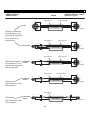
1
P-SER RIES MANUA AL P100 00X, P1500X X & P18 800SX Po owered d Loud dspeakkers Instrucction Manual (English) CERWIN-VEGA! PROFESSIONAL To avoid injury, read all operating instructions and safety information in this manual before using the speaker. Failure to follow these safety instructions could result in fire, electric shock, or other injury or damage to the speaker or other property. Contents IMPORTANT SAFETY INSTRUCTIONS ....................................................................................................................................... 3 REGULATORY CERTIFICATION ................................................................................................................................................. 5 Introduction ............................................................................................................................................................................ 6 Before you begin ..................................................................................................................................................................... 6 Quick Start............................................................................................................................................................................... 7 Loudspeaker placement .......................................................................................................................................................... 7 P1000X and P1500X Mixer - Rear Panel ................................................................................................................................. 8 P1800SX Mixer - Rear Panel .................................................................................................................................................. 11 P1000X, P1500X and P1800SX Power Connections - Rear Panel.......................................................................................... 13 Using the P1000X and P1500X as a floor/stage monitor ...................................................................................................... 14 Using the pole mount – P1000X only .................................................................................................................................... 14 Using the pole mount – P1500X only .................................................................................................................................... 15 Using the suspension points ................................................................................................................................................. 16 Application #1 – Single P1000X or P1500X ........................................................................................................................... 17 Application #2 – Adding a second P1000X or P1500X .......................................................................................................... 18 Application #3 – Adding Subwoofers .................................................................................................................................... 19 Application #3 – Adding Subwoofers (Adjusting HPF & LPF Filters continued) .................................................................... 20 Application #4 – Daisy-Chain ................................................................................................................................................ 21 Application #5 – Adding a P1000X or P1500X as a Stage Monitor ....................................................................................... 22 Application #6 – Large Venue/Front of House ...................................................................................................................... 23 Protective Grill ...................................................................................................................................................................... 24 Remote Main Volume ........................................................................................................................................................... 24 System Block Diagram (P1000X and 1500X full-range loudspeaker) .................................................................................... 25 System Block Diagram (P1800SX subwoofer) ....................................................................................................................... 25 Troubleshooting .................................................................................................................................................................... 26 Care and Maintenance .......................................................................................................................................................... 28 Appendix A – Cable Connections .......................................................................................................................................... 28 Warranty ............................................................................................................................................................................... 30 How to Obtain Warranty Service .......................................................................................................................................... 32 2 CERWIN-VEGA! PROFESSIONAL IMPORTANTT SAFETY INSTRUCTIIONS C CAUTION: Thee lightning flaash with an aarrowhead syymbol within an equilateraal triangle is intended to aalert the user to the presence of u un-insulated dangerous volttage within the unit’s enclo osure that mayy be of sufficieent magnitude to constitutte a risk o of electric sho ock to personss. W WARNING: Th he exclamatio on point within an equilateeral triangle is i intended to o alert the usser to the preesence of imp portant o operating and d maintenancee (servicing) in nstructions in tthe literature accompanying the productt. NOTE: The haand within an equilateral trriangle is inten nded to alert the user to specific guidan nce and inform mation regard ding the information reegarding the o operation of the unit, and should be read d fully before u using the unit for the first tiime. C CAUTION: To reduce the rissks of fire or eelectric shock do not removve any covers, or open the u unit. There aree no user-servviceable parts inside. All A servicing sh hould be referred to qualifieed service enggineers. a) Read d and follow alll the safety an nd operating iinstructions beefore connectting or using th his unit. b) Retaiin this user maanual for future reference. c) All w warning on the unit and its p packaging shou uld be read an nd followed. C CAUTION: To reduce the rissks of fire or eelectric shock do d not exposee this product to rain, moistture, dripping,, or splashing. Do not quid such as vvases or glassees on apparatus. Do not u use this product near waterr for example,, near a place objects containing liq n a swimm ming pool. Unplug the unit from the wall outlet before cleaning. Never N use thin nner, cleaningg fluids, bath tub, or near ssolvents or ch hemically imprregnated cloth hs. For cleanin ng always use a soft dry clo oth. Unplug th his product during lightning storms o or when unused for long peeriods of time. C CAUTION: Thee unit should be b installed so o that its locattion or positio on does not intterfere with itts proper venttilation. For exxample, it should not be situated o on a bed, sofa, rug or similaar surface thaat may block tthe ventilation n openings; o or placed in a built-in uch as a bookccase or cabineet, that may im mpede the flow of air throu ugh its ventilattion openings and/or fan asssembly. installation, su TThe unit shou uld be situated from heat ssources such as radiators, heat registerss, stoves or otther devices ((including amplifiers) tthat produce heat. No nakeed flame sourcces, such as ligghted candles,, should be plaaced on, or neear the unit. W WARNING: Do o not place this unit on an unstable su urface, cart, sttand or tripod, bracket or table. The unit may fall, ccausing sserious injuryy to a child or o adult and serious damage to the u unit. Use onlyy with a cartt, stand, tripo od, bracket o or table recommended d by the manufacturer. A Any mountingg of the device on a walll or ceiling should follow the manufaccturer’s instructions and should usse a mountingg accessory recommended d by the man nufacturer. An n appliance and cart ccombination sshould be moved with caare. Quick sto ops, excessive force and uneven surfaaces may cau use the aappliance and d cart combination to overturn. When a cart is used,, use caution when movingg the cart/app paratus ccombination to avoid injuryy from tip-over. NOTE: Should d the unit beco ome damaged d beyond repaair, or reachess the end of its life, please consult the rregulations reggarding d disposal of eleectronic produ ucts in your reegion. NOTE: Cerwin n-Vega cannott be held respo onsible for damage caused by improper use u of the unit and or the applications a prrovided ffor use with th he unit. TTO PREVENT EELECTRIC SHO OCK, MATCH THE WIDE BLAD DE OF THE PLU UG TO THE WIDE WALL SOC CKET SLOT AND FULLY INSER RT. TThe apparatuss shall be conn nected to a Mains M socket ou utlet with a prrotective grou und(earth) con nnection. 3 CERWIN-VEGA! PROFESSIONAL IMPO ORTANT SAFETY INSTRUC CTIONS (continued) 1. The unit an nd power supp ply should onlyy be connecteed to a power outlet that matches the vo oltage and freq quency as marrked on tthe rear of thee unit and pow wer supply. 2 2. Protect thee power cable from being w walked on or pinched particu ularly at plugs, conveniencee receptacles, and the pointt where tthey exit from m the apparatu us. 3 3. Do not deffeat the safetyy purpose of the polarized or groundingg-type plug. A polarized plu ug has two blaades with onee wider tthan the otheer. A groundingg type plug haas two blades and a third grrounding pron ng provided fo or your safety.. If the provided plug d does not fit in nto your outlett, consult a qu ualified electrician for replaccement of thee obsolete outtlet. 4 4. If the mains plug supplyiing this produ uct incorporattes a fuse then n it should on nly be replaced d with a fuse of identical o or lower rupture value. 5 5. Never use a damaged or frayed powerr cable; this caan cause serious risk of expo osure to lethal voltages. 6 6. The power cable of the u unit should be unplugged fro om the wall outlet when it iis not going ussed for a long period of time. 7 7. Only use attachments/acccessories specified by the m manufacturer.. 8 8. To complettely disconnecct the power in nput, the main ns plug of the speaker should be disconnected from th he mains connection. 9 9. The mains p plug of the apparatus should not be obstructed so it caan be easily acccessed duringg intended usee. DO NOT ATTEEMPT SERVICIN NG OF THIS UN NIT YOURSELFF. REFER SERVICING TO QUA ALIFIED SERVIC CE PERSONNEEL. original ment parts useed have the saame characteristics as the o In the event tthat servicing is needed, make sure that any replacem parts and thatt routine safetty checks havee been perform med to guaran ntee that the equipment is in safe operatting condition. REPLACEMENT WITH INCOR RRECT PARTS MAY RESULT IN FIRE, ELECTTRIC SHOCK O OR OTHER HAZZARDS. TThis unit shou uld be serviced d by qualified service person nnel when: TThe power cord or the plugg has been dam maged O Objects have ffallen, or liquiid has been sp pilled into the unit TThe unit has been b exposed to rain or liqu uids of any kind TThe unit does not appear to o operate norm mally or exhib bits a marked cchange in performance TThe device has been droppeed or the encllosure damageed. nded or intensse direct sunligght. The driver suspension ccould prematu urely dry out and a finished surfaces Keep speakerss out of exten may become d degraded by long-term exposure to inten nse ultra-violeet (UV) light. TThe speaker contains senssitive compon nents. Do nott drop, disasssemble, open n, crush, bend d, deform, pu uncture, micrrowave, incinerate, paint, or insert fforeign objectts into speakerr. TThe speakers are easily caapable of geneerating sound d pressure levvels (SPL) suffficient to causse permanentt hearing dam mage to production creew and audien nce members.. Caution shou uld be taken tto avoid prolonged exposurre to SPL in exxcess of performers, p 9 90 dB(A). O Operate and sstore the speaaker in a placee where the ttemperature is between -20 0° to 55°C. Low or high tem mperature con nditions might cause tthe speaker tto temporarilyy stop workin ng. Avoid dramatic changees in temperature or humidity when using the sspeakers as co ondensation may m form with hin the speakeer. TTurn the speaaker off when in any area w with a potentiaally explosive aatmosphere. Obey O all signs and instructio ons as sparks in such aareas could caause an explosion or fire reesulting in serious injury or even death. A Areas with pottentially explo osive atmosph here are o often but nott always marked clearly. Potential P areaas may include fueling areas, areas wheere the air co ontains chemicals or partials (including grain dust or metal paarticles) below w deck on boaats, fuel or ch hemical transffer storage faccilities, and an ny area yyou’d normallly be advised tto turn off you ur vehicle enggine. TThe speaker ccontains small parts, which h may presentt a choking haazard to small children. Keeep the speakeer and its acceessories aaway from sm mall children. 4 CERWIN-VEGA! PROFESSIONAL REGULATTORY CERTTIFICATION win-Vega declaares under ou ur sole respon nsibility that tthis product, to which thiss declaration relates, is in conformity with w the Cerw follow wing standard ds: The Declarations of Conformitty can be obttained from Gibson Europ pe BV - Kameerlingh Onnessweg, 2 - 413 31 PK Vianen n - The herlands Tel : ++31 347 32 40 0 10 - Fax : +31 1 347 32 40 15 5 Neth onditions: (1) this device m may not This device compllies with Part 15 of the FCC Rules. Operration is subjeect to the folllowing two co nd (2) this deevice must acccept any intterference recceived, includ ding interference that mayy cause cause harmful intterference, an on. undeesired operatio WARNING G: Changes orr modifications to this unit n not expressly approved by the t party resp ponsible for co ompliance cou uld void the user'ss authority to operate the eequipment. NOTE: Th his equipment has been tested and found d to comply with w the limits for a Class B digital device,, pursuant to Part 15 of the FCC C Rules. These limits are deesigned to pro ovide reasonaable protection n against harm mful interference in a residential installattion. This equ uipment geneerates, uses, and can radiatee radio frequeency energy an nd, if not instaalled and used d in accordancce with the insstructions, may cause harm mful interferen nce to radio communicatio ons. Howeverr, there is no o guarantee that interferen nce will not o occur in a particular instaallation. If this equipment does cause harrmful interference to radio or television reception, wh hich can be deetermined by turning the eequipment offf and on, the u user is encouraaged to try to correct the in nterference byy one or moree of the following measures: – Reo orient or reloccate the receivving antenna. – Inccrease the separation betweeen the equipment and receeiver. nnect the equ – Con uipment into aan outlet on a circuit differeent from that tto which the receiver is connected. – Con nsult the dealer or an experrienced radio TV technician n for help. This Class B digital apparatus co omplies with C Canadian ICES--003. 5 CERWIN-VEGA! PROFESSIONAL Introduction Congratulations - Welcome to the Cerwin-Vega! Family! You’ve joined a growing group of audio professionals who have turned to Cerwin-Vega! for the most advanced audio reproduction systems available. All Cerwin-Vega! products are thoroughly tested to insure that they meet or exceed our performance specifications. Backed by the best service in the industry, Cerwin-Vega! is dedicated to quality and reliability. For a complete overview of Cerwin-Vega! products and services, log onto www.cerwin-vega.com Before you begin The Cerwin-Vega! P-Series active speakers covered by this manual are designed for portable applications in which the speakers will be stacked directly on a floor, stage, stable platform, or mounted on a tripod stand or pole-mount. CerwinVega! does not support suspension of the subwoofer models covered by this manual nor are these models intended for fixed installation in outdoor or high moisture environments. Moisture can damage the speaker cone or surround and cause corrosion of electrical contacts so avoid exposing the speakers to direct moisture. Cerwin-Vega! speakers can generate considerable energy. When placed on a slippery surface such as polished wood or linoleum, the speaker may move due to its own mechanical vibration. Precautions should be taken to assure that the speaker does not fall off a stage or table on which it is placed. Some Cerwin-Vega! speakers include a receptacle cup to allow mounting of a satellite speaker on top of the subwoofer using a standard speaker pole shaft. When using a standard speaker pole shaft, be sure to observe the following precautions: CAUTION: There are a wide variety of pole stands and pole shaft available in the market. Please refer to qualified service personnel from the pole stands and pole shaft manufacturer for installation service. Improper use of accessory and inappropriate installation will present a tripping hazard. Check the speaker pole shaft specification to be certain it is designed to support the weight of the speakers. Observe all safety precautions specified by the speaker pole shaft manufacturer. Always verify that the subwoofer is placed on a flat, level, and stable surface. Route cables so that performers, production crew, and audience will not trip over them, toppling the speaker. Always be cautious in windy, outdoor conditions as the stability of the entire system may be compromised. 6 CERWIN-VEGA! PROFESSIONAL Quick Start The steps below provide a quick reference on how to setup and use a single loudspeaker. A typical setup will follow the same basic steps. STEP 1 STEP 2 Place the loudspeaker in the ideal location. See the Loudspeaker Placement page for recommended usage. Connect the source audio equipment output to the loudspeaker input. Be sure the source equipment is powered on and set to a normal output level. Make sure the loudspeaker is unplugged. Be sure the master switch is to set to the ‘OFF’ position. Turn the Volume to the lowest level (fully counter-clockwise) Check that the loudspeaker voltage selector is set to the same voltage as the AC power outlet. Connect the power cord to the loudspeaker and AC power outlet. Set the master power switch to the ‘ON’ position and verify the rear POWER LED indicator is illuminated. Slowly turn the volume clockwise until the sound output is at the desired level. If there is no sound, check to make sure the source equipment is providing audio output. STEP 3 When you are done using the loudspeaker, set the master power switch to ‘OFF’ before removing any cables and turning off the source audio equipment. NOTE(s) Do not switch the loudspeaker voltage selector or MIC/LINE switch while the loudspeaker is powered ‘ON’ and plugged into an AC power outlet. Loudspeaker placement Never point a microphone directly at a loudspeaker as this will result in extreme feedback (unwanted sound). Be sure the loudspeaker is placed away from the front of the microphone or directly behind the microphone when in a floor monitor position. When used with turntables, carefully place the loudspeaker so that any vibrations do not interfere with the turntable performance and functionality. Avoid placing the loudspeaker in the corners or along the walls of a room. This will increase the low-frequency sounds and the sound will result in a muddy and incoherent sound reproduction. Avoid placing the speakers directly on a hollow stage. It is better to place the loudspeakers on tripod stands or a sturdy table. The loudspeaker should be placed two to four feet above the ear level of the audience since the human body can absorb sound especially at high frequencies. This will make sure the entire audience can hear the sound system with the best possible clarity. 7 CERWIN-VEGA! PROFESSIONAL P10 000X and d P1500X X Mixer - Rear Pan nel The P1000X and P1500X pow wered loudsp peaker has aan assortmen nt of mixer ccontrols and connections that cover sseveral he P1000X/P1 1500X mixerr, as listed beelow, to takee full advantage of the product appllications. It iss suggested to review th ures. featu A B C J D I E H F G INPUT 1 (A) 1, INPUT 2, INPUT 3 LEEVEL KNOB BS h level knob adjusts a the ggain level on the respectivve input sign nal. The full clock-wise po osition (MAX)) sets the gain level Each to m maximum wh hereas a full counter-clo ockwise (MIN N) position sets s the gain n level to the minimum ‘MUTE’ leveel. It is reco ommended to set each leevel knob to o the middlee position an nd the main volume knob to the MIN N or fully co ounterclockkwise positio on when firstt connecting the system. (B) INPUT 1 1, INPUT 2 MIC/LINE SSWITCH pment conneected to INP PUT 1 and INPUT 2. Forr example, iif a microph hone is Set each switch according tto the equip nected to INPUT 1, set th he switch to ‘MIC’. If a m mixing conso ole or acousttic-electric gu uitar is connected then sset the conn switch to ‘LINE’. SW WITCH POSITTION M MIC LINE INPUT IMPEDAN NCE 2 kO Ohm 40 kkOhm p set to the devicce that is con nnected to tthe NOTE: The switcch must be properly input. Any mistakke may result in unexpeccted sound leevel. 8 CERWIN-VEGA! PROFESSIONAL (C) SIGNAL/CLIP INDICATORS Each of the three inputs is monitored by an indicator that provides status on the incoming audio signal. The SIGNAL indicator is illuminated when there is an audio signal present with a level greater than -30dBu, approximately the lowest level before a MUTE condition. The CLIP indicator is illuminated when the audio signal is clipping and adjustments must be made to avoid amplifier shutdown and poor sound quality. Adjustments to prevent clipping are made by reducing the input signal gain/level on the appropriate channel or reducing the volume level on your audio source, if possible. (D) INPUT 1 & INPUT 2 INPUT JACKS A combination input on each channel allows for either XLR or ¼” TRS cable types. (E) INPUT 3 INPUT JACKS A pair of ¼” TS unbalanced input jacks is provided on this channel for stereo connections such as a keyboard or media device. Devices with RCA outputs can use these inputs with the appropriate cable or plug adapter. Both input jacks on this channel are summed into one mono signal. (F) THRU 1 & THRU 2 The balanced XLR outputs THRU 1 & THRU 2 are parallel connections to the respective INPUT 1 and INPUT 2. The level controls for INPUT 1 & INPUT 2 will not affect the signal on the direct output connection. (G) MIX OUTPUT This is a balanced XLR output that is a sum of all three input channels. This output is not affected by changes to the Main Volume knob or the custom features but is affected by the levels set on each channel level knob. This connection is designed to provide an output which combines all three input channels together for connecting to another P1000X/P1500X powered speaker or a recording device. (H) MAIN VOLUME KNOB & REMOTE VOLUME CONTROL It is highly recommended to have the volume set to the minimal (MIN) level upon initial system start-up and it can be adjusted two different ways. On the main volume knob, volume is increased in a clockwise rotation and decreased in a counter-clockwise rotation. Another method to control the volume is by using the Remote connection (sold separately). A removable three-terminal jack can be wired over long distances to a remote volume control device with a corresponding connection. (I) INDICATORS Three indicators provide operating condition status on the P1000X/P1500X: 1) The POWER indicator (green) will illuminate when power is properly applied to the P1000X/P1500X and the main power switch is ‘ON’. 2) The LIMITER indicator (yellow) will illuminate when the P1000/P1500X automatically reduces the sound output to prevent damage to the speaker. While the P1000X/P1500X is producing sound, it is suggested to reduce the volume level so the LIMITER indicator does not illuminate. Continuing use of the P1000X/P1500X while this indicator is illuminated may result in a protect condition where no sound can be produced. 3) The PROTECT indicator (red) will illuminate when the P1000X/P1500X automatically places itself into a condition where sound output is shutoff. This condition may be the result of excessive limiting, an excessive heat condition, or a low voltage condition. These conditions all can cause significant damage to the product. 9 CERWIN-VEGA! PROFESSIONAL (J) CUSTOM FEATURES ENHANCED EQ SWITCH The ENHANCED EQ switch adjusts the contour of the overall frequency response and attenuates the mid-range frequencies which helps increase focus on the low and high frequencies while potentially reducing feedback. This feature is ideal for situations where an external mixer or EQ device is not available or playback only situations such as mobile DJ’s. It is recommended that users listen to their system with this switch both on or off to determine what is best for their needs. VEGA BASS BOOST SWITCH Engaging the VEGA BASS BOOST switch to ‘ON’ adds low frequency gain to the signal and dynamically adjusts the lowfrequency response based on the speaker volume level. Leaving the switch ‘OFF’ and engaging the HIGH PASS FILTER is recommended when using the P1000X/P1500X with a subwoofer. When using the P1000X/P1500X with the P1800X subwoofer it is also recommended to engage the HPF THRU & LPF SUB switch on the P1800X for the best performance. HIGH PASS FILTER SWITCH When engaged to ‘ON’, the HIGH PASS FILTER (HPF) switch attenuates overall frequency output below 80Hz. This is recommended to reduce stage rumble when the speaker is used as a floor monitor or in situations where low frequencies need to be attenuated such as in combination with a subwoofer. FRONT LIMITER LIGHT SWITCH Setting the FRONT LIMITER LIGHT switch to ‘ON’ will enable the limiter indicator light on the front of the P1000X/P1500X. This allows the user to see when the limiter is engaged in situations where it needs to be visible such as during a sound check. 10 CERWIN-VEGA! PROFESSIONAL P1800SX Mixer - Rear Panel The P1800SX powered subwoofer features an assortment of controls and connections similar to the P1000X/P1500X but unique to the needs of this subwoofer. It is suggested to review the P1800SX mixer, as listed below, to take full advantage of the product features. (A) SIGNAL/CLIP INDICATOR Each of the two inputs is monitored by an indicator that provides status on the incoming audio signal. The SIGNAL indicator is illuminated when there is an audio signal present with a level greater than -30dB, approximately the lowest level before a MUTE condition. The CLIP indicator is illuminated when the audio signal is clipping and adjustments must be made to avoid amplifier shutdown and poor sound quality. Adjustments to prevent clipping are made by reducing the input signal gain/level on the appropriate channel. (B) INPUT 1 & INPUT 2 INPUT JACKS A combination input allows for both XLR and ¼” TRS cable types. (C) THRU 1 & THRU 2 The balanced XLR output is a connection to the respective INPUT 1 and INPUT 2. Note, the HPF THRU & LPF SUB custom feature is placed between the INPUT and THRU. 11 CERWIN-VEGA! PROFESSIONAL (D) LINK OUTPUT This is a balanced XLR output that is the sum of the two input channels. This output is not affected by changes to the Main Volume knob or the custom features. This connection is designed to provide an output which combines both channels together for connecting to an additional P1800SX. (E) MAIN VOLUME KNOB & REMOTE VOLUME CONTROL It is highly recommended to have the volume set to the minimal (MIN) level upon initial system start-up and it can be adjusted two different ways. On the main volume knob, volume is increased in a clockwise rotation and decreased in a counter-clockwise rotation. Another method to control the volume is by using the Remote connection (sold separately). A removable three-terminal jack can be wired over long distances to a remote volume control device with a corresponding connection. (F) INDICATORS Three indicators provide operating condition status on the P1800SX: 1) The POWER indicator (green) will illuminate when power is properly applied to the P1800SX and the main power switch is ‘ON’. 2) The LIMITER indicator (yellow) will illuminate when the P1800SX automatically reduces the sound output to prevent damage to the speaker. While the P1800SX is producing sound, it is suggested to reduce the volume level so the LIMITER indicator does not illuminate. Continuing use of the P1800SX while this indicator is illuminated may result in a protect condition where no sound can be produced. 3) The PROTECT indicator (red) will illuminate when the P1800SX automatically places itself into a condition where sound output is shutoff. This condition may be the result of excessive limiting, an excessive heat condition, or a low voltage condition. These conditions all can cause significant damage to the product. (G) CUSTOM FEATURES POLARITY REVERSE In situations where the P1800SX is not optimally located, a polarity reverse switch is provided which inverts the phase of the audio signal by 180 degrees and can improve low frequency performance. In certain situations, the location of the subwoofer may be out of phase with the full-range speakers. By reversing the polarity of the subwoofer, the phase will match the full-range with the benefit of not having to relocate the subwoofer. VEGA BASS BOOST SWITCH Engaging the VEGA BASS BOOST switch to ‘ON’ adds low frequency gain to the signal and dynamically adjusts the lowfrequency response based on the subwoofer volume level. HPF THRU & LPF SUB When turned on, the HPF THRU & LPF SUB switch engages two filters simultaneously: 1) A low pass filter will attenuate frequencies above 80Hz for the P1800SX subwoofer. 2) A high pass filter will attenuate frequencies below 80Hz on the THRU 1 & 2 outputs. This is recommended when using the subwoofer in combination with other speakers such as the P1000X/P1500X. FRONT LIMITER LIGHT Setting the FRONT LIMITER LIGHT switch to ‘ON’ will enable the limiter indicator light on the front of the P1800SX. This allows the user to see when the limiter is engaged in situations where it needs to be visible such as during a sound check. 12 CERWIN-VEGA! PROFESSIONAL P10 000X, P1500X and d P1800S SX Powerr Connecttions - Re ear Panell The P1000X, P15 500X and P1800SX poweer connection ns are locateed on the reaar panel. It is suggested to understand the wer connectio ons and descriptions belo ow to insure proper use. pow (A) MAIN POWER P VOLLTAGE SELE CTOR The loudspeakerr can be used d with 100-1 120V AC or 220-240V AC power supply lines. Be sure the voltaage selector switch oper voltage before conn necting the p power cord. In addition, if the selecto or is adjusteed from its sh hipped is seet to the pro settiing, be sure the proper ffuse has been installed. A Any failure to meet these instruction ns may resultt in damage to the loud dspeaker. (B) POWER INLET & FU USE pe and shou uld only be used u with th he power corrd, or rated--equivalent, that is The power inlet is an IEC reeceptacle typ uded with thee loudspeakeer. inclu Belo ow the power inlet is the fuse holder that can onlly be accesseed when the power cord is removed. Be sure to replace r the fuse f with ratted-equivalen nt (see Specification section). (C) MAIN POWER P SWIITCH p to the loudspeaker. Be sure all connectionss and audio ssettings are sset at a The ON/OFF masster switch controls the power safe level beforee placing the loudspeakerr into an ‘ON’’ condition. FAN (D) matically conttrolled by the loudspeakeer and provid des air-flow ventilation for f the intern nal electroniccs. The The fan is autom nsure properr cooling air flow f to the eelectronics. fan sshould neverr be blocked in order to in 13 CERWIN-VEGA! PROFESSIONAL Usiing the P1 1000X an nd P1500 0X as a flo oor/stage e monitor The P1000X and d P1500X can n be used ass a floor mo onitor by layying the cabinet on its siide at a fixed 45 degreee angle ormers. It is recommendeed to engagee the HIGH P PASS FILTER w which cuts lo ow frequencies to minimiize any towaard the perfo low frequency b bass-couplingg or stage rumble r betw ween the loudspeaker and a the stagge platform. Be sure th hat the 00X/P1500X and cables are a not locatted where th hey can beco ome a trippiing hazard. Itt is recommended to use right P100 angle XLR or righ ht angle ¼” jaacks where possible p to avvoid cable bin nding betweeen the loudspeaker and sstage platform. Speaker directtion 45ºº Sttage Floor Usiing the po ole moun nt – P100 00X only The P1000X features a SHAFTT GRABBER p pole mount ccup that redu uces unnecesssary wobblee when the sspeaker is mo ounted ockwise until the pole caan fit into the pole moun nt cup. on a pole. To usse the SHAFTT GRABBER, spin the discc counter-clo Nextt, spin the SH HAFT GRABBER disc clockkwise until th he speaker haas a tight fit w with the speaaker pole. 14 CERWIN-VEGA! PROFESSIONAL Usiing the po ole moun nt – P150 00X only The P1500X hass two differeent pole mo ounting angles: level and d 7.5 degrees down. Th his ws the loudspeaker to bee adjusted to an angle thaat provides o optimal audieence coveragge. allow For example, a loudspeaker l may have th he pole mou unt placed on a raised stagge platform m usted to 7.5 d degrees downward so thee front audieence will not be missed. adju 7.5 0 Adju ust the pole mount angle on the lou udspeaker beefore it is pllaced onto a pole. On th he botttom of the lo oudspeaker iis a rotatable disc with ttwo tabs and d a position indicator. Use the ttwo tabs to rotate the disc so that th he position indicator is aligned with either e 0 (leveel) or 7..5 (angle dow wnwards). Bee sure the dissc ‘clicks’ into o place and ccannot rotatee freely. CAUTION N: When usin ng stands or poles, be sure to observee the following: Make sure the po ole stand is capable of handling the weight off the loudspeaker. Be su ure to observe all utions as indiicated by thee pole stand manufactureer. precau The po ole stand mu ust be placed d on a flat, leevel and stab ble surface with w the legs fully extended. The polee stand legs sh hould be placced where th hey will not p present a trip pping hazard.. Powerr cables and audio a signal cables must be placed in n a location where w they w will not create a tripping hazard or topple the speakkers over wh hen moved or pulled. When placing the loudspeakerss on top of th he pole stand d, be sure to ask for help. Beforee loudspeakeer pole moun nting, be suree to inspect aall critical points for any ccracks, deforrmations, corrrosion and/orr missing parrts that may aaffect the strrength and safety of the installation. Only use a pole staand intended d for loudspeaker use. p stand an nd loudspeakker in an areaa of traffic to o prevent acccidental contact. Avoid placing the pole ditional weigght to support (sandbags) on the basee of the polee stand In a wiindy environment, be sure to use add for add ditional stabiility. Do not attach a banneers, signage o or balloons to the pole sttand and/or the t loudspeaaker. Consult a licensed,, professionaal engineer reegarding equ uipment insttallation and ensure that all local, staate and ons regarding the safetty and operation of lo oudspeakers and relateed equipmen nt are national regulatio dhered to. undersstood and ad 15 CERWIN-VEGA! PROFESSIONAL Usiing the su uspension points The P1000X and d P1500X su uspension po oints are M10 threads h a depth of 2 25mm. with On tthe P1000X, two suspension points aare located on the top hand dle with fourr pull-back po oints located d on the rear of the unit. On tthe P1500X,, two suspension pointss are located on each hand dle (top for vertical orientation o and on thee side for horizzontal orienttation) as well as two pull-back poin nts located on th he rear of the unit. CAUTION N: When usin ng suspensio on installation n, be sure to observe thee following: Loudsp peaker suspeension requirres qualified persons who are familiaar with riggin ng standards and practicees. Any unsafee mounting o of any heavy load can resu ult in seriouss injury and equipment e daamage. Consult a licensed,, professionaal engineer reegarding equ uipment insttallation and ensure that all local, staate and ons regarding the safetty and operation of lo oudspeakers and relateed equipmen nt are national regulatio dhered to. undersstood and ad Do nott attempt to suspend thee loudspeakers by the han ndles. Beforee loudspeakeer suspension n, be sure to o inspect all critical poin nts for any ccracks, deformations, corrrosion and/orr missing parrts that may aaffect the strrength and safety of the installation. Only u use commerccially-availab ble M10 load d-rated shoulder eyebolts along with h rigging hardware appro opriate for thee actual load.. Fittinggs and riggingg hardware m may deterioraate over exteended period ds of time du ue to wear an nd/or corrosion, be he installed iss checked thoroughly by qualified personal at reggular intervals. sure th Cerwin n-Vega! cann not be held rresponsible ffor damage or o injury cau used by insuffficient stren ngth of the support structu ure or improper installation. Do not use the pull-back point as the susp pension pointt for a majo ority of the load. The pu ull-back poin nts are d for anglingg the loudspeaker dow wnwards onlyy. Note that the loudspeaker susp pension poin nts are intended intended d for one loudspeaker only. 16 CERWIN-VEGA! PROFESSIONAL App plication ##1 – Singlee P1000X or o P1500X X A sin ngle P1000X or P1500X powered speeaker can bee used to reiinforce soun nd for a widee variety of performancees. The diagram below shows s an ap pplication wh here a vocal microphonee, an acoustic-electric gu uitar and eitther a keybo oard or dia player aree used togetther. Each individual channel volumee can be adju usted to creaate the rightt balance wh hile the med main n volume kno ob controls the overall au udience volume. Eq quipment C Cable Type ut 1 Inpu Accoustic-Electtric Guitar (Seet switch to LINE) ¼ ¼” TS (standaard guitar cab ble) Inpu ut 2 M Microphone (SSet switch to o MIC) X XLR Inpu ut 3 Keeyboard (or media m playerr) D Dual ¼” TS (or RCA*) * Devvices with RCA outtputs can use INPPUT 3 with the apppropriate cable or plug adapters. 17 CERWIN-VEGA! PROFESSIONAL App plication ##2 – Addin ng a secon nd P1000X X or P1500 0X A second P1000X X or P1500X loudspeakerr can easily b be added usin ng a standard d XLR/mic caable as in thee example beelow. A udience and situations w where more vvolume is needed. To add d a second P P1000X two speaker systtem can coveer a wider au nect the MIX X OUTPUT of the first speaker to INPU UT 1 or INPUTT 2 on the seecond speakeer then or P1500X loudspeaker, conn d main volum me to an apprropriate setting on the first speaker. Be aware thaat the main volume v on th he first set tthe level and speaaker will not change the volume on the second speaker so m make sure to o set the inp put and main n volume kn nobs to similar settings. 18 CERWIN-VEGA! PROFESSIONAL Application #3 – Adding Subwoofers For demanding applications where even greater bass response is ideal, adding subwoofers to a pair of P1000X/P1500X speakers is a great idea. In the diagram below, an audio source is connected to INPUT 1 on each P1800SX subwoofer and then the signal is linked to the P1000X/P1500X speakers by using the P1800SX THRU 1 outputs. The P1000X/P1500X and P1800SX also have CUSTOM FEATURES that allow them to work together efficiently which is covered on the next page. AUDIO SOURCE P1500X Input 1 Equipment From P1800SX THRU 1 output Cable Type XLR P1800SX Input 1 Equipment From Audio Source Cable Type XLR or ¼” TRS 19 CERWIN-VEGA! PROFESSIONAL App plication ##3 – Addin ng Subwoo ofers (Adjusting HP PF & LPF Fiilters conttinued) Wheen using the P1000X/P15 500X and P18 800SX togeth her it is impo ortant to kno ow how to seet the HIGH PASS P FILTER switch on the P1000X/P P1500X and tthe HPF THR RU & LPF SUB B switch on the t P1800SX X so that both speakers w work well toggether. o that the usser can routte the audio o source to either the P P1000X/P150 00X or Fortunately, thiss system is designed so 00SX depend ding on the siituation. Thee settings below have beeen provided for f either settup. P180 SIGNAL FLO OW TOP (P10 000X/P1500X X) (P1800SX) to SIG GNAL FLOW BO OTTOM BO OTTOM (P180 00SX) to TOP (P1000X/ P1 1500X) AUDIO SO OURCE RECO OMMENDED D SETTINGS P1000X/150 00X: High Passs Filter is ON N P1800SX: HPF THRU & LLPF SUB is ON N P10 000X/P1500X X: High Pass Filter is OFF P18 800SX: HPF TTHRU & LPF SSUB is ON NOTE: Using a standaard speaker pole, p the P10 000X/P1500X X and P1800SSX active sub bwoofer creaate a mentary systeem that is eaasy to setup aand transporrt. complem 20 CERWIN-VEGA! PROFESSIONAL Application #4 – Daisy-Chain Some events may require several P1000X/P1500X speakers spread across a long distance or a large stage front to provide adequate sound reinforcement for the entire audience. Since there are multiple sources, the loop out from the mix output should be used to daisy-chain to the next P1000X/P1500X and then use the thru-out from the second speaker onward. Input 1 Equipment Microphone (Set switch to MIC) Cable Type XLR Input 2 Microphone (Set switch to MIC) XLR Input 3 MIX OUTPUT Player (Left-to-Left, Right-to-Right) P1000X/P1500X next in daisy-chain (Input 1, Set switch to LINE) ⅛” to dual ¼” TS( or RCA*) XLR * Devices with RCA outputs can use INPUT 3 with the appropriate cable or plug adapters. 21 CERWIN-VEGA! PROFESSIONAL App plication ##5 – Addin ng a P1000 0X or P150 00X as a Stage S Mon nitor In a live perform mance, the p performer m may wish to have a stagge monitor tto help hearr the perform mance betteer. The X/P1500X sp peakers diagram below sshows a P1000X/P1500X used as a sttage monitor for the perrformer pluss two P1000X performer(s)) may have a different m mix requirem ment than th he audience which (daissy-chained) ffor the audience. The p meaans all the TH HRU outputs from the perrformer(s) m must be taken n to the first loudspeaker used to coveer the audien nce. At the first loudspeeaker, the in nput levels can be mixed d to the prefferred preseentation for tthe audiencee. The perfo ormer’s nitor can be m mixed to the performer’ss specific requirements w without affectting what thee audience hears mon NOTE: C Careful posittioning of th he monitor loudspeakerr is required d as the pro oximity to tthe microphone is susceptible to feedbaack. As a gen neral rule, neever point thee microphone towards th he loudspeakker. 22 CERWIN-VEGA! PROFESSIONAL Application #6 – Large Venue/Front of House In larger venues the Front of House engineer has control of the entire sound reinforcement system using the console mixer. The diagram below shows how a console mixer interfaces with the performers’ on-stage audio equipment with several P1000X/P1500X speakers directed towards the audience. 23 CERWIN-VEGA! PROFESSIONAL Pro otective G Grill The P1000X, P15 500X and P18 800SX are sh hipped with the t grill attached. It is reecommended d to leave the grill in placce as it neral use. will prevent any accidental damage to thee drivers that may result during transsportation, seetup and gen he event thaat the grill n needs to be removed, ssimply removve the hex-h head screws around thee edge of the grill. In th Rem move the grill slowly to aavoid damaging the gaskket. When reeplacing the grill, be suree the gasket is in place aand all fasteeners are seccured in tighttly to preven nt rattling during general use. Rem mote Maiin Volum me The 3-pin termin nal connecto or plug allow ws the P1000 0X, P1500X or o P1800SX m main volumee level to bee controlled ffrom a ote location through sign nal wires and an externaal device (no ot included). The signal w wire passes o only a voltage level remo and not the actu ual audio sign nal. A single d device can co ontrol the main volume o of multiple units when co onnected corrrectly. nd specified tto support nu umerous rotations as req quired for volume control use. The potentiometter should bee 10kOhm an NOTE: Do not usse the remotte main volume connection for anyth hing other th han may volume control tthrough the external devvice. Failure tto follow thiis warning m result in damage to the loudsspeaker. First Loudspeaker Second d Loudspeakker ccw w cw Vo olume Poten ntiometer 24 Third Loudspeaker and a on... CERWIN-VEGA! PROFESSIONAL Sysstem Blocck Diagra am (P100 00X and 1500X 1 full-range loudspea aker) Sysstem Blocck Diagra am (P180 00SX subw woofer) 25 CERWIN-VEGA! PROFESSIONAL Troubleshooting Problem No Sound No Power Shutdown Cause Loudspeaker is not connected to active AC power Loudspeaker power switch is in the ‘OFF’ position Input level is set to minimum setting Main volume is set to minimum setting Audio source is not active, volume is set too low, or poor connection Loudspeaker is not connected to active AC power Loudspeaker power switch is in the ‘OFF’ position AC power source voltage is too low or high Loudspeaker fuse is blown Loudspeaker protection Solution Verify the loudspeaker is indeed connected to an active AC power source. Various outlets may need to be switched ‘on’. Use a lamp as another way to be sure the AC power source is active. Verify that the power switch on the back of the loudspeaker is ‘ON’. Set the input level to a setting where sound can be heard. Set the volume level to a setting where sound can be heard. Use the Signal indicator on the back of the loudspeaker to verify an audio signal is indeed present. Verify that the audio equipment is turned ‘ON’ and set to output an audio signal at a volume level above minimum. Verify the cable connection from the audio source output to the loudspeaker input is correct. Audio mixers may have a MUTE or LOOP switch that may need to be disengaged. Microphones that require phantom power must be used with an external power source. Verify the loudspeaker is indeed connected to an active AC power source. Various outlets may need to be switched ‘ON’. Use a lamp as another way to be sure the AC power source is active. Verify that the power switch on the back of the loudspeaker is ‘ON’. Verify if the AC power source is too low or too high. The loudspeaker will protect itself if the AC power source is 10% lower or 10% higher than the loudspeaker’s intended voltage setting. Disconnect all power connections and inspect and replace, if necessary, the fuse located on the rear of the loudspeaker. See Specifications for fuse information. self- Avoid placing the loudspeaker near a heat source or under direct sun light. Avoid using an audio source with clipped and/or distorted input signal. Verify the limiter indicators are not always on and if so, lower the input and volume levels until the limiter indicator is ‘OFF’. 26 CERWIN-VEGA! PROFESSIONAL Troubleshooting (continued) Bad Sound Equipment settings Check the meters on the external mixing console to ensure that the signal is are not set properly not being clipped by the mixer, if the levels from the mixer are too hot causing distortion correct the gain structure of the console; first by lowering the pre-amplifier trim (input sensitivity), if this does not lower the signal level sufficiently then lower the channel fader, and if the level is still too hot then lower the master bus (but most likely a clipped input is the source of the distortion). It is important to check every active input channel on the console to ensure that each input trim is set correctly for each source. If the signal sources are plugged directly into the P1000X/P1500X make sure that the input level knobs are not turned up too high. If the signal indicator LED is turning RED on any channel that means the input on that channel is clipping and the input level needs to be lowered. It is also possible that the source level will need to be lowered. If distortion is still audible after lowering the source level and input level knob then lower the master volume knob on the P1500X. Check that the audio source and/or mixer do not have excessive bass or treble added to the mix, overdriven EQ’s can clip causing audible distortion. Bad cable connections Verify that all connections are good. Verify the connectors are clean and free of any residue build-up. Verify the insulation jacket on all cables has not been torn or crushed. Rattling Sounds Be sure the rattling sounds do not come from the caster wheels (subwoofer only), loudspeaker stands or any furniture or fixtures located near the system. Bad AC mains cable Avoid using an AC power source that is connected to a light dimmer. Use an AC location filter box or use a different AC circuit. Avoid routing the audio signal cables along other power cables, transformers and signal cables to prevent interference. Ground loop ‘hum’ Turn all volume and input levels to the minimum setting to verify there is no ‘hum’ coming from the connected audio equipment. If the ‘hum’ is still present, than remove all audio cable connections and if the ‘hum’ disappears than there is a potential ground loop problem. Ground lifting the signal cable (with a direct box or coupling transformer) is the safest way to eliminate ground loops within sound setups. Plug all audio equipment AC power connections into the same outlet which shares a common ground (make sure the outlet is capable of supporting the equipment to avoid overloading the circuit). Verify that the distance between AC power source and common ground is as short as possible. Equipment ‘hiss’ Use a balanced connection (instead of an unbalanced connection) to take advantage of the best noise rejection. Plug all audio equipment AC power connections into the same outlet which shares a common ground (make sure the outlet is capable of supporting the equipment to avoid overloading the circuit). 27 CERWIN-VEGA! PROFESSIONAL Care and Maintenance Before any cleaning or maintenance, be sure the loudspeaker is unplugged, turned off, and that all cables are removed. Be sure to avoid any moisture coming into the openings of the speaker. The loudspeaker can be maintained cosmetically using a dry cloth. Avoid using cleaning chemicals as they may harm the finish of the loudspeaker. A direct burst of air should be avoided and may harm the drivers as well as assisting debris into the enclosure. When storing the loudspeaker, be sure it is above ground to avoid accidental flooding and excess dust build-up. It is suggested to cover the loudspeaker while it is placed in storage or being transported. Appendix A – Cable Connections Hot (positive) 2 Hot (positive) Cold (negative) 3 Shield 1 Cold (negative) Shield XLR Balanced Input Sleeve Ring 1/4” TRS Balanced Tip Sleeve Ring Tip Hot (positive ) Cold (negative ) Shield Sleeve Sleeve 1/4” TS Unbalanced Tip Signal Tip 28 Ground CERWIN-VEGA! PROFESSIONAL REMOTE DEVICE DESCRIPTION REMOTE SIDE OF CABLE (Connector Type) CABLE Hot (positive) Cold (negative) 2 A. XLR** 2 3 3 Shield/GND (XLR) 1 1 Floating or Balanced low impedance: most professional equipment line in and line out, microphones. Hot (positive) Cold (negative) 2 T R S B. TRS PHONE 3 Shield/GND (XLR) 1 Hot (positive) Cold (negative) 2 T S Unbalanced C. STANDARD low impedance: some PHONE professional equipment and microphones. 3 Shield/GND (XLR) 1 Hot (positive) Cold (negative) 2 T S D. STANDARD PHONE 3 Shield/GND Unbalanced high impedance: most hi-fi equipment. (XLR) 1 Hot (positive) T S S E. SHIELD/GND PHONE Unbalanced high impedance: most hi-fi equipment. T Shield/GND (Standard Phone) 29 CERWIN-VEGA! PROFESSIONAL Warranty Thank you for choosing one of Gibson Pro Audio’s brands (Stanton, KRK, or Cerwin Vega!). Your satisfaction is extremely important to us. We proudly stand behind the quality of our work and appreciate that you put your trust in us. Registering your merchandise will help us guarantee that you are kept up to date on our latest advances. To Register Merchandise Purchased from an Authorized Gibson Pro Audio Dealer in the U.S.: Please go to: http://www.gibson.com and register online. Or you may send your warranty card to: Gibson Customer Service 309 Plus Park Blvd. Nashville, TN 37217 If you have any questions you may contact customer service at: 1-800-4GIBSON (1-800-444-2766) e-mail: [email protected] FOR MERCHANDISE PURCHASED FROM AN AUTHORIZED GIBSON PRO AUDIO DISTRIBUTOR OUTSIDE OF THE US, PLEASE CONTACT THE DISTRIBUTOR FROM WHOM YOU PURCHASED YOUR MERCHANDISE FOR TO REGISTER YOUR WARRANTY AND FOR HANDLING AND RESOLUTION OF ALL WARRANTY-RELATED ISSUES. Gibson Pro Audio Warranty If at any time your Gibson Pro Audio product (which includes Stanton, KRK, or Cerwin Vega! brands) malfunctions as a result of faulty materials or workmanship, Gibson Pro Audio or one of Gibson Pro Audio’s Authorized Service Centers in the US will repair the defect(s) or replace the merchandise, as it deems appropriate at its sole discretion. Warranty Period (from date of Purchase as listed on the Bill of Sale): Stanton One (1) year for all Stanton products. KRK Three (3) years from all studio monitors. One (1) year all headphones, computer audio devices, including room correction devices. Cerwin Vega! Five (5) years for all passive speaker systems. Three (3) years for all active speaker systems. Three (3) years for all mixers. Gibson will warrant all replacement parts and repairs for ninety (90) days from the date of original shipment. In the unlikely event that your merchandise is destroyed, lost or damaged beyond repair while in the possession of Gibson or one of Gibson Pro Audio’s Authorized Service Centers for repair, Gibson will replace that merchandise with one of the same or most similar style of a value not in excess of the original purchase price of your merchandise. Any insurance covering the merchandise, including but not limited to collector's value insurance, must be carried by owner at owner's expense. For the fastest and safest merchandise return, please use the original shipping carton and packaging materials. Gibson cannot be responsible for any damages incurred during the shipping process due to poor or inadequate packing. 30 CERWIN-VEGA! PROFESSIONAL THIS WARRANTY IS EXTENDED TO THE ORIGINAL RETAIL PURCHASER ONLY AND MAY NOT BE TRANSFERRED OR ASSIGNED TO SUBSEQUENT OWNERS. IN ORDER TO VALIDATE YOUR WARRANTY, AND AS A CONDITION PRECEDENT TO WARRANTY COVERAGE HEREUNDER, YOU MUST REGISTER YOUR WARRANTY WITHIN FIFTEEN (15) DAYS FOLLOWING THE ORIGINAL DATE OF PURCHASE.YOUR PROOF OF PURCHASE OR SALES RECEIPT MUST ACCOMPANY ALL REQUESTS FOR WARRANTY COVERAGE. This warranty is subject to the following limitations: THIS WARRANTY DOES NOT COVER 1. Any merchandise that has been altered or modified in any way or upon which the serial number has been tampered with or altered. 2. Any merchandise whose warranty card has been altered or upon which false information has been given. 3. Any merchandise that has been damaged due to misuse, negligence, or improper operation. 4. Any merchandise that has been damaged by accident, flood, fire, lightening, or other acts of God. 5. Shipping damage of any kind. 6. Any merchandise that has been subjected to extremes of humidity or temperature. 7. Any merchandise that has been purchased from an unauthorized dealer, or upon which unauthorized repair or service has been performed. GIBSON MAKES NO OTHER EXPRESS WARRANTY OF ANY KIND WHATSOEVER. ALL IMPLIED WARRANTIES, INCLUDING WARRANTIES OF MERCHANTABILITY AND FITNESS FOR A PARTICULAR PURPOSE, EXCEEDING THE SPECIFIC PROVISIONS OF THIS WARRANTY ARE HEREBY DISCLAIMED AND EXCLUDED FROM THIS WARRANTY. SOME STATES AND/OR COUNTRIES DO NOT ALLOW THE EXCLUSION OR LIMITATION OF IMPLIED WARRANTIES SO THAT THE ABOVE MAY NOT APPLY TO YOU. GIBSON SHALL NOT BE LIABLE FOR ANY SPECIAL, INDIRECT CONSEQUENTIAL, INCIDENTAL OR OTHER SIMILAR DAMAGES SUFFERED BY THE PURCHASER OR ANY THIRD PARTY, INCLUDING WITHOUT LIMITATION, DAMAGES FOR LOSS OF PROFITS OR BUSINESS OR DAMAGES RESULTING FROM USE OR PERFORMANCE OF THE MERCHANDISE, WHETHER IN CONTRACT OR IN TORT, EVEN IF GIBSON OR ITS AUTHORIZED REPRESENTATIVE HAS BEEN ADVISED OF THE POSSIBILITY OF SUCH DAMAGES, AND GIBSON SHALL NOT BE LIABLE FOR ANY EXPENSES, CLAIMS, OR SUITS ARISING OUT OF OR RELATING TO ANY OF THE FOREGOING. FOR MERCHANDISE PURCHASED FROM AN AUTHORIZED GIBSON PRO AUDIO DISTRIBUTOR OUTSIDE OF THE US, PLEASE CONTACT THE DISTRIBUTOR FROM WHOM YOU PURCHASED YOUR MERCHANDISE FOR THE HANDLING AND RESOLUTION OF ALL WARRANTY ISSUES. FOR THESE PURCHASES, THE ABOVE-DESCRIBED WARRANTY IS NOT APPLICABLE. 31 CERWIN-VEGA! PROFESSIONAL How to Obtain Warranty Service Warranty Service outside the United States: To initiate a warranty repair, please contact the Authorized Gibson Pro Audio distributor from whom you purchased your merchandise, and follow the distributor’s return/warranty policy. Warranty Service for Merchandise Purchased from an Authorized Gibson Pro Audio Dealer in the U.S: In the event of malfunction of your Gibson Pro Audio merchandise, the Dealer or Owner must call Customer Service @ 1-800-4GIBSON (1-800-444-2766) and obtain a Return Authorization number from the customer service agent. No merchandise may be returned to Gibson without such prior Return Authorization, and the Return Authorization number must be written on the outside of the shipping package. The Customer Service agent will provide the address and additional shipping instructions. Owner must ship the merchandise, freight, and insurance pre-paid to the address provided by the customer service representative. Only Authorized Gibson Pro Audio Service Centers may perform warranty service and any service performed by unauthorized persons will void this warranty. Gibson disclaims liability for defects or damage caused by services performed by unauthorized persons or non-warranty service not performed by Gibson or an Authorized Gibson Pro Audio Service Center. When contacting Gibson, you must include a complete written description of the malfunction of the merchandise. If non-warranty work is required or recommended, a quotation will be issued and must be approved by you before any non-warranty work is commenced. You should consider quotations obtained for non-warranty work immediately and advise the Authorized Gibson Pro Audio Service Center or Gibson of your wishes. You are not required to purchase nonwarranty work in order to obtain service on materials covered by this warranty. Following its inspection of merchandise upon its arrival, Gibson or the Authorized Gibson Pro Audio Service Center will advise you or your dealer of the approximate date of completion. The repaired merchandise or part will be returned to you or your dealer, freight collect insured. No representative or other person is authorized to assume for Gibson any liability except as stated in this warranty. This warranty gives you specific rights which vary from state to state or from country to country. For further information, write: Customer Service Dept., Gibson Customer Service 309 Plus Park Blvd. Nashville, TN 37217 Or call: 1-800-4GIBSON 32