1
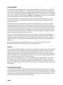
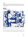
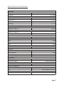
02
m5
500 series Opto Compressor Module
owner’s manual Rev A
all contents © Grace Design/ Lunatec LLC
2434 30th Street, Boulder, CO 80301 USA
tel 303.443.7454 fax 303.444.4634
[email protected] / www.gracedesign.com
Welcome and thanks for purchasing the Grace Design m502 optical compressor. We build all of
our products to be completely reliable and easy to use, so you can concentrate on making great
recordings. While you will find the m502 is completely straightforward to use, we do ask that you
spend a little time reading this manual to help avoid any common user difficulties.
In the event that you do encounter any technical difficulties with this or any of our products, feel free
to call us at 303-443-7454. Our office hours are 9:00 to 5:00, Monday through Friday, MST, or you may
e-mail any technical questions to: [email protected]. Also, please check out our web site for
complete product information, owner’s manuals and technical documents.
Grace Design has been building audiophile quality products for the recording industry for over
18 years. The technology in the m502 is the result of extensive listening, field-testing and careful
refinement. Your m502 represents a combination of absolutely pristine audio performance, robust
mechanical construction and complete reliability at a reasonable price.
We sincerely hope our products help you achieve a new level of excellence in your work!
- The Grace Design Team
Contents
Important Safety Information
3
Safety Marking Symbols
3
Features4
Front Panel Controls / Features
4
Installing and Connecting
5
Operation6
Diagrams9
Specifications (Preliminary)
11
Warranty12
Manual Revisions
page 2
13
Important Safety Information
GENERAL
Indoor use only
Ordinary Protection: This equipment should not be exposed to dripping or splashing.
Avoid placing objects filled with liquids, such as vases or glasses, on this equipment.
Mains supply voltage fluctuations are not to exceed ±10% of the nominal supply voltage.
Pollution Degree 2
Maximum Relative Humidity: <80%
Operation temperature range: 10 °C to 40 °C
Storage and transportation temperature range –40 °C to 70 °C
Maximum altitude: 3000m (9843 ft.)
Equipment suitable for continuous operation
Weight: 316g / 0.7 lb
SAFETY
Please be sure to power off your 500 series rack before installing or removing this or any
500 series modules. Hot swapping could cause connection sparks at the card-edge
connector that could damaging this or other equipment.
SERVICE INFORMATION
The Grace Design m502 contains no user serviceable components. Contact Grace Design for repair
and upgrade information. In the event that your Grace Design m502 needs to be returned to the
factory, please contact us for a return authorization number.
page 3
Features
•
Elegantly simple, purist feedback design optical compressor for signal leveling with a minimum of
sonic artifacts
•
Subtle dynamic control to heavy compression, the sonic character of the source remains intact
•
Comprehensive control set includes input level, threshold, attack, release, ratio and makeup gain
•
Bright, easy to read 10 segment LED gain reduction meters
•
Bi-color output peak LED lights green with signal present and red 6dB before clipping
•
Pin 7 & 9 connections to Radial Workhorse™ and Purple Sweet Ten™ auxiliary connectors
•
Pin 11 unbalanced audio out connection to Radial Workhorse™ BussFeed
•
Five year transferable warranty on parts and labor
•
Made in the USA
Front Panel Controls / Features
THRESHOLD - This knob sets the
minimum level at which the
compressor circuit is activated, with a
range of +15dB to -15dB.
ATTACK (milliseconds) - This knob sets
how quickly (or slowly) the compressor
circuit attenuates the incoming signal.
RELEASE (seconds) - This knob sets
how quickly (or slowly) the compressor
circuit releases its attenuation of the
incoming signal.
RATIO - The ratio control determines
the input/output ratio for signals
above the threshold level. Higher
ratios result in more aggressive gain
reduction while lower ratios will result
in more gentle gain reduction.
OUTPUT - The output control provides
20dB of variable level control at the
output of the m502, from -10dB to
+10dB. This control is useful for small
level adjustments during tracking or
for compression gain makeup.
page 4
COMP IN SWITCH - This switch
activates the compressor circuitry.
INPUT - This switch selects between
three input levels: -10dB, 0dB, and
+10dB.
LINK - This switch is to activate either
a) linking of two m502’s for use in
stereo compression scenarios, or b) to
activate external side chain control of
the compressor for ducking, de-essing
etc.
GR METER - This 10 segment meter
displays the amount of gain reduction
being applied to a signal in the
compression circuit.
PEAK INDICATOR - The LED peak
indicator, which monitors the signal
at the output of the compressor,
illuminates green at -10dBu and red at
+20dBu (6dB before clipping).
Installing and Connecting
Before you do anything, please register your unit with us as soon as possible. We provide a 5 year
transferable warranty on all of our products and registering it with us makes is easy if and when help
becomes necessary. So please take a few minutes to complete the enclosed warranty registration card
and mail it in, or simply fill out the warranty registration form on our web site. Thank you!
Installing the m502 in a 500 series rack
1. Open your m502 box. The module is in a bag under the plastic ‘korvu’ retaining sheet, which you
should be careful not to cut. Simply fold down the outer cardboard flaps, then the under side
flaps, which will loosen the module from under the plastic sheet.
2. Turn off your 500 series rack frame (hot swapping 500 series modules = bad). Inspect the card slot
you intend you use to make sure that it is clean and free of any debris.
3. Before removing your m502 from its anti-static bag, discharge any static electricity buildup you
may have by touching your 500 series rack or other gear that is properly grounded.
4. Pull your m502 module out of its anti-static bag and carefully slide it into place in the designated
opening. Sight down the back of the module (use a flashlight if necessary) and ensure the card
edge connector is aligned to seat into the card slot of the frame.
5. Firmly and evenly push the m502 module into place until its is positively seated in the card slot.
6. Use the 2 supplied #4-40 hex head screws and 3/32” hex wrench to mount the m502 front panel to
the 500 series rack. These screws can have a tight fit so please be careful not to cross thread them.
7. Plug your 500 series rack back into the AC source and power up your rack. Your m502 will
automatically power up with your 500 series rack.
BALANCED LINE INPUT
The m502 line input is located on the back of your 500 series rack. This connector should be wired pin
2 positive, pin 3 negative and pin 1 ground (check with your rack manufacturer’s documentation for
connector details).
BALANCED LINE OUTPUT
The balanced XLR line output connector is located on the back of your 500 series rack. This connector
should be wired pin 2 positive, pin 3 negative and pin 1 ground (check with your rack manufacturer’s
documentation for connector details).
OTHER CARD CONNECTIONS
In addition to the basic I/O provided on the back of the 500 series rack, there are a couple other
options for signal routing available on the m502 depending on which 500 series rack you are using.
Typically, 500 series module card edge pins 7, 9 and 11 are left unconnected. However, Radial
Engineering and Purple Audio both implement these locations in useful ways, so we have added
connections to them.
•
Pin 7 is connected to the ring of the 1/4” TRS connector labeled “OMNIPORT” on the Radial
Workhorse or “OPT IN” on the Purple Sweet Ten Rack for stereo linking of two m502’s.
page 5
•
Pin 9 is connected to the tip of the 1/4” TRS connector labeled “OMNIPORT” on the Radial
Workhorse or “OPT IN” on the Purple Sweet Ten Rack for stereo linking or side chain signal input.
•
Pin 11 is connected to send an unbalanced audio output to the Radial Workhorse “BUSS FEED”.
If you are using either of these racks, please refer to their documentation for operating with these
connections. Also, please refer to the ‘Card Edge Connector’ and ‘Jumper and DIP switch locations’
diagrams on pages 9-10 of this manual.
Operation
The compressor circuit is based on an optical attenuator - the purest, high fidelity gain control
mechanism available. It provides gentle to fairly heavy compression, while remaining neutral and
transparent. This compressor is not designed for “brick wall” limiting.
Similar to an eq, dynamic range compression is a subjective tool – there is no wrong way to use it.
However, using a compressor in a way that produces the best results can be tricky, and the more you
know, the better it will work. If you are unsure about how a compressor works, we highly recommend
some preliminary reading:
http://en.wikipedia.org/wiki/Dynamic_range_compression
It will pay greatly to understand the mechanism of dynamic range compression BEFORE you begin to
record keeper tracks with the compressor on.
SETTING THE INPUT TRIM
This switch selects between three input levels: -10, 0, and +10dB. Select the setting which best suits
the level of the incoming line signal and how much compression you require. This setting is interactive
with the threshold control, as a higher input level setting will result in a relatively higher threshold
setting to achieve the same amount of gain reduction. This control effectively sets how hard you drive
the compressor circuit.
SETTING THE THRESHOLD
The threshold is the level at which the compressor begins to attenuate the incoming signal. A high
threshold setting (counterclockwise) will result in only the dynamically highest passages of the signal
being attenuated, while everything below that threshold is unaffected by the circuit. Conversely, a
lower threshold means more of the signal at the input of the circuit will be attenuated resulting in
more compression.
Begin with the knob fully counterclockwise and the compressor switched ON, then slowly begin
turning clockwise until you begin to compress the signal. You will hear the signal compress, and you
will begin to see the GR meter light up. The lower the threshold setting, the more the incoming signal
will be attenuated and the more lights will light up on the GR meter.
SETTING THE ATTACK RATE
The rate at which you want the compressor to start the attenuation of the signal (attack phase)
depends on the character, or envelope, of the signal entering the compressor. If the signal has sharp or
fast attack (percussive sounds, snare drum) that you wish to attenuate, select a fast attack rate to sense
the initial impulse of the signal and attenuate it in time. If you want the compressor to react slower and
page 6
not attenuate the initial impulse of the signal, select a longer attack time. Using a slower attack time
may be more appropriate with signals with a slower, more gradual envelope (strings, woodwinds).
SETTING THE RELEASE RATE
The rate at which you want the circuit to release its attenuation of the signal (release phase) is set with
the release control. This is the functional opposite of the attack control. If the signal has a shorter
decay, it may be best to set a shorter release time. A helpful approach to setting the attack and release
time may be to consider the basic pulse of the signal you’re compressing. To avoid the typical artifact
known as ‘pumping’, where you can clearly hear the compressor working, it is important to set the
attack and release times to match the signal to where they are moving naturally with the dynamic and
rhythmic fluctuations of the signal.
SETTING THE RATIO
The compressor’s ratio control is used to set input/output ratio of signals above the threshold. For
instance, a setting of 3:1 means that if the incoming signal is 3dB over the threshold level, that signal
will leave the compressor around 1dB over the threshold level. The highest setting of this control is
12:1, meaning that signals far over the threshold setting are reduced by a much higher ratio – more
compression. So lower ratio settings mean lighter compression amounts. We recommend starting
with lower ratios and working upward as necessary.
LINK
This feature is used to link two m502 compressors together for stereo bus compression. In this mode,
the side chain signals of both units are summed together into one. To operate in stereo link mode,
both modules need to be connected together (see below) and both set to ‘link’ mode. With two units
linked, one is the master and the other the slave, with the master’s controls setting the compression
threshold, attach and release of both units. The slaved unit’s threshold control must be set to the
highest, full counterclockwise position.
NOTE: The RATIO controls are not summed, and must be set the same on both units. Due to slight,
unavoidable variances in the opto coupling devices, completely summing the side chain signals may
result in a subtle shift in the stereo field one direction or the other. So the RATIO controls remain
independent to allow you to make final, subtle corrections to the centering of the stereo image by ear.
LINK CONTROL CONNECTIONS
Stereo linking with the supplied jumper cable requires that both m502 modules be removed from
the rack so the cable can be connected to both units’ headers - labeled J5 (page 9). Once connected
together, gently slide both modules into two adjacent slots in your rack, making sure the jumper cable
is cleanly routed under or over the right hand module and does not catch on anything in the rack.
Carefully insert both modules all the way back until they just meet the card slot. Then fully seat each
module one at a time into their respective card slot connectors.
Alternately, you can connect two m502’s for stereo link control via the Radial Workhorse’s ‘Omniport’
or the Purple Audio Sweet Ten’s “Opt In”. In this setup you will need to connect a 1/4” TRS jumper
between the rack’s two aux jacks. The two m502 modules are then connected via pins 7 (ring) and 9
(tip), which then must be switched on at the m502’s DIP switch locations S5 SW1 & SW2 (page 9).
With any link scenario, make sure both m502’s ‘link’ switches are switched on (to the right).
page 7
SIDE CHAIN CONTROL
For connecting a side chain signal to the m502, you need a 500 series rack which has a provision for
an auxiliary input to the module via pin 7 (Radial Engineering Workhorse or the Purple Audio Sweet
Ten win again in our book). Connect an unbalanced side chain signal via the tip of a 1/4” TRS cable to
the aux in. This signal will be available for side chain input via pin 7. This pin must also be switched on
at the m502’s PC board DIP switch location S5 SW2, and the S4 SW1 (page 9) must be switched off,
which will disconnect the link internal audio path from the side chain input.
Normally, the compressor’s side chain circuit uses the internal audio signal to trigger its response.
But in side chain mode, the side chain circuit uses the external signal input to determine how the
compressor responds.
Examples of using an external side chain signal include ducking and de-essing. Ducking is an effect
used to automatically reduce the level of one signal when another signal is present. Think of a DJ’s
microphone automatically reducing the level of the music when they are speaking. It involves routing
a separate signal from a microphone (or any other source) into the side chain input of the m502. This
signal is what the compressor reacts to and thereby would typically reduce (or duck) the level of the
main signal in the m502. You would use the compressor controls to determine the amount, rate and
duration that incoming signal ducks the main signal.
De-essing is used to decrease excessive sibilant (‘s’ or ‘sh’) sounds in a voice. This is accomplished
by inserting a copy of the signal into the side chain input which has been equalized (by an external
equalizer) to emphasize the frequency where the sibilance lies (usually 6-9k). This inserted signal
makes the compressor react to and thereby reduce only the places in the signal where troublesome
sibilance lies.
There are many other functional and creative ways to use side chain input, more than can be
illustrated here. Again, the more you know, the more powerful it can be.
GR METER
This meter shows the amount of gain reduction being applied by the compressor. The LED’s illuminate
top to bottom, with one LED representing 1dB of gain reduction and ten LED’s representing 10dB’s
of gain reduction or more. Selecting a lower threshold setting will activate the compressor with
relatively lower signal levels and will be reflected on the GR meter as more gain reduction. Selecting a
faster ATTACK time will show on the meter as the LED’s turning on faster, selecting a slower RELEASE
will show on the GR meter as the LED’s staying lit longer.
There is no correct setting for this meter – it is simply displaying how the compressor is working. If
all the lights are on, you are probably squashing it and hopefully thereby rocking out. If only the
first three are lighting up, you are applying gentle compression. The meter is a good place to start in
getting the proper setting, but it doesn’t necessarily mean that it sounds right. As always, let your ears
be your guide.
SETTING THE OUTPUT CONTROL
The OUTPUT control provides 20dB of variable level control at the output of the m502. After setting
your desired input and threshold levels, you can set the over all output of the m502 with this control.
Use the OUTPUT to properly match to the input of your converter, interface or whatever is next in your
signal path. Also, your signal level may have been be reduced by heavy compression settings, so the
OUTPUT control can also be used to provide makeup gain.
page 8
PEAK LED
The PEAK LED is used to monitor any peaks within the m502. It turns green at -15dBu and red at
+20dBu. The m502’s internal headroom is +26dBu, so occasional red is fine, just a warning that you are
6dB away from clipping. If the light is mostly red, then you are probably clipping the unit and all your
gear downstream.
Diagrams
JUMPER AND SWITCH LOCATIONS
S4
J5
S5
S4 & S5
switch
closeup
J5 - use this jumper header to connect two m502’s for stereo link control with the supplied 2 wire
jumper cable.
S5 - for stereo link control, both switches must be set to on. For sidechain input, only switch 2 is set to
on.
S4 - for normal compressor operation S4 switch 1 is set to ON, for sidechain input operation S4 switch
1 is set to OFF. To send compressor signal output to Radial Bussfeed (pin 11), S4 switch 2 is set to ON.
page 9
CARD EDGE CONNECTOR CONTACT ASSIGNMENTS
1.
2.
3.
4.
5.
6.
7.
8.
9.
10.
11.
12.
13.
14.
15.
page 10
Chassis Ground
Output +
NC
Output Audio Ground
NC
Ring of the 1/4" TRS connector labeled "OMNIPORT" on Radial Workhorse or "OPT IN" on Purple Sweet Ten Rack
Input Tip of the 1/4" TRS connector labeled "OMNIPORT" on Radial Workhorse or "OPT IN" on Purple Sweet Ten Rack
Input +
Radial Workhorse BUSS FEED
+16VDC IN
Power Ground
-16VDC IN
NC
Specifications (Preliminary)
GAIN RANGE
Input Trim
Output Trim
-10, 0, +10dB
-10 - +10dB
Compression
Threshold Range
Attack Range
-15 - +15 dBu
3 – 200 ms
Release Range
0.03 – 3 s
Ratio Range
1:1 – 12:1
Gain Reduction
0 – 20dB
THD+N 1kHz, 22Hz-22kHz BW
@ 0dB Gain +10dBu out
<0.002%
INTERMODULATION DISTORTION
@ 0dB Gain +20dBu out
SMPTE/DIN 4:1 7kHz/50Hz
<0.007%
OUTPUT NOISE 22Hz-22kHz BW
@0dB Gain
<-84dB
CMRR @0dB Gain, 3.5Vcm
100Hz
>75dB
1kHz
>75dB
10kHz
>75dB
FREQUENCY RESPONSE
@0dB Gain -3dB
0.016Hz-150kHz
IMPEDANCE
Line In
24kΩ
Main Out balanced
350Ω
Main Out unbalanced
150Ω
Link In – side chain mode
100kΩ
LEVEL METERS
Output Peak Indicator
Green: -15dBu / Red: +20dBu
Gain Reduction Meter
0 -10dB Gain Reduction
MAXIMUM OUTPUT LEVEL
100k Ohm load, 0.1% THD
+26dBu
WEIGHT and DIMENSIONS
.7 lbs
H5.25” x W1.5” x D6.6”
316g
H13.3cm x W3.8cm x D16.7cm
POWER CONSUMPTION
Current required from +16V and -16V power supplies
120mA Max
page 11
Warranty
Grace Design warrants all of our products to be free of defective parts and workmanship for a period
of five years. This warranty period begins at the original date of purchase and is transferable to any
person who may subsequently purchase the product during this time.
This warranty excludes the following conditions: normal wear and tear, misuse, customer negligence,
accidental damage, unauthorized repair or modification, cosmetic damage and damage incurred
during shipment.
During the time of this warranty, Grace Design will repair or replace, at its option, any defective parts
or repair defective workmanship without charge, provided the customer has appropriate proof
of purchase and that the product has its original factory serial number. In all warranty claims the
customer is responsible for shipping costs to the Grace Design facility, and Grace Design pays for
return ground shipping.
In order for Grace Design to provide efficient and timely warranty service, it is important that you
mail the completed warranty registration card enclosed with all of our products within 10 days of the
original date of purchase. You may also register your product directly with Grace Design by telephone
(303-443-7454 Monday-Friday 9:00am to 5:00pm MST), or you can register your product online at
www.gracedesign.com.
This warranty is in lieu of all other warranties whether written, expressed, or implied, INCLUDING ANY
WARRANTIES OF MERCHANTABILITY OR FITNESS FOR A PARTICULAR PURPOSE.
In no event will Grace Design be liable for lost profits or any other incidental, consequential or
Exemplary damages, even if Grace Design is aware of the possibility of such damages. In no event will
Grace Design’s liability exceed the purchase price of the product.
This warranty gives the customer specific legal rights. The customer may also have other rights, which
vary from state to state. Some states do not allow limitations on implied warranties or consequential
damages, so some of the limitations of the above may not apply to a particular customer.
page 12
Manual Revisions
Revision
Page
A
all
Change
Date
Initials
1/30/2012
edg
page 13