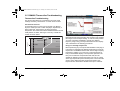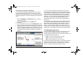
1
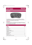
DSM400 Installation Guide.book Page 1 Tuesday, November 4, 2008 4:53 PM
DSM400
Digital Sounder
Module
Installation Guide
DSM400 Installation Guide.book Page 2 Tuesday, November 4, 2008 4:53 PM
Trademarks and registered trademarks
Autohelm, HSB, RayTech Navigator, Sail Pilot, SeaTalk and Sportpilot are UK registered trademarks of Raymarine UK Limited.
Pathfinder and Raymarine are UK registered trademarks of Raymarine Holdings Limited. 45STV, 60STV, AST, Autoadapt, Auto GST,
AutoSeastate, AutoTrim, Bidata, G-Series, HDFI, LifeTag, Marine
Intelligence, Maxiview, On Board, Raychart, Raynav, Raypilot, RayTalk, Raystar, ST40, ST60+, Seaclutter, Smart Route, Tridata and
Waypoint Navigation are trademarks of Raymarine UK Limited.
All other product names are trademarks or registered trademarks of
their respective owners.
© Raymarine UK Ltd. 2008
Document number: 87092-2
Date: November 2008
DSM400 Installation Guide.book Page 3 Tuesday, November 4, 2008 4:53 PM
Contents
Contents ..................................................... 3
Safety notices ............................................. 5
Important information.................................. 7
Introduction ...........................................................7
Intended use .........................................................7
EMC conformance ................................................7
Declaration of conformity ......................................7
WEEE Directive ....................................................7
RoHS Directive .....................................................7
Conventions..........................................................8
Warranty ...............................................................8
Handbook .............................................................8
Installation .................................................. 9
Introduction ...........................................................9
EMC installation guidelines...................................9
Cable suppression ferrites ..................................10
Planning the installation......................................12
Location of the sounder module....................12
What’s in the box ................................................13
Installing the unit.................................................13
Cable runs ..........................................................14
Power cable ..................................................15
Transducer cable ..........................................15
System and transducer connections ........ 17
Introduction .........................................................17
Unit connections .................................................17
Transducer connections .....................................18
Non-Diplexed transducer cables................... 19
Custom transducer configurations...................... 19
Ultrasonic speed/temperature transducer .......... 21
DC power connection ......................................... 21
Ground connection ............................................. 22
Power input cable ......................................... 22
Transducer cable .......................................... 22
Display connection ............................................. 23
Connecting to an E-Series display................ 23
Connecting to multiple E-Series displays ..... 24
Connecting to a G-Series system ................. 24
Maintenance and troubleshooting ............ 25
Introduction......................................................... 25
Maintenance ....................................................... 25
EMC servicing and safety guidelines............ 25
Routine checks ............................................. 26
Cleaning........................................................ 26
Resetting the system .......................................... 27
Troubleshooting.................................................. 28
Common problems and their solutions ......... 28
DSM400 Thermocline Troubleshooting .............. 29
Thermocline Troubleshooting ....................... 29
Warnings and errors ........................................... 30
Contacting Raymarine ........................................ 31
Using the website ......................................... 31
In the US....................................................... 31
Worldwide ..................................................... 32
In Europe ...................................................... 32
3
DSM400 Installation Guide.book Page 4 Tuesday, November 4, 2008 4:53 PM
Specifications ........................................... 35
General............................................................... 35
Features ............................................................. 36
4
DSM400 Installation Guide.book Page 5 Tuesday, November 4, 2008 4:53 PM
Safety notices
Warning: Product installation
This equipment must be installed and
operated in accordance with the
Raymarine instructions provided.
Failure to do so could result in poor
product performance, personal injury,
and/or damage to your boat.
Warning: High voltage
This equipment contains high voltages.
Warning: Sources of ignition
This equipment MUST NOT be installed
in hazardous/flammable atmospheres
such as an engine room.
Warning: Transducer cable
Removing the transducer cable(s) from
the unit while powered ON can cause
sparks. Only remove a transducer
cable after the unit has been powered
OFF.
DO NOT remove the covers or access
internal components unless instructed
to do so within the product handbook.
Warning: Operation
NEVER remove the DSM400 cover when
power is connected.
NEVER touch the transducer face when
the sounder is powered on.
Warning: Power supply
Make sure the boat’s power supply is set
to OFF before starting to install this
product. Unless stated otherwise only
connect or disconnect this equipment
with the power supply set to OFF.
Warning: Heavy object
The DSM400 Digital Sounder Module
weighs 27 lbs (12.25 kg). Ensure that
the chosen location for the unit is able
to support the weight.
Take care when lifting or moving the
unit.
NEVER operate the sounder with the
boat out of the water.
SWITCH OFF the sounder if divers are
likely to be within 25 ft (5 m) of the
transducer.
Caution: Mounting the unit
Due to the weight of the unit, it must be
mounted using the bolts supplied. DO
NOT use self-tapping screws as these
will not support the weight.
Caution: Service and
Maintenance
This product contains no user serviceable parts.
5
DSM400 Installation Guide.book Page 6 Tuesday, November 4, 2008 4:53 PM
6
Raymarine DSM400 Digital Sounder Module
DSM400 Installation Guide.book Page 7 Tuesday, November 4, 2008 4:53 PM
Important information
Introduction
The original Declaration of Conformity certificate may be viewed
on the relevant product page at www.raymarine.com
Your Raymarine DSM400 is a 'black box'
digital sounder module that provides full
function fishfinding and sonar capabilities
to Raymarine E-Series and G-Series
systems.
Intended use
WEEE Directive
The Waste Electrical and Electronic Equipment (WEEE)
Directive requires the recycling of waste electrical and
electronic equipment. Whilst the WEEE Directive does
not apply to some Raymarine products, we support its
policy and ask you to be aware of how to dispose of this
7-1
096
D1
The intended use for your Raymarine DSM400 Digital Sounder
Module is for leisure marine boats and workboats not covered by
International Maritime Organisation (IMO) and Safety of Life at
Sea (SOLAS) Carriage Regulations.
product.
The crossed out wheelie bin symbol, illustrated above, and
found on our products, signifies that this product should not be
disposed of in general waste or landfill.
EMC conformance
Please contact your local dealer, national distributor or
Raymarine Technical Services for information on product
disposal.
All Raymarine equipment and accessories are designed to the
best industry standards for use in the leisure marine market.
RoHS Directive
The design and manufacture of Raymarine equipment and
accessories conform to the appropriate Electromagnetic
Compatibility (EMC) standards, but correct installation is
required to ensure that performance is not compromised.
RoHS
COMPLIANT
This product uses components that comply with the
Restriction of the use of certain Hazardous
Substances (RoHS) Directive 2002/95/EC.
Declaration of conformity
Raymarine plc declare that the DSM400 Digital Sounder Module
is in compliance with the essential requirements of EMC
Directive 2004/108/EC.
7
DSM400 Installation Guide.book Page 8 Tuesday, November 4, 2008 4:53 PM
Conventions
Within this handbook the following conventions are used:
This symbol indicates a hint or tip.
This symbol indicates a note.
Warranty
To register your Raymarine DSM400 Digital Sounder Module
ownership, please take a few minutes to fill out the warranty
registration card found in the box, or visit www.raymarine.com
and register on-line.
It is important that you register your product to receive full
warranty benefits. Your unit package includes a barcode label
indicating the serial number of the unit. You should stick this
label to the warranty registration card.
Handbook
To the best of our knowledge, the information in this handbook
was correct as it went to press. However, Raymarine cannot
accept liability for any inaccuracies or omissions it may contain.
In addition, our policy of continuous product improvement may
change specifications without notice. As a result, Raymarine
cannot accept liability for any differences between the product
and the handbook.
8
Raymarine DSM400 Digital Sounder Module
DSM400 Installation Guide.book Page 9 Tuesday, November 4, 2008 4:53 PM
Chapter 1: Installation
1.1 Introduction
This chapter deals with the installation of the DSM400
Digital Sounder Module and covers the following:
•
EMC installation
guidelines
- refer to page 9
•
Planning the installation
- refer to
page 12
•
What’s in the box
- refer to
page 13
•
Installing the unit
- refer to
page 13
•
Cable runs
- refer to
page 14
•
Extending cables
- refer to
page 15
Connections to the unit are dealt with in “System and
transducer connections” on page 17.
1.2 EMC installation guidelines
All Raymarine equipment and accessories are designed
to the best industry standards for use in the recreational
marine environment.
Installation
Their design and manufacture conforms to the
appropriate Electromagnetic Compatibility (EMC)
standards, but correct installation is required to ensure
that performance is not compromised. Although every
effort has been taken to ensure that they will perform
under all conditions. It is important to understand what
factors could affect the operation of the equipment.
1
The guidelines given here describe the conditions for
optimum EMC performance, but it is recognized that it
may not be possible to meet all of these conditions in all
situations. To ensure the best possible conditions for
EMC performance within the constraints imposed by any
location, always ensure the maximum separation
possible between different items of electrical equipment.
•
Place equipment at least 5ft (1.5 m) from any
equipment transmitting or cables carrying radio
signals, e.g. VHF radios, cables and antennas. In
the case of SSB radios, the distance should be
increased to 7ft (2 m).
•
Place equipment more than 7ft (2 m) from the path
of a radar beam. A radar beam can normally be
assumed to spread 20 degrees above and below
the radiating element.
•
The equipment is supplied from a separate battery
from that used for engine start. Voltage drops below
10 V and starter motor transients can cause the
equipment to reset. This will not damage the
9
DSM400 Installation Guide.book Page 10 Tuesday, November 4, 2008 4:53 PM
equipment, but may cause the loss of some information and
may change the operating mode.
•
Cables are not cut or extended unless doing so is detailed
in the installation manual.
Remember
Where constraints on the installation prevent any of the above
recommendations:
•
Always allow the maximum separation possible between
different items of electrical equipment. This will provide the
best conditions for EMC performance for the installation.
1.3 Cable suppression ferrites
The DSM400 is supplied with a pack of suppression ferrites.
These must be fitted correctly to ensure optimum EMC performance and to comply with applicable EMC regulations.
Fit the ferrites to the cables supplied as shown overleaf.
Additional cables and ferrites
Additional cables fitted to the system will also require ferrites.
Use only ferrites of the correct type, supplied by Raymarine
authorized dealers.
Connection to other equipment
If Raymarine equipment is to be connected to other equipment
using a cable not supplied by Raymarine, a Raymarine suppression ferrite MUST always be attached to the cable in a position
near the Raymarine unit.
10
Raymarine DSM400 Digital Sounder Module
DSM400 Installation Guide.book Page 11 Tuesday, November 4, 2008 4:53 PM
Cable suppression ferrite pack installation
70 mm (2.76 in)
DSM400
Cable tie
Ferrite
Cable tie
Cable clip
Ethernet
Power
Speed/Temp
Transducer 1
Transducer 2
D11046-1
Note: Cable ties are not required for the Transducer 1 or Transducer 2 ferrites.
Installation
11
DSM400 Installation Guide.book Page 12 Tuesday, November 4, 2008 4:53 PM
1.4 Planning the installation
Warning: Product installation
The unit should be mounted where it will be:
This equipment must be installed in
accordance with the instructions contained in
this handbook. Failure to do so may result in
poor product performance, personal injury,
and/or damage to the boat.
•
protected from physical damage and excessive vibration.
•
protected from prolonged exposure to rain, salt spray and
direct sunlight.
•
well ventilated.
•
as close to the transducer as possible.
Warning: Sources of ignition
When choosing a location for the sounder module, consider the
following points to ensure reliable and trouble free operation.
This equipment must NOT be installed or used
in hazardous/flammable atmospheres such as
an engine room.
Warning: Heavy object
The DSM400 Digital Sounder Module weighs 27
lbs (12.25 kg). Ensure that the chosen location
for the unit is able to support the weight.
Take care when lifting or moving the unit.
Caution: Mounting the unit
Due to the weight of the unit, it must be
mounted using the bolts supplied. DO NOT use
self-tapping screws as these will not support
the weight.
Before installing the unit, consider the following:
•
Location of the sounder module.
•
Cable runs.
•
Transducer selection.
12
Location of the sounder module
•
Access - there must be sufficient space below the unit to
enable cable connections to the unit, avoiding tight bends.
•
Interference - the unit should be mounted far enough away
from any device that may cause interference such as
motors, generators and radio transmitters/receivers. See
“EMC installation guidelines” on page 9.
•
Magnetic compass - mount the unit at least 3 ft. (1 m)
away from a magnetic compass.
•
Vertical surface - the unit must be mounted in an upright
position.
DO NOT mount the unit:
•
in an engine room.
•
on the main console.
•
on a horizontal surface
Raymarine DSM400 Digital Sounder Module
DSM400 Installation Guide.book Page 13 Tuesday, November 4, 2008 4:53 PM
1.5 What’s in the box
1.6 Installing the unit
Unpack the unit and associated components carefully to prevent
damage. Save the box and packing in case the unit needs to be
returned for service.
Having selected a suitable location, install the unit using the
supplied hardware.
Check that all the correct system components are included as
shown in the drawing below.
To install the unit:
1. Using tape, secure the mounting template in the required
location.
DSM400
DSM
40
0m
ou
ntin
g te
mpl
ate
34
mm
(1.3
4 in)
UP
Manual
33
mm
(1.3
in)
34
mm
(1.3
4 in)
398
415
mm
mm
(15
.67
(16
.34
in)
in)
306
.5
(12 mm
.06
in)
Screw,
M6 x 60mm (x8)
Plain washer,
M6 (x8)
Spring washer,
M6 (x8)
Nut,
Self tapper screw,
M6 (x8)
No.12 (x8)
D10978-1
Not all cable glands are supplied fitted to the unit as shown
above, but will be found loose in the components bag.
Installation
D10979-1
33
mm
(1.3
0 in)
2. Drill a 9/64” pilot hole at each of the eight marked locations
on the template.
13
DSM400 Installation Guide.book Page 14 Tuesday, November 4, 2008 4:53 PM
Drill 9/64" pilot hole
in 8 positions
6
DSM
40
0m
ou
ntin
g te
mpl
ate
34
mm
(1.3
4 in)
UP
33
mm
(1.3
in)
34
mm
(1.3
4 in)
398
415
mm
mm
(15
.67
(16
.34
in)
in)
4
306
.5
(12 mm
.06
in)
33
mm
(1.3
0 in)
D10980-1
DSM
400
SOU
ND
ER
MO
DU
LE
5
Unit MUST be mounted in an upright position
4
For fiberglass mountings, countersink each of the pilot
holes to prevent damage to the gelcoat when driving in the
bolts.
D10987-1
6. Tighten the bolts to secure the unit in position.
3. Fix the mounting bolts into the eight holes.
4. Place the unit onto the mounting bolts.
5. Press the module downwards to engage the key slots in the
unit.
1.7 Cable runs
Before installing the system cables, consider the following
points:
•
14
Power, transducer and network cables need to be attached
to the unit.
Raymarine DSM400 Digital Sounder Module
DSM400 Installation Guide.book Page 15 Tuesday, November 4, 2008 4:53 PM
•
Cables should be adequately secured, protected from
physical damage, and protected from exposure to heat.
•
Avoid running cables through bilges or doorways, or close
to moving or hot objects.
•
Avoid sharp bends.
•
Use a watertight feed-through wherever a cable passes
through an exposed bulkhead or deckhead.
•
Secure cables in place using tie-wraps or lacing twine. Coil
any extra cable and tie it out of the way.
Power cable
The power cable should be run as a single length of cable from
the unit to the boat’s battery/distribution panel.
1. The figures assume a constant current of 7A,
regardless of input voltage.
2. Cable length is the distance between the power source
and the unit.
3. These wire sizes give a total drop of about 0.5 V
between the power source and the unit, achieving a
minimum voltage at the unit of 10.5 V with a fully flat
battery at 11V.
Transducer cable
Raymarine does not recommend extending the transducer
cable. However, if this is unavoidable contact your local dealer
for assistance.
Please refer to the following table to ensure that the correct
gauge of cable is used for the required cable length.
Cable length
Wire size
Feet
Metres
AWG
mm2
10
3
14
2.1
15
4.6
14
2.1
20
6
12
3.3
25
7.6
12
3.3
30
9
10
5.3
Installation
15
DSM400 Installation Guide.book Page 16 Tuesday, November 4, 2008 4:53 PM
16
Raymarine DSM400 Digital Sounder Module
DSM400 Installation Guide.book Page 17 Tuesday, November 4, 2008 4:53 PM
2
Chapter 2: System and transducer connections
2.1 Introduction
This chapter deals with connecting the DSM400 Digital
Sounder Module to the system and transducers to the
unit and covers:
•
Ultrasonic speed/depth
transducer
- refer to page 21
•
DC power connection
- refer to page 21
•
Unit connections
- refer to page 17
•
Grounding the display
- refer to page 22
•
Transducer connections
- refer to page 18
•
Connecting to a display
- refer to page 23
•
Custom transducer
configuration
- refer to page 19
2.2 Unit connections
The unit connectors are located at the base of the unit as shown below:
Speed/Temp
Ethernet
Power
POWER
Transducer 1
SPEED/TEMP
TRANSDUCER 1
Transducer 2
TRANSDUCER 2
D10981-1
System and transducer connections
17
DSM400 Installation Guide.book Page 18 Tuesday, November 4, 2008 4:53 PM
2.3 Transducer connections
WARNING: Transducer cable
Removing the transducer cable(s) from the unit while powered ON can cause sparks. Only remove a
transducer cable after the unit has been powered OFF.
The following diagram shows the layout of the transducer connections within your DSM400 Digital Sounder Module:
CUSTOM CONFIG.
Watertight bungs supplied with your unit
should be fitted to any unused connectors
TRANSDUCER 2 HIGH
2
TRANSDUCER 2 LOW
TRANSDUCER 1 HIGH
Earth/
Ground
TRANSDUCER 1 LOW
SHIELD
SHIELD
Yellow
Screen
Black
Blue
T˚ Id
Screen
G
Black
White
Orange
TRANSDUCER 1 HIGH TRANSDUCER 1 LOW
Screen + Brown
Yellow
Screen
Black
T˚ Id
Blue
G
Screen
White
Orange
Br Gr Wh Re
3
Black
Screen + Brown
GROUND
Screen + Brown
Green
White
Red
POWER
Black
Screen
4
Red
1
TRANSDUCER 2 HIGH
TRANSDUCER 2 LOW
SHIELD
SHIELD
5
Speed
Transducer
18
Depth 1
Depth 2
D10982-2
Raymarine DSM400 Digital Sounder Module
DSM400 Installation Guide.book Page 19 Tuesday, November 4, 2008 4:53 PM
The numbers within the drawing refer to the detailed illustrations within this chapter.
Note: Only one temperature wire should be connected. (To
either the speed/temperature or non-diplexed transducer
input as appropriate.)
Non-Diplexed transducer cables
Non-Diplexed transducer cables contain wires bundled as
detailed and should be connected within the sounder module as
shown in the following diagram:
:
Yellow
Screen
Black
Blue
T˚ Id
Screen
White
Orange
G
Black
Screen + Brown
1
TRANSDUCER 1 HIGH TRANSDUCER 1 LOW
SHIELD
Bundle
Function
Blue/black/shield
High frequency +/-/shield
Yellow/black-and-white/shield
Low frequency+/-/shield
Brown/white/shield
Ground/temp/ground
Orange/shield
Transducer ID/Ground
The overall screen must be connected to the unit earth bolt
using the ground spur cable supplied - refer to “Ground
connection” on page 22.
SHIELD
2.4 Custom transducer configurations
If the cable connections for the transducer you are using with
your DSM400 do not include an ‘Orange ID’ wire, you will need
to configure the sounder unit manually to match the power and
frequency of the transducer. To do this, use one of the four
override rotary switches located on the left of the sounder unit
printed circuit board (PCB).
2
CUSTOM CONFIG.
TRANSDUCER 2 HIGH
TRANSDUCER 2 LOW
TRANSDUCER 1 HIGH
D10988-1
TRANSDUCER 1 LOW
D10990-1
System and transducer connections
19
DSM400 Installation Guide.book Page 20 Tuesday, November 4, 2008 4:53 PM
It is important that when you make a manual override to the
configuration settings, make sure that you match the power and
frequency settings exactly or you may damage the transducer.
The rotary switches have the following settings:
20
High Frequency
Low Frequency
0
Override OFF (use Orange
ID)
Override OFF (use Orange
ID)
1
Disconnected (use Orange
ID cable, but channel is disconnected)
Disconnected (use Orange
ID cable, but channel is disconnected)
2
Reserved
Reserved
3
Reserved
Reserved
4
200 KHz/ 100 W
50 KHz/ 600 W
5
200 KHz/ 300 W
50 KHz/ 1 kW
6
200 KHz/ 600 W
50 KHz/ 2 kW
7
200 KHz/ 1 kW
50 KHz/ 3 kW
8
200 KHz/ 2 kW
38 KHz/ 600 W
9
185 KHz/ 100 W
38 KHz/ 1 kW
A
185 KHz/ 300 W
38 KHz/ 2 kW
B
185 KHz/ 600 W
38 KHz/ 3 kW
C
185 KHz/ 1 kW
28 KHz/ 600 W
D
185 KHz/ 2 kW
28 KHz/ 1 kW
E
Reserved
28 KHz/ 2 kW
F
Reserved
28 KHz/ 3 kW
Raymarine DSM400 Digital Sounder Module
DSM400 Installation Guide.book Page 21 Tuesday, November 4, 2008 4:53 PM
2.5 Ultrasonic speed/temperature transducer
Screen + Brown
White
Orange
3
Screen + Brown
Green
White
Red
If you are installing a separate ultrasonic speed/temperature
transducer, you should connect it to the sounder unit as shown
in the following diagram:
G
T˚ Id
Br Gr Wh Re
2.6 DC power connection
WARNING: Power supply
Make sure the boat’s power supply is set to OFF
before starting to install this product. Unless
stated otherwise only connect or disconnect
this equipment with the power supply set to
OFF.
Your DSM400 Digital Sounder Module is intended for use on DC
power systems rated from 10.7 V to 32V.
The power connection to the sounder unit should be made at
either the output of the battery isolator switch or at a DC power
distribution panel. Power should be fed directly to the sounder
unit on a dedicated cable system and protected by a 5 amp
thermal circuit breaker or quick-blow 10 amp fuse installed in the
red ((positive) wire. The thermal circuit breaker or fuse should be
connected as close to the power connection as possible.
There is no power switch on your sounder unit. The unit is
powered when the power cord is attached to the boat’s power
Locate the unit so that the power cord can be accessed and
removed easily if necessary. If this is not possible, Raymarine
strongly recommend that an ON/OFF switch is installed in the
power cord where it can be easily accessed.
Red
Positive
White
Temperature
Green
Speed signal
Screen and brown
Negative
System and transducer connections
The DC power connections are shown in the following drawing:
21
DSM400 Installation Guide.book Page 22 Tuesday, November 4, 2008 4:53 PM
2.7 Ground connection
Power input cable
Black
Screen
Red
4
POWER
GROUND
Br Wh Gr
Your DSM400 Digital Sounder Module is designed for use on
boat’s with a ‘negative’ ground system and is not intended for
use on boat’s with a ‘positive’ ground system.
It is important that an effective RF ground is connected to the
system. A single ground point should be used for all equipment.
You can ground the sounder unit by connecting the drain wire
(shield) of the power input cable to the boat’s RF ground.
If you need to extend the wire, the extension wire should be an 8
mm braid or AWG 10 multi-stranded cable. If your boat does not
have and RF system, connect the drain wire to the negative
battery terminal.
D10992-2
The boat’s DC power system should be either:
•
Negative ground, with the negative battery terminal
connected to the boat’s ground, or,
•
Floating, with neither battery terminal connected to the
boat’s ground.
Transducer cable
Terminal
Function
Color
+
Battery positive
Red
Ground
Shield (drain wire)
No insulation
-
Battery negative
Black
22
To ensure an efficient ground for the transducer cable(s) you
should carry out the following:
1. Gather the external shield wires from the transducer cable(s)
and twist the free ends together.
2. Insert these twisted ends into the connector of the ground
spur.
3. Using a suitable tool, crimp the twisted ends into the ground
spur connector.
Raymarine DSM400 Digital Sounder Module
DSM400 Installation Guide.book Page 23 Tuesday, November 4, 2008 4:53 PM
4. Attach the ground spur to the ground screw on the body of
the sounder unit.
Connections for both E-Series and G-Series displays are shown
in the following diagrams:
Connecting to an E-Series display
DSM400
GPS
antenna
E series display
PAGE
ACTIVE
WPTS
MOB
DATA
MENU
OUT
RANGE
IN
OK
CANCEL
Power
D10983-1
D10994-1
2.8 Display connection
Your DSM400 Digital Sounder Module can be connected to
either E-Series or G-Series display units.
How you configure the sounder module depends on the type of
display to which it is going to be connected. Full details will be
found in the relevant documentation for your display.
System and transducer connections
23
DSM400 Installation Guide.book Page 24 Tuesday, November 4, 2008 4:53 PM
Connecting to multiple E-Series displays
Connecting to a G-Series system
GPS
antenna
DSM400
E series display
GPM 400 (Central processor)
PAGE
ACTIVE
WPTS
MOB
DATA
MENU
SeaTalkhs switch
OUT
RANGE
IN
OK
DSM digital sounder
CANCEL
C/lines for plugs/sockets
SeaTalkhs
Power
SeaTalkhs
E series display
Transducer
PAGE
ACTIVE
WPTS
MOB
SeaTalkhs switch
DATA
DXXXXX-1
MENU
OUT
RANGE
IN
OK
SeaTalkhs
SeaTalkhs
CANCEL
SeaTalkhs
SeaTalkhs
D10984-1
24
Raymarine DSM400 Digital Sounder Module
DSM400 Installation Guide.book Page 25 Tuesday, November 4, 2008 4:53 PM
Chapter 3: Maintenance and troubleshooting
3.1 Introduction
3.2 Maintenance
This chapter deals with maintenance and
troubleshooting for the DSM400 Digital Sounder Module,
and covers the following:
•
Maintenance
- refer to page 25
•
Resetting the system
- refer to page 27
•
Troubleshooting
- refer to page 28
•
Warnings and errors
- refer to page 30
•
Thermocline troubleshooting
- refer to page 29
•
Contacting Raymarine
- refer to page 31
Adjustments to this equipment requires specialized
service procedures and tools only available to qualified
service technicians. There are no user serviceable parts
or adjustments.
Maintenance and troubleshooting
3
WARNING: High voltage
This equipment contains high voltages.
Unless otherwise instructed in this
handbook DO NOT remove the covers or
access internal components.
CAUTION: Service and Maintenance
This product contains no user
serviceable parts.
EMC servicing and safety guidelines
•
Raymarine equipment should be serviced only by
authorized Raymarine service technicians. They will
ensure that service procedures and replacement
parts used will not affect performance. Raymarine
products do not contain any user serviceable parts.
•
Some products generate high voltages. Never
handle cables or connectors when power is being
supplied to the equipment.
•
When powered all electrical equipment produces
electromagnetic fields. These can cause adjacent
items of electrical equipment to interact with one
another, with consequent adverse effects on
operation. To minimize these effects and enable
best possible performance from the equipment
guidelines are given in the installation instructions,
to ensure minimum interaction between different
25
DSM400 Installation Guide.book Page 26 Tuesday, November 4, 2008 4:53 PM
items of equipment, i.e. ensure optimum Electromagnetic
Compatibility (EMC).
prevent the build-up of sea growth, coat the transducer with a
thin layer of paint.
•
Always report any EMC related problem to a Raymarine
dealer. Such information is used to improve quality
standards.
Use only water-based antifouling paint, or a water-based paint
specifically designed for transducers. Apply the paint with a
brush.
•
In some instances it may not be possible to prevent the
equipment from being affected by external influences. In
general this will not damage the equipment but can lead to
spurious resetting action, or may result in momentary faulty
operation
If the transducer becomes fouled or stops working because of
sea growth or sand, use a stiff brush to clean it. The surface can
also be sanded with a fine-grit wet or dry sandpaper (#320 grade
or finer), but this will affect the performance of the unit when the
boat is moving at higher speeds.
Routine checks
The DSM400 Digital Sounder Module is a sealed unit.
Maintenance is therefore limited to the following periodic checks:
The paddle wheel mechanism may become jammed by dirt, grit
or barnacles. Work the contaminant out of the mechanism, then
clean the unit with soap and water or IPA.
•
Examine all of the cables for signs of damage, such as
chafing, cuts or nicks.
Cleaning the hull
•
Check that all cable connectors are firmly attached.
Cleaning
Take care when cleaning the outside of the hull near the
transducer as harsh cleaning solvents such as acetone may
damage the transducer.
Cleaning the unit
The sounder module is a sealed unit and does not require
regular cleaning. If it necessary to clean the unit, follow these
basic procedures:
•
Ensure the power is set to OFF.
•
Wipe the module using a damp cloth.
•
If necessary, use isopropyl alcohol (IPA) or a mild detergent
to remove grease marks.
Cleaning the transducer
Sea growth can collect quickly on the bottom of the transducer
which can reduce its performance in just a few weeks. To
26
Raymarine DSM400 Digital Sounder Module
DSM400 Installation Guide.book Page 27 Tuesday, November 4, 2008 4:53 PM
3.3 Resetting the system
Using the reset function will return your DSM400 Digital Sounder
Unit to its factory default values. The reset function also clears
any sonar depth offset and speed and temperature calibrations
that have been set.
To perform a factory reset:
1. On the display, make the Fishfinder window active.
2.
3.
4.
5.
6.
7.
Press Menu.
Select Fishfinder Setup.
Select DSM Settings.
Select DSM Reset.
The message Reset DSM? appears.
To confirm the reset, select soft key YES, or press OK.
DSM powers OFF and ON, the LED will go from blinking
green to solid orange (1 sec.)., the System Data Alarm will
sound showing that connection to the DSM is lost.
8. Press the ACKNOWLEDGE soft key.
After approximately 10 seconds the DSM will re-acquire
data.
9. To complete the reset, read the warning and press OK.
To cancel the reset, either:
Before pressing YES (Step 7 above), either, press NO softkey,
or, CLEAR button. The screen changes to show the Fishfinder
DSM Settings.
Press CANCEL three times to return to the fishfinder
application.
Maintenance and troubleshooting
27
DSM400 Installation Guide.book Page 28 Tuesday, November 4, 2008 4:53 PM
3.4 Troubleshooting
All Raymarine products are, prior to packing and shipping,
subject to comprehensive test and quality assurance programs.
However, if the unit develops a fault please refer to the following
table to identify the most likely cause and the corrective action
required to restore normal operation.
If there is still a problem after referring to the table, contact your
local Raymarine dealer, national service agent or Raymarine
Technical Services for further advice. Always quote the product
serial number which can be found on the back of the unit.
Common problems and their solutions
Problem
Solution
Display freezes
1. Check that the scroll speed is not set to zero.
2. Check the transducer cable for damage. If damaged the cable and transducer must be replaced as a
unit.
Sounder does not display fish
1. Fish arches are not displayed if the boat has stopped - fish will appear on the display as a straight line.
2. Ensure the transducer is within 10 degrees of vertical.
3. Check that the gain is not set too low.
Sounder does not see bottom or fish
1.
2.
3.
4.
Sounder displays a lot of background noise
1. Check that the gain is not set too high.
2. Check that the transducer is mounted correctly and is clean.
Sounder temperature readings are wrong
If necessary, adjust the TEMP CALIBRATE parameter.
Sonar display is unreliable at high boat speeds
Turbulence around the transducer may be confusing the unit. Check the transducer location.
28
Check that the gain is not set too low.
Ensure the transducer is within 10 degrees of vertical.
Check that the transducer face is not covered or fouled - If necessary clean the transducer.
Check the voltage from the power source. If it is too low it can affect the transmitting power of the
sounder.
Raymarine DSM400 Digital Sounder Module
DSM400 Installation Guide.book Page 29 Tuesday, November 4, 2008 4:53 PM
3.5 DSM400 Thermocline Troubleshooting
Thermocline
A thermocline looks like a
thick speckled band on the
display. The debris and
marine life found in the
thermocline cause the sonar
to mis-interpret it as the
bottom, giving inaccurate
depth readings.
Thermocline Troubleshooting
This section describes how to troubleshoot incorrect depth
readings caused by “thermoclines” in certain areas of water.
Actual Depth
(2000 feet)
((((
Mixed Layer
((
Thermocline
D11138_1
Depth (feet)
1000
Deep Water
Temperature
Maintenance and troubleshooting
D11138_1
2000
Actual Bottom
This is the actual bottom
depth (2289 ft).
False Depth Reading
The thermocline causes an
incorrect depth reading.
This problem occurs when fishfinder sonars (including the
DSM400) interpret the thermocline as the bottom of the seabed,
returning an incorrect depth reading. To overcome this problem,
you must configure the DSM400 to operate in a different
frequency range, using your Raymarine Multi-Function Display.
This is described in the following procedures.
0
Depth Detected by
Sonar (1100 feet)
Zoomed Area
The scale for this part of the
display is not relevant in
this particular example.
D11152_1
Thermocline Overview
In temperature terms, oceans can be thought of in different
layers; a mixed layer and a colder deep layer, separated by a
thermocline layer, where there is an abrupt change in
temperature. The thermocline attracts additional marine life and
small particles of debris, reducing the accuracy of fishfinder
sonars, as shown below:
Using Low and High Frequencies
Before performing any of the procedures detailed on this page, it
is important to understand the difference between low and high
frequencies. The DSM400 features both low and high frequency
transducers, enabling you to view low or high frequencies (or
both) in the fishfinder display. Low frequencies (less than 100
Khz) scan a wide area and penetrate water well, and are
suitable for displaying a large area below your boat, or in deep
water. High frequencies (100 to 200 Khz) scan a narrow area but
produce more detail, especially at high boat speeds. High
frequencies are well-suited to shallow waters up to 1000 feet.
29
DSM400 Installation Guide.book Page 30 Tuesday, November 4, 2008 4:53 PM
Achieving Accurate Sonar Readings
If you are using the DSM400 at depths of less than 100 feet,
thermoclines are always penetrated correctly by the sonar,
providing accurate depth readings. If you are using the DSM400
at depths greater than 100 feet, and displaying low frequencies
only:
1. Press the RANGE IN or RANGE OUT button to open the
Range Adjust toolbar.
2. Toggle the RANGE softkey to the MAN option.
3. Press OK.
4. In the main fishfinder view, press the RANGE SHIFT softkey.
5. Using the rotary control, adjust the range so that the true sea
bottom and the thermocline return are displayed. Continue to
adjust the range until the thermocline is shifted off the top of
the screen, while the true bottom remains on the screen. The
correct depth is then displayed, as shown in the following
diagram:
Thermocline
Here, the bottom of the
thermocline can still be
seen, as it was range-shifted
to the top of the display.
30
3.6 Warnings and errors
The status Light Emitting Diode (LED) on the top casing of the
sounder module provides information on the status of the
sounder module and notifies you of any problems within the unit.
The LED blinks the following colors:
Actual Bottom
This is the actual bottom
depth (2289 ft).
True Depth Reading
The DSM400 sonar has
penetrated the thermocline,
and is now displaying the
correct depth reading.
If you are using a combination of the low and high frequencies
(for example, using the split display function and/or one of the
dual-frequency preset modes), you may be able to see the
bottom correctly by range-shifting the low frequency part of the
display. If the correct bottom depth is not returned, you may
need to switch to low frequencies only, and then use the Range
Shift function to penetrate the thermocline, as described above.
•
Green - shows the unit is operating normally.
•
Amber - warns of a problem in the unit.
•
Red - shows that there is an error in the unit.
The number of times the LED ‘blinks’ is a code which represents
the errors or warnings shown in the table below. If there are
multiple warnings or errors, the codes are given in a sequence
with a 1.5 second pause between sequence strings.
D11151_1
Zoomed Area
The scale for this part of the
display is not relevant in
this particular example.
If you are using the DSM400 at depths greater than 100 feet,
and displaying high frequencies only, the Range Shift function
has no impact, as the high frequencies mean that it is less likely
that a thermocline will be detected as a bottom in any range.
However, in the event that a thermocline is mis-interpreted as
the bottom, you must adjust the fishfinder display to show low
frequencies only, and then use the Range Shift function to
penetrate the thermocline. This procedure is described in the
steps above.
Raymarine DSM400 Digital Sounder Module
DSM400 Installation Guide.book Page 31 Tuesday, November 4, 2008 4:53 PM
For example, if the transducer sense fails and the network is not
detected, the LED blinks amber once, pauses 1.5 seconds,
blinks amber twice 0.5 seconds apart, pauses 1.5 seconds and
then repeats the sequence until the problems are resolved or up
to 10 minutes elapse.
No. of
blinks
Color
Warning/error
Cleared
every 10
mins
* After 30 seconds of no network activity, the
sounder unit enters Standby mode; No sonar pings
are emitted and no warnings or errors are output on
the Status LED. Instead the LED will blink GREEN
once every 10 seconds.
3.7 Contacting Raymarine
Using the website
Amber
Solid
DSM has rebooted
No
Amber
1
Transducer sense failure
No
Amber
2
Network not detected *
No
Click on the region that you are located in and go to the
Customer Support page for links to:
Amber
3
High temperature warning
Yes
•
Amber
4
Contact Raymarine
Finding the location of the nearest factory service and
authorized dealer for your area.
•
Register Raymarine products.
Amber
5
Contact Raymarine
•
Accessing handbooks in Adobe Acrobat TM format.
Amber
6
Contact Raymarine
•
Downloading software updates.
Accessing the Raymarine solution database.
For the latest information on Raymarine products visit the
website at www.raymarine.com.
Amber
7
Contact Raymarine
•
Amber
8
Contact Raymarine
Red
1
Contact Raymarine
Yes
Click Find Answers to use the searchable solution database, or
click Ask Raymarine to submit a question to Raymarine
technical support staff. A reply will be sent by e-mail.
Red
2
Check Voltage Supply
Yes
Red
3
Contact Raymarine
Parts and accessories
Red
4
Contact Raymarine
Red
5
Contact Raymarine
Many Raymarine parts and accessories can be obtained from
your local authorized Raymarine dealer.
Maintenance and troubleshooting
In the US
31
DSM400 Installation Guide.book Page 32 Tuesday, November 4, 2008 4:53 PM
However, if you are not able to obtain your requirements from
the dealer, contact Raymarine Technical Services at:
1-603-881-5200 ext. 2333
Technical Service is available Monday through Friday 4.00AM to
6.00PM Eastern Time.
All products returned to the Repair Center are registered upon
receipt. Should you wish to enquire about the repair status of the
unit, contact the Product Repair Center at:
1-603-881-5200 ext 2118
Please have the unit serial number ready when you call. We will
do everything possible to make the repair and return your unit as
quickly as possible.
Please have the Raymarine item or part number ready when
calling if placing an order. If you are not sure which item is
appropriate for your unit, you should contact the Technical
Support Department to verify your requirements.
Worldwide
Technical Support
Please contact the authorized dealer in the relevant country as
listed on the website at www.raymarine.com
For technical support, call:
1-603-881-5200 ext 2444
Raymarine Technical Support Specialists are available to
answer questions about installing, operating and troubleshooting
all Raymarine products.
Product repair and service
In the unlikely event that your Raymarine unit should develop a
problem, please contact your authorized Raymarine dealer for
assistance. The dealer is best equipped to handle your service
requirements and can offer timesaving help in getting the
equipment back into normal operation.
In the event that repairs cannot be obtained locally, product
service may also be obtained by returning the unit to:
Raymarine Inc.
Product Repair Center
21 Manchester Street
Merrimack, NH03054-44821
The Product Repair Center is open Monday through Friday 8.15
AM to 5.00 PM Eastern Time.
32
In Europe
In Europe, Raymarine support, service and accessories may be
obtained from your authorized dealer or by contacting:
Raymarine plc
Anchorage Park
Portsmouth
Hampshire
England
PO3 5TD
Tel: +44 (0) 23 9269 3611
Fax: +44 (0) 23 9269 4642
Technical Support
Raymarine Technical Services Department handles enquiries
concerning installation, operation, fault diagnosis and repair.
To contact the Technical Helpdesk:
Tel; +44 (0) 23 9271 4713
Raymarine DSM400 Digital Sounder Module
DSM400 Installation Guide.book Page 33 Tuesday, November 4, 2008 4:53 PM
Fax: +44 (0) 23 9266 1228
Parts and accessories
Raymarine parts and accessory items are available through your
authorized Raymarine dealer. Please refer to the lists of
component part numbers and optional accessories in the
Installation chapter of this handbook and have the numbers
ready when speaking with your dealer.
If you are uncertain about what item to choose for your
Raymarine unit, please contact the Customer Services
Department prior to placing an order.
Maintenance and troubleshooting
33
DSM400 Installation Guide.book Page 34 Tuesday, November 4, 2008 4:53 PM
34
Raymarine DSM400 Digital Sounder Module
DSM400 Installation Guide.book Page 35 Tuesday, November 4, 2008 4:53 PM
Appendix A: Specifications
General
Approvals
CE - conforms to
2004/108/EC (EMC)
EN60945:2002
Size
16.36” x 12.07” x 4.92”
(415.5 x 306.6 x 125 mm)
Weight
27 lbs (12.25 kg)
Mounting
Eight keyholed mounting tabs, mounting bolts
Mount below decks, but not in engine compartment
Power
Voltage
Current
Fuse
Environmental
Waterproofing
Operating range
Storage range
Humidity
Connections
12 or 24 V DC - nominal
10.7 - 32 V - absolute range
8 A peak (pinging), 0.5 A idle
5A
Splash proof enclosure
-10oC to + 50oC
-20oC to +70oC
up to 95% @ 35oC non-condensing
Power
2 x depth transducer 1
2 x depth transducer 2
Speed/temperature transducer
RJ-45 SeaTalk HS
35
DSM400 Installation Guide.book Page 36 Tuesday, November 4, 2008 4:53 PM
Features
Output power
selected manually or automatically up to 2 KW RMS @ 185 KHz/200KHz
selected manually or automatically up to 3 KW @ 50/38/28 KHz
(depending upon connected transducers)
Frequency
28/ 38/ 50/ 185/ 200 KHz
Pulse length
100 μ sec. up 4 msec.
Maximum transmit rate
1580 pulses/min. @ 50’ range
Gain
Auto or manual
Range scales
36 (at 10,000ft/3 km using 28/38 KHz transponder of 3 kW)
Range control
Auto, manual, range shift, dual range
Zoom size
x2, x3, x4, xR (User selectable)
A-Scope
Yes
Bottom lock
Yes
White line
Yes
Background color options
Classic-blue, classic-black, classic-white, sunburst, greyscale, copper, night vision
Scroll speed
Selectable (0-100%)
Variable range marker
Yes
Alarms
Anchor, arrival, battery, deep depth, MOB, off track, fish, shallow depth, temperature
36
Raymarine DSM400 Digital Sounder Module
DSM400 Installation Guide.book Page 37 Tuesday, November 4, 2008 4:53 PM
DSM400 Installation Guide.book Page 38 Tuesday, November 4, 2008 4:53 PM
Raymarine plc
Anchorage Park, Portsmouth,
Hampshire PO3 5TD,
United Kingdom.
Raymarine Inc.
21 Manchester Street, Merrimack,
New Hampshire 03054-4801,
USA.
Tel: +44 (0) 23 9269 3611
Fax: +44 (0) 23 9269 4642
www.raymarine.com
Tel: +1 603.881.5200
Fax: +1 603.864.4756
www.raymarine.com
87092-1 Raymarine A5 Landscape Special Cover_Back.eps