1
Technical Data
1
Protective Devices
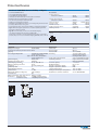
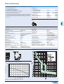
Residual Current Devices - General Data
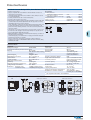
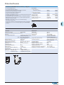
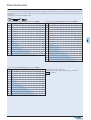
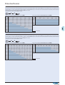
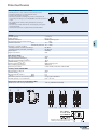
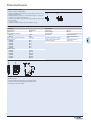
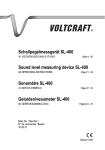
Short description of the most important RCD types:
Symbol
Description
Eaton/Moeller standard. Suitable for outdoor installation (distribution boxes for outdoor installation and building sites) up to -25° C.
Conditionally surge-current proof (>250 A, 8/20 µs) for general application.
RCD sensitive to pulsating DC for application where residual pulsating DC may occur. Non-selective, instantaneous. Protects only against special forms of residual pulsating DC which have not
been smoothed.
Type B: All-current sensitive RCD switchgear for applications where DC fault currents may occur.
Non-selective, non-delayed. Protection against all kinds of fault currents.
Type B+: All-current sensitive RCD switchgear for applications where DC fault currents may occur.
Non-selective, non-delayed. Protection against all kinds of fault currents. Also meets the requirements of the VDE 0664-400 standard (formerly known as VDE V 0664-110) and therefore provides
enhanced fire safety.
G
ÖVE E 8601
S
RCD of type G (min 10 ms time delay) surge current-proof up to 3 kA. For system components
where protection against unwanted tripping is compulsory to avoid personal injury and damage
to property (§ 12.1.6 of ÖVE/ÖNORM E 8001-1). Also for systems involving long lines and high line
capacity. Some versions are sensitive to pulsating DC. Some versions are available in all-current
sensitive design.
RCD of type S (selective, min 40 ms time delay) surge current-proof up to 5 kA. Mainly used as
main switch according to ÖVE/ÖNORM E 8001-1 § 12.1.5, as well as in combination with surge
arresters.This is the only RCD suitable for series connection with other types if the rated tripping
current of the downstream RCD does not exceed one third of the rated tripping current of the
device of type S. Some versions are sensitive to pulsating DC. Some versions are available in allcurrent sensitive design.
"X-ray-proof", for avoiding unwanted tripping caused by x-ray devices.
“röntgenfest”
"umrichterfest"
"Frequency converter-proof", for avoiding unwanted tripping caused by frequency converters,
speed-controlled drives, etc.
Integrated overload protection. Calculating and rating of the back-up temperature fuse to avoid
overload on the RCD is not required. Overload fuse = short circuit back-up fuse.
Press service key when putting the device into operation, and subsequently approximately once
per year. Pressing the key once per month is not required any more and can be omitted unless
shorter testing intervals are required under any applicable regulations (e.g. on building sites).
2
Protective Devices
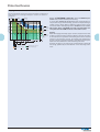
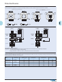
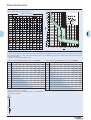
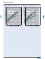
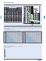
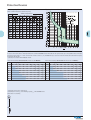
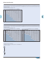
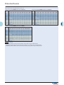
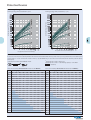
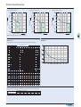
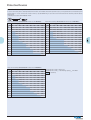
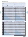
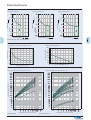
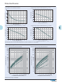
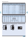
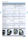
Tripping Characteristics (IEC/EN 61008)
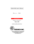
Tripping characteristics, tripping time range and selectivity of instantaneous,
surge current-proof "G" and surge current-proof - selective "S" residual current devices.
§ 6.1.1 of ÖVE/ÖNORM E 8001-1/A1 deals with additional protection and provides essentially the following:
In circuits with sockets up to 16 A with fault current/residual current protection by protective earthing, protective multiple earthing or
residual current devices (RCDs), additional residual current protection devices with a rated tripping current of 0.03 A must be installed.
This means when using RCDs for fault current/residual current protection two RCDs must be connected in series.
Tripping time t
surge current.proof - selective
surge currentproof
Testing:
RCDs with tripping time delay (Types -G and -S) may be function tested with conventional testing equipment which must be set according
to the instructions for operation of the testing device. Due to reasons
inherent in the measuring process, the tripping time determined in
this way may be longer than expected in accordance with the specifications of the manufacturer of the measuring instrument.
However, the device is ok if the result of measurement is within the
time range specified by the manufacturer of the measuring instrument.
conditionally
surge currentproof
Residual tripping current
Tripping time range limit values
Tripping time range type S
Tripping time range non-delayed
Tripping time range type G
Area of unwanted tripping
3
Protective Devices
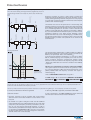
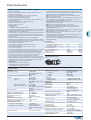
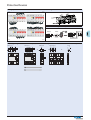
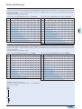
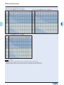
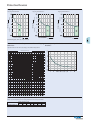
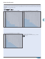
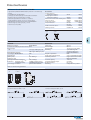
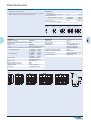
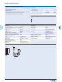
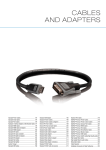
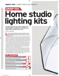
Hints for the application of our frequency converter-proof RCDs:
Due to the currents flowing off through the filters (designated IF), the sum of
currents through the RCD is not exactly zero, which causes unwanted tripping.
Frequency converters are used in a wide variety of systems and
equipment requiring variable speed, such as lifts, escalators, conveyor belts, and large washing machines. Using them for such purposes
in circuits with conventional residual current devices causes frequent
problems with unwanted tripping.
Motor
Screened motor line
The technical root cause of this phenomenon is the following: Fast
switching operations involving high voltages cause high interference
levels which propagate through the lines on the one hand, and in the
form of interfering radiation on the other. In order to eliminate this
problem, a mains-side filter (also referred to as input filter or EMC-filter) is connected between the RCD and frequency converter. The antiinterference capacitors in the filters produce discharge currents
against earth which may cause unwanted tripping of the RCD due to
the apparent residual currents. Connecting a filter on the output side
between frequency converter and 3-phase AC motor results in the
same behaviour.
Motor
Mains side filter
Frequency
converter
Frequency
converter
Mains-side filter
Mains-side filter
RCD
RCD
Mains
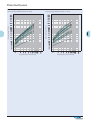
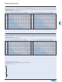
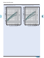
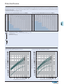
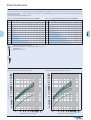
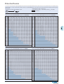
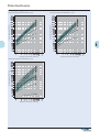
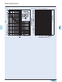
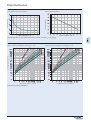
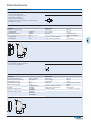
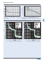
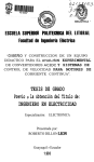
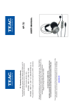
Tripping characteristic
This sample tripping characteristic of a 100 mA RCD and a 300 mA
RCD shows the following: In the frequency range around 50 Hz, the
RCDs trip as required (50 - 100 % of the indicated IΔn).
In the range shown hatched in the diagram, i. e. from approx. 100 to
300 Hz, unwanted tripping occurs frequently due to the use of frequency converters. Frequency converter-proof residual current
devices are much less sensitive in this frequency range than in the 50
- 60 Hz range, which leads to an enormous increase in the reliability
of systems.
Therefore, we recommend to use frequency converter-proof RCDs!
These special residual current devices can be recognised by an extension of the type designation ("-U"). They meet the requirements of compatibility between RCDs and frequency converters with respect to
unwanted tripping.
Frequency converter
interference range
(approx. 100 - 300 Hz)
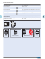
These are NOT AC/DC-sensitive RCDs of type B !!!
Our RCDs of type "-U" are characterised by SENSITIVITY TO RESIDUAL
PULSATING DC
and SELECTIVITY S or SHORT-TIME DELAY G .
Protective Measures
The following rules for the application of RCDs of type" -U" are only applicable in those cases where an RCD of type "-B" is not explicitly demanded in the
instructions of the manufacturer of the frequency converter.
How can you make sure that the required protective measures are in place when using RCDs type “-U” and frequency converters in one system?
In Austria, the ÖVE Decision EN 219 is applicable.
In Germany, VDE 0100 is applicable, in Switzerland SEV 1000.
Under this standard
In case of application in any other country than those mentioned
take into account national rules and recommendations.
• frequency converters must be equipped with current limiting
devices in order to ensure disconnection in cause of faults or overload, and
• the installer of a system is obliged to make sure that additional
equipotential bonding is provided (additional inclusion of all metal
components, such as frequency converters, mains filters, motor filters, etc. into the existing equipotential bonding), in order to
ensure that the permissible touch voltage of 50 V AC or 120 V DC is
not exceeded. (In ÖVE/ÖNORM E 8001-1 the term "touch voltage"
has been omitted. There is only a fault voltage limit of 65 V AC or
120 V DC which must not be exceeded).
4
Protective Devices
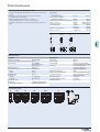
Residual Current Devices PFIM
• Type -G/A: Additionally protects against special forms of residual pulsating
DC which have not been smoothed.
Special types for X-ray application PFIM-...-R
• Type -R: To aviod unwanted tripping due to X-ray devices.
• Type -S: Selective residual current device sensitive to AC, type -S.
Compulsory for systems with surge arresters downstream of the RCD
(ÖVE/ÖNORM E 8001-1 § 12.1.5).
• Type -S/A: Additionally protects against special forms of residual pulsating
pulsating DC which have not been smoothed.
• Type -U: Suitable for speed-controlled drives with frequency converters in
household, trade, and industry.
Unwanted tripping is avoided thanks to a tripping characteristic designed
particularly for frequency converters.
See also explanation “Frequency Converter-Proof RCDs - What for?”
Application according to ÖVE/ÖNORM E 8001-1 and Decision EN 219 (1989),
VDE 0100, SEV 1000.
Accessories:
Auxiliary switch for
subsequent installation to the left
Z-HK
248432
Tripping signal contact for
subsequent installation to the right
Z-NHK
248434
Remote control and
automatic switching device
Z-FW/LP
248296
Compact enclosure
KLV-TC-2
276240
KLV-TC-4
276241
Sealing cover set
Z-RC/AK-2TE
285385
Z-RC/AK-4TE
101062
Switching interlock
IS/SPE-1TE
101911
• Residual current devices
• Shape compatible with and suitable for standard busbar connection to
other devices of the P-series
• Twin-purpose terminal (lift/open-mouthed) above and below
• Busbar positioning optionally above or below
• Free terminal space despite installed busbar
• Universal tripping signal switch, also suitable for PLS., PKN., Z-A. can be
mounted subsequently
• Auxiliary switch Z-HK can be mounted subsequently
• Contact position indicator red - green
• Delayed types suitable for being used with standard fluorescent tubes with
or without electronical ballast (30mA-RCD: 30 units per phase conductor,
100mA-RCD: 90 units per phase conductor)
Notes: Depending of the fluorescent lamp ballast manufacturer partly more
possible. Symmetrical allocation of the fluorescent lamp ballasts on all
phases favourably. Shifting references of the fluorescent lamp ballast manufacturer consider.
• The device functions irrespective of the position of installation
• Tripping is line voltage-independent. Consequently, the RCD is suitable for
“fault current/residual current protection” and “additional protection” within the the meaning of the applicable installation rules
• Mains connection at either side
• The 4-pole device can also be used for 3-pole connection.
For this purpose use terminals 1-2, 3-4, and 5-6 (+ cable link).
• The 4-pole device can also be used for 2-pole connection.
For this purpose use terminals 5-6 and N-N.
• The test key “T” must be pressed every month. The system operator must
be informed of this obligation and his responsibility in a way that can be
proven (self-adhesive RCD-label enclosed)
• Pressing the test key “T” serves the only purpose of function testing the
residual current device (RCD). This test does not make earthing resistance
measurement (RE), or proper checking of the earth conductor condition
redundant, which must be performed separately.
• Type -A: Protects against special forms of residual pulsating DC which
have have not been smoothed
• Type -G: High reliability against unwanted tripping. Compulsory for any circuit where personal injury or damage to property may occur in case of
unwanted tripping (ÖVE/ÖNORM E 8001-1 § 12.1.6).
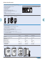
Connection diagrams
2-pole
4-pole
1 3 5 N
T
2 4 6 N
Technical Data
Electrical
Design according to
Mechanical
Frame size
Device height
Device width
IEC/EN 61008
Type G acc. to ÖVE E 8601
Current test marks as printed onto the device
Tripping
instantaneous
Type G, R
10 ms delay
Type S
40 ms delay with selective disconnecting
function
Type U (only 30 mA)
10 ms delay
Type U (without 30 mA)
40 ms delay with selective disconnecting
function
Rated voltage Un
230/400 V, 50 Hz
Rated tripping current IΔn
10, 30, 100, 300, 500 mA
Sensitivity
AC and pulsating DC
Rated insulation voltage Ui
440 V
Rated impulse withstand voltage Uimp 4 kV
Rated short circuit strength Inc
10 kA
Maximum back-up fuse
Short circuit
In = 16-63 A
63 A gG/gL
In = 80 A
80 A gG/gL
In = 100 A
100 A gG/gL
Type PFIM-X:
In = 40A
63 A gG/gL
In = 63A
63 A gG/gL
Rated breaking capacity Im or
Rated fault breaking capacity IΔm
In = 16-40 A
500 A
In = 63 A
630 A
In = 80 A
800 A
In = 100 A
1,000 A
Voltage range of test button 2-pole
184 - 250 V~
4-pole
184 - 440 V~
Endurance
electrical comp.
≥ 4,000 operating cycles
mechanical comp.
≥ 20,000 operating cycles
Mounting
Degree of protection, built-in
Deg. of prot. in moisture-proof encl.
Upper and lower terminals
Terminal protection
Terminal capacity
Busbar thickness
Tripping temperature
Storage- and transport temperature
Resistance to climatic conditions
5
45 mm
80 mm
35 mm (2MU),
70 mm (4MU)
quick fastening with
2 lock-in positions on
DIN rail IEC/EN 60715
IP40
IP54
open mouthed/lift terminals
finger and hand touch safe,
BGV A3, ÖVE-EN 6
1.5 - 35 mm2 single wire
2 x 16 mm2 multi wire
0.8 - 2 mm
-25°C to +40°C
-35°C to +60°C
25-55°C/90-95% relative
humidity acc. to IEC 60068-2
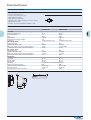
Protective Devices
RCD PFIM in a Three-Phase AC Network without Neutral Conductor
Dimensions (mm)
2P
5,5
4P
80
30,5
4,5
L1
L2
L3
L1
L2
L3
The N-terminal must be connected by a cable link
with the phase L2 (or L1), so that the test loop is
supplied with current and the RCD is tested correctly.
45
80
10,5
35
44
70
60
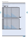
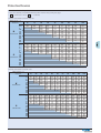
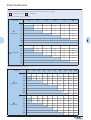
Influence of the ambient temperature to the maximum continuous current (A)
Ambient temperature
40°
45°
50°
55°
60°
16A
2p
16
14
11
9
– *)
4p
16
14
11
9
–
25A
2p
25
21
18
14
–
4p
25
22
19
16
–
40A
2p
40
37
33
30
26
4p
40
37
34
31
27
63A
2p
63
59
55
50
45
4p
63
59
55
50
45
80A
2p
80
76
72
68
64
4p
80
76
72
68
64
100A
2p
100
95
90
85
80
Annotation: It has to be ensured that the values in the table are not exceeded and the back-up fuse/thermal protection works properly
*) not applicable
6
4p
100
95
90
85
80
Protective Devices
Residual Current Devices PF7
• Type -G/A: Additionally protects against special forms of residual pulsating
DC which have not been smoothed.
Special types for X-ray application PF7-...-R
• Type -S: Selective residual current device sensitive to AC, type -S.
Compulsory for systems with surge arresters downstream of the RCD
(ÖVE/ÖNORM E 8001-1 § 12.1.5).
• Type -S/A: Additionally protects against special forms of residual pulsating
pulsating DC which have not been smoothed.
• Residual current devices
• Shape compatible with and suitable for standard busbar connection to
other devices of the P-series
• Twin-purpose terminal (lift/open-mouthed) above and below
• Busbar positioning optionally above or below
• Free terminal space despite installed busbar
• Universal tripping signal switch, also suitable for PL., PFL., Z-A. can be
mounted subsequently
• Auxiliary switch Z-HK can be mounted subsequently
• Contact position indicator red - green
• Delayed types suitable for being used with standard fluorescent tubes with
or without electronical ballast (30mA-RCD: 30 units per phase conductor,
100mA-RCD: 90 units per phase conductor)
Notes: Depending of the fluorescent lamp ballast manufacturer partly more
possible. Symmetrical allocation of the fluorescent lamp ballasts on all
phases favourably. Shifting references of the fluorescent lamp ballast manufacturer consider.
• The device functions irrespective of the position of installation
• Tripping is line voltage-independent. Consequently, the RCD is suitable for
“fault current/residual current protection” and “additional protection” within the the meaning of the applicable installation rules
• Mains connection at either side
• Types with 80 a 100 A permissible short-circuit back-up fuse (PF7-80,
PF7-100): Take into account overload protection
• The 4-pole device can also be used for 3-pole connection.
For this purpose use terminals 1-2, 3-4, and 5-6 (+ cable link).
• The 4-pole device can also be used for 2-pole connection.
For this purpose use terminals 5-6 and N-N.
• The test key “T” must be pressed every month. The system operator must
be informed of this obligation and his responsibility in a way that can be
proven (self-adhesive RCD-label enclosed)
• Pressing the test key “T” serves the only purpose of function testing the
residual current device (RCD). This test does not make earthing resistance
measurement (RE), or proper checking of the earth conductor condition
redundant, which must be performed separately.
• Type -A: Protects against special forms of residual pulsating DC which
have have not been smoothed
• Type -G: High reliability against unwanted tripping. Compulsory for any circuit where personal injury or damage to property may occur in case of
unwanted tripping (ÖVE/ÖNORM E 8001-1 § 12.1.6).
Accessories:
Auxiliary switch for
subsequent installation to the left
Tripping signal contact for
subsequent installation to the right
Remote control and
automatic switching device
Compact enclosure
Sealing cover set
Switching interlock
Z-HK
248432
Z-NHK
248434
Z-FW/LP
KLV-TC-2
KLV-TC-4
Z-RC/AK-2TE
Z-RC/AK-4TE
IS/SPE-1TE
248296
276240
276241
285385
101062
101911
Connection diagrams
2-pole
4-pole
1 3 5 N
T
2 4 6 N
Technical Data
Electrical
Design according to
Mechanical
Frame size
Device height
Device width
IEC/EN 61008
Type G acc. to ÖVE E 8601
Current test marks as printed onto the device
Tripping
instantaneous
Type G
10 ms delay
Type S
40 ms delay with selective disconnecting
function
Rated voltage Un
230/400 V, 50 Hz
Rated tripping current IΔn
10, 30, 100, 300, 500 mA
Sensitivity
AC and pulsating DC
Rated insulation voltage Ui
440 V
Rated impulse withstand voltage Uimp 4 kV
Rated short circuit strength Inc
10 kA
Maximum back-up fuse
Overload
Short circuit
In = 16-40 A
25 A gG/gL 63 A gG/gL
In = 63 A
40 A gG/gL 63 A gG/gL
In = 80 A
50 A gG/gL 80 A gG/gL
In = 100 A
63 A gG/gL 100 A gG/gL
Rated breaking capacity Im or
Rated fault breaking capacity IΔm
In = 16-40 A
500 A
In = 63 A
630 A
In = 80 A
800 A
In = 100 A
1,000 A
Voltage range of test button 2-pole
184 - 250 V~
4-pole
184 - 440 V~
Endurance
electrical comp.
≥ 4,000 operating cycles
mechanical comp.
≥ 20,000 operating cycles
Mounting
Degree of protection, built-in
Deg. of prot. in moisture-proof encl.
Upper and lower terminals
Terminal protection
Terminal capacity
Busbar thickness
Tripping temperature
Storage- and transport temperature
Resistance to climatic conditions
7
45 mm
80 mm
35 mm (2MU),
70 mm (4MU)
quick fastening with
2 lock-in positions on
DIN rail IEC/EN 60715
IP40
IP54
open mouthed/lift terminals
finger and hand touch safe,
BGV A3, ÖVE-EN 6
1x (1.5 - 35) mm2 single wire
2x (1.5 - 16) mm2 multi wire
0.8 - 2 mm
-25°C to +40°C
-35°C to +60°C
25-55°C/90-95% relative
humidity acc. to IEC 60068-2
Protective Devices
RCD PF7 in a Three-Phase AC Network without Neutral Conductor
Dimensions (mm)
2P
5,5
4P
80
30,5
4,5
L1
L2
L3
L1
L2
L3
The N-terminal must be connected by a cable link
with the phase L2 (or L1), so that the test loop is
supplied with current and the RCD is tested correctly.
45
80
10,5
35
44
70
60
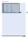
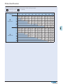
Influence of the ambient temperature to the maximum continuous current (A)
Ambient temperature
40°
45°
50°
55°
60°
16A
2p
16
14
11
9
– *)
25A
2p
25
21
18
14
–*)
4p
25
22
19
16
–*)
40A
2p
40
37
33
30
26
63A
2p
63
59
55
50
45
4p
40
37
34
31
27
4p
63
59
55
50
45
80A
4p
80
76
72
68
64
100A
4p
100
95
90
85
80
Annotation: It has to be ensured that the values in the table are not exceeded and the back-up fuse/thermal protection works properly
*) not applicable
8
Protective Devices
Residual Current Devices PF6
•
•
•
•
•
•
•
•
•
•
•
•
•
Twin-purpose terminal (lift/open-mouthed) above and below
Busbar positioning optionally above or below
Free terminal space despite installed busbar
Universal tripping signal switch, also suitable for PLS., PKN., Z-A. can be
mounted subsequently
Auxiliary switch Z-HK can be mounted subsequently
Contact position indicator red - green
Suitable for being used with standard fluorescent tubes with or without
electronical ballast (typically up to 20 units per phase conductor)
The device functions irrespective of the position of installation
Mains connection at either side
The 4-pole device can also be used for 3-pole connection.
For this purpose use terminals 1-2, 3-4, and 5-6 (+ cable link).
The 4-pole device can also be used for 2-pole connection.
For this purpose use terminals 5-6 and N-N.
The test key “T” must be pressed every month. The system operator must
be informed of this obligation and his responsibility in a way that can be
proven (self-adhesive RCD-label enclosed)
Pressing the test key “T” serves the only purpose of function testing the
residual current device (RCD). This test does not make earthing resistance
measurement (RE), or proper checking of the earth conductor condition
redundant, which must be performed separately.
Accessories:
Auxiliary switch for
subsequent installation to the left
Tripping signal contact for
subsequent installation to the right
Remote control and
automatic switching device
Compact enclosure
Sealing cover set
Switching interlock
Z-HK
248432
Z-NHK
248434
Z-FW/LP
KLV-TC-2
KLV-TC-4
Z-RC/AK-2TE
Z-RC/AK-4TE
IS/SPE-1TE
248296
276240
276241
285385
101062
101911
Connection diagrams
2-pole
4-pole
1 3 5 N
T
2 4 6 N
Technical Data
Electrical
Design according to
IEC/EN 61008
Current test marks as printed onto the device
Tripping
instantaneous
Rated voltage Un
230/400 V, 50 Hz
Rated tripping current IΔn
30, 300 mA
Sensitivity
AC and pulsating DC
Rated insulation voltage Ui
440 V
Rated impulse withstand voltage Uimp 4 kV
Rated short circuit strength Inc
6 kA
Maximum back-up fuse
Overload
Short circuit
In = 25-40 A
25 A gG/gL 63 A gG/gL
In = 63 A
40 A gG/gL 63 A gG/gL
Rated breaking capacity Im or
Rated fault breaking capacity IΔm
In = 16-40 A
500 A
In = 63 A
630 A
Voltage range of test button 2-pole
184 - 250 V~
4-pole
184 - 440 V~
Endurance
electrical comp.
≥ 4,000 operating cycles
mechanical comp.
≥ 20,000 operating cycles
Mechanical
Frame size
Device height
Device width
Dimensions (mm)
RCD PF6 in a Three-Phase AC Network without Neutral Conductor
2P
5,5
4P
80
30,5
Mounting
Degree of protection, built-in
Deg. of prot. in moisture-proof encl.
Upper and lower terminals
Terminal protection
Terminal capacity
Busbar thickness
Tripping temperature
Storage- and transport temperature
Resistance to climatic conditions
4,5
L1
L2
L3
L1
L2
L3
45
80
45 mm
80 mm
35 mm (2MU),
70 mm (4MU)
quick fastening with
2 lock-in positions on
DIN rail IEC/EN 60715
IP40
IP54
open mouthed/lift terminals
finger and hand touch safe,
BGV A3, ÖVE-EN 6
1x (1.5 - 35) mm2 single wire
2x (1.5 - 16) mm2 multi wire
0.8 - 2 mm
-25°C to +40°C
-35°C to +60°C
25-55°C/90-95% relative
humidity acc. to IEC 60068-2
The N-terminal must be connected by a cable link
with the phase L2 (or L1), so that the test loop is
supplied with current and the RCD is tested correctly.
10,5
35
44
70
60
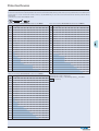
Influence of the ambient temperature to the maximum continuous current (A)
Ambient temperature
40°
45°
50°
55°
60°
25A
2p
25
21
18
14
–*)
4p
25
22
19
16
–*)
40A
2p
40
37
33
30
26
4p
40
37
34
31
27
63A
4p
63
59
55
50
45
Annotation: It has to be ensured that the values in the table are not exceeded and the back-up fuse/thermal protection works properly
*) not applicable
9
Protective Devices
Residual Current Relays PFR., Core Balance Transformers Z-WFR.
• Residual current relays
• Shape compatible with and suitable for standard busbar connection to
other devices of the P-series
• Universal tripping signal switch, also suitable for PLS., PKN., Z-A. can be
mounted subsequently
• Auxiliary switch Z-HK can be mounted subsequently
• Contact position indicator red - green
• Delayed types suitable for being used with standard fluorescent tubes with
or without electronical ballast (30mA-RCD: 30 units per phase conductor,
100mA-RCD: 90 units per phase conductor)
Notes: Depending of the fluorescent lamp ballast manufacturer partly more
possible. Symmetrical allocation of the fluorescent lamp ballasts on all
phases favourably. Shifting references of the fluorescent lamp ballast manufacturer consider.
• The test key “T” must be pressed every month. The system operator must
be informed of this obligation and his responsibility in a way that can be
proven (self-adhesive RCD-label enclosed)
• Type -U: Suitable for speed-controlled drives with frequency converters in
household, trade, and industry.
Unwanted tripping is avoided thanks to a tripping characteristic designed
particularly for frequency converters.
See also explanation “Frequency Converter-Proof RCDs - What for?”
Application according to ÖVE/ÖNORM E 8001 and Decision EN 219 (1989),
VDE 0100, SEV 1000.
Accessories:
Auxiliary switch for
subsequent installation to the left
Tripping signal contact for
subsequent installation to the right
Compact enclosure
Sealing cover set
Switching interlock
Z-HK
248432
Z-NHK
KLV-TC-4
Z-RC/AK-4TE
IS/SPE-1TE
248434
276241
101062
101911
Connection diagrams
Relay
Core balance transformer
L1 L2 L3 N
1
2
3
4
1
2
3
4
Technical Data
Electrical
Design according to
IEC/EN 61008
Current test marks as printed onto the device
Tripping
40 ms delay
with selective disconnecting
function
Rated voltage Un
230/400 V; 50 Hz
Rated tripping current IΔn
(0.1)*), 0.3 and 1 A
Rated current
25 A / 400 V~,
of relay contacts
16 A / 230 V AC 15
Maximum nominal current
400 A
Sensitivity
pulsating DC
Rated peak withstand voltage Uimp
4 kV (1.2/50µs)
Voltage range of test button
184 - 440 V~
Endurance
electrical comp.
≥ 4,000 operating cycles
mechanical comp.
≥ 20,000 operating cycles
Mechanical
Frame size
Device height
Device width
Mounting
45 mm
80 mm
70 mm (4MU)
quick fastening with
2 lock-in positions on
DIN rail IEC/EN 60715
Degree of protection, built-in
IP40
Upper and lower terminals
open mouthed/lift terminals
Terminal protection
finger and hand touch safe,
BGV A3, ÖVE-EN 6
Terminal capacity
1.5 - 35 mm2 single wire
2 x 16 mm2 multi wire
Busbar thickness
0.8 - 2 mm
Control line
1.5 - 2.5 mm2
Tripping temperature
-25°C to +40°C
Storage- and transport temperature
-35°C to +60°C
Resistance to climatic conditions
25-55°C/90-95% relative
humidity acc. to IEC 60068-2
*) see Important Information for Installation
Dimensions (mm)
5,5
4P
PFR
30,5
4,5
Z-WFR 2-S/A / Z-WFR 2-U
45
80
10,5
70
44
60
10
Z-WFR 3-S/A / Z-WFR 3-U
Protective Devices
Important Information for Installation
All lines required for operation, L1, L2, and L3 including neutral N, must be routed through the transformer as follows:
Insulated lines must be laid bunched
Copper rails
Maximum distance d between copper rails 10 mm
Impulse Contact Control
Continuous Contact Control
LineNetz
voltage
LineNetz
voltage
13 14 15 16
L1 L2 L3 N
PFR
1
2
DurchsteckCore
balance
transformer
wandler
Z-WFR
Z-WFR
13 14 15 16
L1 L2 L3 N
PMA
PT
AE
RP
PFR
1 2 3 4
1
2
DurchsteckCore
balance
transformer
wandler
Z-WFR
Z-WFR
3
4
15
PMA
PT
AE
RP
1 2 3 4
3
4
15
13
13
16
14
Schütz
Contactor
16
14
Schütz
Contactor
Schaltuhr,
Timer,
thermostat,
Thermostat
etc.
etc.
DruckknopfPushbutton
steuerung
control
Consumer
Verbraucher
Consumer
Verbraucher
Erdung
Earth
Earth
Erdung
Two possible switching examples.
Attention: • Connect terminals 1-4 of the relay to the terminals 1-4 of the transformer (see switching examples)!
1+2: secondary winding; 3+4: test winding
• Supply terminals 13 and 15 as shown, so that the test circuit can work correkt!
Rated Tripping Current Matching
Matching of the rated tripping current, 0.1 or 0.3 A, is achieved by the number of turns in the primary winding of the transformer (in PFR203-S/A, PFR3-03-S/A, PFR2-03-U and PFR3-03-U).
Residual Current
Relay
Transformer
PFR2-03-U (S/A)
Z-WFR2
PFR3-03-U (S/A)
Z-WFR3
Rated tripping
Number of
Maximum cable
Maximum
current IΔN (A)
primary turns
diameter (mm)
primary current (A)
0,1
3
60
150
0,3
1
60
400
0,1
3
130
65
0,3
1
130
400
PFR2-1-U (S/A)
Z-WFR2
1,0
1
60
400
PFR3-1-U (S/A)
Z-WFR3
1,0
1
130
400
11
Protective Devices
Residual Current Devices PFDM
• Residual current devices
• Tripping is line voltage-independent. Consequently, the RCD is suitable for
the protection of humans and additional protection (ÖVE/ÖNORM E 8001-1
§ 6.1.2)
• Twin-purpose terminal (lift/open-mouthed) above and below
• Not busbar-compatible with other devices of the P-series
• Auxiliary switch Z-HD can be mounted subsequently
• Contact position indicator red - green
• The device functions irrespective of the position of installation
• Tripping is line voltage-independent. Consequently, the RCD is suitable for
“fault current/residual current protection” and “additional protection” within the the meaning of the applicable installation rules
• Mains connection at either side
• The test key “T” must be pressed every month. The system operator must
be informed of this obligation and his responsibility in a way that can be
proven (self-adhesive RCD-label enclosed)
• Type -A: Additionally protects against special forms of residual pulsating
DC which have not been smoothed.
• Type -S/A: Compulsory for systems with surge arresters downstream of
the RCD (ÖVE/ÖNORM E 8001-1 § 12.1.5).
Accessories:
Auxiliary switch for
subsequent installation to the left
Z-HD
265620
Connection diagrams
2-pole
4-pole
Z-HD
Technical Data PFDM
Electrical
Design according to
IEC/EN 61008
Current test marks as printed onto the device
Tripping
instantaneous
Typ S/A 40 ms delay with selective disconnecting
function
Rated voltage Un
230/400 V; 50 Hz
Rated tripping current IΔn
30, 100, 300, 500 mA
Sensitivity
AC and pulsating DC
Rated short circuit strength Inc
10 kA with back-up fuse
Maximum back-up fuse
Short circuit 125 A gG/gL
Rated breaking capacity Im or
Rated fault breaking capacity IΔm
1250 A
Voltage range of test button
2-pole
100 - 250 V~
4-pole
185 - 440 V~
Endurance
electrical comp.
≥ 4,000 operating cycles
mechanical comp.
≥ 20,000 operating cycles
Mechanical
Frame size
Device height
Device width
Mounting
Degree of protection, built-in
Upper and lower terminals
Terminal protection
Terminal capacity
Busbar thickness
Tripping temperature
Storage- and transport temperature
Resistance to climatic conditions
45 mm
85 mm
36 mm (2P), 72 mm (4P)
quick fastening on
DIN rail IEC/EN 60715
IP40
open mouthed/lift terminals
finger and hand touch safe,
BGV A3, ÖVE-EN 6
1.5 - 50 mm2
0.8 - 2 mm
-25°C to +40°C
-35°C to +60°C
25-55°C/90-95% relative
humidity acc. to IEC 60068-2
Technical Data Auxiliary Switch Z-HD
Electrical
Subsequent installation to the left onto
Contacts
Load rating
AC11
DC11
PFDM
1CO + 1NC
Mechanical
Terminal capacity
6 A / 230 V AC
1 A / 230 V DC
Dimensions (mm)
Function Auxiliary Switch
Tripping signal switch: detects if RCD tripping occured by
an fault current
Auxiliary switch: shows the contact position of the RCD
12
up to 2.5 mm2
Protective Devices
Residual Current Devices CFI6
• Residual current devices
• Tripping is line voltage-independent. Consequently, the RCD is suitable for
fault current/residual current protection and additional protection
(ÖVE/ÖNORM E 8001-1 § 6.1.2)
• Matching with CLS6, CLS4
• Shape compatible with and suitable for standard busbar connection to
other devices of the C-series
• Twin-purpose terminal (lift/open-mouthed) above and below
• Busbar positioning optionally above or below
• Free terminal space despite installed busbar
• Universal tripping signal switch, also suitable for CLS., CKN., Z-A. can be
mounted subsequently
• Auxiliary switch Z-HK can be mounted subsequently
• Contact position indicator red - green (CFI6-4-pole)
• Suitable for being used with standard fluorescent tubes with or without
electronical ballast (typically up to 20 units per phase conductor)
• The device functions irrespective of the position of installation
• Tripping is line voltage-independent. Consequently, the RCD is suitable for
“fault current/residual current protection” and “additional protection” within the the meaning of the applicable installation rules
• Mains connection at either side
• The 4-pole device can also be used for 3-pole connection.
For this purpose use terminals 1-2, 3-4, and 5-6 (+ cable link).
• The 4-pole device can also be used for 2-pole connection.
For this purpose use terminals 5-6 and N-N.
• The test key “T” must be pressed every month. The system operator must
be informed of this obligation and his responsibility in a way that can be
proven (self-adhesive RCD-label enclosed)
• Pressing the test key “T” serves the only purpose of function testing the
residual current device (RCD). This test does not make earthing resistance
measurement (RE), or proper checking of the earth conductor condition
redundant, which must be performed separately.
• Type -A: Protects against special forms of residual pulsating DC which
have have not been smoothed
Accessories:
Auxiliary switch for
subsequent installation to the left
Remote tripping module
Switching interlock
Z-HK
Z-FAM
IS/SPE-1TE
248432
248293
101911
Connection diagrams
2-pole
4-pole
1 3 5 N
T
2 4 6 N
Technical Data
Electrical
Design according to
IEC/EN 61008
Current test marks as printed onto the device
Tripping
instantaneous
Rated voltage Un
230/400 V; 50 Hz
Rated tripping current IΔn
30, 100, 300, 500 mA
Sensitivity
AC and pulsatory DC
Rated insulation voltage Ui
440 V
Rated peak withstand voltage Uimp
4 kV (1.2/50µs)
Rated short circuit strength Inc
6 kA
with back-up fuse 63 A gG/gL
Maximum back-up fuse
Short circuit 63 A gG/gL
Rated breaking capacity Im or
Rated fault breaking capacity IΔm
In = 25-40A
500 A
In = 63A
630 A
Voltage range of test button 2-pole
184 - 250 V~
4-pole
184 - 440 V~
Endurance
electrical comp.
≥ 4,000 operating cycles
mechanical comp.
≥ 20,000 operating cycles
Mechanical
Frame size
Device height
Device width
Dimensions (mm)
RCD CFI6 in a Three-Phase AC Network without Neutral Conductor
2P
4,5
4P
80
Mounting
Degree of protection, built-in
Upper terminals
Lower terminals
Terminal protection
Terminal capacity
Busbar thickness
Tripping temperature
Storage- and transport temperature
Resistance to climatic conditions
41
L1
L2
L3
L1
L2
L3
45
80
8
35
70
43
60
13
45 mm
80 mm
35 mm (2MU),
70 mm (4MU)
quick fastening with
2 lock-in positions on
DIN rail IEC/EN 60715
IP40
lift terminals
open-mouthed/lift terminals
finger and hand touch safe,
BGV A3, ÖVE-EN 6
1.5 - 35 mm2 single wire
2 x 16 mm2 multi wire
0.8 - 2 mm
-25°C to +40°C
-35°C to +60°C
25-55°C/90-95% relative
humidity acc. to IEC 60068-2
The N-terminal must be connected by a cable link
with the phase L2 (or L1), so that the test loop is
supplied with current and the RCD is tested correctly.
Protective Devices
Residual Current Devices dRCM - digital
• Residual current devices
• Shape compatible with and suitable for standard busbar connection to
other devices of the P-series
• Twin-purpose terminal (lift/open-mouthed) above and below
• Busbar positioning optionally above or below
• Free terminal space despite installed busbar
• Universal tripping signal switch, also suitable for PLS., PKN., ZP-A. can be
mounted subsequently
• Auxiliary switch Z-HK can be mounted subsequently
• Contact position indicator red - green
• Tripping indicator white - blue
• Additional Safety
- possibility to seal
- possibility to lock in ON and OFF position
• Delayed types suitable for being used with standard fluorescent tubes with
or without electronical ballast (30mA-RCD: 30 units per phase conductor,
100mA-RCD: 90 units per phase conductor)
Notes: Depending of the fluorescent lamp ballast manufacturer partly more
possible. Symmetrical allocation of the fluorescent lamp ballasts on all
phases favourably. Shifting references of the fluorescent lamp ballast manufacturer consider.
• The device functions irrespective of the position of installation
• Tripping is line voltage-independent. Consequently, the RCD is suitable for
“fault current/residual current protection” and “additional protection” within the meaning of the applicable installation rules
• Mains connection at either side
• The 4-pole device can also be used for 3-pole connection:
See connection possibilities.
• The 4-pole device can also be used for 2-pole connection:
See connection possibilities.
• The test key “T” must be pressed every year. The system operator must be
informed of this obligation and his responsibility in a way that can be
proven. The yearly test interval is only valid for residential and similar
applications. Under all other conditions (e.g. damply or dusty environment), it's recommended to test in shorter intervals (e.g. monthly).
A test is further needed if red and yellow LED are on together.
• Pressing the test key “T” serves the only purpose of function testing the
residual current device (RCD). This test does not make earthing resistance
measurement (RE), or proper checking of the earth conductor condition
redundant, which must be performed separately.
• Functioning
- The green LED becomes active at 0-30% IΔn
- The yellow LED becomes active at 30-50% IΔn
- The red LED becomes active at >50% IΔn
• Potential-free relay (NO contact, in parallel with the yellow LED, up to 1 A
ohmic load / 230 V~) for external prewarning function. Bistabile, means the
warning stays on also when the breaker trips, until reset.
• Type -A: Protects against special forms of residual pulsating DC which
have have not been smoothed
• Type -G: High reliability against unwanted tripping. Compulsory for any circuit where personal injury or damage to property may occur in case of
unwanted tripping (ÖVE/ÖNORM E 8001-1 § 12.1.6).
• Type -G/A: Additionally protects against special forms of residual pulsating
DC which have not been smoothed.
• Type -R: To aviod unwanted tripping due to X-ray devices.
• Type -S: Selective residual current device sensitive to AC, type -S.
Compulsory for systems with surge arresters downstream of the RCD
(ÖVE/ÖNORM E 8001-1 § 12.1.5).
• Type -S/A: Additionally protects against special forms of residual pulsating
pulsating DC which have not been smoothed.
• Type -U: Suitable for speed-controlled drives with frequency converters in
household, trade, and industry.
Unwanted tripping is avoided thanks to a tripping characteristic designed
particularly for frequency converters.
See also explanation “Frequency Converter-Proof RCDs - What for?”
Application according to ÖVE/ÖNORM E 8001-1 and Decision EN 219 (1989),
VDE 0100, SEV 1000.
Accessories:
Auxiliary switch for
subsequent installation to the left
Tripping signal contact for
subsequent installation to the right
Remote control and
automatic switching device
Compact enclosure
Sealing cover set
Switching interlock
Z-HK
248432
Z-NHK
248434
Z-FW/LP
KLV-TC-4
Z-RC/AK-4TE
IS/SPE-1TE
248296
276241
101062
101911
Connection diagram
4-pole
Technical Data
Electrical
Design according to
IEC/EN 61008
Type G and G/A acc. to
ÖVE E 8601
Current test marks as printed onto the device
Tripping
instantaneous
Type G , R
10 ms delay
Type S
40 ms delay with selective disconnecting
function
Type U (only 30 mA)
10 ms delay
Type U (without 30 mA)
40 ms delay with selective disconnecting
function
Rated voltage Un
230/400 and 240/415 V AC,
50/60 Hz
Operation voltage electronic
50 – 254V AC
Operation voltage test circuit
184 – 440V AC
Rated tripping current IΔn
30, 300 mA
Sensitivity
AC and pulsating DC
Rated insulation voltage Ui
440 V
Rated impulse withstand voltage Uimp 4 kV (1.2/50 µs)
Rated short circuit capacity Inc
10 kA
Peak withstand current
Type G, G/A, R, U (30mA)
3 kA (8/20 µs)
surge current proof
Type S/A, U (except 30mA)
typ. 5 kA (8/20 µs)
selective + surge current
proof
Electrical isolation
> 4 mm contact space
Maximum back-up fuse
In = 16-63A
In = 80A
In = 100A
Endurance
electrical comp.
mechanical comp.
Mechanical
Frame size
Device height
Device width
Mounting
Degree of protection, built-in
Deg. of prot. in moisture-proof encl.
Upper and lower terminals
Terminal protection
Terminal capacity
Terminal screw
Terminal capacity warning contact(s)
Terminal torque
Busbar thickness
Tripping temperature
Storage- and transport temperature
Resistance to climatic conditions
Contact position indicator
Tripping indicator
14
Short circuit and
overload protection
63 A gG/gL
80 A gG/gL
100 A gG/gL
≥ 4,000 operating cycles
≥ 20,000 operating cycles
45 mm
80 mm
70 mm (4MU)
quick fastening with
2 lock-in positions on
DIN rail IEC/EN 60715
IP40
IP54
open mouthed/lift terminals
finger and hand touch safe,
BGV A3, ÖVE-EN 6
1.5 - 35 mm2 single wire
2 x 16 mm2 multi wire
M5 (Pozidriv PZ2)
0.25-1.5 mm2 (plug in terminals)
2 - 2.4 Nm
0.8 - 2 mm
-25°C to +40°C
-35°C to +60°C
25-55°C/90-95% relative
humidity acc. to IEC 60068-2
red / green
white / blue
Protective Devices
Local Indication RCCB
Status indication LED
Permanent light green
red / yellow / green
Normal operation
Permanent light yellow
The measured residual current is bigger than 30% of the nominal
tripping value.
Permanent light red
The measured residual current is bigger than 50% of the nominal
tripping value.
Remote Indication
Standard Version:
Optional Version: (available upon request)
Terminal capacity of contacts:
1 contact NO up to 230V AC, 2 terminals, 1 A ohmic load
1 NO + 1 NC up to 110V AC/contact, 2x2 terminals, 1 A ohmic load
0.25 - 1.5 mm2
Dimensions (mm)
Correct connection
3+N
(230/400V)
3phase load without N
(400V AC Phase-Phase)
3phase load without N
(184V-254V AC Phase-Phase)
Test button works within 184V – 440V AC !, Electronic works within 50-254V AC !
15
1+N (230V)
Protective Devices
Residual Current Devices dRCM - digital, types B and B+
• Residual current devices, all-current sensitive
• Shape compatible with and suitable for standard busbar connection to
other devices of the P-series
• Twin-purpose terminal (lift/open-mouthed) above and below
• Busbar positioning optionally above or below
• Free terminal space despite installed busbar
• Universal tripping signal switch, also suitable for PLS., PKN., ZP-A. can be
mounted subsequently
• Auxiliary switch Z-HK can be mounted subsequently
• Contact position indicator red - green
• Tripping indicator white - blue
• Additional Safety
- possibility to seal
- possibility to lock in ON and OFF position
• Delayed types (G, S) suitable for being used with standard fluorescent
tubes with or without electronical ballast (30mA-RCD: 30 units per phase
conductor, 100mA-RCD: 90 units per phase conductor)
Notes: Depending of the fluorescent lamp ballast manufacturer partly more
possible. Symmetrical allocation of the fluorescent lamp ballasts on all
phases favourably. Shifting references of the fluorescent lamp ballast manufacturer consider.
• The device functions irrespective of the position of installation
• Tripping is line voltage-independent. Consequently, the RCD is suitable for
“fault current/residual current protection” and “additional protection” within the meaning of the applicable installation rules
• The 4-pole device can also be used for 3-pole connection:
See connection possibilities.
• The 4-pole device can also be used for 2-pole connection:
See connection possibilities.
• The test key “T” must be pressed every year. The system operator must be
informed of this obligation and his responsibility in a way that can be
proven. The yearly test interval is only valid for residential and similar
applications. Under all other conditions (e.g. damply or dusty environment), it's recommended to test in shorter intervals (e.g. monthly).
A test is further needed if red and yellow LED are on together.
• Pressing the test key “T” serves the only purpose of function testing the
residual current device (RCD). This test does not make earthing resistance
measurement (RE), or proper checking of the earth conductor condition
redundant, which must be performed separately.
• Functioning
- The green LED becomes active at 0-30% IΔn
- The yellow LED becomes active at 30-50% IΔn
- The red LED becomes active at >50% IΔn
• Potential-free relay (NO contact, in parallel with the yellow LED, up to 1 A
ohmic load / 230 V~) for external prewarning function. Bistabile, means the
warning stays on also when the breaker trips, until reset.
• Type -G/B und G/B+: High reliability against unwanted tripping.
Compulsory for any circuit where personal injury or damage to property
may occur in case of unwanted tripping (ÖVE/ÖNORM E 8001-1 § 12.1.6).
Protection against all types of fault currents.
• Type -S/B und S/B+: Selective residual current device. Protection against
all types of fault currents.
Accessories:
Auxiliary switch for
subsequent installation to the left
Tripping signal contact for
subsequent installation to the right
Remote control and
automatic switching device
Compact enclosure
Sealing cover set
Switching interlock
Z-HK
248432
Z-NHK
248434
Z-FW/LP
KLV-TC-4
Z-RC/AK-4TE
IS/SPE-1TE
248296
276241
101062
101911
Connection diagram
4-pole
Netz
Mains
Last
Load
Technical Data
Electrical
Design according to
IEC/EN 61008
IEC/EN 62423
B+ Type acc. to
VDE 0664-400
Formerly known as
VDE V 0664-110
Type G/B and G/B+
acc. to ÖVE E 8601
Current test marks as printed onto the device
Tripping
Type G
10 ms delay
Type S
40 ms delay with selective disconnecting
function
230/400 and 240/415 V AC,
Rated voltage Un
50 Hz
Operation voltage electronic
50 – 254V AC
Operation voltage test circuit
184 – 440V AC
Rated tripping current IΔn
30, 300 mA
Sensitivity
Alternating, pulsed and
direct currents
Rated insulation voltage Ui
440 V
Rated impulse withstand voltage Uimp 4 kV (1.2/50 µs)
Rated short circuit capacity Inc
10 kA
Peak withstand current
Type G/B and G/B+
3 kA (8/20 µs)
surge current proof
Type S/B and S/B+
typ. 5 kA (8/20 µs)
selective + surge current
proof
Electrical isolation
> 4 mm contact space
Maximum back-up fuse
In = 16-63A
In = 80A
Endurance
electrical comp.
mechanical comp.
Mechanical
Frame size
Device height
Device width
Mounting
Degree of protection, built-in
Deg. of prot. in moisture-proof encl.
Upper and lower terminals
Terminal protection
Terminal capacity
Terminal screw
Terminal capacity warning contact(s)
Terminal torque
Busbar thickness
Tripping temperature
Storage- and transport temperature
Resistance to climatic conditions
Contact position indicator
Tripping indicator
16
Short circuit and
overload protection
63 A gG/gL
80 A gG/gL
≥ 4,000 operating cycles
≥ 20,000 operating cycles
45 mm
80 mm
70 mm (4MU)
quick fastening with
2 lock-in positions on
DIN rail IEC/EN 60715
IP40
IP54
open mouthed/lift terminals
finger and hand touch safe,
BGV A3, ÖVE-EN 6
1.5 - 35 mm2 single wire
2 x 16 mm2 multi wire
M5 (Pozidriv PZ2)
0.25-1.5 mm2 (plug in terminals)
2 - 2.4 Nm
0.8 - 2 mm
-25°C to +40°C
-35°C to +60°C
25-55°C/90-95% relative
humidity acc. to IEC 60068-2
red / green
white / blue
Protective Devices
Local Indication RCCB
Status indication LED
Permanent light green
red / yellow / green
Normal operation
Permanent light yellow
The measured residual current is bigger than 30% of the nominal
tripping value.
Permanent light red
The measured residual current is bigger than 50% of the nominal
tripping value.
Remote Indication
Version:
Terminal capacity of contacts:
1 contact NO up to 230V AC, 2 terminals, 1 A ohmic load
0.25 - 1.5 mm2
Dimensions (mm)
Correct connection
Load side
Netzseite
Lastseite
Supply side
3+N
(230/400V)
Netzseite
Load side
Netzseite
Load
side
Lastseite
Supply
side
Lastseite
Supply
side
3-phase
application
2p
(230/400V)
Test button works within 184V – 440V AC !
17
Protective Devices
Residual Current Devices FI-B
•
•
•
•
•
•
•
•
•
•
•
•
•
Residual current devices - all fault-current sensitive
Twin-purpose terminal (lift/open-mouthed) above and below
Busbar positioning optionally above or below
Free terminal space despite installed busbar
Not busbar-compatible with other devices of the P series
Auxiliary switch Z-HD can be mounted at a later point in time
Contact position indicator red - green
The device functions irrespective of the position of installation
Tripping happens independent from line voltage (type A currents).
30 VAC are required to identify currents of type B.
Mains connection is at the top
The test key “T” must be pressed every month. The system operator must
be informed of this obligation and his responsibility in a way that can be
proven (self-adhesive RCD-label enclosed)
Pressing the test key “T” serves the only purpose of function testing the
residual current device (RCD). This test does not make earthing resistance
measurement (RE), or proper checking of the earth conductor condition
redundant, which must be performed separately.
Type B: All fault-current sensitive protective devices are designed for use
in 50 Hz AC systems with electrical equipment such as frequency converters, uninterruptible power supply systems, switch mains adapters or highfrequency power converters. In case of a fault, electronic equipment may
not only cause AC residual currents and pulsating DC residual currents, but
also pure DC and AC residual currents of different frequencies in which
case FI residual current devices of type AC and A will not trip.
Residual current devices of type PFDM-B, however, will identify all types of
fault currents in line with tripping characteristic B of the IEC 60755
standard, i.e. pure DC residual currents as well. In addition, they will also
identify all AC residual currents of all frequencies up to 1 MHz (100 kHz with
type S/B) in undulating (mixed) currents.
Accessories:
Auxiliary switch for installation on the left
at a later point in time
Z-HD
265620
Connection diagrams
2-pole
4-pole
Technical Data
Electrical
Design according to
IEC/EN 61008
Current test marks as printed onto the device
Tripping
short-time delayed
Type S/B 40 ms delayed selective switch-off
Rated voltage Un
230/400 V; 50 Hz
Rated tripping current IΔn
30, 100, 300, 500 mA
Peak withstand current
0,5µs/100kHz
Ring-Wave-Test
Sensitivity
All types of fault-current
Rated short circuit strength
10 kA
Maximum back-up fuse
Overload
Short circuit
10 A gG/gL
63 A gG/gL
In = 16A
In = 25-40A
25 A gG/gL 63 A gG/gL
In = 63A
40 A gG/gL 63 A gG/gL
In = 80A
50 A gG/gL 80 A gG/gL
In = 100A
63 A gG/gL 100 A gG/gL
Voltage range of test button
185 to 440 V~
Rated breaking capacity Im or
Rated fault breaking capacity IΔm
In = 16-40 A
500 A
In = 63-80 A
800 A
In = 125 A
1250 A
Endurance
electrical comp.
≥ 4,000 operating cycles
mechanical comp.
≥ 10,000 operating cycles
Mechanical
Frame size
Device height
Device width
Mounting
Degree of protection, built-in
Upper terminals
Lower terminals
Terminal protection
Terminal capacity
Busbar thickness
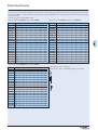
Admitted ambient temperature range
Resistance to climatic conditions
Mounting position
Dimensions (mm)
2p and 4p
18
45 mm
80 mm
70 mm (4MU) for 2p and 4p
quick fastening with
DIN rail EN50022
IP40
lift terminals
open-mouthed/lift terminals
finger and hand touch safe,
BGV A.
1,5 - 50 mm2
0,8 - 2 mm
-25°C to +40°C
according to IEC/EN 61008
any
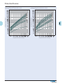
Protective Devices
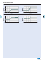
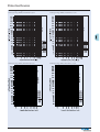
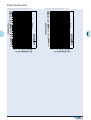
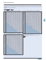
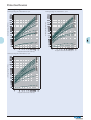
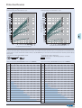
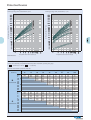
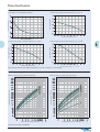
Tripping current frequency response 30 mA
Tripping current frequency response 100 mA
Tripping current frequency response 300 mA
Tripping current frequency response 500 mA
19
Protective Devices
Add-on Residual Current Protection Unit PBSM
• Add-on residual current unit
• Line voltage-independent tripping
• By combining this device with a top-quality miniature circuit breaker type PLS.
(exept PLSN.) a top-quality RCBO unit (combined RCD/MCB device) is formed.
• Rated current 40 and 63 A
• Permits combinations with a variety of characteristics thanks to the different rated currents and characteristics of the PLS.-miniature cirvuit breakers
which can be connected
• Comrehensive range of accessories suitable for subsequent installation
onto PLS.
• Type -A: Protect against special forms of residual pulsating DC which have
not been smoothed.
• Type -G: High reliability against unwanted tripping. Compulsory for any circuit where personal injury or damage to property may occur in case of
unwanted tripping (ÖVE-EN1, Part1, §12.14).
• Type -S: Selective residual current device, either sensitive to AC, type -S,
or sensitive to pulsating DC, type -S/A, for protection against special forms
of residual pulsating DC which have not been smoothed. Compulsory for
systems with surge arresters downstream of the RCD (ÖVE-EN1, Part 1,
§12.15).
Accessories :
Cover cap for draw-out connection bar
Slotted one-way cheese head screw
Accessories (on PLS.):
Auxiliary switch for
subsequent installation
ZP-IHK
ZP-WHK
Tripping signal contact for
subsequent installation
Remote control and automatic switching device
Shunt trip release
Undervoltage release
Compact enclosure
Additional terminal 35mm2
Switching interlock
286052
286053
ZP-NHK
Z-FW/LP
ZP-ASA/..
Z-USA/..
KLV-TC-2
KLV-TC-4
Z-HA-EK/35
IS/SPE-1TE
248437
248296
248438, 248439
248288-248291
276240
276241
263960
101911
Connection diagramms
2-pole
2 4
3-pole
T
2 4 6
4-pole
T
2’ 4’
2 4 6 8N
T
2’ 4’ 6’
2’ 4’ 6’ 8N’
included
included
Technical Data
Electrical
Design according to
IEC/EN 61009
Current test marks as printed onto the device
Tripping
instantaneous 250A (8/20µs),
surge current-proof
Type G 10 ms delay 3kA (8/20µs),
surge current-proof
Type S 40 ms delay 6kA with selective disconnecting
function
Rated voltage Un
230/400 V AC
Operational voltage range
196 - 440 V
Rated frequency
50 Hz
Use at 162/3 Hz
Recesses time between the
single switchings increases
to 88 s, In max. 63 A
Use at 400 Hz
In max. 40 A
Rated current In
≤ 40 A, ≤ 63 A
Rated tripping current IΔn
30, 100, 300, 500, 1000 mA
Rated non-tripping current IΔno
0.5 IΔn
Sensitivity
AC and pulsating DC
Service short circuit breaking capacity Ics same as connected PLS. (7.5 kA)
Rated breaking capacity Icn
same as connected PLS. (10 kA)
Rated fault breaking capacity IΔm
6 kA (Un = 230V)
3 kA (Un = 400V)
Mechanical
Frame-size
Device height
Device width
Mounting
Degree of protection installed device
Fastening screw
Screw head breaking torque
Upper and lower terminals
Terminal screws
Terminal protection
Terminal capacity
Rigid conductors
Flexible conductors (with wire
end sleeve)
Busbar thickness
Permitted ambient temperature range
Resistance to climatic conditions
Dimensions (mm)
20
45 mm
90 mm
70 mm (2p), 107.5 mm (3p),
125 mm (4p)
fix mounted onto PLS.
IP40
M 2.5 (slotted one-way
cheese head screw;
> 0.6 Nm
lift terminals
M 5 (combined Philips/standard head screws according
to DIN7962-Z2, Pozidrive)
finger and hand touch safe,
BGV A3, ÖVE-EN 6
1 x (1 - 25) mm2
1 x (0.75 - 16) mm2
0.8 - 2 mm
-25°C to +40°C
acc. to IEC/EN 60068-2
(25..55°C/90..95% relative humidity)
Protective Devices
Add-on Residual Current Protection Unit PBHT
• By combination with miniature circuit breaker PLHT => RCBO-Unit (MCCB)
• Add-on residual current unit (screw connection) for 80 or 125 A
(2-pole and 4-pole)
• High flexibility and ease of installation thanks to variable wiring (400 mm
flexible connection wires 2p = 2 units, 4p = 4 units included in the set)
• Free selection of main power supply
• Auxiliary switch 1 NO included as standard in all PBHT versions
• Permits combinations with a variety of characteristics thanks to the different rated currents and characteristics of the miniature circuit breakers PLHT
which can be connected
• For trade and industry applications
• For subsequent mounting onto 2, 3, 3+N and 4-pole-miniature circuit breakers PLHT
• Toggle (serves as switch position- and tripping indicator)
• The screw connection to the PLHT-device can be unscrewed at any time.
Consequently, in case of modifications of the systems to be protected, the
installation can be adapted to new requirements at any time.
Accessories:
Flexible connection wires (connection to PLHT) are included in the standard
set:
2-pole 80A
2 x 16mm2 (400mm each)
4-pole 80A
4 x 16mm2 (400mm each)
2-pole 125A
2 x 35mm2 (400mm each)
4-pole 125A
4 x 35mm2 (400mm each)
Connection diagrams
2-pole
4-pole
Technical Data
Electrical
Design according to
IEC/EN 61009
Current test marks as printed onto the device
Current flow paths
Rated voltage Ue
230/400 V AC
Operational voltage range
196-440 V
Rated frequency
50 Hz
Rated current In
80 A, 125 A
Rated tripping current IΔn
30, 300, 500, 1000 mA
Rated non-tripping current IΔno
0.5 IΔn
Sensitivity
AC and pulsating DC
Tripping characteristic
instantaneous 250A (8/20µs),
surge current-proof;
Type S 40 ms delay 6kA (8/20µs)
with selective disconnecting
function,
surge current-proof
Rated service short circuit breaking capacity Icn same as connected PLHT
Rated ultimate circuit breaking capacity Icu same as connected PLHT
= Icu
Rated fault short circuit breaking capacity IΔ/n
4 kV (1.2/50µs)
Rated peak withstand voltage Uimp
Endurance mechanical comp.
PBHT-80
>10000
PBHT-125
>8000
Endurance electrical comp.
PBHT-80
>1500
PBHT-125
>1000
Auxiliary Contact
Utilisation category AC15
Rated voltage Ue
Rated operational current Ie
Mechanical
Frame size
Device height
Device width
Depth of central body
Mounting
Upper and lower terminals
Terminal protection
Terminal capacity
Main conductor
Auxiliary switch
Degree of protection, built-in
Permissible ambient temperature range
Resistance to climatic conditions
Dimensions (mm)
PBHT/2p + PLHT/2p
PBHT/4p + PLHT/3p+N
PBHT/4p + PLHT/3p
PBHT/4p + PLHT/4p
21
250 V AC
16 A AC
45 mm
90 mm
95 mm (5.5MU)
60 mm
screwed onto PLHT
2-, 3-, 4-pole; PBHT-ASA
lift terminals
finger and hand touch safe,
BGV A3, ÖVE-EN 6
2.5 - 50 mm2
1 - 25 mm2
IP40
-25°C to +40°C
25-55°C/90-95% relative
humidity acc. to IEC 60068-2
Protective Devices
Wiring options
Mounting PBHT + PLHT
SG15402
SG15102
PBHT
+
PLHT
Connection PBHT/4p + PLHT/3p
PBHT/4p
SG15202
PLHT/3p
SG15302
Mounting arrangement residual current protection unit - shunt trip release - miniature circuit breaker - auxiliary contact
PBHT-2-pole
Z-PBHT-ASA
PBHT-4-pole
PLHT-3+N-pole
Z-LHK
13
1
21
+
+
+
22
14
2
22
Protective Devices
Accessories for PBHT
Shunt Trip Release Z-BHASA
•
•
•
•
•
Can be mounted subsequently
Contact position indicator red - green
Marking labels can be fitted
Wide operational voltage range
Sufficient power of extra low voltage source must be ensured
PBHT-ASA/24: min. 90 VA
• Screws for mounting included PBHT => BHASA => PLHT
Connection diagram
1
2
Technical Data
Z-BHASA/24
Z-BHASA/230
15 ms
2Ω
100%
< 20 ms
2 kV
>4,000 operating cycles
10 ms
130 Ω
100%
< 20 ms
2 kV
>4,000 operating cycles
Electrical
Minimum pulse duration
Internal resistance
Duty
Tripping time
Peak withstand voltage (1.2/50µs)
Endurance
AC voltage range:
Responding limit
Operational voltage range
Maximum current consumption during switch-on
Current flow time at max. current consumption
DC voltage range:
Responding limit
Operational voltage range
Maximum current consumption during switch-on
Current flow time at max. current consumption
8V
12-60 V
1.4-7 A
4.0 ms
70 V
110-415 V
3.4 A (at 230V)
4.5 ms
11 V
12-60 V
1.7 A typ.
2 ms
90 V
110-230 V
1.7 A typ.
4 ms
Mechanical
Frame size
Device height
Device width
Mounting
Degree of protection, built-in
Upper and lower terminal screws
Terminal capacity
Fastening torque of terminal screws
45 mm
45 mm
90 mm
90 mm
27 mm
27 mm
quick fastening on DIN rail IEC/EN 60715
IP40
IP40
lift terminals
lift terminals
2.5-30 mm2
2.5-30 mm2
4 Nm
4 Nm
Dimensions (mm)
23
Protective Devices
PBR Main Protective Device
ATTENTION:
The main protective device does not replace a residual current device (RCD).
For protection against residual current or additional protection you still need
to install an RCD even if you use a main protective device.
The objective of the PBR main protective device is preventive fire protection
only.
•
•
•
•
•
•
•
•
•
•
•
•
•
•
•
•
Accessories:
Auxiliary switch
for retro-fitting on the left side (4p)
Tripping signal contact
for retro-fitting on the right side
Reset device
Small enclosure
Lead-seal set
Anti-tamper device
Tripping current identification (IΔn) is independent of the line voltage
Integrated overload protection
Contour and busbar compatible with other devices of the P series
Double-comfort terminal lift/open-mouthed at top and bottom
Free selection of the busbar arrangement at top and bottom
Connection
Free terminal space despite the fitted busbar
4-pole
Universal Z-NHK tripping signal switch can be retro-fitted
Auxiliary Z-HK switch can be retro-fitted
Contact position indicator red - green
Suitable for use with commercially available standard fluorescent lamps
with or without electronic ballast
The function of the switch is independent of its position
Mains connection on any side
The 4-pole switch cannot be used as a 3-pole switch
The 4-pole switch can also be used as a 2-pole switch
In this case use terminals 1-2 and N-N (+ wire bridge, see instructions).
The test button “T” needs to be activated once a year. This fact and responsibility needs to be communicated to the system operator in a provable
manner.
Due to their tripping characteristics the main protective devices feature full
selectivity with regard to downstream electromagnetic quick tripping relays
of MCBs according to EN 60898-1 and of “general” and “S” types of RCD
protective devices according to EN 61008-1.
Main protective devices are particularly important as fire protection in
3L+PEN ~400/230 V networks (TN-systems).
Main protective devices are particularly important as back-up protection
against electrical shocks in 3L+N ~400/230 V networks (TT-systems)
Z-HK
248432
Z-NHK
Z-FW/LP
KLV-TC-4
Z-RC/AK-4TE
IS/SPE-1TE
248434
248296
276241
101062
101911
diagram
Technical Data
Electrical
Current test marks as printed onto the device
Tripping
200 ms delayed
selective switch-off
Rated voltage Un
230/400 V; 50 Hz
Fire protection residual current IΔn
300 mA
Sensitivity
AC
Rated insulation voltage Ui
440 V
4 kV
Rated peak withstand voltage Uimp
Rated short circuit strength Inc
10 kA
Max. back-up fuse as overload
63 A gG/gL
and short-circuit protection
Rated making and breaking capacity Im or
Rated residual making/breaking cap. IΔm
Voltage range of test button
Endurance
electrical
mechanical
630 A
195.5 - 440 V~
≥ 4.000 operating cycles
≥ 20.000 operating cycles
Mechanical
Frame size
Device height
Installation width
Mounting
45 mm
80 mm
70 mm (4U)
Quick fastening with
2 lock-in positions for
DIN rail IEC/EN 60715
Degree of protection, built-in
IP40
Upper and lower terminals
Open-mouthed/lift terminals
Terminal protection
Finger and hand touch safe
acc. to BGV A3, ÖVE-EN 6
Terminal capacity
1.5 - 35 mm2 single-wired
2 x 16 mm2 multi-wired
Material thickness of busbar
0.8 - 2 mm
Permitted ambient temperature range -25°C to +40°C
Resistance to climatic conditions
25-55°C/90-95% relative
humidity acc. to IEC 60068-2
Dimensions (mm)
24
Protective Devices
PDIM Leackage Current Monitor
Test function
• Shape compatible with and suitable for standard busbar connection to
• The rotary coding switch for the RCD switch function is to be set to “TEST”.
other devices of the P-series
The device then alternately simulates residual currents of 30% and 50% of
• Twin-purpose terminal (lift/open-mouthed) above and below
the IΔn. In this process, the yellow and red LED flash alternately (1 Hz), both
• Busbar positioning optionally above or below
• Free terminal space despite installed busbar
output relays remain permanently energised.
• Power supply via ‘OR’ disjunction of the 4 conductors
• Electronic functioning (line-voltage independent)
• The device works irrespective of the position of installation
Connection diagram
• Mains connection at either side
4-pole
• The 4-pole device can also be used for 3-pole connection.
For this purpose use terminals 1-2, 3-4, and 5-6.
• The 4-pole device can also be used for 2-pole connection.
For this purpose use terminals 5-6 and N-N.
• 2 potential-free relays (make contact, in parallel with the yellow and red
LED) (up to 10 A / 230 V~)
Functioning
• The green LED becomes active at 0-30% of the preset IΔn.
The yellow LED becomes active at 30-50% of the preset IΔn.
The red LED becomes active at >50% of the preset IΔn.
• The yellow LED turns off again when the identified residual current is <30%
of the preset IΔn.
• The red LED stays on even if the identified residual current is <50% of the
preset IΔn.
• The red LED will only turn off after pressing the reset button.
• Only one LED will be active at a time.
• An output relay will always be switched simultaneously with the yellow or
red LED
• Depending on the setting of the type of RCD (instantaneous, G, S), the
residual current needs to flow a sufficiently long time before an action is
triggered.
Technical Data
Electrical
Design similar to
DIN/EN 62020
Current test marks as printed onto the device
Rated current In
40 A, 100 A
Tripping behaviour (adjustable)
instantaneous
Type G
10 ms delay
Type S
40 ms delay selective
Rated voltage Un
230/400 V, 50/60 Hz
240/415 V, 50/60 Hz
Rated tripping current IΔn (adjustable)
30, 100, 300, 500, 1000 mA
Sensitivity
AC and pulsating DC
Rated insulation voltage Ui
440 V
Rated short circuit resistance Inc
10 kA
Max. back-up fuse admitted
Short-circuit Overload
In = 40A
63 A gG/gL 40 A gG/gL
In = 100A
100 A gG/gL 63 A gG/gL
Switching contacts
potential-free 10 A / 230 V~
Tripping behaviour of the contacts
1: 30-50% IΔn
2: >50% IΔn
Endurance
electrical comp.
≥ 4,000 operating cycles
mechanical comp.
≥ 20,000 operating cycles
Mechanical
Frame size
Device height
Device width
Mounting
45 mm
80 mm
70 mm (4MU)
Quick fastening with
2 lock-in positions on
DIN rail IEC/EN 60715
Degree of protection, built-in
IP40
Degree of prot. in splash-proof encl.
IP54
Upper and lower terminals
Open-mouthed/lift terminals
Terminal protection
Protection against accidental
contact according to
BGV A3, ÖVE-EN 6
Terminal capacity (1, 2, 3, 4, 5, 6, N, N) 1.5 - 35 mm2 single-wired
2 x 16 mm2 multi-wired
Terminal capacity of switching contacts 0.25 - 1.5 mm2
Busbar thickness
0.8 - 2 mm
Admitted ambient temperature range -25°C to +40°C
Resistance to climatic conditions
25-55°C/90-95% relative
humidity acc. to IEC 60068-2
Dimensions (mm)
25
Protective Devices
Combined RCD/MCB Devices PKNM, 1+N-pole
•
•
•
•
•
•
•
•
•
•
•
Combined RCD/MCB device
Line voltage-independent tripping
Compatible with standard busbar
Twin-purpose terminal (lift/open-mouthed) above and below
Busbar positioning optionally above or below
Free terminal space despite installed busbar
Guide for secure terminal connection
Switching toggle (MCB component) in colour designating the rated current
Contact position indicator red - green
Comprehensive range of accessories suitable for subsequent installation
Type -A: Protects against special forms of residual pulsating DC which
have have not been smoothed
• Typ -G: 10 ms time delay in order to avoid unwanted tripping
(e.g. during thunderstorms).
Compulsory in Austria for any circuit where personal injury or damage to
property may occur in case of unwanted tripping (§12.1.6 ÖVE/ÖNORM
E 8001-1).
Accessories:
Auxiliary switch for
subsequent installation
Tripping signal switch for
subsequent installation
Shunt trip release
Tripping module
Terminal cover cap
Additional terminal 35mm2
Switching interlock
ZP-IHK
ZP-WHK
ZP-NHK
ZP-ASA/..
Z-KAM
KLV-TC-2
Z-HA-EK/35
IS/SPE-1TE
286052
286053
248437
248438, 248439
248294
276240
263960
101911
Connection diagram
1+N-pole
Technical Data
Electrical
Design according to
IEC/EN 61009
Current test marks as printed onto the device
Tripping
line voltage-independent
instantaneous 250A (8/20µs)
surge current-proof;
Type G 10 ms delay 3kA (8/20µs)
surge current-proof
Rated voltage Ue
230 V; 50 Hz
Operational voltage range
196-253 V
Rated tripping current IΔn
10, 30, 100, 300 mA
Rated non-tripping current IΔno
0.5 IΔn
Sensitivity
AC and pulsating DC
Selectivity class
3
Rated breaking capacity
10 kA
Rated current
2 - 40 A
Rated peak withstand voltage Uimp
4 kV (1.2/50µs)
Characteristic
B, C
Maximum back-up fuse (short circuit) 100 A gL (>10 kA)
Endurance
electrical comp.
≥ 4,000 operating cycles
mechanical comp.
≥ 20,000 operating cycles
Mechanical
Frame size
Device height
Device width
Mounting
Upper and lower terminals
Terminal protection
Terminal capacity
Busbar thickness
Degree of protection switch
Degree of protection, built-in
Tripping temperature
Storage- and transport temperature
Resistance to climatic conditions
Dimensions (mm)
5,5
30,5
4,5
T
80
45
9,5
35
44
60
26
45 mm
80 mm
35 mm (2MU)
3-position DIN rail clip,
permits removal from
existing busbar system
open mouthed/lift terminals
finger and hand touch safe,
BGV A3, ÖVE-EN 6
1 - 25 mm2
0.8 - 2 mm
IP20
IP40
-25°C to +40°C
-35°C to +60°C
acc. to IEC/EN 61009
Protective Devices
Load Capacity PKNM-../1N/
Tripping Characteristic PKNM-../1N/, Characteristics B a. C
Effect of ambient temperature (MCB component)
Tripping characteristic according to EN 61009
Ambient temperature
Defined non-tripping current
Defined tripping current
Short Circuit Selectivity PKNM-../1N/ towards DII-DIV fuse link
In case of short circuit, there is selectivity between the combined RCD/MCB devices PKNM../1N/ and the upstream fuses up to the specified values of the selectivity limit current Is [kA] (i. e. in case of short-circuit currents Iks under Is , only the MCB will trip, in case of short circuit currents above this value both protective devices will respond).
*) basically in accordance with EN 60898-1 D.5.2.b
Short circuit selectivity characteristic B towards fuse link DII-DIV*)
Short circuit selectivity characteristic C towards fuse link DII-DIV*)
PKNM DII-DIV gL/gG
PKNM DII-DIV gL/gG
In [A]
10
20
25
35
In [A]
10
20
25
35
2
<0.51) <0.51) 2.2
8.5
10.02) 10.02) 10.02) 10.02) 10.02)
2
<0.51) <0.51) 1.7
6.0
10.02) 10.02) 10.02) 10.02) 10.02)
4
<0.51) <0.51) 0.7
1.2
3.7
10.0
10.02) 10.02) 10.02)
4
<0.51) <0.51) 0.7
1.3
4.2
8.5
10.02) 10.02) 10.02)
6
<0.51) 0.7
1.0
2.9
6.9
10.02) 10.02) 10.02)
5
<0.51) <0.51) 0.6
1.1
3.6
7.0
10.02) 10.02) 10.02)
8
<0.51)
10.02)
10.02)
6
<0.51)
1.0
2.9
5.8
10.02) 10.02) 10.02)
8
<0.51) <0.5
0.9
2.5
4.8
10.02) 10.02) 10.02)
<0.5
0.7
1.5
2.6
5.3
9.0
10.02)
10
13
16
16
50
63
80
100
0.6
1.0
2.4
5.1
10.02)
0.6
0.9
1.9
3.3
7.0
10.02) 10.02)
10
0.5
63
80
100
0.7
1.6
2.8
5.7
9.0
0.7
1.4
2.4
4.4
7.0
10.02)
13
1.4
2.3
4.6
7.6
10.02)
16
1.2
1.8
3.4
5.5
10.02)
1.2
1.7
3.1
5.0
10.02)
1.6
2.9
4.6
10.02)
2.3
3.4
7.7
2.9
6.2
20
1.3
2.2
4.0
6.3
25
1.3
2.1
3.8
5.8
10.02)
20
2.0
3.5
5.2
9.5
25
3.1
4.5
8.1
32
40
0.6
50
10.02)
10.02)
32
16
40
1)
Selectivity limit current Is under 0.5 kA
Selectivity limit current Is = rated breaking capacity Icn of the RCD/MCB device
Darker areas: no selectivity
2)
27
Protective Devices
Short Circuit Selectivity PKNM-../1N/ towards D01-D03 fuse link
In case of short circuit, there is selectivity between the combined RCD/MCB devices PKNM../1N/ and the upstream fuses up to the specified values of the selectivity limit current Is [kA] (i. e. in case of short-circuit currents Iks under Is , only the MCB will trip, in case of short circuit currents above this value both protective devices will respond).
*) basically in accordance with EN 60898-1 D.5.2.b
Short circuit selectivity characteristic C towards fuse link D01-D03*)
Short circuit selectivity characteristic B towards fuse link D01-D03*)
PKNM D01-D03 gL/gG
PKNM D01-D03 gL/gG
In [A]
10
16
2
<0.51)
4
In [A]
10
10.02)
2
<0.51)
10.0
10.02) 10.02) 10.02)
25
35
50
63
80
100
1.6
3.3
10.02)
10.02)
10.02)
10.02)
<0.51) <0.51) 0.6
0.9
2.9
0.7
<0.51)
6
8
20
10.02)
16
0.5
20
0.5
25
35
50
63
80
100
2.4
10.02)
10.02)
10.02)
10.02)
10.02)
4
<0.51) <0.51) <0.51) 0.9
3.4
9.5
10.02) 10.02) 10.02)
10.02)
5
<0.51)
0.9
2.9
8.0
10.02) 10.02) 10.02)
<0.51)
<0.51)
0.5
0.8
2.4
8.2
10.02)
0.6
0.8
2.0
6.0
10.02) 10.02) 10.02)
6
<0.51) <0.51) 0.8
2.3
6.5
10.02) 10.02) 10.02)
10.02)
8
<0.5
0.7
2.1
5.5
9.5
10.02) 10.02)
<0.5
0.6
1.3
2.9
4.5
8.9
10.02)
10
0.5
0.8
1.6
3.7
6.0
10.02)
13
0.6
0.7
1.4
3.0
4.7
9.0
10.02)
10
13
1.2
2.5
3.9
7.6
10.02)
16
0.6
20
25
1.2
2.6
3.9
7.0
10.02)
1.2
2.5
3.6
6.2
10.02)
16
1.0
2.1
3.0
5.5
10.02)
20
1.0
2.0
2.7
5.0
10.02)
1.9
2.6
4.5
10.02)
2.1
3.4
10.02)
3.0
8.7
1.2
32
2.3
3.3
5.7
10.02)
2.3
3.1
5.1
10.02)
25
2.8
4.5
9.5
32
40
40
Short Circuit Selectivity PKNM-../1N/ towards NH-00 fuse link
In case of short circuit, there is selectivity between the combined RCD/MCB devices PKNM../1N/ and the upstream fuses up to the specified values of the selectivity limit current Is [kA] (i. e. in case of short-circuit currents Iks under Is , only the MCB will trip, in case of short circuit currents above this value both protective devices will respond).
*) basically in accordance with EN 60898-1 D.5.2.b
Short circuit selectivity characteristic B towards fuse link NH-00*)
Short circuit selectivity characteristic C towards fuse link NH-00*)
PKNM
PKNM
NH-00 gL/gG
In [A] 16
20
32
35
40
50
63
80
100 125 160
10.02)
10.02)
10.02)
10.02)
10.02)
10.02)
10.02)
2
<0.51)
2.8
4.4
10.02) 10.02) 10.02) 10.02) 10.02) 10.02)
2
<0.51)
1.1
3.6
10.02)
4
<0.51) 0.5
0.9
1.6
6
<0.51)
0.8
1.4
2.2
3.3
8
<0.51) <0.51) 0.7
1.0
1.9
2.8
0.5
NH-00 gL/gG
25
10.02)
In [A] 16
20
0.6
25
32
35
40
50
63
80
100 125 160
2.6
10.02)
10.02)
10.02)
10.02)
10.02)
10.02)
10.02) 10.02) 10.02)
4
<0.51) <0.51) 0.9
1.8
3.2
4.8
8.7
10.02) 10.02) 10.02) 10.02) 10.02)
7.0
10.02)
10.02)
10.02)
5
<0.51)
0.8
1.6
2.7
4.1
7.2
9.7
10.02) 10.02) 10.02) 10.02)
5.3
7.8
10.02) 10.02) 10.02) 10.02)
6
<0.51) <0.51) 0.7
1.3
2.2
3.3
5.9
8.0
10.02) 10.02) 10.02) 10.02)
8
<0.51)
0.6
1.1
1.9
2.8
5.0
6.7
10.02) 10.02) 10.02) 10.02)
0.5
0.8
1.2
1.7
2.7
3.4
5.5
10.02) 10.02) 10.02)
10.02)
10.02)
10
<0.51)
0.7
0.9
1.5
2.1
3.4
4.3
7.3
10.02)
13
<0.51) 0.6
0.8
1.4
1.8
2.8
3.6
5.7
10.02) 10.02) 10.02)
10
10.02)
10.02)
13
1.1
1.5
2.3
2.9
4.7
10.02) 10.02) 10.02)
16
20
25
32
40
0.6
10.02)
10.02)
<0.51)
<0.51)
0.7
1.2
1.5
2.4
3.0
4.5
10.02)
0.7
1.1
1.5
2.2
2.8
4.2
9.2
10.02) 10.02)
16
1.0
1.3
1.8
2.3
3.7
8.7
10.02) 10.02)
10.02)
20
0.9
1.1
1.7
2.2
3.4
8.0
10.02) 10.02)
1.6
2.1
3.2
7.2
10.02) 10.02)
1.7
2.6
5.3
9.0
10.02)
2.4
4.5
7.5
10.0
0.7
1.1
1.4
2.1
2.6
4.0
8.2
10.02)
1.0
1.4
2.0
2.5
3.7
7.1
10.02) 10.02)
25
6.2
10.02)
32
2.3
3.4
8.8
40
1)
Selectivity limit current Is under 0.5 kA
Selectivity limit current Is = rated breaking capacity Icn of the RCD/MCB device
Darker areas: no selectivity
2)
28
Protective Devices
Let-through energy PKNM, characteristic B, 1+N-pole
Let-through energy PKNM, characteristic C, 1+N-pole
Let through energy I2t [A2 sec]
Let through energy I2t [A2 sec]
Let-through Energy PKNM-../1N/
Prospective short-circuit current [A]
Prospective short-circuit current [A]
29
Protective Devices
Combined RCD/MCB Devices PKN6, 1+N-pole
•
•
•
•
•
•
•
•
•
•
•
Combined RCD/MCB device
Line voltage-independent tripping
Compatible with standard busbar
Twin-purpose terminal (lift/open-mouthed) above and below
Busbar positioning optionally above or below
Free terminal space despite installed busbar
Guide for secure terminal connection
Switching toggle (MCB component) in colour designating the rated current
Contact position indicator red - green
Comprehensive range of accessories suitable for subsequent installation
Type -A: Protects against special forms of residual pulsating DC which
have have not been smoothed
• Typ -G: 10 ms time delay in order to avoid unwanted tripping
(e.g. during thunderstorms) according to ÖVE E 8601.
Compulsory in Austria for any circuit where personal injury or damage to
property may occur in case of unwanted tripping (ÖVE-EN1, Part 1, §12.14).
Accessories:
Auxiliary switch for
subsequent installation
Tripping signal switch for
subsequent installation
Shunt trip release
Tripping module
Terminal cover cap
Additional terminal 35mm2
Switching interlock
ZP-IHK
ZP-WHK
ZP-NHK
ZP-ASA/..
Z-KAM
KLV-TC-2
Z-HA-EK/35
IS/SPE-1TE
286052
286053
248437
248438, 248439
248294
276240
263960
101911
Connection diagram
1+N-pole
Technical Data
Electrical
Design according to
IEC/EN 61009
Current test marks as printed onto the device
Tripping
line voltage-independent
instantaneous 250A (8/20µs)
surge current-proof;
Type G 10 ms delay 3kA (8/20µs)
surge current-proof
Rated voltage Ue
230 V; 50 Hz
Operational voltage range
196-253 V
Rated tripping current IΔn
10, 30, 100, 300 mA
0.5 IΔn
Rated non-tripping current IΔno
Sensitivity
AC and pulsating DC
Selectivity class
3
Rated breaking capacity
6 kA
Rated current
2 - 40 A
4 kV (1.2/50µs)
Rated peak withstand voltage Uimp
Characteristic
B, C
Maximum back-up fuse (short circuit) 100 A gL (>6 kA)
Endurance
electrical comp.
≥ 4,000 operating cycles
mechanical comp.
≥ 20,000 operating cycles
Mechanical
Frame size
Device height
Device width
Mounting
Upper and lower terminals
Terminal protection
Terminal capacity
Busbar thickness
Degree of protection switch
Degree of protection, built-in
Tripping temperature
Storage- and transport temperature
Resistance to climatic conditions
Dimensions (mm)
5,5
30,5
4,5
T
80
45
9,5
35
44
60
30
45 mm
80 mm
35 mm (2MU)
3-position DIN rail clip,
permits removal from
existing busbar system
open mouthed/lift terminals
finger and hand touch safe,
BGV A3, ÖVE-EN 6
1 - 25 mm2
0.8 - 2 mm
IP20
IP40
-25°C to +40°C
-35°C to +60°C
acc. to IEC/EN 61009
Protective Devices
Tripping Characteristic PKN6-../1N/, Characteristics B a. C
Load Capacity PKN6-../1N/
Effect of ambient temperature (MCB component)
Tripping characteristic according to EN 61009
Ambient temperature
Defined non-tripping current
Defined tripping current
Short Circuit Selectivity PKN6-../1N/ towards DII-DIV fuse link
In case of short circuit, there is selectivity between the combined RCD/MCB devices PKN6../1N/ and the upstream fuses up to the specified values of the selectivity limit current Is [kA] (i. e. in case of short-circuit currents Iks under Is , only the MCB will trip, in case of short circuit currents above this value both protective devices will respond).
*) basically in accordance with EN 60898-1 D.5.2.b
Short circuit selectivity characteristic B towards fuse link DII-DIV*)
Short circuit selectivity characteristic C towards fuse link DII-DIV*)
PKN6 DII-DIV gL/gG
PKN6 DII-DIV gL/gG
In [A]
10
25
35
50
63
80
100
In [A]
10
25
35
50
63
80
100
2
<0.51) <0.51) 2.2
6.02)
6.02)
6.02)
6.02)
6.02)
6.02)
2
<0.51) <0.51) 1.7
6.02)
6.02)
6.02)
6.02)
6.02)
6.02)
4
<0.51) <0.51) 0.7
1.2
3.7
6.02)
6.02)
6.02)
6.02)
4
<0.51) <0.51) 0.7
1.3
4.2
6.02)
6.02)
6.02)
6.02)
6
<0.51) 0.7
1.0
2.9
6.02)
6.02)
6.02)
6.02)
5
<0.51) <0.51) 0.6
1.1
3.6
6.02)
6.02)
6.02)
6.02)
8
<0.51)
6.02)
6.02)
6
<0.51)
6.02)
6.02)
8
<0.51) <0.5
10
13
16
16
20
0.6
1.0
2.4
5.1
6.02)
0.6
0.9
1.9
3.3
6.02)
6.02)
6.02)
6.02)
10
0.5
0.7
1.6
2.8
5.7
6.02)
0.7
1.4
2.4
4.4
6.02)
6.02)
6.02)
2.5
4.8
6.02)
6.02)
6.02)
6.02)
2.3
4.6
6.02)
6.02)
16
1.2
1.8
3.4
5.5
6.02)
1.2
1.7
3.1
5.0
6.02)
1.6
2.9
4.6
6.02)
2.3
3.4
6.02)
2.9
6.02)
1.3
2.1
3.8
5.8
6.02)
20
3.5
5.2
6.02)
25
3.1
4.5
6.02)
32
40
31
0.9
1.4
25
Selectivity limit current Is under 0.5 kA
Selectivity limit current Is = rated breaking capacity Icn of the RCD/MCB device
Darker areas: no selectivity
5.8
13
4.0
2)
2.9
5.3
2.2
1)
1.0
2.6
1.3
40
0.6
6.02)
1.5
20
2.0
20
6.02)
6.02)
32
16
<0.5
0.7
Protective Devices
Short Circuit Selectivity PKN6-../1N/ towards D01-D03 fuse link
In case of short circuit, there is selectivity between the combined RCD/MCB devices PKN6../1N/ and the upstream fuses up to the specified values of the selectivity limit current Is [kA] (i. e. in case of short-circuit currents Iks under Is , only the MCB will trip, in case of short circuit currents above this value both protective devices will respond).
*) basically in accordance with EN 60898-1 D.5.2.b
Short circuit selectivity characteristic C towards fuse link D01-D03*)
Short circuit selectivity characteristic B towards fuse link D01-D03*)
PKN6 D01-D03 gL/gG
PKN6 D01-D03 gL/gG
In [A]
10
16
2
<0.51)
4
In [A]
10
6.02)
2
<0.51)
6.02)
6.02)
4
<0.51) <0.51) <0.51) 0.9
6.02)
6.02)
5
<0.51)
6
25
35
50
63
80
100
1.6
3.3
6.02)
6.02)
6.02)
6.02)
<0.51) <0.51) 0.6
0.9
2.9
6.02)
6.02)
6.02)
0.7
<0.51)
6
8
20
16
25
35
50
63
80
100
2.4
6.02)
6.02)
6.02)
6.02)
6.02)
3.4
6.02)
6.02)
6.02)
6.02)
0.9
2.9
6.02)
6.02)
6.02)
6.02)
<0.51) <0.51) 0.8
2.3
6.02)
6.02)
6.02)
6.02)
6.02)
6.02)
0.5
<0.51)
20
0.5
<0.51)
0.5
0.8
2.4
6.02)
0.6
0.8
2.0
6.02)
6.02)
6.02)
6.02)
6.02)
6.02)
8
<0.5
0.7
2.1
5.5
6.02)
10
<0.5
0.6
1.3
2.9
4.5
6.02)
6.02)
6.02)
10
0.5
0.8
1.6
3.7
6.02)
13
0.6
0.7
1.4
3.0
4.7
6.02)
6.02)
6.02)
13
1.2
2.5
3.9
6.02)
16
0.6
20
25
1.2
2.6
3.9
6.02)
1.2
2.5
3.6
6.02)
6.02)
16
1.0
2.1
3.0
5.5
6.02)
20
1.0
2.0
2.7
5.0
6.02)
1.9
2.6
4.5
6.02)
2.1
3.4
6.02)
3.0
6.02)
1.2
32
2.3
3.3
5.7
6.02)
2.3
3.1
5.1
6.02)
25
4.5
6.02)
32
40
2.8
40
Short Circuit Selectivity PKN6-../1N/ towards NH-00 fuse link
In case of short circuit, there is selectivity between the combined RCD/MCB devices PKN6../1N/ and the upstream fuses up to the specified values of the selectivity limit current Is [kA] (i. e. in case of short-circuit currents Iks under Is , only the MCB will trip, in case of short circuit currents above this value both protective devices will respond).
*) basically in accordance with EN 60898-1 D.5.2.b
Short circuit selectivity characteristic B towards fuse link NH-00*)
Short circuit selectivity characteristic C towards fuse link NH-00*)
PKN6
PKN6
NH-00 gL/gG
In [A] 16
20
32
35
40
50
63
80
100 125 160
6.02)
6.02)
6.02)
6.02)
6.02)
6.02)
6.02)
2
<0.51)
2.8
4.4
6.02) 6.02) 6.02) 6.02) 6.02) 6.02)
4
6.02)
6.02)
6.02) 6.02) 6.02) 6.02) 6.02)
2
<0.51)
1.1
3.6
6.02)
4
<0.51) 0.5
0.9
1.6
6
<0.51)
0.8
1.4
2.2
3.3
6.02)
8
<0.51) <0.51) 0.7
1.0
1.9
2.8
5.3
0.5
NH-00 gL/gG
25
6.02)
6.02)
6.02)
32
35
40
50
63
80
100 125 160
2.6
6.02)
6.02)
6.02)
6.02)
6.02)
6.02)
6.02) 6.02) 6.02)
<0.51) <0.51) 0.9
1.8
3.2
4.8
6.02) 6.02) 6.02) 6.02) 6.02) 6.02)
5
<0.51)
0.8
1.6
2.7
4.1
6.02) 6.02) 6.02) 6.02) 6.02) 6.02)
6
<0.51) <0.51) 0.7
1.3
2.2
3.3
5.9
6.02) 6.02) 6.02) 6.02) 6.02)
8
<0.51)
0.6
1.1
1.9
2.8
5.0
6.02) 6.02) 6.02) 6.02) 6.02)
0.5
0.8
1.2
1.7
2.7
3.4
5.5
6.02) 6.02) 6.02)
0.6
<0.51)
10
0.7
0.9
1.5
2.1
3.4
4.3
13
<0.51) 0.6
0.8
1.4
1.8
2.8
3.6
5.7
6.02) 6.02) 6.02)
10
6.02)
13
1.1
1.5
2.3
2.9
4.7
6.02) 6.02) 6.02)
20
25
32
40
<0.51)
0.7
1.2
1.5
2.4
3.0
4.5
6.02)
0.7
1.1
1.5
2.2
2.8
4.2
6.02) 6.02) 6.02)
16
1.0
1.3
1.8
2.3
3.7
6.02) 6.02) 6.02)
6.02)
20
0.9
1.1
1.7
2.2
3.4
6.02) 6.02) 6.02)
1.6
2.1
3.2
6.02) 6.02) 6.02)
1.7
2.6
5.3
6.02) 6.02)
2.4
4.5
6.02) 6.02)
0.7
6.02)
6.02)
25
6.02)
0.6
6.02)
20
<0.51)
16
6.02)
6.02)
In [A] 16
1.1
1.4
2.1
2.6
4.0
6.02)
1.0
1.4
2.0
2.5
3.7
6.02) 6.02) 6.02)
25
3.4
6.02)
32
2.3
6.02)
6.02)
6.02)
40
1)
Selectivity limit current Is under 0.5 kA
Selectivity limit current Is = rated breaking capacity Icn of the RCD/MCB device
Darker areas: no selectivity
2)
32
Protective Devices
Let-through energy PKN6, characteristic B, 1+N-pole
Let-through energy PKN6, characteristic C, 1+N-pole
Let through energy I2t [A2 sec]
Let through energy I2t [A2 sec]
Let-through Energy PKN6-../1N/
Prospective short-circuit current [A]
Prospective short-circuit current [A]
33
Protective Devices
Combined RCD/MCB Devices PKN4, 1+N-pole
•
•
•
•
•
•
•
•
•
•
•
Combined RCD/MCB device
Line voltage-independent tripping
Compatible with standard busbar
Twin-purpose terminal (lift/open-mouthed) above and below
Busbar positioning optionally above or below
Free terminal space despite installed busbar
Guide for secure terminal connection
Switching toggle (MCB component) in colour designating the rated current
Contact position indicator red - green
Comprehensive range of accessories suitable for subsequent installation
Type -A: Protects against special forms of residual pulsating DC which
have have not been smoothed
• Typ -G: 10 ms time delay in order to avoid unwanted tripping
(e.g. during thunderstorms) according to ÖVE E 8601.
Compulsory in Austria for any circuit where personal injury or damage to
property may occur in case of unwanted tripping (ÖVE-EN1, Part 1, §12.14).
Accessories:
Auxiliary switch for
subsequent installation
Tripping signal switch for
subsequent installation
Shunt trip release
Tripping module
Terminal cover cap
Additional terminal 35mm2
Switching interlock
ZP-IHK
ZP-WHK
ZP-NHK
ZP-ASA/..
Z-KAM
KLV-TC-2
Z-HA-EK/35
IS/SPE-1TE
286052
286053
248437
248438, 248439
248294
276240
263960
101911
Connection diagram
1+N-pole
Technical Data
Electrical
Design according to
IEC/EN 61009
Current test marks as printed onto the device
Tripping
line voltage-independent
instantaneous 250A (8/20µs)
surge current-proof;
Type G 10 ms delay 3kA (8/20µs)
surge current-proof
Rated voltage Ue
230 V; 50 Hz
Operational voltage range
196-253 V
Rated tripping current IΔn
10, 30, 100, 300 mA
0.5 IΔn
Rated non-tripping current IΔno
Sensitivity
AC and pulsating DC
Selectivity class
3
Rated breaking capacity
4.5 kA
Rated current
2 - 40 A
Rated peak withstand voltage Uimp
4 kV (1.2/50µs)
Characteristic
B, C
Maximum back-up fuse (short circuit) 100 A gL (>4,5 kA)
Endurance
electrical comp.
≥ 4,000 operating cycles
mechanical comp.
≥ 20,000 operating cycles
Mechanical
Frame size
Device height
Device width
Mounting
Upper and lower terminals
Terminal protection
Terminal capacity
Busbar thickness
Degree of protection switch
Degree of protection, built-in
Tripping temperature
Storage- and transport temperature
Resistance to climatic conditions
Dimensions (mm)
5,5
30,5
4,5
T
80
45
9,5
35
44
60
34
45 mm
80 mm
35 mm (2MU)
3-position DIN rail clip,
permits removal from
existing busbar system
open mouthed/lift terminals
finger and hand touch safe,
BGV A3, ÖVE-EN 6
1 - 25 mm2
0.8 - 2 mm
IP20
IP40
-25°C to +40°C
-35°C to +60°C
acc. to IEC/EN 61009
Protective Devices
Tripping Characteristic PKN4-../1N/, Characteristics B a. C
Load Capacity PKN4-../1N/
Effect of ambient temperature (MCB component)
Tripping characteristic according to EN 61009
Ambient temperature
Defined non-tripping current
Defined tripping current
Short Circuit Selectivity PKN4-../1N/ towards DII-DIV fuse link
In case of short circuit, there is selectivity between the combined RCD/MCB devices PKN4../1N/ and the upstream fuses up to the specified values of the selectivity limit current Is [kA] (i. e. in case of short-circuit currents Iks under Is , only the MCB will trip, in case of short circuit currents above this value both protective devices will respond).
*) basically in accordance with EN 60898-1 D.5.2.b
Short circuit selectivity characteristic B towards fuse link DII-DIV*)
Short circuit selectivity characteristic C towards fuse link DII-DIV*)
PKN4 DII-DIV gL/gG
PKN4 DII-DIV gL/gG
In [A]
10
25
35
50
63
80
100
In [A]
10
25
35
50
63
80
100
2
<0.51) <0.51) 2.2
4.52)
4.52)
4.52)
4.52)
4.52)
4.52)
2
<0.51) <0.51) 1.7
4.52)
4.52)
4.52)
4.52)
4.52)
4.52)
4
<0.51) <0.51) 0.7
1.2
3.7
4.52)
4.52)
4.52)
4.52)
4
<0.51) <0.51) 0.7
1.3
4.2
4.52)
4.52)
4.52)
4.52)
6
<0.51) 0.7
1.0
2.9
4.52)
4.52)
4.52)
4.52)
5
<0.51) <0.51) 0.6
1.1
3.6
4.52)
4.52)
4.52)
4.52)
8
<0.51)
4.52)
4.52)
4.52)
6
<0.51)
1.0
2.9
4.52)
4.52)
4.52)
4.52)
8
<0.51) <0.5
0.9
2.5
4.52)
4.52)
4.52)
4.52)
1.5
2.6
4.52)
4.52)
4.52)
1.4
2.3
4.52)
4.52)
4.52)
4.52)
10
13
16
16
20
0.6
1.0
2.4
4.52)
0.6
0.9
1.9
3.3
4.52)
4.52)
4.52)
4.52)
4.52)
10
13
0.5
0.6
0.7
1.6
2.8
0.7
1.4
2.4
4.4
4.52)
4.52)
4.52)
16
1.2
1.8
3.4
4.52)
20
1.2
1.7
3.1
4.52)
4.52)
2.9
4.52)
4.52)
2.3
3.4
4.52)
2.9
4.52)
20
1.3
2.2
4.0
25
1.3
2.1
3.8
4.52)
4.52)
3.5
4.52)
4.52)
25
3.1
4.52)
4.52)
32
40
20
4.52)
4.52)
32
16
2.0
40
1)
Selectivity limit current Is under 0.5 kA
Selectivity limit current Is = rated breaking capacity Icn of the RCD/MCB device
Darker areas: no selectivity
2)
35
<0.5
0.7
1.6
Protective Devices
Short Circuit Selectivity PKN4-../1N/ towards D01-D03 fuse link
In case of short circuit, there is selectivity between the combined RCD/MCB devices PKN4../1N/ and the upstream fuses up to the specified values of the selectivity limit current Is [kA] (i. e. in case of short-circuit currents Iks under Is , only the MCB will trip, in case of short circuit currents above this value both protective devices will respond).
*) basically in accordance with EN 60898-1 D.5.2.b
Short circuit selectivity characteristic C towards fuse link D01-D03*)
Short circuit selectivity characteristic B towards fuse link D01-D03*)
PKN4 D01-D03 gL/gG
PKN4 D01-D03 gL/gG
In [A]
10
16
2
<0.51)
4
In [A]
10
4.52)
2
<0.51)
4.52)
4.52)
4
<0.51) <0.51) <0.51) 0.9
4.52)
4.52)
5
<0.51)
6
25
35
50
63
80
100
1.6
3.3
4.52)
4.52)
4.52)
4.52)
<0.51) <0.51) 0.6
0.9
2.9
4.52)
4.52)
4.52)
0.7
<0.51)
6
8
20
16
25
35
50
63
80
100
2.4
4.52)
4.52)
4.52)
4.52)
4.52)
3.4
4.52)
4.52)
4.52)
4.52)
0.9
2.9
4.52)
4.52)
4.52)
4.52)
<0.51) <0.51) 0.8
2.3
4.52)
4.52)
4.52)
4.52)
4.52)
4.52)
4.52)
4.52)
4.52)
4.52)
4.52)
0.5
<0.51)
20
0.5
<0.51)
0.5
0.8
2.4
4.52)
0.6
0.8
2.0
4.52)
4.52)
4.52)
4.52)
4.52)
4.52)
8
<0.5
0.7
2.1
4.52)
10
<0.5
0.6
1.3
2.9
10
0.5
0.8
1.6
3.7
4.52)
13
0.6
0.7
1.4
3.0
4.52)
4.52)
4.52)
4.52)
13
1.2
2.5
3.9
4.52)
16
1.0
2.1
3.0
4.52)
4.52)
2.0
2.7
4.52)
4.52)
1.9
2.6
4.52)
4.52)
2.1
3.4
4.52)
3.0
4.52)
16
0.6
20
25
1.2
2.6
3.9
4.52)
1.2
2.5
3.6
4.52)
4.52)
2.3
3.3
4.52)
4.52)
20
2.3
3.1
4.52)
4.52)
25
2.8
4.52)
4.52)
32
1.2
32
40
1.0
40
Short Circuit Selectivity PKN4-../1N/ towards NH-00 fuse link
In case of short circuit, there is selectivity between the combined RCD/MCB devices PKN4../1N/ and the upstream fuses up to the specified values of the selectivity limit current Is [kA] (i. e. in case of short-circuit currents Iks under Is , only the MCB will trip, in case of short circuit currents above this value both protective devices will respond).
*) basically in accordance with EN 60898-1 D.5.2.b
Short circuit selectivity characteristic B towards fuse link NH-00*)
PKN4
Short circuit selectivity characteristic C towards fuse link NH-00*)
NH-00 gL/gG
In [A] 16
20
PKN4
32
35
40
50
63
80
100 125 160
4.52)
4.52)
4.52)
4.52)
4.52)
4.52)
4.52)
2
<0.51)
2.8
4.4
4.52) 4.52) 4.52) 4.52) 4.52) 4.52)
2
<0.51)
1.1
3.6
4.52)
4
<0.51) 0.5
0.9
1.6
6
<0.51)
0.8
1.4
2.2
8
<0.51) <0.51) 0.7
1.0
1.9
0.5
NH-00 gL/gG
25
4.52)
In [A] 16
20
0.6
25
32
35
40
50
63
80
100 125 160
2.6
4.52)
4.52)
4.52)
4.52)
4.52)
4.52)
4.52) 4.52) 4.52)
4
<0.51) <0.51) 0.9
1.8
3.2
4.52) 4.52) 4.52) 4.52) 4.52) 4.52) 4.52)
3.3
4.52)
4.52)
5
<0.51)
0.8
1.6
2.7
4.1
4.52) 4.52) 4.52) 4.52) 4.52) 4.52)
2.8
4.52) 4.52) 4.52) 4.52) 4.52) 4.52)
6
<0.51) <0.51) 0.7
1.3
2.2
3.3
4.52) 4.52) 4.52) 4.52) 4.52) 4.52)
8
<0.51)
0.6
1.1
1.9
2.8
4.52) 4.52) 4.52) 4.52) 4.52) 4.52)
0.5
0.8
1.2
1.7
2.7
3.4
4.52) 4.52) 4.52) 4.52)
4.52)
4.52)
4.52)
10
0.7
0.9
1.5
2.1
3.4
4.3
4.52)
13
<0.51) 0.6
0.8
1.4
1.8
2.8
3.6
4.52) 4.52) 4.52) 4.52)
10
4.52)
4.52)
13
1.1
1.5
2.3
2.9
4.52) 4.52) 4.52) 4.52)
20
25
32
40
0.6
4.52)
<0.51)
0.7
1.2
1.5
2.4
3.0
4.52)
0.7
1.1
1.5
2.2
2.8
4.2
4.52) 4.52) 4.52)
16
1.0
1.3
1.8
2.3
3.7
4.52) 4.52) 4.52)
4.52)
20
0.9
1.1
1.7
2.2
3.4
4.52) 4.52) 4.52)
1.6
2.1
3.2
4.52) 4.52) 4.52)
1.7
2.6
4.52) 4.52) 4.52)
2.4
4.52) 4.52) 4.52)
0.7
4.52)
4.52)
<0.51)
<0.51)
16
4.52)
4.52)
1.1
1.4
2.1
2.6
4.0
4.52)
1.0
1.4
2.0
2.5
3.7
4.52) 4.52) 4.52)
25
3.4
4.52)
32
2.3
4.52)
4.52)
4.52)
40
1)
Selectivity limit current Is under 0.5 kA
Selectivity limit current Is = rated breaking capacity Icn of the RCD/MCB device
Darker areas: no selectivity
2)
36
Protective Devices
Let-through energy PKN4, characteristic B, 1+N-pole
Let-through energy PKN4, characteristic C, 1+N-pole
Let through energy I2t [A2 sec]
Let through energy I2t [A2 sec]
Let-through Energy PKN4-../1N/
Prospective short-circuit current [A]
Prospective short-circuit current [A]
37
Protective Devices
Combined RCD/MCB Devices PFL7, 1+N-pole
•
•
•
•
•
•
•
•
•
•
Combined RCD/MCB device
Line voltage-independent tripping
Twin-purpose terminal (lift/open-mouthed) above and below
Busbar positioning optionally above or below
Free terminal space despite installed busbar
Guide for secure terminal connection
Switching toggle (MCB component) in colour designating the rated current
Contact position indicator red - green
Comprehensive range of accessories suitable for subsequent installation
Type -A: Protects against special forms of residual pulsating DC which
have have not been smoothed
• Typ -G: 10 ms time delay in order to avoid unwanted tripping
(e.g. during thunderstorms).
Compulsory in Austria for any circuit where personal injury or damage to
property may occur in case of unwanted tripping (§12.1.6 ÖVE/ÖNORM
E 8001-1).
Accessories:
Auxiliary switch for
subsequent installation
Tripping signal switch for
subsequent installation
Shunt trip release
Tripping module
Terminal cover cap
Additional terminal 35mm2
Switching interlock
ZP-IHK
ZP-WHK
ZP-NHK
ZP-ASA/..
Z-KAM
KLV-TC-2
Z-HA-EK/35
IS/SPE-1TE
286052
286053
248437
248438, 248439
248294
276240
263960
101911
Connection diagram
1+N-pole
Technical Data
Electrical
Design according to
IEC/EN 61009
Current test marks as printed onto the device
Tripping
line voltage-independent
instantaneous 250A (8/20µs)
surge current-proof;
Type G 10 ms delay 3kA (8/20µs)
surge current-proof
Rated voltage Ue
230 V; 50 Hz
Operational voltage range
196-253 V
Rated tripping current IΔn
10, 30, 100, 300, 500 mA
Rated non-tripping current IΔno
0.5 IΔn
Sensitivity
AC and pulsating DC
Selectivity class
3
Rated breaking capacity
10 kA
Rated current
6 - 40 A
Rated peak withstand voltage Uimp
6 kV (1.2/50µs)
Characteristic
B, C
Maximum back-up fuse (short circuit) 100 A gL (>10 kA)
Endurance
electrical comp.
≥ 4,000 operating cycles
mechanical comp.
≥ 20,000 operating cycles
Mechanical
Frame size
Device height
Device width
Mounting
Upper and lower terminals
Terminal protection
Terminal capacity
Busbar thickness
Degree of protection switch
Degree of protection, built-in
Tripping temperature
Storage- and transport temperature
Resistance to climatic conditions
Dimensions (mm)
5,5
30,5
4,5
T
80
45
9,5
35
44
60
38
45 mm
80 mm
35 mm (2MU)
3-position DIN rail clip,
permits removal from
existing busbar system
open mouthed/lift terminals
finger and hand touch safe,
BGV A3, ÖVE-EN 6
1 - 25 mm2
0.8 - 2 mm
IP20
IP40
-25°C to +40°C
-35°C to +60°C
acc. to IEC/EN 61009
Protective Devices
Load Capacity PFL7-../1N/
Tripping Characteristic PFL7-../1N/, Characteristics B a. C
Effect of ambient temperature (MCB component)
Tripping characteristic according to EN 61009
Ambient temperature
Defined non-tripping current
Defined tripping current
Short Circuit Selectivity PFL7-../1N/ towards DII-DIV fuse link
In case of short circuit, there is selectivity between the combined RCD/MCB devices PFL7../1N/ and the upstream fuses up to the specified values of the selectivity limit current Is [kA] (i. e. in case of short-circuit currents Iks under Is , only the MCB will trip, in case of short circuit currents above this value both protective devices will respond).
*) basically in accordance with EN 60898-1 D.5.2.b
Short circuit selectivity characteristic B towards fuse link DII-DIV*)
Short circuit selectivity characteristic C towards fuse link DII-DIV*)
PFL7
DII-DIV gL/gG
PFL7
DII-DIV gL/gG
In [A]
10
In [A]
10
20
25
35
50
63
20
25
35
50
63
6
<0.51) 0.7
1.0
2.9
6.9
10.02) 10.02) 10.02)
6
<0.51) 0.6
1.0
2.9
5.8
10.02) 10.02) 10.02)
8
<0.51) 0.6
1.0
2.4
5.1
10.02) 10.02) 10.02)
8
<0.51) <0.5
0.9
2.5
4.8
10.02) 10.02) 10.02)
0.6
0.9
1.9
3.3
7.0
10.02) 10.02)
10
<0.5
0.7
1.5
2.6
5.3
9.0
10.02)
13
1.4
2.3
4.6
7.6
10.02)
10
13
16
16
0.5
80
100
100
0.7
1.6
2.8
5.7
9.0
0.7
1.4
2.4
4.4
7.0
10.02)
16
1.2
1.8
3.4
5.5
10.02)
20
1.2
1.7
3.1
5.0
10.02)
1.6
2.9
4.6
10.02)
2.3
3.4
7.7
2.9
6.2
20
1.3
2.2
4.0
6.3
25
1.3
2.1
3.8
5.8
10.02)
25
2.0
3.5
5.2
9.5
32
3.1
4.5
8.1
40
40
80
10.02)
10.02)
32
16
1)
Selectivity limit current Is under 0.5 kA
Selectivity limit current Is = rated breaking capacity Icn of the RCD/MCB device
Darker areas: no selectivity
2)
39
Protective Devices
Short Circuit Selectivity PFL7-../1N/ towards D01-D03 fuse link
In case of short circuit, there is selectivity between the combined RCD/MCB devices PFL7../1N/ and the upstream fuses up to the specified values of the selectivity limit current Is [kA] (i. e. in case of short-circuit currents Iks under Is , only the MCB will trip, in case of short circuit currents above this value both protective devices will respond).
*) basically in accordance with EN 60898-1 D.5.2.b
Short circuit selectivity characteristic C towards fuse link D01-D03*)
Short circuit selectivity characteristic B towards fuse link D01-D03*)
PFL7
D01-D03 gL/gG
In [A]
10
16
<0.51)
6
8
20
25
35
PFL7
D01-D03 gL/gG
In [A]
10
50
63
80
100
10.02)
10.02)
6
16
20
<0.51)
<0.51)
25
0.8
35
50
63
80
100
2.3
6.5
10.02)
10.02)
10.02)
0.5
0.8
2.4
8.2
10.02)
0.6
0.8
2.0
6.0
10.02) 10.02) 10.02)
8
<0.5
0.7
2.1
5.5
9.5
10.02) 10.02)
10.02)
10
<0.5
0.6
1.3
2.9
4.5
8.9
10.02)
10
0.5
0.8
1.6
3.7
6.0
10.02)
13
0.6
0.7
1.4
3.0
4.7
9.0
10.02)
13
1.2
2.5
3.9
7.6
10.02)
16
1.0
2.1
3.0
5.5
10.02)
1.0
2.0
2.7
5.0
10.02)
1.9
2.6
4.5
10.02)
2.1
3.4
10.02)
3.0
8.7
16
0.6
20
25
1.2
2.6
3.9
7.0
10.02)
1.2
2.5
3.6
6.2
10.02)
20
25
1.2
32
2.3
3.3
5.7
10.02)
2.3
3.1
5.1
10.02)
32
2.8
4.5
9.5
40
40
Short Circuit Selectivity PFL7-../1N/ towards NH-00 fuse link
In case of short circuit, there is selectivity between the combined RCD/MCB devices PFL7../1N/ and the upstream fuses up to the specified values of the selectivity limit current Is [kA] (i. e. in case of short-circuit currents Iks under Is , only the MCB will trip, in case of short circuit currents above this value both protective devices will respond).
*) basically in accordance with EN 60898-1 D.5.2.b
Short circuit selectivity characteristic B towards fuse link NH-00*)
Short circuit selectivity characteristic C towards fuse link NH-00*)
PFL7
PFL7
NH-00 gL/gG
In [A] 16
25
32
35
40
50
63
80
100 125 160
10.02)
10.02)
7.3
10.02) 10.02) 10.02)
10
10.02)
0.8
1.4
2.2
3.3
7.0
10.02)
10
<0.51) 0.7
0.9
1.5
2.1
3.4
4.3
13
<0.51)
6
16
<0.51)
20
0.5
10.02)
10.02)
10.02)
32
35
40
50
63
80
100 125 160
10.02) 10.02) 10.02)
1.3
2.2
3.3
5.9
8.0
0.5
0.8
1.2
1.7
2.7
3.4
5.5
10.02) 10.02) 10.02)
13
1.1
1.5
2.3
2.9
4.7
10.02) 10.02) 10.02)
0.6
0.8
1.4
1.8
2.8
3.6
5.7
10.02)
0.6
0.7
1.2
1.5
2.4
3.0
4.5
10.02) 10.02) 10.02)
16
1.0
1.3
1.8
2.3
3.7
8.7
10.02) 10.02)
10.02)
20
0.9
1.1
1.7
2.2
3.4
8.0
10.02) 10.02)
1.6
2.1
3.2
7.2
10.02) 10.02)
1.7
2.6
5.3
9.0
10.02)
2.4
4.5
7.5
10.0
20
0.7
1.1
1.5
2.2
2.8
4.2
9.2
25
0.7
1.1
1.4
2.1
2.6
4.0
8.2
10.02) 10.02)
25
10.02)
32
10.02)
40
40
<0.51)
25
0.7
6
<0.51)
20
10.02)
10.02)
32
NH-00 gL/gG
In [A] 16
1.0
1.4
2.0
2.5
3.7
7.1
10.02)
2.3
3.4
6.2
8.8
1)
Selectivity limit current Is under 0.5 kA
Selectivity limit current Is = rated breaking capacity Icn of the RCD/MCB device
Darker areas: no selectivity
2)
40
Protective Devices
Let-through energy PFL7, characteristic B, 1+N-pole
Let-through energy PFL7, characteristic C, 1+N-pole
Let through energy I2t [A2 sec]
Let through energy I2t [A2 sec]
Let-through Energy PFL7-../1N/
Prospective short-circuit current [A]
Prospective short-circuit current [A]
41
Protective Devices
Combined RCD/MCB Devices PFL6, 1+N-pole
•
•
•
•
•
•
•
•
•
Combined RCD/MCB device
Line voltage-independent tripping
Twin-purpose terminal (lift/open-mouthed) above and below
Busbar positioning optionally above or below
Free terminal space despite installed busbar
Guide for secure terminal connection
Switching toggle (MCB component) in colour designating the rated current
Contact position indicator red - green
Comprehensive range of accessories suitable for subsequent installation
Accessories:
Auxiliary switch for
subsequent installation
Tripping signal switch for
subsequent installation
Shunt trip release
Tripping module
Terminal cover cap
Additional terminal 35mm2
Switching interlock
ZP-IHK
ZP-WHK
ZP-NHK
ZP-ASA/..
Z-KAM
KLV-TC-2
Z-HA-EK/35
IS/SPE-1TE
286052
286053
248437
248438, 248439
248294
276240
263960
101911
Connection diagram
1+N-pole
Technical Data
Electrical
Design according to
IEC/EN 61009
Current test marks as printed onto the device
Tripping
line voltage-independent
instantaneous 250A (8/20µs)
surge current-proof
Rated voltage Ue
230 V; 50 Hz
Operational voltage range
196-253 V
Rated tripping current IΔn
30 mA
0.5 IΔn
Rated non-tripping current IΔno
Sensitivity
AC
Selectivity class
3
Rated breaking capacity
6 kA
Rated current
6 - 25 A
4 kV (1.2/50µs)
Rated peak withstand voltage Uimp
Characteristic
B, C
Maximum back-up fuse (short circuit) 100 A gL (>6 kA)
Endurance
electrical comp.
≥ 4,000 operating cycles
mechanical comp.
≥ 20,000 operating cycles
Mechanical
Frame size
Device height
Device width
Mounting
Upper and lower terminals
Terminal protection
Terminal capacity
Busbar thickness
Degree of protection switch
Degree of protection, built-in
Tripping temperature
Storage- and transport temperature
Resistance to climatic conditions
Dimensions (mm)
5,5
30,5
4,5
45
9,5
44
60
42
45 mm
80 mm
35 mm (2MU)
3-position DIN rail clip,
permits removal from
existing busbar system
open mouthed/lift terminals
finger and hand touch safe,
BGV A3, ÖVE-EN 6
1 - 25 mm2
0.8 - 2 mm
IP20
IP40
-25°C to +40°C
-35°C to +60°C
acc. to IEC/EN 61009
Protective Devices
Load Capacity PFL6-../1N/
Tripping Characteristic PFL6-../1N/, Characteristics B a. C
Effect of ambient temperature (MCB component)
Tripping characteristic according to EN 61009
Ambient temperature
Defined non-tripping current
Defined tripping current
Short Circuit Selectivity PFL6-../1N/ towards DII-DIV fuse link
In case of short circuit, there is selectivity between the combined RCD/MCB devices PFL6../1N/ and the upstream fuses up to the specified values of the selectivity limit current Is [kA] (i. e. in case of short-circuit currents Iks under Is , only the MCB will trip, in case of short circuit currents above this value both protective devices will respond).
*) basically in accordance with EN 60898-1 D.5.2.b
Short circuit selectivity characteristic B towards fuse link DII-DIV*)
Short circuit selectivity characteristic C towards fuse link DII-DIV*)
PFL6
DII-DIV gL/gG
PFL6
DII-DIV gL/gG
In [A]
10
10
20
25
35
50
63
80
100
In [A]
20
25
35
50
63
80
100
6
<0.51) 0.7
1.0
2.9
6.02)
6.02)
6.02)
6.02)
6
<0.51) 0.6
1.0
2.9
5.8
6.02)
6.02)
6.02)
8
<0.51) 0.6
1.0
2.4
5.1
6.02)
6.02)
6.02)
8
<0.51) <0.5
0.9
2.5
4.8
6.02)
6.02)
6.02)
0.6
0.9
1.9
3.3
6.02)
6.02)
6.02)
10
<0.5
0.7
1.5
2.6
5.3
6.02)
6.02)
6.02)
13
1.4
2.3
4.6
6.02)
6.02)
10
13
16
16
0.5
16
0.7
1.6
2.8
5.7
6.02)
0.7
1.4
2.4
4.4
6.02)
6.02)
16
1.2
1.8
3.4
5.5
6.02)
6.02)
20
1.2
1.7
3.1
5.0
6.02)
6.02)
25
1.6
2.9
4.6
6.02)
20
1.3
2.2
4.0
6.02)
25
1.3
2.1
3.8
5.8
1)
Selectivity limit current Is under 0.5 kA
Selectivity limit current Is = rated breaking capacity Icn of the RCD/MCB device
Darker areas: no selectivity
2)
43
Protective Devices
Short Circuit Selectivity PFL6-../1N/ towards D01-D03 fuse link
In case of short circuit, there is selectivity between the combined RCD/MCB devices PFL6../1N/ and the upstream fuses up to the specified values of the selectivity limit current Is [kA] (i. e. in case of short-circuit currents Iks under Is , only the MCB will trip, in case of short circuit currents above this value both protective devices will respond).
*) basically in accordance with EN 60898-1 D.5.2.b
Short circuit selectivity characteristic C towards fuse link D01-D03*)
Short circuit selectivity characteristic B towards fuse link D01-D03*)
PFL6
D01-D03 gL/gG
In [A]
10
16
<0.51)
6
8
20
25
PFL6
D01-D03 gL/gG
In [A]
10
35
50
63
80
100
6.02)
6.02)
6.02)
6
8
0.5
0.8
2.4
6.02)
0.6
0.8
2.0
6.02)
6.02)
6.02)
6.02)
6.02)
6.02)
10
10
0.5
0.8
1.6
3.7
6.02)
13
0.6
0.7
1.4
3.0
4.7
6.02)
6.02)
6.02)
16
0.6
20
25
<0.5
25
35
50
63
80
100
0.8
2.3
6.02)
6.02)
6.02)
6.02)
0.7
2.1
5.5
6.02)
6.02)
6.02)
6.02)
2.9
4.5
13
1.2
2.5
3.9
6.02)
6.02)
16
1.0
2.1
3.0
5.5
6.02)
1.0
2.0
2.7
5.0
6.02)
1.9
2.6
4.5
6.02)
2.6
3.9
1.2
2.5
3.6
6.02)
6.02)
20
5.7
6.02)
25
3.3
<0.51)
1.3
1.2
2.3
20
<0.51)
6.02)
6.02)
1.2
16
<0.5
0.6
Short Circuit Selectivity PFL6-../1N/ towards NH-00 fuse link
In case of short circuit, there is selectivity between the combined RCD/MCB devices PFL6../1N/ and the upstream fuses up to the specified values of the selectivity limit current Is [kA] (i. e. in case of short-circuit currents Iks under Is , only the MCB will trip, in case of short circuit currents above this value both protective devices will respond).
*) basically in accordance with EN 60898-1 D.5.2.b
Short circuit selectivity characteristic B towards fuse link NH-00*)
Short circuit selectivity characteristic C towards fuse link NH-00*)
PFL6
PFL6
NH-00 gL/gG
In [A] 16
25
32
35
40
50
63
80
100 125 160
6.02)
6.02)
6.02)
4.3
6.02) 6.02) 6.02) 6.02)
0.8
1.4
2.2
3.3
6.02)
10
<0.51) 0.7
0.9
1.5
2.1
3.4
13
<0.51)
6
16
<0.51)
20
0.5
6.02)
6.02)
NH-00 gL/gG
In [A] 16
6.02)
6
10
<0.51)
20
<0.51)
25
32
35
40
50
63
80
100 125 160
6.02)
6.02) 6.02) 6.02)
0.7
1.3
2.2
3.3
5.9
6.02)
0.5
0.8
1.2
1.7
2.7
3.4
5.5
6.02) 6.02) 6.02)
0.6
0.8
1.4
1.8
2.8
3.6
5.7
6.02)
0.6
0.7
1.2
1.5
2.4
3.0
4.5
6.02) 6.02) 6.02)
16
1.0
1.3
1.8
2.3
3.7
6.02) 6.02) 6.02)
6.02)
20
0.9
1.1
1.7
2.2
3.4
6.02) 6.02) 6.02)
25
1.6
2.1
3.2
6.02) 6.02) 6.02)
6.02)
6.02)
13
1.1
1.5
2.3
2.9
4.7
6.02) 6.02) 6.02)
20
0.7
1.1
1.5
2.2
2.8
4.2
6.02)
25
0.7
1.1
1.4
2.1
2.6
4.0
6.02) 6.02) 6.02)
1)
Selectivity limit current Is under 0.5 kA
Selectivity limit current Is = rated breaking capacity Icn of the RCD/MCB device
Darker areas: no selectivity
2)
44
Protective Devices
Let-through energy PFL6, characteristic B, 1+N-pole
Let-through energy PFL6, characteristic C, 1+N-pole
Let through energy I2t [A2 sec]
Let through energy I2t [A2 sec]
Let-through Energy PFL6-../1N/
Prospective short-circuit current [A]
Prospective short-circuit current [A]
45
Protective Devices
Combined RCD/MCB Devices CKN6, 1+N-pole
•
•
•
•
•
•
•
•
•
Combined RCD/MCB device
Line voltage-independent tripping
Compatible with standard busbar
Twin-purpose terminal (lift/open-mouthed) above and below
Busbar positioning optionally above or below
Free terminal space despite installed busbar
Contact position indicator red - green
Comprehensive range of accessories suitable for subsequent installation
Type -A: Protects against special forms of residual pulsating DC which
have have not been smoothed
Accessories:
Auxiliary switch for
subsequent installation
Tripping signal switch for
subsequent installation
Shunt trip release
Tripping module
Terminal cover cap
Additional terminal 35mm2
Switching interlock
Z-AHK
Z-NHK
Z-ASA/..
Z-KAM
KLV-TC-2
Z-HA-EK/35
IS/SPE-1TE
248433
248434
248286, 248287
248294
276240
263960
101911
Connection diagram
1+N-pole
Technical Data
Electrical
Design according to
IEC/EN 61009
Current test marks as printed onto the device
Tripping
line voltage-independent
instantaneous 250A (8/20µs)
surge current-proof
Rated voltage
230 V; 50 Hz
Operational voltage range
196-253 V
Rated tripping current
10, 30, 100, 300 mA
0.5 IΔn
Rated non-tripping current IΔno
Sensitivity
AC and pulsating DC
Selectivity class
3
Rated breaking capacity
6 kA
Rated current
2 - 40 A
4 kV (1.2/50µs)
Rated peak withstand voltage Uimp
Characteristic
B, C
Maximum back-up fuse (short circuit) 100 A gL (>6 kA)
Endurance
electrical comp.
≥ 4,000 operating cycles
mechanical comp.
≥ 20,000 operating cycles
Mechanical
Frame size
Device height
Device width
Mounting
Dimensions (mm)
Tripping Characteristic CKN6-../1N/, Characteristics B and C
Upper and lower terminals
Terminal protection
Terminal capacity
Busbar thickness
Degree of protection, built-in
Tripping temperature
Storage- and transport temperature
Resistance to climatic conditions
45 mm
80 mm
35 mm (2MU)
quick fastening with
2 lock-in positions on
DIN rail IEC/EN 60715
open mouthed/lift terminals
finger and hand touch safe,
BGV A3, ÖVE-EN 6
1 - 25 mm2
0.8 - 2 mm
IP40
-25°C to +40°C
-35°C to +60°C
acc. to IEC/EN 61009
Tripping characteristic according to EN 61009
Defined non-tripping current
Defined tripping current
Load Capacity
Load capacity KT [I/In]
Effect of ambient temperature (MCB component)
Ambient temperature T [°C]
Valid for combined RCD/MCB devices 1+N-pole
46
Protective Devices
Short Circuit Selectivity CKN6-../1N/ towards DII-DIV fuse link
In case of short circuit, there is selectivity between the combined RCD/MCB devices CKN6../1N/ and the upstream fuses up to the specified values of the selectivity limit current Is [kA] (i. e. in case of short-circuit currents Iks under Is , only the MCB will trip, in case of short circuit currents above this value both protective devices will respond).
*) basically in accordance with EN 60898-1 D.5.2.b
Short circuit selectivity characteristic B towards fuse link DII-DIV*)
CKN6 DII-DIV gL/gG
In [A]
10
16
20
25
35
50
63
80
100
6.02)
6.02)
6.02)
6.02)
6.02)
6.02)
6.02)
6.02)
6.02)
6.02)
2
0.5
1.2
2.5
6.02)
4
<0.51) <0.51) 0.5
0.7
1.7
0.6
<0.51)
6
10
13
0.5
0.7
1.4
3.3
6.02)
0.5
0.7
1.3
2.5
5.7
6.02)
6.02)
6.02)
0.5
16
0.7
1.3
2.5
5.0
6.02)
0.6
1.3
2.4
4.7
6.02)
6.02)
6.02)
20
1.2
2.2
3.0
6.02)
25
1.1
2.0
3.8
5.8
6.02)
1.8
3.4
4.8
6.02)
2.8
4.2
6.02)
32
40
Short Circuit Selectivity CKN6-../1N/ towards D01-D03 fuse link
In case of short circuit, there is selectivity between the combined RCD/MCB devices CKN6../1N/ and the upstream fuses up to the specified values of the selectivity limit current Is [kA] (i. e. in case of short-circuit currents Iks under Is , only the MCB will trip, in case of short circuit currents above this value both protective devices will respond).
*) basically in accordance with EN 60898-1 D.5.2.b
Short circuit selectivity characteristic B towards fuse link D01-D03*)
Short circuit selectivity characteristic C towards fuse link D01-D03*)
CKN6 D01-D03 gL/gG
CKN6 D01-D03 gL/gG
In [A]
10
16
20
25
35
50
63
80
100
In [A]
10
16
20
25
35
50
63
80
100
2
<0.51) 0.6
1.1
1.9
4.5
6.02)
6.02)
6.02)
6.02)
2
<0.51) 0.5
0.8
1.4
3.3
6.02)
6.02)
6.02)
6.02)
4
<0.51) <0.51) 0.5
0.6
1.2
6.02)
6.02)
6.02)
6.02)
4
<0.51) <0.51) 0.5
0.7
1.4
6.02)
6.02)
6.02)
6.02)
<0.51) <0.51) 0.6
1.2
3.2
6.02)
6.02)
6.02)
6
<0.51) <0.51) 0.6
1.2
3.0
6.02)
6.02)
6.02)
6.02)
10
0.5
1.0
2.0
3.3
5.5
6.02)
6
10
<0.51)
0.6
1.2
2.7
4.3
6.02)
13
<0.51) 0.6
1.1
2.5
4.0
5.5
6.02)
13
1.0
1.9
3.0
4.5
6.02)
16
0.9
1.7
2.6
3.8
6.02)
0.9
1.7
2.5
3.7
6.02)
1.6
2.3
3.1
6.02)
2.1
2.8
6.02)
2.6
5.5
16
20
25
32
40
0.6
1.1
2.4
3.6
5.0
6.02)
1.0
2.2
3.3
4.7
6.02)
20
25
1.0
2.0
3.0
4.2
6.02)
1.9
2.7
3.7
6.02)
32
3.3
6.02)
40
2.5
1)
Selectivity limit current Is under 0.5 kA
Selectivity limit current Is = rated breaking capacity Icn of the RCD/MCB device
Darker areas: no selectivity
2)
47
Protective Devices
Short Circuit Selectivity CKN6-../1N/ towards NH-00
In case of short circuit, there is selectivity between the combined RCD/MCB devices CKN6../1N/ and the upstream fuses up to the specified values of the selectivity limit current Is [kA] (i. e. in case of short-circuit currents Iks under Is , only the MCB will trip, in case of short circuit currents above this value both protective devices will respond).
*) basically in accordance with EN 60898-1 D.5.2.b
Short circuit selectivity characteristic B towards fuse link NH-00*)
Short circuit selectivity characteristic C towards fuse link NH-00*)
CKN6
CKN6
NH-00 gL/gG
In [A] 16
20
25
35
40
50
63
80
100 125 160
6.02)
6.02)
6.02)
6.02)
6.02)
6.02)
2
0.5
2.6
6.02) 6.02) 6.02) 6.02) 6.02) 6.02)
2
0.5
1.5
3.1
6.02)
4
<0.51) <0.51) 0.5
0.9
1.7
6
<0.51)
0.8
0.5
0.8
1.3
1.8
3.1
6.02)
10
<0.51) 0.5
0.8
1.2
1.8
2.5
3.9
13
<0.51)
16
<0.51)
6.02)
6.02)
In [A] 16
20
35
40
50
63
80
100 125 160
0.8
2.2
6.02)
6.02)
6.02)
6.02)
6.02)
6.02) 6.02) 6.02)
4
<0.51) <0.51) 0.5
1.0
1.6
2.8
6.02) 6.02) 6.02) 6.02) 6.02) 6.02)
6
<0.51)
0.8
1.2
1.7
3.0
5.2
6.02) 6.02) 6.02) 6.02)
<0.51) 0.7
1.0
1.3
2.0
3.0
4.6
6.02) 6.02) 6.02)
0.6
<0.51)
25
6.02)
6.02)
5.6
6.02) 6.02) 6.02)
10
6.02)
13
0.9
1.2
1.8
2.6
4.0
6.02) 6.02) 6.02)
6.02)
6.02)
32
0.5
0.5
0.8
1.2
1.6
2.4
3.6
5.0
6.02)
0.5
0.8
1.2
1.6
2.4
3.3
4.5
6.02) 6.02) 6.02)
16
0.8
1.1
1.6
2.4
3.5
6.02) 6.02) 6.02)
6.02)
20
0.8
1.1
1.5
2.3
3.3
6.02) 6.02) 6.02)
1.4
2.1
3.0
5.8
6.02) 6.02)
1.9
2.7
4.8
6.02) 6.02)
2.6
4.5
6.02) 6.02)
20
0.8
1.1
1.4
2.1
3.1
4.2
6.02)
25
0.7
1.0
1.4
1.9
2.7
3.8
6.02) 6.02) 6.02)
25
2.5
3.4
6.02)
6.02)
6.02)
32
2.3
3.2
5.5
6.02) 6.02)
40
32
NH-00 gL/gG
32
1.8
40
6.02)
1)
Selectivity limit current Is under 0.5 kA
Selectivity limit current Is = rated breaking capacity Icn of the
RCD/MCB device
Darker areas: no selectivity
2)
Let-through energy CKN6, characteristic B, 1+N-pole
Let-through energy CKN6, characteristic C, 1+N-pole
Let through energy I2t [A2 sec]
Let through energy I2t [A2 sec]
Let-through Energy CKN6-../1N/
Prospective short-circuit current [A]
Prospective short-circuit current [A]
48
Protective Devices
Combined RCD/MCB Devices CKN4, 1+N-pole
•
•
•
•
•
•
•
•
•
Combined RCD/MCB device
Line voltage-independent tripping
Compatible with standard busbar
Twin-purpose terminal (lift/open-mouthed) above and below
Busbar positioning optionally above or below
Free terminal space despite installed busbar
Contact position indicator red - green
Comprehensive range of accessories suitable for subsequent installation
Type -A: Protects against special forms of residual pulsating DC which
have have not been smoothed
Accessories:
Auxiliary switch for
subsequent installation
Tripping signal switch for
subsequent installation
Shunt trip release
Tripping module
Terminal cover cap
Additional terminal 35mm2
Switching interlock
Z-AHK
Z-NHK
Z-ASA/..
Z-KAM
KLV-TC-2
Z-HA-EK/35
IS/SPE-1TE
248433
248434
248286, 248287
248294
276240
263960
101911
Connection diagram
1+N-pole
Technical Data
Electrical
Design according to
IEC/EN 61009
Current test marks as printed onto the device
Tripping
line voltage-independent
instantaneous 250A (8/20µs)
surge current-proof
Rated voltage
230 V; 50 Hz
Operational voltage range
196-253 V
Rated tripping current
10, 30, 100, 300 mA
0.5 IΔn
Rated non-tripping current IΔno
Sensitivity
AC and pulsating DC
Selectivity class
3
Rated breaking capacity
4.5 kA
Rated current
2 - 40 A
4 kV (1.2/50µs)
Rated peak withstand voltage Uimp
Characteristic
B, C
Maximum back-up fuse (short circuit) 100 A gL (>4,5 kA)
Endurance
electrical comp.
≥ 4,000 operating cycles
mechanical comp.
≥ 20,000 operating cycles
Mechanical
Frame size
Device height
Device width
Mounting
Dimensions (mm)
Tripping Characteristic CKN4-../1N/, Characteristics B and C
Upper and lower terminals
Terminal protection
Terminal capacity
Busbar thickness
Degree of protection, built-in
Tripping temperature
Storage- and transport temperature
Resistance to climatic conditions
45 mm
80 mm
35 mm (2MU)
quick fastening with
2 lock-in positions on
DIN rail IEC/EN 60715
open mouthed/lift terminals
finger and hand touch safe,
BGV A3, ÖVE-EN 6
1 - 25 mm2
0.8 - 2 mm
IP40
-25°C to +40°C
-35°C to +60°C
acc. to IEC/EN 61009
Tripping characteristic according to EN 61009
Defined non-tripping current
Defined tripping current
Load Capacity
Load capacity KT [I/In]
Effect of ambient temperature (MCB component)
Ambient temperature T [°C]
Valid for combined RCD/MCB devices 1+N-pole
49
Protective Devices
Short Circuit Selectivity CKN4-../1N/ towards DII-DIV fuse link
In case of short circuit, there is selectivity between the combined RCD/MCB devices CKN4../1N/ and the upstream fuses up to the specified values of the selectivity limit current Is [kA] (i. e. in case of short-circuit currents Iks under Is , only the MCB will trip, in case of short circuit currents above this value both protective devices will respond).
*) basically in accordance with EN 60898-1 D.5.2.b
Short circuit selectivity characteristic B towards fuse link DII-DIV*)
CKN4 DII-DIV gL/gG
In [A]
10
16
20
25
35
50
63
80
100
4.52)
4.52)
4.52)
4.52)
4.52)
4.52)
4.52)
4.52)
4.52)
4.52)
2
0.5
1.2
2.5
4.52)
4
<0.51) <0.51) 0.5
0.7
1.7
0.6
<0.51)
6
10
13
0.5
0.7
1.4
3.3
4.52)
0.5
0.7
1.3
2.5
4.52)
4.52)
4.52)
4.52)
4.52)
0.5
16
0.7
1.3
2.5
4.52)
0.6
1.3
2.4
4.52)
4.52)
4.52)
4.52)
20
1.2
2.2
3.0
4.52)
25
1.1
2.0
3.8
4.52)
4.52)
3.4
4.52)
4.52)
2.8
4.2
4.52)
32
1.8
40
Short Circuit Selectivity CKN4-../1N/ towards D01-D03 fuse link
In case of short circuit, there is selectivity between the combined RCD/MCB devices CKN4../1N/ and the upstream fuses up to the specified values of the selectivity limit current Is [kA] (i. e. in case of short-circuit currents Iks under Is , only the MCB will trip, in case of short circuit currents above this value both protective devices will respond).
*) basically in accordance with EN 60898-1 D.5.2.b
Short circuit selectivity characteristic B towards fuse link D01-D03*)
Short circuit selectivity characteristic C towards fuse link D01-D03*)
CKN4 D01-D03 gL/gG
CKN4 D01-D03 gL/gG
In [A]
10
16
20
25
35
50
63
80
100
In [A]
10
16
20
25
35
50
63
80
100
2
<0.51) 0.6
1.1
1.9
4.52)
4.52)
4.52)
4.52)
4.52)
2
<0.51) 0.5
0.8
1.4
3.3
4.52)
4.52)
4.52)
4.52)
4
<0.51) <0.51) 0.5
0.6
1.2
4.52)
4.52)
4.52)
4.52)
4
<0.51) <0.51) 0.5
0.7
1.4
4.52)
4.52)
4.52)
4.52)
<0.51) <0.51) 0.6
1.2
3.2
4.52)
4.52)
4.52)
6
<0.51) <0.51) 0.6
1.2
3.0
4.52)
4.52)
4.52)
4.52)
10
4.52)
6
10
<0.51)
0.6
1.2
2.7
4.3
4.52)
13
<0.51) 0.6
1.1
2.5
4.0
4.52)
4.52)
4.52)
16
20
25
32
40
0.6
1.0
2.0
3.3
4.52)
13
1.0
1.9
3.0
4.52)
4.52)
16
0.9
1.7
2.6
3.8
4.52)
0.9
1.7
2.5
3.7
4.52)
1.6
2.3
3.1
4.52)
2.1
2.8
4.52)
2.6
4.52)
1.1
2.4
3.6
4.52)
1.0
2.2
3.3
4.52)
4.52)
20
25
1.0
2.0
3.0
4.2
4.52)
1.9
2.7
3.7
4.52)
32
3.3
4.52)
40
2.5
1)
Selectivity limit current Is under 0.5 kA
Selectivity limit current Is = rated breaking capacity Icn of the RCD/MCB device
Darker areas: no selectivity
2)
50
0.5
Protective Devices
Short Circuit Selectivity CKN4-../1N/ towards NH-00
In case of short circuit, there is selectivity between the combined RCD/MCB devices CKN4../1N/ and the upstream fuses up to the specified values of the selectivity limit current Is [kA] (i. e. in case of short-circuit currents Iks under Is , only the MCB will trip, in case of short circuit currents above this value both protective devices will respond).
*) basically in accordance with EN 60898-1 D.5.2.b
Short circuit selectivity characteristic B towards fuse link NH-00*)
Short circuit selectivity characteristic C towards fuse link NH-00*)
CKN4
CKN4
NH-00 gL/gG
In [A] 16
20
25
35
40
50
63
80
100 125 160
4.52)
4.52)
4.52)
4.52)
4.52)
4.52)
2
0.5
2.6
4.52) 4.52) 4.52) 4.52) 4.52) 4.52)
2
0.5
1.5
3.1
4.52)
4
<0.51) <0.51) 0.5
0.9
1.7
6
<0.51)
0.8
4.52)
4.52)
4.52)
32
35
40
50
63
80
100 125 160
0.8
2.2
4.52)
4.52)
4.52)
4.52)
4.52)
4.52) 4.52) 4.52)
4
<0.51) <0.51) 0.5
1.0
1.6
2.8
4.52) 4.52) 4.52) 4.52) 4.52) 4.52)
6
<0.51)
0.8
1.2
1.7
3.0
4.52) 4.52) 4.52) 4.52) 4.52)
<0.51) 0.7
1.0
1.3
2.0
3.0
4.52) 4.52) 4.52) 4.52)
0.6
1.3
1.8
3.1
10
<0.51) 0.5
0.8
1.2
1.8
2.5
3.9
4.52) 4.52) 4.52) 4.52)
10
13
<0.51)
4.52)
13
0.9
1.2
1.8
2.6
4.0
4.52) 4.52) 4.52)
0.5
0.8
1.2
1.6
2.4
3.6
4.52)
0.5
0.8
1.2
1.6
2.4
3.3
4.52) 4.52) 4.52) 4.52)
16
0.8
1.1
1.6
2.4
3.5
4.52) 4.52) 4.52)
20
0.8
1.1
1.5
2.3
3.3
4.52) 4.52) 4.52)
1.4
2.1
3.0
4.52) 4.52) 4.52)
1.9
2.7
4.52) 4.52) 4.52)
2.6
4.52) 4.52) 4.52)
20
0.8
1.1
1.4
2.1
3.1
4.2
25
0.7
1.0
1.4
1.9
2.7
3.8
4.52) 4.52) 4.52)
25
2.5
3.4
4.52)
4.52)
32
2.3
3.2
4.52) 4.52) 4.52)
40
1.8
40
4.52)
0.5
4.52)
4.52)
32
4.52)
<0.51)
25
0.8
4.52)
4.52)
20
0.5
4.52)
4.52)
In [A] 16
4.52)
16
<0.51)
NH-00 gL/gG
32
1)
Selectivity limit current Is under 0.5 kA
Selectivity limit current Is = rated breaking capacity Icn of the
RCD/MCB device
Darker areas: no selectivity
2)
Let-through energy CKN4, characteristic B, 1+N-pole
Let-through energy CKN4, characteristic C, 1+N-pole
Let through energy I2t [A2 sec]
Let through energy I2t [A2 sec]
Let-through Energy CKN4-../1N/
Prospective short-circuit current [A]
Prospective short-circuit current [A]
51
Protective Devices
Electronic Combined RCD/MCB Devices eRBM, 1+N-pole, 1 Module Unit
• Electronic residual current device / miniature circuit breaker combination in
only 1MU
• Tripping line voltage dependent
• Contact position indicator red - green
• Can be sealed with leads in the on and off position
• Colour coded switching toggle (designating the rated current)
• Permanently connected neutral conductor (950 mm long, blue)
• Special application in British-Standard-Distibution Boxes
• Can be connected to standard busbar (at the lower side)
• Comprehensive range of accessories suitable for subsequent installation
Accessories:
Auxiliary switch for
subsequent installation
Tripping signal switch for
subsequent installation
Shunt trip release
Tripping module
Z-AHK
Z-NHK
Z-ASA/..
Z-KAM
248433
248434
248286, 248287
248294
Connection diagram
1+N-pole
Technical Data
Electrical
Design according to
BS/EN 61009
Current test marks as printed onto the device
Number of poles
1+N-pole
Pole switched,
N led through (solid neutral)
Rated voltage Un
240 VAC
Rated frequency
50/60 Hz
Rated current In
6 - 45 A
Rated tripping current IΔn
10, 30, 100, 300 mA
Sensitivity
pulsating DC
Tripping Characteristic RCD component:
Tripping
line voltage-dependent
instantaneous
Peak withstand current
250A (8/20µs)
Rated non-tripping current IΔno
0.5 IΔn
Voltage range for protective function 184 - 264 V~
Tripping Characteristic MCB component
Conventional non-tripping current
1.13 In
Conventional tripping current
1.45 In
Reference temperature
30°C
Characteristic
B, C
Rated breaking capacity
10 kA
Selectivity class
3
Maximum back-up fuse > 6 kA
100 A gL
Endurance
electrical comp.
≥ 4,000 operating cycles
mechanical comp.
≥ 20,000 operating cycles
Mechanical
Frame size
Device height
Device width
Mounting
Upper terminals
Lower terminals
Terminal protection
Terminal capacity
Busbar thickness below
Degree of protection, built-in
Perm. ambient temperature range
Resistance to climatic conditions
Dimensions (mm)
52
45 mm
102.6 mm
17.7 mm (1MU)
quick fastening with
2 lock-in positions on
DIN rail IEC/EN 60715
lift terminals
open mouthed/lift terminals
finger and hand touch safe,
BGV A3, ÖVE-EN 6
1 - 25 mm2
0.8 - 2 mm
IP40
-25°C to +40°C
25-55°C/90-95% relative
humidity acc. to IEC 60068-2
Protective Devices
Electronic Combined RCD/MCB Devices eRB6, 1+N-pole, 1 Module Unit
• Electronic residual current device / miniature circuit breaker combination in
only 1MU
• Tripping line voltage dependent
• Contact position indicator red - green
• Can be sealed with leads in the on and off position
• Colour coded switching toggle (designating the rated current)
• Permanently connected neutral conductor
Standard version: 600 mm long, blue
PT3 version: 300 mm long, blue
• Special application in British-Standard-Distibution Boxes
• Can be connected to standard busbar (at the lower side)
• Comprehensive range of accessories suitable for subsequent installation
Accessories:
Auxiliary switch for
subsequent installation
Tripping signal switch for
subsequent installation
Shunt trip release
Tripping module
Z-AHK
Z-NHK
Z-ASA/..
Z-KAM
248433
248434
248286, 248287
248294
Connection diagram
1+N-pole
Technical Data
Electrical
Design according to
BS/EN 61009
Current test marks as printed onto the device
Number of poles
1+N-pole
Pole switched,
N led through (solid neutral)
Rated voltage Un
240 VAC
Rated frequency
50/60 Hz
Rated current In
6 - 45 A
Rated tripping current IΔn
10, 30, 100, 300 mA
Sensitivity
AC
Tripping Characteristic RCD component:
Tripping
line voltage-dependent
instantaneous
Peak withstand current
250A (8/20µs)
Rated non-tripping current IΔno
0.5 IΔn
Voltage range for protective function 184 - 264 V~
Tripping Characteristic MCB component
Conventional non-tripping current
1.13 In
Conventional tripping current
1.45 In
Reference temperature
30°C
Characteristic
B, C
Rated breaking capacity
6 kA
Selectivity class
3
Maximum back-up fuse > 6 kA
100 A gL
Endurance
electrical comp.
≥ 4,000 operating cycles
mechanical comp.
≥ 20,000 operating cycles
Mechanical
Frame size
Device height
Device width
Mounting
Upper terminals
Lower terminals
Terminal protection
Terminal capacity
Busbar thickness below
Degree of protection, built-in
Perm. ambient temperature range
Resistance to climatic conditions
Dimensions (mm)
53
45 mm
102.6 mm
17.7 mm (1MU)
quick fastening with
2 lock-in positions on
DIN rail IEC/EN 60715
lift terminals
open mouthed/lift terminals
finger and hand touch safe,
BGV A3, ÖVE-EN 6
1 - 25 mm2
0.8 - 2 mm
IP40
-25°C to +40°C
25-55°C/90-95% relative
humidity acc. to IEC 60068-2
Protective Devices
Electronic Combined RCD/MCB Devices eRBM-ME, 1+N-pole, 1 Module Unit
• Electronic residual current device / miniature circuit breaker combination in
only 1MU
• Tripping line voltage dependent
• Contact position indicator red - green
• Can be sealed with leads in the on and off position
• Colour coded switching toggle (designating the rated current)
• Permanently connected neutral conductor (950 mm long, black)
• Special application in British-Standard-Distibution Boxes
• Can be connected to standard busbar (at the lower side)
• Comprehensive range of accessories suitable for subsequent installation
Accessories:
Auxiliary switch for
subsequent installation
Tripping signal switch for
subsequent installation
Shunt trip release
Tripping module
Z-AHK
Z-NHK
Z-ASA/..
Z-KAM
248433
248434
248286, 248287
248294
Connection diagram
1+N-pole
Technical Data
Electrical
Design according to
IEC 61009
Current test marks as printed onto the device
Number of poles
1+N-pole
Pole switched,
N led through (solid neutral)
Rated voltage Un
240 VAC
Rated frequency
50/60 Hz
Rated current In
6 - 45 A
Rated tripping current IΔn
10, 30, 100, 300 mA
Sensitivity
AC
Tripping Characteristic RCD component:
Tripping
line voltage-dependent
instantaneous
Peak withstand current
250A (8/20µs)
Rated non-tripping current IΔno
0.5 IΔn
Voltage range for protective function 184 - 264 V~
Tripping Characteristic MCB component
Conventional non-tripping current
1.13 In
Conventional tripping current
1.45 In
Reference temperature
30°C
Characteristic
C
Rated breaking capacity
10 kA
Selectivity class
3
Maximum back-up fuse > 6 kA
100 A gL
Endurance
electrical comp.
≥ 4,000 operating cycles
mechanical comp.
≥ 20,000 operating cycles
Mechanical
Frame size
Device height
Device width
Mounting
Upper terminals
Lower terminals
Terminal protection
Terminal capacity
Busbar thickness below
Degree of protection, built-in
Perm. ambient temperature range
Resistance to climatic conditions
Dimensions (mm)
54
45 mm
102.6 mm
17.7 mm (1MU)
quick fastening with
2 lock-in positions on
DIN rail IEC/EN 60715
lift terminals
open mouthed/lift terminals
finger and hand touch safe,
BGV A3, ÖVE-EN 6
1 - 25 mm2
0.8 - 2 mm
IP40
-25°C to +40°C
25-55°C/90-95% relative
humidity acc. to IEC 60068-2
Protective Devices
Electronic Combined RCD/MCB Devices eRBM-AU, 1+N-pole, 1 Module Unit
• Electronic residual current device / miniature circuit breaker combination in
only 1MU
• Tripping line voltage dependent
• Contact position indicator red - green
• Can be sealed with leads in the on and off position
• Colour coded switching toggle (designating the rated current)
• Permanently connected neutral conductor (950 mm long, black)
• Special application in British-Standard-Distibution Boxes
• Can be connected to standard busbar (at the lower side)
• Comprehensive range of accessories suitable for subsequent installation
Accessories:
Auxiliary switch for
subsequent installation
Tripping signal switch for
subsequent installation
Shunt trip release
Tripping module
Z-AHK
Z-NHK
Z-ASA/..
Z-KAM
248433
248434
248286, 248287
248294
Connection diagram
1+N-pole
Technical Data
Electrical
Design according to
IEC 61009
Current test marks as printed onto the device
Number of poles
1+N-pole
Pole switched,
N led through (solid neutral)
Rated voltage Un
240 VAC
Rated frequency
50/60 Hz
Rated current In
6 - 45 A
Rated tripping current IΔn
10, 30, 100, 300 mA
Sensitivity
AC and pulsating DC
Tripping Characteristic RCD component:
Tripping
line voltage-dependent
instantaneous
Peak withstand current
250A (8/20µs)
Rated non-tripping current IΔno
0.5 IΔn
Voltage range for protective function 184 - 264 V~
Tripping Characteristic MCB component
Conventional non-tripping current
1.13 In
Conventional tripping current
1.45 In
Reference temperature
30°C
Characteristic
C, D
Rated breaking capacity
10 kA
Selectivity class
3
Maximum back-up fuse > 6 kA
100 A gL
Endurance
electrical comp.
≥ 4,000 operating cycles
mechanical comp.
≥ 20,000 operating cycles
Mechanical
Frame size
Device height
Device width
Mounting
Upper terminals
Lower terminals
Terminal protection
Terminal capacity
Busbar thickness below
Degree of protection, built-in
Perm. ambient temperature range
Resistance to climatic conditions
Dimensions (mm)
55
45 mm
102.6 mm
17.7 mm (1MU)
quick fastening with
2 lock-in positions on
DIN rail IEC/EN 60715
lift terminals
open mouthed/lift terminals
finger and hand touch safe,
BGV A3, ÖVE-EN 6
1 - 25 mm2
0.8 - 2 mm
IP40
-25°C to +40°C
25-55°C/90-95% relative
humidity acc. to IEC 60068-2
Protective Devices
Electronic Combined RCD/MCB Devices eRB6-AU, 1+N-pole, 1 Module Unit
• Electronic residual current device / miniature circuit breaker combination in
only 1MU
• Tripping line voltage dependent
• Contact position indicator red - green
• Can be sealed with leads in the on and off position
• Colour coded switching toggle (designating the rated current)
• Permanently connected neutral conductor (950 mm long, black)
• Special application in British-Standard-Distibution Boxes
• Can be connected to standard busbar (at the lower side)
• Comprehensive range of accessories suitable for subsequent installation
Accessories:
Auxiliary switch for
subsequent installation
Tripping signal switch for
subsequent installation
Shunt trip release
Tripping module
Z-AHK
Z-NHK
Z-ASA/..
Z-KAM
248433
248434
248286, 248287
248294
Connection diagram
1+N-pole
Technical Data
Electrical
Design according to
IEC 61009
Current test marks as printed onto the device
Number of poles
1+N-pole
Pole switched,
N led through (solid neutral)
Rated voltage Un
240 VAC
Rated frequency
50/60 Hz
Rated current In
6 - 45 A
Rated tripping current IΔn
10, 30, 100, 300 mA
Sensitivity
AC
Tripping Characteristic RCD component:
Tripping
line voltage-dependent
instantaneous
Peak withstand current
250A (8/20µs)
Rated non-tripping current IΔno
0.5 IΔn
Voltage range for protective function 184 - 264 V~
Tripping Characteristic MCB component
Conventional non-tripping current
1.13 In
Conventional tripping current
1.45 In
Reference temperature
30°C
Characteristic
C, D
Rated breaking capacity
6 kA
Selectivity class
3
Maximum back-up fuse > 6 kA
100 A gL
Endurance
electrical comp.
≥ 4,000 operating cycles
mechanical comp.
≥ 20,000 operating cycles
Mechanical
Frame size
Device height
Device width
Mounting
Upper terminals
Lower terminals
Terminal protection
Terminal capacity
Busbar thickness below
Degree of protection, built-in
Perm. ambient temperature range
Resistance to climatic conditions
Dimensions (mm)
56
45 mm
102.6 mm
17.7 mm (1MU)
quick fastening with
2 lock-in positions on
DIN rail IEC/EN 60715
lift terminals
open mouthed/lift terminals
finger and hand touch safe,
BGV A3, ÖVE-EN 6
1 - 25 mm2
0.8 - 2 mm
IP40
-25°C to +40°C
25-55°C/90-95% relative
humidity acc. to IEC 60068-2
Protective Devices
Combined RCD/MCB Devices PKP.2, 2-pole
•
•
•
•
•
•
•
•
•
•
•
•
Combined RCD/MCB device
Line voltage-independent tripping
Compatible with standard busbar
Twin-purpose terminal (lift/open-mouthed) above and below
Busbar positioning optionally above or below
Free terminal space despite installed busbar
Guide for secure terminal connection
Switching toggle (MCB component) in colour designating the rated current
Contact position indicator red - green
Fault current tripping indicator white - blue
Comprehensive range of accessories suitable for subsequent installation
Type -A: Protects against special forms of residual pulsating DC which
have have not been smoothed
Accessories:
Auxiliary switch for
subsequent installation
Shunt trip release
Switching interlock
ZP-IHK
ZP-ASA/..
IS/SPE-1TE
286052
248438, 248439
101911
Connection diagram
2-pole
Technical Data
Electrical
Design according to
IEC/EN 61009
Current test marks as printed onto the device
Tripping
line voltage-independent
instantaneous 250A (8/20µs)
surge current-proof
Rated voltage Ue
230 V; 50 Hz
Operational voltage range
196-253 V
Rated tripping current IΔn
30, 100, 300 mA
0.5 IΔn
Rated non-tripping current IΔno
Sensitivity
AC and pulsating DC
Selectivity class
3
Rated breaking capacity
PKP42
4.5 kA
PKP62
6 kA
PKPM2
10 kA
Rated current
6 - 40 A
4 kV (1.2/50µs)
Rated peak withstand voltage Uimp
Characteristic
B, C
Maximum back-up fuse (short circuit) 100 A gL (>10 kA)
Endurance
electrical comp.
≥ 4,000 operating cycles
mechanical comp.
≥ 20,000 operating cycles
Mechanical
Frame size
Device height
Device width
Mounting
Upper and lower terminals
Terminal protection
Terminal capacity
Busbar thickness
Degree of protection switch
Degree of protection, built-in
Tripping temperature
Storage- and transport temperature
Resistance to climatic conditions
Dimensions (mm)
57
45 mm
80 mm
35 mm (2MU)
3-position DIN rail clip,
permits removal from
existing busbar system
open mouthed/lift terminals
finger and hand touch safe,
VBG4, ÖVE-EN 6
1 - 25 mm2
0.8 - 2 mm
IP20
IP40
-25°C to +40°C
-35°C to +60°C
acc. to IEC/EN 61009
Protective Devices
PKPM2: Influence of ambient temperature on load carrying capacity
• Values = max. allowed current in Ampere at the specific temperature
• Temperature factor (%/K) = 0,5
6
10
13
16
20
Ambient temperature / °C
-40
-30
-25
-20
8,1
7,8
7,7
7,5
13,5
13,0
12,8
12,5
17,6
16,9
16,6
16,3
21,6
20,8
20,4
20,0
27,0
26,0
25,5
25,0
-10
7,2
12,0
15,6
19,2
24,0
0
6,9
11,5
15,0
18,4
23,0
10
6,6
11,0
14,3
17,6
22,0
20
6,3
10,5
13,7
16,8
21,0
30
6,0
10,0
13,0
16,0
20,0
40
5,7
9,5
12,4
15,2
19,0
PKP62, PKP42: Influence of ambient temperature on load carrying capacity
• Values = max. allowed current in Ampere at the specific temperature
• Temperature factor (%/K) = 0,5
6
10
13
16
20
25
32
40
Ambient temperature / °C
-40
-30
-25
-20
8,1
7,8
7,7
7,5
13,5
13,0
12,8
12,5
17,6
16,9
16,6
16,3
21,6
20,8
20,4
20,0
27,0
26,0
25,5
25,0
33,8
32,5
31,9
31,3
43,2
41,6
40,8
40,0
54,0
52,0
51,0
50,0
-10
7,2
12,0
15,6
19,2
24,0
30,0
38,4
48,0
0
6,9
11,5
15,0
18,4
23,0
28,8
36,8
46,0
10
6,6
11,0
14,3
17,6
22,0
27,5
35,2
44,0
20
6,3
10,5
13,7
16,8
21,0
26,3
33,6
42,0
Tripping Characteristic PKP.2, Characteristics B and C
58
30
6,0
10,0
13,0
16,0
20,0
25,0
32,0
40,0
40
5,7
9,5
12,4
15,2
19,0
23,8
30,4
38,0
Protective Devices
Short Circuit Selectivity PKPM2 towards Neozed1) / Diazed2) / NH003)
Short circuit currents in kA, Rated currents of fuses in A
Short circuit selectivity PKPM2 towards fuse link Neozed
PKPM2Neozed
16
1)
Short circuit selectivity PKPM2 towards fuse link Diazed
1)
2)
PKPM2Diazed 2)
20
25
32
35
40
50
63
80
100
16
20
25
32
35
50
63
80
100
B10
<0,5 0,5
0,9
2
2,3
3,7
8
10
10
10
B10
<0,5
0,5
0,9
1,8
2,9
5,6
10
10
10
B13
<0,5 0,5
0,8
1,7
1,9
3
6
10
10
10
B13
<0,5
0,5
0,8
1,5
2,4
4,5
10
10
10
B16
0,5
0,7
1,5
1,7
2,4
4,4
6,8
10
10
B16
0,5
0,8
1,3
2
3,4
8
10
10
B20
0,7
1,4
1,5
2,2
3,9
6
9,2
10
B20
0,7
1,3
1,9
3,1
7,1
10
10
C10
<0,5 0,5
0,8
1,7
1,9
3
6,1
10
10
10
C10
<0,5
0,5
0,8
1,5
2,4
4,4
10
10
10
C13
<0,5 0,5
<0,5
0,5
0,8
1,4
2,3
4,2
10
10
10
<0,5
0,7
1,2
1,9
3,2
7,6
10
10
0,7
1,2
1,8
2,9
6,5
9,7
10
0,7
1,6
1,8
2,8
5,5
9,5
10
10
C13
C16
<0,5 0,7
1,3
1,5
2,2
4
6,2
10
10
C16
C20
0,6
1,3
1,4
2,1
3,7
5,6
8,5
10
C20
Short circuit selectivity PKPM2 towards fuse link NH00
PKPM2NH00
16
3)
3)
20
25
32
35
40
50
63
80
100 125 160
B10
<0,5 <0,5 0,8 1,5 2,3 3,2 5,7 9,1 10
10
10
10
B13
<0,5 <0,5 0,8 1,3 1,9 2,7 4,4 6,5 10
10
10
10
B16
B20
<0,5 0,7 1,1 1,6 2,2 3,4 4,8 8
0,6 1
1,4 2
3,1 4,3 7
10
10
10
10
10
10
C10
<0,5 <0,5 0,7 1,3 1,9 2,7 4,5 6,9 10
10
10
10
C13
<0,5 <0,5 0,7 1,2 1,8 2,5 4,1 6,1 10
10
10
10
C16
C20
<0,5 0,6 1
10
10
10
0,6 0,9 1,4 1,9 2,9 4,1 6,5 10
1,5 2
3,1 4,4 7,5
10
10
no selectivity
1)
2)
3)
SIEMENS Type 5SE2; Size: D01, D02, D03; Operating class gG; Rated voltage: AC 400 V/DC 250 V
SIEMENS Type 5SB2, 5SB4, 5SC2; Size: DII, DIII, DIV; Operating class gG; Rated voltage: AC 500 V/DC 500 V
SIEMENS Type 3NA3 8, 3NA6 8, 3NA7 8; Size: 000, 00; Operating class gG; Rated voltage: AC 500 V/DC 250 V
59
Protective Devices
Short Circuit Selectivity PKP62 towards Neozed1) / Diazed2) / NH003)
Short circuit currents in kA, Rated currents of fuses in A
Short circuit selectivity PKP62 towards fuse link Neozed
PKP62 Neozed
16
1)
Short circuit selectivity PKP62 towards fuse link Diazed
1)
1)
PKP62 Diazed 2)
20
25
32
35
40
50
63
80
100
16
20
25
32
35
50
63
80
100
B10
<0,5 0,5
0,9
2
2,3
3,7
6
6
6
6
B10
<0,5
0,5
0,9
1,8
2,9
5,6
6
6
6
B13
<0,5 0,5
0,8
1,7
1,9
3
6
6
6
6
B13
<0,5
0,5
0,8
1,5
2,4
4,5
6
6
6
B16
0,5
0,7
1,5
1,7
2,4
4,4
6
6
6
B16
0,5
0,8
1,3
2
3,4
6
6
6
0,7
1,4
1,5
2,2
4
6
6
6
B20
0,7
1,3
1,9
3,1
6
6
6
1,2
1,3
1,8
3,1
4,7
6
6
B25
1,1
1,5
2,4
5,5
6
6
1,2
1,7
2,7
3,8
5,5
6
B32
1,4
2,1
4,3
6
6
1,3
1,7
2,2
2,7
4,2
B40
1,4
2,4
2,9
5,1
B20
B25
B32
B40
C10
<0,5 0,5
0,8
1,7
1,9
3
6
6
6
6
C10
<0,5
0,5
0,8
1,5
2,4
4,4
6
6
6
C13
<0,5 0,5
0,7
1,6
1,8
2,8
5,5
6
6
6
C13
<0,5
0,5
0,8
1,4
2,3
4,2
6
6
6
C16
<0,5 0,7
1,3
1,5
2,2
4
6
6
6
C16
<0,5
0,7
1,2
1,9
3,2
6
6
6
C20
0,6
1,3
1,4
2,1
3,7
5,6
6
6
C20
0,7
1,2
1,8
2,9
6
6
6
1,1
1,3
1,8
2,8
3,9
5,6
6
C25
1,1
1,5
2,3
4,4
6
6
1,2
1,7
2,6
3,6
5,1
6
C32
1,4
2,2
4,1
5,6
6
1,3
1,9
3,3
3,2
5,8
C40
1,6
2,8
3,6
6
C25
C32
C40
Short circuit selectivity PKP62 towards fuse link NH00
PKP62 NH00
16
3)
3)
80
100 125 160
B10
<0,5 <0,5 0,8 1,5 2,3 3,2 5,7 6
6
6
6
6
B13
<0,5 <0,5 0,8 1,3 1,9 2,7 4,4 6
6
6
6
6
<0,5 0,7 1,1 1,6 2,2 3,4 4,8 6
6
6
6
B16
B20
20
25
32
0,6 1
35
40
1,4 2
50
63
6
6
6
B25
0,9 1,2 1,6 2,4 3,4 5,5 6
6
6
B32
1,1 1,4 2,1 2,9 4,3 6
6
6
1,4 1,9 2,8 4,1 6
6
B40
3,1 4,3 6
C10
<0,5 <0,5 0,7 1,3 1,9 2,7 4,5 6
6
6
6
6
C13
<0,5 <0,5 0,7 1,2 1,8 2,5 4,1 6
6
6
6
6
C16
3,1 4,4 6
6
6
6
C20
<0,5 0,6 1
0,6 0,9 1,4 1,9 2,9 4,1 6
6
6
6
C25
0,9 1,2 1,6 2,3 3
C32
C40
1,5 2
4,6 6
6
6
1,1 1,5 2,1 2,8 4,3 6
6
6
1,5 2,1 3,1 5,4 6
6
no selectivity
1)
2)
3)
SIEMENS Type 5SE2; Size: D01, D02, D03; Operating class gG; Rated voltage: AC 400 V/DC 250 V
SIEMENS Type 5SB2, 5SB4, 5SC2; Size: DII, DIII, DIV; Operating class gG; Rated voltage: AC 500 V/DC 500 V
SIEMENS Type 3NA3 8, 3NA6 8, 3NA7 8; Size: 000, 00; Operating class gG; Rated voltage: AC 500 V/DC 250 V
60
Protective Devices
Short Circuit Selectivity PKP42 towards Neozed1) / Diazed2) / NH003)
Short circuit currents in kA, Rated currents of fuses in A
Short circuit selectivity PKP42 towards fuse link Neozed
PKP42 Neozed
16
1)
Short circuit selectivity PKP42 towards fuse link Diazed
1)
1)
PKP42 Diazed 2)
20
25
32
35
40
50
63
80
100
16
20
25
32
35
50
63
80
100
B10
<0,5 0,5
0,9
2
2,3
3,7
4,5
4,5
4,5
4,5
B10
<0,5
0,5
0,9
1,8
2,9
4,5
4,5
4,5
4,5
B13
<0,5 0,5
0,8
1,7
1,9
3
4,5
4,5
4,5
4,5
B13
<0,5
0,5
0,8
1,5
2,4
4,5
4,5
4,5
4,5
B16
0,5
0,7
1,5
1,7
2,4
4,4
4,5
4,5
4,5
B16
0,5
0,8
1,3
2
3,4
4,5
4,5
4,5
0,7
1,4
1,5
2,2
4
4,5
4,5
4,5
B20
0,7
1,3
1,9
3,1
4,5
4,5
4,5
1,2
1,3
1,8
3,1
4,7
4,5
4,5
B25
1,1
1,5
2,4
4,5
4,5
4,5
1,2
1,7
2,7
3,8
4,5
4,5
B32
1,4
2,1
4,3
4,5
4,5
1,3
1,7
2,2
2,7
4,2
B40
1,4
2,4
2,9
4,5
B20
B25
B32
B40
C10
<0,5 0,5
0,8
1,7
1,9
3
4,5
4,5
4,5
4,5
C10
<0,5
0,5
0,8
1,5
2,4
4,4
4,5
4,5
4,5
C13
<0,5 0,5
0,7
1,6
1,8
2,8
4,5
4,5
4,5
4,5
C13
<0,5
0,5
0,8
1,4
2,3
4,2
4,5
4,5
4,5
C16
<0,5 0,7
1,3
1,5
2,2
4
4,5
4,5
4,5
C16
<0,5
0,7
1,2
1,9
3,2
4,5
4,5
4,5
C20
0,6
1,3
1,4
2,1
3,7
4,5
4,5
4,5
C20
0,7
1,2
1,8
2,9
4,5
4,5
4,5
1,1
1,3
1,8
2,8
3,9
4,5
4,5
C25
1,1
1,5
2,3
4,4
4,5
4,5
1,2
1,7
2,6
3,6
4,5
4,5
C32
1,4
2,2
4,1
4,5
4,5
1,3
1,9
3,3
3,2
4,5
C40
1,6
2,8
3,6
4,5
C25
C32
C40
Short circuit selectivity PKP42 towards fuse link NH00
PKP42 NH00
16
3)
3)
20
25
32
35
40
50
63
80
100 125 160
B10
<0,5 <0,5 0,8 1,5 2,3 3,2 4,5 4,5 4,5 4,5 4,5 4,5
B13
<0,5 <0,5 0,8 1,3 1,9 2,7 4,4 4,5 4,5 4,5 4,5 4,5
B16
<0,5 0,7 1,1 1,6 2,2 3,4 4,5 4,5 4,5 4,5 4,5
B20
0,6 1
1,4 2
3,1 4,3 4,5 4,5 4,5 4,5
B25
0,9 1,2 1,6 2,4 3,4 4,5 4,5 4,5 4,5
B32
1,1 1,4 2,1 2,9 4,3 4,5 4,5 4,5
B40
1,4 1,9 2,8 4,1 4,5 4,5
C10
<0,5 <0,5 0,7 1,3 1,9 2,7 4,5 4,5 4,5 4,5 4,5 4,5
C13
<0,5 <0,5 0,7 1,2 1,8 2,5 4,1 4,5 4,5 4,5 4,5 4,5
C16
C20
<0,5 0,6 1
1,5 2
3,1 4,4 4,5 4,5 4,5 4,5
0,6 0,9 1,4 1,9 2,9 4,1 4,5 4,5 4,5 4,5
C25
0,9 1,2 1,6 2,3 3
4,5 4,5 4,5 4,5
C32
1,1 1,5 2,1 2,8 4,3 4,5 4,5 4,5
C40
1,5 2,1 3,1 4,5 4,5 4,5
no selectivity
1)
2)
3)
SIEMENS Type 5SE2; Size: D01, D02, D03; Operating class gG; Rated voltage: AC 400 V/DC 250 V
SIEMENS Type 5SB2, 5SB4, 5SC2; Size: DII, DIII, DIV; Operating class gG; Rated voltage: AC 500 V/DC 500 V
SIEMENS Type 3NA3 8, 3NA6 8, 3NA7 8; Size: 000, 00; Operating class gG; Rated voltage: AC 500 V/DC 250 V
61
Protective Devices
Let-through Energy PKP.2-../2/
Let-through energy PKPM2, characteristic B, 2-pole
Let-through energy PKPM2, characteristic C, 2-pole
Let-through energy PKP62, characteristic B, 2-pole
Let-through energy PKP62, characteristic C, 2-pole
62
Protective Devices
Let-through energy PKP42, characteristic B, 2-pole
Let-through energy PKP42, characteristic C, 2-pole
63
Protective Devices
Combined RCD/MCB Devices PKPM3, 3-pole
•
•
•
•
•
•
•
•
•
•
•
•
Combined RCD/MCB device
Line voltage-independent tripping
Compatible with standard busbar
Twin-purpose terminal (lift/open-mouthed) above and below
Busbar positioning optionally above or below
Free terminal space despite installed busbar
Guide for secure terminal connection
Switching toggle in colour designating the rated current
Contact position indicator red - green
Fault current tripping indicator white - blue
Comprehensive range of accessories suitable for subsequent installation
Type -A: Protects against special forms of residual pulsating DC which
have have not been smoothed
• Typ -G: 10 ms time delay in order to avoid unwanted tripping
(e.g. during thunderstorms).
Compulsory in Austria for any circuit where personal injury or damage to
property may occur in case of unwanted tripping (§12.1.6 ÖVE/ÖNORM
E 8001-1).
Accessories:
Auxiliary switch for
subsequent installation
Shunt trip release
Undervoltage release
Switching interlock
ZP-IHK
286052
ZP-NHK
248437
ZP-WHK
286053
ZP-ASA/..
248438, 248439
Z-USA 258288, 248289, 248290
Z-USD
248292, 248291
IS/SPE-1TE
101911
Connection diagram
3-pole
Technical Data
Electrical
Design according to
IEC/EN 61009
Current test marks as printed onto the device
Tripping
line voltage-independent
instantaneous 250A (8/20µs)
surge current-proof
Rated voltage Ue
230/400V; 50Hz
Rated tripping current IΔn
30, 100 mA
Rated non-tripping current IΔno
0.5 IΔn
Sensitivity
A (pulsating DC)
Selectivity class
3
Rated breaking capacity
10 kA
Rated current
10 - 20 A
Rated peak withstand voltage Uimp
4 kV (1.2/50µs)
Characteristic
B, C
Maximum back-up fuse (short circuit) 100 A gL (>10 kA)
Endurance
electrical comp.
≥ 2,000 operating cycles
mechanical comp.
≥ 10,000 operating cycles
Mechanical
Frame size
Device height
Device width
Mounting
Dimensions (mm)
Tripping Characteristic PKPM3, Characteristics B and C
Upper and lower terminals
Terminal protection
Terminal capacity
Busbar thickness
Degree of protection switch
Degree of protection, built-in
Tripping temperature
Storage- and transport temperature
Resistance to climatic conditions
64
45 mm
80 mm
70 mm (4MU)
3-position DIN rail clip,
permits removal from
existing busbar system
open mouthed/lift terminals
finger and hand touch safe,
VBG4, ÖVE-EN 6
1 - 25 mm2
0.8 - 2 mm
IP20
IP40
-25°C to +40°C
-35°C to +60°C
acc. to IEC/EN 61009
Protective Devices
Combined RCD/MCB Devices mRB, 3+N-pole
•
•
•
•
•
•
•
•
•
•
•
•
Combined RCD/MCB device
Line voltage-independent tripping
Compatible with standard busbar
Twin-purpose terminal (lift/open-mouthed) above and below
Busbar positioning optionally above or below
Free terminal space despite installed busbar
Guide for secure terminal connection
Switching toggle (MCB component) in colour designating the rated current
Contact position indicator red - green
Fault current tripping indicator white - blue
Comprehensive range of accessories suitable for subsequent installation
Type -A: Protects against special forms of residual pulsating DC which
have have not been smoothed
Accessories:
Auxiliary switch for
subsequent installation
Shunt trip release
Switching interlock
ZP-IHK
ZP-NHK
ZP-WHK
ZP-ASA/..
IS/SPE-1TE
286052
248437
286053
248438, 248439
101911
Connection diagram
3+N-pole
Technical Data
Electrical
Design according to
IEC/EN 61009
Current test marks as printed onto the device
Tripping
line voltage-independent
instantaneous 250A (8/20µs)
surge current-proof
Rated voltage Ue
230/400V; 50Hz
Rated tripping current IΔn
30, 100, 300 mA
Rated non-tripping current IΔno
0.5 IΔn
Sensitivity
AC and pulsating DC
Selectivity class
3
Rated breaking capacity
mRB6
6 kA
mRB4
4.5 kA
Rated current
6 - 32 A
Rated peak withstand voltage Uimp
4 kV (1.2/50µs)
Characteristic
B, C, D
Maximum back-up fuse (short circuit) 100 A gL/gG
Endurance
electrical comp.
≥ 4,000 operating cycles
mechanical comp.
≥ 20,000 operating cycles
Mechanical
Frame size
Device height
Device width
Mounting
Dimensions (mm)
Tripping Characteristic mRB, Characteristics B, C and D
Upper and lower terminals
Terminal protection
Terminal capacity
Busbar thickness
Degree of protection switch
Degree of protection, built-in
Tripping temperature
Storage- and transport temperature
Resistance to climatic conditions
65
45 mm
80 mm
70 mm (4MU)
3-position DIN rail clip,
permits removal from
existing busbar system
open mouthed/lift terminals
finger and hand touch safe,
VBG4, ÖVE-EN 6
1 - 25 mm2
0.8 - 2 mm
IP20
IP40
-25°C to +40°C
-35°C to +60°C
acc. to IEC 68-2
(25...55°C / 90...95% RH)
Protective Devices
Combined RCD/MCB Devices mRBM4-PT, mRB64-PT, 3+N-pole
•
•
•
•
•
•
•
•
•
•
•
Combined RCD/MCB device
Line voltage-independent tripping
Compatible with standard busbar
Twin-purpose terminal (lift/open-mouthed) above and below
Busbar positioning optionally above or below
Free terminal space despite installed busbar
Guide for secure terminal connection
Contact position indicator red - green
Fault current tripping indicator white - blue
Comprehensive range of accessories suitable for subsequent installation
This compact protective device is specific for applications in the BS-distribution produced. Permanently connected neutral conductors (l = 550 mm,
Ø = 6 mm2)
Accessories:
Auxiliary switch for
subsequent installation
Shunt trip release
Undervoltage release
Switching interlock
ZP-IHK
286052
ZP-NHK
248437
ZP-WHK
286053
ZP-ASA/..
248438, 248439
Z-USA 258288, 248289, 248290
Z-USD
248292, 248291
IS/SPE-1TE
101911
Connection diagram
3+N-pole
Technical Data
Electrical
Design according to
IEC/EN 61009
Current test marks as printed onto the device
Tripping
line voltage-independent
instantaneous 250A (8/20µs)
surge current-proof
Rated voltage Ue
240/415V; 50Hz
Rated tripping current IΔn
30, 100, 300 mA
0.5 IΔn
Rated non-tripping current IΔno
Sensitivity
AC and pulsating DC
Selectivity class
3
Rated breaking capacity
mRBM4-PT
10 kA
mRB64-PT
6 kA
Rated current
6 - 32 A
4 kV (1.2/50µs)
Rated peak withstand voltage Uimp
Characteristic
B, C, D
Maximum back-up fuse (short circuit) 100 A gL (>10 kA)
Endurance
electrical comp.
≥ 4,000 operating cycles
mechanical comp.
≥ 20,000 operating cycles
Mechanical
Frame size
Device height
Device width
Mounting
Upper and lower terminals
Terminal protection
Terminal capacity
Busbar thickness
Degree of protection switch
Degree of protection, built-in
Tripping temperature
Storage- and transport temperature
Resistance to climatic conditions
Dimensions (mm)
66
45 mm
80 mm
70 mm (4MU)
3-position DIN rail clip,
permits removal from
existing busbar system
open mouthed/lift terminals
finger and hand touch safe,
VBG4, ÖVE-EN 6
1 - 25 mm2
0.8 - 2 mm
IP20
IP40
-25°C to +40°C
-35°C to +60°C
acc. to IEC/EN 61009
Protective Devices
Electronic Combined RCD/MCB Devices PKDM, 1+N-pole, 2 Module Units
•
•
•
•
•
•
•
•
Electronic residual current device / miniature circuit breaker combination
Tripping line voltage dependent
Compatible with standard busbar
Twin-purpose terminal (lift/open-mouthed) above and below
Busbar positioning optionally above or below
Free terminal space despite installed busbar
Contact position indicator red - green
Protects against special forms of residual pulsating DC which have not
been smoothed
• Comprehensive range of accessories suitable for subsequent installation
Accessories:
Auxiliary switch for
subsequent installation
Tripping signal switch for
subsequent installation
Shunt trip release
Tripping module
Terminal cover cap
Additional terminal 35mm2
Switching interlock
Z-AHK
Z-NHK
Z-ASA/..
Z-KAM
KLV-TC-2
Z-HA-EK/35
IS/SPE-1TE
248433
248434
248286, 248287
248294
276240
263960
101911
Connection diagram
1+N-pole
1
N
2
N
T
Technical Data
Electrical
Design according to
IEC/EN 61009
Current test marks as printed onto the device
Tripping
line voltage-dependent
instantaneous 250A (8/20µs)
surge current-proof
Rated voltage
230 V; 50 Hz
Voltage range
60 - 250 V~
for protective function
Rated tripping current
30, 300 mA
Rated non-tripping current IΔno
0.5 IΔn
Sensitivity
pulsating DC
Selectivity class
3
Rated breaking capacity
10 kA
Rated current
2 - 40 A
Characteristic
B, C, D
Maximum back-up fuse (short circuit) 100 A gL (>10 kA)
Ultimate short circuit breaking capacity Icn 10 kA
Rated short circuit breaking capacity Icg 7.5 kA
Rated fault breaking capacity IΔm
10 kA
Endurance
electrical comp.
≥ 4,000 operating cycles
mechanical comp.
≥ 20,000 operating cycles
Mechanical
Frame size
Device height
Device width
Mounting
Upper and lower terminals
Terminal protection
Terminal capacity
Busbar thickness
Degree of protection, built-in
Tripping temperature
Storage- and transport temperature
Resistance to climatic conditions
Dimensions (mm)
67
45 mm
80 mm
35 mm (2MU)
quick fastening with
2 lock-in positions on
DIN rail IEC/EN 60715
open mouthed/lift terminals
finger and hand touch safe,
BGV A3, ÖVE-EN 6
1 - 25 mm2
0.8 - 2 mm
IP40
-25°C to +40°C
-35°C to +60°C
acc. to IEC/EN 61009
Protective Devices
Combined RCD/MCB Devices PKNM-PT, 1+N-pole
•
•
•
•
•
•
•
•
Combined RCD/MCB device
Line voltage-independent tripping
Compatible with standard busbar
Twin-purpose terminal (lift/open-mouthed) above
Busbar positioning optionally above or below
Contact position indicator red - green
Comprehensive range of accessories suitable for subsequent installation
This compact protective device is specific for applications in the BS-distributor produced. Permanently connected neutral conductors (l = 550 mm,
Ø = 6 mm2).
Accessories:
Auxiliary switch for
subsequent installation
Tripping signal switch for
subsequent installation
Shunt trip release
Tripping module
Terminal cover cap
Additional terminal 35mm2
Switching interlock
Z-AHK
Z-NHK
ZP-ASA
Z-KAM
KLV-TC-2
Z-HA-EK/35
IS/SPE-1TE
248433
248434
248438, 248439
248294
276240
263960
101911
Connection diagram
1+N-pole
Technical Data
Electrical
Design according to
IEC/EN 61009
Current test marks as printed onto the device
Tripping
line voltage-independent
instantaneous 250A (8/20µs)
surge current-proof
Rated voltage
230 V; 50 Hz
Operational voltage range
196-253 V
Rated tripping current
30 mA
0.5 IΔn
Rated non-tripping current IΔno
Sensitivity
AC
Selectivity class
3
Rated breaking capacity
10 kA
Rated current
6 - 40 A
Rated peak withstand voltage Uimp
4 kV (1.2/50µs)
Characteristic
B, C
Maximum back-up fuse (short circuit) 100 A gL (>6 kA)
Endurance
electrical comp.
≥ 4,000 operating cycles
mechanical comp.
≥ 20,000 operating cycles
Mechanical
Frame size
Device height
Device width
Mounting
Dimensions (mm)
Tripping Characteristic PKNM-../1N/..-PT, Characteristics B and C
Upper terminals
Lower terminals
Terminal protection
Terminal capacity
Busbar thickness above
Degree of protection, built-in
Tripping temperature
Storage- and transport temperature
Resistance to climatic conditions
45 mm
80 mm
35 mm (2MU)
quick fastening with
2 lock-in positions on
DIN rail IEC/EN 60715
2 x open mouthed/lift terminals
1 x open mouthed/lift terminals
finger and hand touch safe,
BGV A3, ÖVE-EN 6
1 - 25 mm2
0.8 - 2 mm
IP40
-25°C to +40°C
-35°C to +60°C
acc. to IEC/EN 61009
Tripping characteristic according to EN 61009
Defined non-tripping current
Defined tripping current
Load Capacity
Load capacity KT [I/In]
Effect of ambient temperature (MCB component)
Ambient temperature T [°C]
Valid for combined RCD/MCB devices 1+N-pole
68
Protective Devices
Miniature Circuit Breakers PLS..., PLZ...
• High selectivity between MCB and back-up fuse due to low let-through
energy
• Compatible with standard busbar
• Twin-purpose terminal (lift/open-mouthed) above and below
• Busbar positioning optionally above or below
• Meets the requirements of insulation co-ordination,
distance between contacts ≥ 4 mm, for secure isolation
• Suitable for applications up to 48 V DC (use PLS6-DC for higher DC voltages)
Accessories:
Auxiliary switch for
subsequent installation
Tripping signal contact for
subsequent installation
Remote control and automatic switching device
Shunt trip release
Undervoltage release
Compact enclosure
Additional terminal 35mm2
Switching interlock
ZP-IHK
286052
ZP-NHK
Z-FW/LP
ZP-ASA/..
Z-USA/..
KLV-TC-2
KLV-TC-4
Z-HA-EK/35
Z-IS/SPE-1TE
248437
248296
248438, 248439
248288-248291
276240
276241
263960
274418
Connection diagrams
1-pole
1+N-pole (1.5MU)
1+N-pole (2MU)
3-pole
3+N-pole
4-pole
2-pole
Technical Data
Electrical
Design according to
IEC/EN 60898-1
Current test marks as printed onto the device
Rated voltage
AC: 230/400V
DC: 48V (per pole,
max. 2 poles)
Rated frequency
50/60 Hz
Rated breaking capacity according to IEC/EN 60898-1
PLSM, PLZM
10 kA
PLS6, PLZ6
6 kA
PLS4, PLZ4
4.5 kA
Characteristic
B, C, D
Back-up fuse
PLSM
max. 125 A gL
PLS6
max. 100 A gL
PLS4
max. 80 A gL
Selectivity class
3
Rated peak withstand voltage Uimp
4 kV (1.2/50µs)
Endurance
electrical comp.
≥ 4,000 operating cycles
mechanical comp.
≥ 20,000 operating cycles
Line voltage connection
optional (above/below)
Mechanical
Frame size
Device height
Device width
Mounting
Degree of protection
Upper and lower terminals
Terminal protection
Terminal capacity
(1p+N, 1.5MU)
Terminal fastening torque
(1p+N, 1.5MU)
Busbar thickness
Mounting
Dimensions (mm)
69
45 mm
80 mm
17.5 mm per pole (1MU)
26.3 mm: device 1P+N (1.5MU)
quick fastening with
3 lock-in positions on
DIN rail IEC/EN 60715
IP20
open mouthed/lift terminals
finger and hand touch safe,
BGV A3, ÖVE-EN 6
1-25 mm2
1-25 mm2 / 1-2x10 mm2 (N)
2-2.4 Nm
2-2.4 Nm / 1,2-1,5 Nm (N)
0.8 - 2 mm
(except N 0.5 MU)
independent of position
Protective Devices
Tripping Characteristics (IEC/EN 60898-1)
Tripping characteristic C
TRIPPING CURRENT
Minutes
TRIPPING TIME
TRIPPING CURRENT
Seconds
TRIPPING TIME
Minutes
Tripping characteristic D
Seconds
Seconds
TRIPPING TIME
Minutes
Tripping characteristic B
TRIPPING CURRENT
Quick-acting (B), slow (C), very slow (D)
Effect of the Ambient Temperature on Thermal Tripping Load Capacity of Series Connected Miniature Circuit
Breakers
Behaviour
Adjusted rated current values according to the ambient temperature
Load capacity factor KN
Ambient temperature T [°C]
Number of devices (n) 1-pole
Effect of Power Frequency
Effect of power frequency on the tripping behaviour IMA of the quick release
IMA(f)/IMA(50Hz) [%]
Power frequency f [Hz]
50
60
100
162/3
91
100
101
106
200
115
300
134
400
141
70
Protective Devices
Let-through energy PLSM, characteristic B, 1-pole
Let-through energy PLSM, characteristic C, 1-pole
Let through energy I2t [A2 sec]
Let through energy I2t [A2 sec]
Let-through Energy PLSM
Prospective short-circuit current [A]
Prospective short-circuit current [A]
Let through energy I2t [A2 sec]
Let-through energy PLSM, characteristic D, 1-pole
Prospective short-circuit current [A]
71
Protective Devices
Short Circuit Selectivity PLSM towards DII-DIV fuse link
In case of short circuit, there is selectivity between the miniature circuit breakers PLSM and the upstream fuses up to the specified values of the selectivity limit
current Is [kA] (i. e. in case of short-circuit currents Iks under Is, only the MCB will trip, in case of short circuit currents above this value both protective devices
will respond).
*) basically in accordance with EN 60898-1 D.5.2.b
Short circuit selectivity characteristic B towards fuse link DII-DIV*)
Short circuit selectivity characteristic C towards fuse link DII-DIV*)
PLSM DII-DIV gL/gG
PLSM DII-DIV gL/gG
In [A]
10
In [A]
10
16
1.0
<0.51) 1.2
16
10.02) 10.02) 10.02) 10.02) 10.02) 10.02) 10.02)
20
25
35
50
63
80
100
0.75
1.0
10.02) 10.02) 10.02) 10.02) 10.02) 10.02) 10.02) 10.02)
20
25
35
50
63
80
100
1.5
<0.51) 1.0
10.02) 10.02) 10.02) 10.02) 10.02) 10.02) 10.02)
2.0
<0.51)
0.8
2.5
<0.51) <0.51) 0.8
3.0
<0.51)
1.0
<0.51) 1.2
10.02) 10.02) 10.02) 10.02) 10.02) 10.02) 10.02)
1.6
10.02)
10.02)
1.5
<0.51)
1.0
2.2
10.02) 10.02) 10.02) 10.02) 10.02)
1.5
10.02) 10.02) 10.02) 10.02) 10.02)
0.8
3.5
<0.51) <0.51) 0.7
4
<0.51)
0.6
1.0
5
<0.51) <0.51) 0.6
0.9
<0.51)
<0.51)
<0.51)
10.02)
10.02)
10.02)
<0.51)
2.0
<0.51) <0.51) 0.8
1.6
10.02) 10.02) 10.02) 10.02) 10.02)
1.4
10.02)
10.02)
2.5
<0.51)
0.8
1.4
10.02) 10.02) 10.02) 10.02) 10.02)
1.3
10.02) 10.02) 10.02) 10.02) 10.02)
3.0
<0.51) <0.51) 0.8
0.9
10.02) 10.02) 10.02) 10.02) 10.02)
3.5
<0.51)
0.6
0.9
2.2
4.5
10.02) 10.02) 10.02)
10.02)
10.02)
10.02)
10.02)
<0.51)
3.6
10.02)
10.02)
10.02)
<0.51)
2.0
3.5
8.5
10.02) 10.02)
4
<0.51) <0.51) 0.6
0.8
1.8
3.6
9.7
10.02) 10.02)
10.02)
5
<0.51)
0.6
0.7
1.5
2.7
7.3
10.02) 10.02)
6
<0.51)
0.6
0.9
1.8
3.2
7.4
10.02)
<0.51)
8
<0.51) 0.5
0.8
1.6
2.6
5.2
8.3
10.02)
6
<0.51) 0.5
0.6
1.4
2.4
5.5
10.02) 10.02)
8
<0.51)
0.6
1.3
2.2
4.7
8.7
10.02)
<0.51) 0.6
1.3
2.0
3.6
5.4
10.02)
1.9
3.3
5.0
9.4
10
0.5
0.8
1.4
2.2
3.9
6.0
10.02)
13
0.5
0.7
1.3
2.0
3.6
5.4
10.02)
10
0.6
1.2
1.9
3.2
4.6
8.4
13
1.3
20
1.2
1.8
3.1
4.4
7.8
16
1.2
1.8
3.2
4.4
8.0
25
1.2
1.8
3.0
4.2
7.3
20
1.2
1.8
3.1
4.1
7.0
1.7
16
32
2.8
3.9
6.8
25
40
2.7
3.8
6.5
32
50
2.5
3.5
5.7
40
5.3
50
63
<0.51)
1.7
2.8
3.8
6.5
2.7
3.7
6.2
3.5
63
Short circuit selectivity characteristic D towards fuse link DII-DIV*)
1)
PLSM DII-DIV gL/gG
In [A]
10
2)
16
20
25
35
50
63
80
100
3.0
10.02)
10.02)
10.02)
10.02)
10.02)
10.02)
10.02)
0.5
0.5
1.0
<0.51) <0.51) 1.0
2.4
10.02) 10.02) 10.02) 10.02) 10.02)
1.5
<0.51)
0.7
1.2
3.5
7.7
10.02) 10.02) 10.02)
2.0
<0.51) <0.51) 0.6
1.0
2.8
5.8
10.02) 10.02) 10.02)
2.5
<0.51)
0.6
1.4
2.3
4.6
10.02) 10.02) 10.02)
3.0
<0.51) <0.51) 0.6
0.9
2.3
4.3
10.02) 10.02) 10.02)
3.5
<0.51)
0.6
0.9
2.1
4.0
10.02) 10.02) 10.02)
4
<0.51) 0.6
0.9
2.0
3.8
9.5
10.02) 10.02)
5
<0.51)
0.5
0.7
1.7
3.1
7.0
10.02) 10.02)
6
0.5
0.7
1.5
2.6
5.3
9.1
10.02)
8
<0.51)
0.7
1.4
2.2
3.9
6.0
10.02)
0.7
1.2
1.9
3.4
5.0
9.5
1.2
10
13
<0.51)
<0.51)
<0.51)
1.8
3.2
4.6
8.6
16
1.6
2.7
4.0
7.4
20
1.5
2.5
3.5
6.7
2.4
3.4
6.2
2.8
5.0
25
32
40
4.8
72
Selectivity limit current Is under 0.5 kA
Selectivity limit current Is = rated breaking capacity Icn of the MCB
no selectivity
5.9
5.5
Protective Devices
Short Circuit Selectivity PLSM towards D01-D03 fuse link
In case of short circuit, there is selectivity between the miniature circuit breakers PLSM and the upstream fuses up to the specified values of the selectivity limit
current Is [kA] (i. e. in case of short-circuit currents Iks under Is, only the MCB will trip, in case of short circuit currents above this value both protective devices
will respond).
*) basically in accordance with EN 60898-1 D.5.2.b
Short circuit selectivity characteristic B towards fuse link D01-D03*)
Short circuit selectivity characteristic C towards fuse link D01-D03*)
PLSM D01-D03 gL/gG
PLSM D01-D03 gL/gG
In [A]
10
In [A]
10
1.0
<0.51) 10.02) 10.02) 10.02) 10.02) 10.02) 10.02) 10.02) 10.02)
16
20
25
35
50
63
80
100
0.75
<0.51) 10.02) 10.02) 10.02) 10.02) 10.02) 10.02) 10.02) 10.02)
1.5
<0.51) 4.1
2.0
<0.51)
20
25
35
50
63
80
100
0.6
2.5
<0.51) <0.51) 0.6
3.0
<0.51)
1.0
<0.51) 10.02) 10.02) 10.02) 10.02) 10.02) 10.02) 10.02) 10.02)
1.0
10.02)
10.02)
1.5
<0.51) 0.5
0.6
0.9
10.02) 10.02) 10.02) 10.02) 10.02)
1.0
10.02) 10.02) 10.02) 10.02) 10.02)
2.0
<0.51) <0.51) 0.5
0.7
10.02) 10.02) 10.02) 10.02) 10.02)
0.5
1.0
10.02)
10.02)
10.02)
2.5
<0.51)
0.7
10.02) 10.02) 10.02) 10.02) 10.02)
3.5
<0.51) <0.51) 0.5
0.9
7.0
10.02) 10.02) 10.02) 10.02)
3.0
<0.51) <0.51) <0.51) 0.6
1.9
5.2
10.02) 10.02) 10.02)
4
<0.51)
10.02)
10.02)
3.5
<0.51)
0.6
1.8
4.7
9.5
10.02) 10.02)
7.0
10.02) 10.02)
4
<0.51) <0.51) <0.51) 0.6
1.6
4.0
7.6
10.02) 10.02)
10.02)
5
<0.51)
1.3
3.1
5.7
10.02) 10.02)
<0.51)
<0.51)
<0.51)
10.02) 10.02) 10.02) 10.02) 10.02) 10.02) 10.02)
16
10.02)
0.5
0.9
2.5
10.02)
5
<0.51) 0.5
0.8
1.7
4.0
6
<0.51)
8
10.02)
10.02)
10.02)
10.02)
10.02)
<0.51)
<0.51)
0.5
<0.51)
0.5
0.8
1.6
3.6
6.0
10.02)
<0.51)
0.5
0.8
1.4
2.8
4.3
8.2
10.02)
6
<0.51) <0.51) <0.51) 1.2
2.7
4.5
10.02) 10.02)
8
<0.51)
1.2
2.5
4.0
8.6
10.02)
10
0.5
0.7
1.3
2.4
3.4
6.0
10.02)
13
<0.51) 0.7
1.2
2.3
3.2
5.3
10.02)
10
<0.51) <0.51) 1.2
2.3
3.1
5.4
10.02)
16
0.6
1.1
2.2
2.9
4.6
10.0
13
1.1
2.2
3.0
4.9
10.02)
20
1.1
2.1
2.8
4.4
9.3
16
1.1
2.1
2.8
4.4
9.5
25
1.1
2.0
2.7
4.2
8.7
20
1.0
2.0
2.6
4.0
8.3
2.0
32
2.6
4.0
8.0
25
40
2.5
3.8
7.5
32
50
2.3
3.4
6.7
40
6.2
50
63
<0.51)
0.5
<0.51)
1.9
2.5
3.8
7.8
2.5
3.7
7.3
3.5
7.0
63
Short circuit selectivity characteristic D towards fuse link D01-D03*)
1)
PLSM D01-D03 gL/gG
2)
In [A]
10
16
20
25
35
50
63
80
100
0.5
<0.51)
10.02)
10.02)
10.02)
10.02)
10.02)
10.02)
10.02)
10.02)
1.0
<0.51) <0.51) 0.7
1.3
10.02) 10.02) 10.02) 10.02) 10.02)
1.5
<0.51)
0.6
0.9
2.8
9.0
10.02) 10.02) 10.02)
2.0
<0.51) <0.51) 0.6
0.8
2.2
6.7
10.02) 10.02) 10.02)
2.5
<0.51)
0.5
0.7
1.9
5.4
10.02) 10.02) 10.02)
3.0
<0.51) <0.51) 0.5
0.7
1.8
4.8
9.3
10.02) 10.02)
3.5
<0.51)
0.5
0.7
1.7
4.7
8.6
10.02) 10.02)
4
<0.51) 0.5
0.7
1.7
4.6
7.7
10.02) 10.02)
5
<0.51)
0.6
1.5
3.5
5.8
10.02) 10.02)
6
<0.51) 0.5
1.3
2.9
4.5
9.0
10.02)
8
<0.51)
0.5
1.2
2.4
3.5
6.0
10.02)
0.5
1.1
2.2
3.0
5.0
10.02)
1.1
2.1
2.9
4.6
10.02)
16
1.9
2.6
3.9
9.0
20
1.7
10
13
25
32
40
<0.51)
<0.51)
<0.51)
<0.51)
2.3
3.5
8.0
2.2
3.4
7.5
2.9
6.0
5.7
73
Selectivity limit current Is under 0.5 kA
Selectivity limit current Is = rated breaking capacity Icn of the MCB
no selectivity
6.5
Protective Devices
Short Circuit Selectivity PLSM towards NH-00 Fuses
In case of short circuit, there is selectivity between the miniature circuit breakers PLSM and the upstream fuses up to the specified values of the selectivity limit
current Is [kA] (i. e. in case of short-circuit currents Iks under Is, only the MCB will trip, in case of short circuit currents above this value both protective devices
will respond).
*) basically in accordance with EN 60898-1 D.5.2.b
Short circuit selectivity characteristic B towards fuse link NH-00*)
Short circuit selectivity characteristic C towards fuse link NH-00*)
PLSM NH-00 gL/gG
PLSM NH-00 gL/gG
In [A] 16
20
1.0
0.9
10.02) 10.02) 10.02) 10.02) 10.02) 10.02) 10.02) 10.02) 10.02) 10.02) 10.02)
0.75
10.02) 10.02) 10.02) 10.02) 10.02) 10.02) 10.02) 10.02) 10.02) 10.02) 10.02) 10.02)
1.5
0.8
10.02) 10.02) 10.02) 10.02) 10.02) 10.02) 10.02) 10.02) 10.02) 10.02) 10.02)
2.0
<0.51)
0.5
1.0
2.5
<0.51) 0.5
1.0
3.0
<0.51)
0.5
0.9
2.1
3.5
<0.51) 0.5
0.9
1.8
4
<0.51)
0.8
1.3
2.3
5
<0.51) <0.51) 0.7
1.1
1.6
6
<0.51)
0.7
1.1
1.5
2.0
3.3
8
<0.51) <0.51) 0.6
1.0
1.3
1.7
2.6
<0.51)
<0.51)
25
32
35
40
50
63
80
100 125 160
In [A] 16
20
25
32
35
40
50
63
80
100 125 160
1.0
0.9
10.02) 10.02) 10.02) 10.02) 10.02) 10.02) 10.02) 10.02) 10.02) 10.02) 10.02)
2.5
10.02)
10.02)
1.5
<0.51)
0.6
1.3
4.2
10.02) 10.02) 10.02) 10.02) 10.02) 10.02) 10.02) 10.02)
2.3
10.02) 10.02) 10.02) 10.02) 10.02) 10.02) 10.02) 10.02)
10.02)
10.02)
10.02)
10.02)
10.02)
10.02)
2.0
<0.51) 0.6
1.0
2.5
10.02) 10.02) 10.02) 10.02) 10.02) 10.02) 10.02) 10.02)
8.0
10.02)
10.02)
2.5
<0.51)
1.0
2.1
10.02) 10.02) 10.02) 10.02) 10.02) 10.02) 10.02) 10.02)
5.5
10.02) 10.02) 10.02) 10.02) 10.02) 10.02) 10.02)
3.0
<0.51) <0.51) 0.7
1.2
1.8
2.6
4.7
6.6
10.02) 10.02) 10.02) 10.02)
3.5
<0.51)
0.7
1.1
1.7
2.4
4.2
6.0
10.02) 10.02) 10.02) 10.02)
10.02)
10.02)
10.02)
10.02)
10.02)
4.3
10.02)
10.02)
10.02)
10.02)
10.02)
10.02)
2.2
3.6
4.8
8.9
10.02) 10.02) 10.02)
4.3
3.3
0.5
<0.51)
4
<0.51) <0.51) 0.7
1.0
1.5
2.1
3.6
5.0
10.0
10.02) 10.02) 10.02)
7.6
10.02)
10.02)
5
<0.51)
0.6
0.8
1.2
1.7
2.8
3.8
8.7
10.02) 10.02) 10.02)
5.2
10.02) 10.02) 10.02)
6
<0.51) <0.51) 0.5
0.8
1.2
1.5
2.5
3.3
5.7
10.02) 10.02) 10.02)
8
<0.51)
0.5
0.8
1.1
1.5
2.3
2.9
4.9
10.02) 10.02) 10.02)
0.5
0.7
1.0
1.4
2.0
2.5
3.8
8.0
10.02) 10.02)
10.02)
10
<0.51)
0.6
0.9
1.2
1.5
2.2
2.7
4.0
9.0
10.02)
13
<0.51) 0.6
0.8
1.1
1.4
2.1
2.6
3.8
7.9
10.02) 10.02)
10
13
1.0
1.3
1.9
2.4
3.6
7.0
10.02) 10.02)
16
0.5
20
25
10.02)
<0.51)
<0.51)
0.7
1.0
1.3
1.9
2.4
3.4
6.4
9.3
10.02)
0.7
1.0
1.3
1.9
2.4
3.3
6.0
8.7
10.02)
16
1.0
1.3
1.8
2.3
3.3
6.0
8.8
10.02)
20
1.0
1.2
1.7
2.2
3.2
5.5
7.7
10.02)
1.6
2.1
3.0
5.2
7.3
10.02)
2.1
2.9
5.0
7.0
10.02)
2.8
4.8
6.7
10.0
4.5
6.3
9.5
5.9
8.4
0.7
32
1.0
1.3
1.8
2.3
3.2
5.7
8.0
10.02)
0.9
1.2
1.7
2.2
3.1
5.4
7.6
10.02)
25
32
40
2.1
3.0
5.1
7.2
10.02)
50
1.9
2.8
4.7
6.6
9.5
40
4.4
6.3
8.6
50
63
63
Short circuit selectivity characteristic D towards fuse link NH-00*)
1)
PLSM NH-00 gL/gG
2)
In [A] 16
20
25
32
35
40
50
63
80
100 125 160
0.5
2.1
10.02)
10.02)
10.02)
10.02)
10.02)
10.02)
10.02)
10.02)
10.02) 10.02) 10.02)
1.0
<0.51) 0,6
1.4
4.3
10.02) 10.02) 10.02) 10.02) 10.02) 10.02) 10.02) 10.02)
1.5
<0.51)
0.9
1.6
2.7
4.0
8.0
10.02) 10.02) 10.02) 10.02) 10.02)
2.0
<0.51) <0.51) 0.8
1.3
2.1
3.1
6.0
8.6
10.02) 10.02) 10.02) 10.02)
2.5
<0.51)
0.7
1.2
1.8
2.6
4.8
6.9
10.02) 10.02) 10.02) 10.02)
3.0
<0.51) <0.51) 0.7
1.1
1.7
2.4
4.3
6.0
10.02) 10.02) 10.02) 10.02)
3.5
<0.51)
0.7
1.1
1.7
2.4
4.2
5.6
10.02) 10.02) 10.02) 10.02)
4
<0.51) <0.51) 0.7
1.0
1.6
2.2
3.8
5.2
10.0
10.02) 10.02) 10.02)
<0.51)
<0.51)
<0.51)
5
<0.51)
0.6
0.9
1.4
1.9
3.2
4.1
7.1
10.02) 10.02) 10.02)
6
<0.51) 0.5
0.8
1.2
1.6
2.6
3.3
5.5
10.02) 10.02) 10.02)
8
0.5
0.8
1.1
1.5
2.2
2.7
4.1
8.7
10.02) 10.02)
10
0.5
0.7
1.0
1.3
1.9
2.5
3.6
7.2
10.02) 10.02)
1.0
1.3
1.9
2.3
3.4
6.5
9.5
10.02)
1.1
1.6
2.0
3.0
5.5
8.0
10.02)
1.4
1.8
2.8
5.0
7.5
10.02)
1.8
2.7
4.8
7.0
10.02)
2.4
4.1
6.2
9.3
4.0
6.0
9.0
13
16
20
25
32
40
74
Selectivity limit current Is under 0.5 kA
Selectivity limit current Is = rated breaking capacity Icn of the MCB
no selectivity
Protective Devices
Short Circuit Selectivity PLSM towards cylindrical fuse links
In case of short circuit, there is selectivity between the miniature circuit breakers PLSM and the upstream fuses up to the specified values of the selectivity limit
current Is [kA] (i. e. in case of short-circuit currents Iks under Is, only the MCB will trip, in case of short circuit currents above this value both protective devices
will respond).
*) basically in accordance with EN 60898-1 D.5.2.b
Short circuit selectivity characteristic B towards fuse links CH10x38 gG, CH14x51 gG, CH22x58 gG*)
PLSM CH10x38 gG
CH15x51 gG
CH22x58 gG
In [A] 16
20
25
32
20
25
32
40
50
16
20
25
32
40
50
63
80
100
1
0.5
>10
>10
>10
>10
>10
>10
>10
>10
1.2
>10
>10
>10
>10
>10
>10
>10
>10
2
<0.5 0.6
1.2
3.6
0.5
1.0
5.2
>10
>10
<0.5 0.5
1.1
>10
>10
>10
>10
>10
>10
3
<0.5 0.5
0.8
1.4
0.5
0.9
3.7
>10
>10
<0.5 0.5
1.0
8.0
>10
>10
>10
>10
>10
4
<0.5 <0.5 0.7
1.2
<0.5 0.7
1.7
4.0
>10
<0.5 <0.5 0.8
2.3
5.1
>10
>10
>10
>10
6
<0.5 <0.5 0.6
0.9
<0.5 0.7
1.3
2.0
2.7
<0.5 <0.5 0.7
1.5
2.2
2.6
5.6
10
>10
10
<0.5 <0.5 0.6
0.9
<0.5 0.6
1.1
1.5
2.0
<0.5 <0.5 0.6
1.2
1.6
1.9
3.2
4.8
9.0
13
<0.5 <0.5 0.6
0.8
<0.5 0.6
1.0
1.4
1.9
<0.5 <0.5 0.6
1.2
1.5
1.7
3.0
4.3
7.7
16
<0.5 0.5
0.8
<0.5 0.5
1.0
1.4
1.8
<0.5 0.5
1.1
1.4
1.6
2.7
3.8
6.3
20
0.5
0.8
<0.5 0.9
1.3
1.6
0.5
1.1
1.4
1.6
2.6
3.7
6.0
0.7
0.9
1.3
1.6
1.0
1.3
1.5
2.5
3.5
5.6
1.2
1.5
1.3
1.5
2.4
3.3
5.2
1.4
2.3
3.2
5.0
2.1
2.9
4.5
2.8
4.2
25
32
40
1.5
50
63
no selectivity
Short circuit selectivity characteristic C towards fuse links CH10x38 gG, CH14x51 gG, CH22x58 gG*)
PLSM CH10x38 gG
CH15x51 gG
CH22x58 gG
In [A] 16
20
25
32
20
25
32
40
50
16
20
25
32
40
50
63
80
100
0.5
1.9
>10
>10
>10
>10
>10
>10
>10
>10
>10
>10
>10
>10
>10
>10
>10
>10
>10
1
<0.5 >10
>10
>10
>10
>10
>10
>10
>10
>10
>10
>10
>10
>10
>10
>10
>10
>10
2
<0.5 0.6
1.2
3.6
0.5
1.0
4.5
>10
>10
<0.5 0.6
1.1
>10
>10
>10
>10
>10
>10
3
<0.5 0.5
0.8
1.4
<0.5 0.7
1.4
2.4
3.7
<0.5 <0.5 0.8
1.8
2.7
3.5
9.3
>10
>10
4
<0.5 <0.5 0.7
1.2
<0.5 0.7
1.2
2.0
2.9
<0.5 <0.5 0.7
1.5
2.2
2.7
6.7
>10
>10
6
<0.5 <0.5 0.6
0.9
<0.5 <0.5 1.0
1.4
2.0
<0.5 <0.5 0.6
1.1
1.6
1.9
4.2
7.0
>10
10
<0.5 <0.5 0.5
0.8
<0.5 <0.5 0.9
1.3
1.7
<0.5 <0.5 0.6
1.1.
1.5
1.8
2.9
4.1
7.5
13
<0.5 <0.5 0.5
0.8
<0.5 <0.5 0.9
1.3
1.7
<0.5 <0.5 0.5
1.0
1.4
1.7
2.7
3.8
6.5
16
<0.5 0.5
0.8
<0.5 <0.5 0.8
1.2
1.6
<0.5 <0.5 1.0
1.3
1.5
2.6
3.5
5.8
20
<0.5 0.7
<0.5 0.8
1.2
1.5
<0.5 0.9
1.2
1.4
2.5
3.3
5.4
25
0.7
0.8
1.1
1.4
0.9
1.2
1.4
2.3
3.2
5.0
1.1
1.4
1.1
1.3
2.2
3.0
4.8
1.2
2.0
2.8
4.6
1.9
2.6
4.2
2.3
3.7
32
40
1.3
50
63
75
no selectivity
Protective Devices
Short circuit selectivity characteristic D towards fuse links CH10x38 gG, CH14x51 gG, CH22x58 gG*)
PLSM CH10x38 gG
CH15x51 gG
CH22x58 gG
In [A] 16
20
25
32
20
25
32
40
50
16
20
25
32
40
50
63
80
100
0.5
0.9
>10
>10
>10
>10
>10
>10
>10
>10
>10
>10
>10
>10
>10
>10
>10
>10
>10
1
<0.5 >10
>10
>10
>10
>10
>10
>10
>10
<0.5 0.6
1.5
>10
>10
>10
>10
>10
>10
2
<0.5 0.5
0.6
1.6
<0.5 1.0
1.7
>10
>10
<0.5 0.5
0.8
2.1
3.3
4.3
>10
>10
>10
3
<0.5 <0.5 0.8
1.3
<0.5 0.7
1.4
2.4
3.4
<0.5 <0.5 0.7
1.7
2.5
3.2
8.2
>10
>10
4
<0.5 <0.5 0.7
1.2
<0.5 0.7
1.3
2.0
3.1
<0.5 <0.5 0.7
1.6
2.3
3.0
7.0
>10
>10
6
<0.5 <0.5 0.6
1.0
<0.5 <0.5 1.0
1.6
2.0
<0.5 <0.5 0.6
1.3
1.7
2.1
4.2
7.0
>10
10
<0.5 <0.5 0.6
0.8
<0.5 <0.5 0.9
1.3
1.7
<0.5 <0.5 0.5
1.1
1.4
1.6
2.8
4.1
7.1
13
<0.5 <0.5 0.5
0.8
<0.5 <0.5 0.9
1.3
1.6
<0.5 <0.5 0.5
1.0
1.4
1.6
2.7
3.8
6.5
16
<0.5 0.5
0.7
<0.5 <0.5 0.8
1.1
1.4
<0.5 <0.5 1.0
1.2
1.4
2.3
3.2
5.5
20
<0.5 0.7
<0.5 0.7
1.0
1.3
<0.5 0.8
1.1
1.3
2.1
2.9
4.6
25
0.7
0.7
1.0
1.2
0.8
1.0
1.2
2.0
2.8
4.0
0.9
1.0
1.7
2.3
3.8
1.0
2.0
2.2
3.6
32
40
76
no selectivity
Protective Devices
Let-through energy PLS6, characteristic B, 1-pole
Let-through energy PLS6, characteristic C, 1-pole
Let through energy I2t [A2 sec]
Let through energy I2t [A2 sec]
Let-through Energy PLS6
Prospective short-circuit current [A]
Prospective short-circuit current [A]
Let through energy I2t [A2 sec]
Let-through energy PLS6, characteristic D, 1-pole
Prospective short-circuit current [A]
77
Protective Devices
Short Circuit Selectivity PLS6 towards DII-DIV fuse link
In case of short circuit, there is selectivity between the miniature circuit breakers PLS6 and the upstream fuses up to the specified values of the selectivity limit
current Is [kA] (i. e. in case of short-circuit currents Iks under Is, only the MCB will trip, in case of short circuit currents above this value both protective devices
will respond).
*) basically in accordance with EN 60898-1 D.5.2.b
Short circuit selectivity characteristic B towards fuse link DII-DIV*)
Short circuit selectivity characteristic C towards fuse link DII-DIV*)
PLS6
PLS6
DII-DIV gL/gG
16
DII-DIV gL/gG
In [A]
10
20
25
35
50
63
80
100
In [A]
10
16
20
25
35
50
63
80
100
1.0
<0.51) 1.2
6.02)
6.02)
6.02)
6.02)
6.02)
6.02)
6.02)
0.75
1.0
6.02)
6.02)
6.02)
6.02)
6.02)
6.02)
6.02)
6.02)
1.5
<0.51) 1.0
6.02)
6.02)
6.02)
6.02)
6.02)
6.02)
6.02)
1.0
<0.51) 1.2
6.02)
6.02)
6.02)
6.02)
6.02)
6.02)
6.02)
2.0
<0.51)
0.8
1.6
6.02)
6.02)
6.02)
6.02)
6.02)
1.5
<0.51)
1.0
2.2
6.02)
6.02)
6.02)
6.02)
6.02)
2.5
<0.51) <0.51) 0.8
1.5
6.02)
6.02)
6.02)
6.02)
6.02)
2.0
<0.51) <0.51) 0.8
1.6
6.02)
6.02)
6.02)
6.02)
6.02)
3.0
<0.51)
0.8
1.4
6.02)
6.02)
6.02)
6.02)
6.02)
2.5
<0.51)
0.8
1.4
6.02)
6.02)
6.02)
6.02)
6.02)
3.5
<0.51) <0.51) 0.7
1.3
6.02)
6.02)
6.02)
6.02)
6.02)
3.0
<0.51) <0.51) 0.8
0.9
6.02)
6.02)
6.02)
6.02)
6.02)
4
<0.51)
0.6
1.0
3.6
6.02)
6.02)
6.02)
6.02)
3.5
<0.51)
0.6
0.9
2.2
4.5
6.02)
6.02)
6.02)
5
<0.51) <0.51) 0.6
0.9
2.0
3.5
6.02)
6.02)
6.02)
4
<0.51) <0.51) 0.6
0.8
1.8
3.6
6.02)
6.02)
6.02)
6.02)
6.02)
5
<0.51)
6.02)
6.02)
<0.51)
<0.51)
<0.51)
6
<0.51)
0.6
0.9
1.8
3.2
6.02)
8
<0.51) 0.5
0.8
1.6
2.6
5.2
6.02)
6.02)
6.02)
0.7
1.5
2.7
6
<0.51) 0.5
0.6
1.4
2.4
5.5
6.02)
6.02)
8
<0.51)
6.02)
0.5
0.8
1.4
2.2
3.9
13
0.5
0.7
1.3
2.0
3.6
5.4
6.02)
10
20
25
<0.51)
0.6
10
0.6
<0.51)
6.02)
6.02)
16
<0.51)
<0.51)
<0.51)
0.6
1.3
2.2
4.7
6.02)
<0.51) 0.6
1.3
2.0
3.6
6.02)
6.02)
13
1.3
1.9
3.3
5.0
6.02)
1.2
1.9
3.2
4.6
6.02)
1.2
1.8
3.1
4.4
6.02)
16
1.2
1.8
3.2
4.4
6.02)
20
1.2
1.8
3.1
4.1
6.02)
1.7
2.8
3.8
6.02)
2.7
3.7
6.02)
1.2
32
1.8
3.0
4.2
6.02)
1.7
2.8
3.9
6.02)
25
32
40
2.7
3.8
6.02)
50
2.5
3.5
5.7
40
5.3
50
63
3.5
63
Short circuit selectivity characteristic D towards fuse link DII-DIV*)
PLS6
DII-DIV gL/gG
In [A]
10
1)
2)
16
20
25
35
50
63
80
100
3.0
6.02)
6.02)
6.02)
6.02)
6.02)
6.02)
6.02)
2.4
6.02)
6.02)
6.02)
6.02)
6.02)
6.02)
6.02)
6.02)
0.5
0.5
1.0
<0.51) <0.51) 1.0
1.5
<0.51)
0.7
1.2
3.5
6.02)
2.0
<0.51) <0.51) 0.6
1.0
2.8
5.8
6.02)
6.02)
6.02)
2.5
<0.51)
0.6
1.4
2.3
4.6
6.02)
6.02)
6.02)
3.0
<0.51) <0.51) 0.6
0.9
2.3
4.3
6.02)
6.02)
6.02)
3.5
<0.51)
6.02)
6.02)
<0.51)
<0.51)
<0.51)
0.6
0.9
2.1
4.0
6.02)
4
<0.51) 0.6
0.9
2.0
3.8
6.02)
6.02)
6.02)
5
<0.51)
6.02)
6.02)
0.5
0.7
1.7
3.1
6.02)
6
0.5
0.7
1.5
2.6
5.3
6.02)
6.02)
8
<0.51)
6.02)
0.7
1.4
2.2
3.9
6.02)
0.7
1.2
1.9
3.4
5.0
6.02)
1.2
1.8
3.2
4.6
6.02)
16
1.6
2.7
4.0
6.02)
20
1.5
2.5
3.5
6.02)
2.4
3.4
6.02)
2.8
5.0
10
13
25
32
40
4.8
78
Selectivity limit current Is under 0.5 kA
Selectivity limit current Is = rated breaking capacity Icn of the MCB
no selectivity
5.9
5.5
Protective Devices
Short Circuit Selectivity PLS6 towards D01-D03 fuse link
In case of short circuit, there is selectivity between the miniature circuit breakers PLS6 and the upstream fuses up to the specified values of the selectivity limit
current Is [kA] (i. e. in case of short-circuit currents Iks under Is, only the MCB will trip, in case of short circuit currents above this value both protective devices
will respond).
*) basically in accordance with EN 60898-1 D.5.2.b
Short circuit selectivity characteristic B towards fuse link D01-D03*)
Short circuit selectivity characteristic C towards fuse link D01-D03*)
PLS6
D01-D03 gL/gG
PLS6
In [A]
10
20
25
35
50
63
80
100
In [A]
10
20
25
35
50
63
80
100
1.0
<0.51) 6.02)
6.02)
6.02)
6.02)
6.02)
6.02)
6.02)
6.02)
0.75
<0.51) 6.02)
6.02)
6.02)
6.02)
6.02)
6.02)
6.02)
6.02)
1.5
<0.51) 4.1
6.02)
6.02)
6.02)
6.02)
6.02)
6.02)
6.02)
1.0
<0.51) 6.02)
6.02)
6.02)
6.02)
6.02)
6.02)
6.02)
6.02)
2.0
<0.51)
0.6
1.0
6.02)
6.02)
6.02)
6.02)
6.02)
1.5
<0.51)
0.6
0.9
6.02)
6.02)
6.02)
6.02)
6.02)
2.5
<0.51) <0.51) 0.6
1.0
6.02)
6.02)
6.02)
6.02)
6.02)
2.0
<0.51) <0.51) 0.5
0.7
6.02)
6.02)
6.02)
6.02)
6.02)
3.0
<0.51)
0.5
1.0
6.02)
6.02)
6.02)
6.02)
6.02)
2.5
<0.51)
0.7
6.02)
6.02)
6.02)
6.02)
6.02)
3.5
<0.51) <0.51) 0.5
0.9
6.02)
6.02)
6.02)
6.02)
6.02)
3.0
<0.51) <0.51) <0.51) 0.6
1.9
5.2
6.02)
6.02)
6.02)
4
<0.51)
6.02)
6.02)
6.02)
3.5
<0.51)
0.6
1.8
4.7
6.02)
6.02)
6.02)
4
<0.51) <0.51) <0.51) 0.6
1.6
4.0
6.02)
6.02)
6.02)
6.02)
16
<0.51)
<0.51)
<0.51)
D01-D03 gL/gG
16
0.5
<0.51)
0.5
0.9
2.5
6.02)
5
<0.51) 0.5
0.8
1.7
4.0
6.02)
6.02)
6.02)
6
<0.51)
6.02)
6.02)
5
<0.51)
1.3
3.1
5.7
6.02)
2.7
4.5
6.02)
6.02)
6.02)
8
<0.51)
0.5
<0.51)
0.5
0.8
1.6
3.6
6.02)
0.5
0.8
1.4
2.8
4.3
6.02)
6.02)
6
<0.51) <0.51) <0.51) 1.2
6.02)
8
<0.51)
10
0.5
0.7
1.3
2.4
3.4
6.02)
13
<0.51) 0.7
1.2
2.3
3.2
5.3
6.02)
16
0.6
20
25
<0.51)
<0.51)
0.5
<0.51)
1.2
2.5
4.0
6.02)
10
<0.51) <0.51) 1.2
2.3
3.1
5.4
6.02)
13
1.1
2.2
3.0
4.9
6.02)
1.1
2.2
2.9
4.6
6.02)
1.1
2.1
2.8
4.4
6.02)
16
1.1
2.1
2.8
4.4
6.02)
20
1.0
2.0
2.6
4.0
6.02)
1.9
2.5
3.8
6.02)
2.5
3.7
6.02)
3.5
6.02)
1.1
32
2.0
2.7
4.2
6.02)
2.0
2.6
4.0
6.02)
25
32
40
2.5
3.8
6.02)
50
2.3
3.4
6.02)
40
6.02)
50
63
63
Short circuit selectivity characteristic D towards fuse link D01-D03*)
1)
PLS6
D01-D03 gL/gG
In [A]
10
16
20
25
35
50
63
80
100
0.5
<0.51)
6.02)
6.02)
6.02)
6.02)
6.02)
6.02)
6.02)
6.02)
1.0
<0.51) <0.51) 0.7
1.3
6.02)
6.02)
6.02)
6.02)
6.02)
1.5
<0.51)
0.6
0.9
2.8
6.02)
6.02)
6.02)
6.02)
2.0
<0.51) <0.51) 0.6
0.8
2.2
6.02)
6.02)
6.02)
6.02)
2.5
<0.51)
0.5
0.7
1.9
5.4
6.02)
6.02)
6.02)
3.0
<0.51) <0.51) 0.5
0.7
1.8
4.8
6.02)
6.02)
6.02)
3.5
<0.51)
6.02)
6.02)
<0.51)
<0.51)
<0.51)
2)
0.5
0.7
1.7
4.7
6.02)
4
<0.51) 0.5
0.7
1.7
4.6
6.02)
6.02)
6.02)
5
<0.51)
6.02)
<0.51)
0.6
1.5
3.5
5.8
6.02)
6
<0.51) 0.5
1.3
2.9
4.5
6.02)
6.02)
8
<0.51)
6.02)
0.5
1.2
2.4
3.5
6.02)
0.5
1.1
2.2
3.0
5.0
6.02)
1.1
2.1
2.9
4.6
6.02)
16
1.9
2.6
3.9
6.02)
20
1.7
2.3
3.5
6.02)
2.2
3.4
6.02)
2.9
6.02)
10
13
25
32
40
5.7
79
Selectivity limit current Is under 0.5 kA
Selectivity limit current Is = rated breaking capacity Icn of the MCB
no selectivity
6.02)
Protective Devices
Short Circuit Selectivity PLS6 towards NH-00 Fuses
In case of short circuit, there is selectivity between the miniature circuit breakers PLS6 and the upstream fuses up to the specified values of the selectivity limit
current Is [kA] (i. e. in case of short-circuit currents Iks under Is, only the MCB will trip, in case of short circuit currents above this value both protective devices
will respond).
*) basically in accordance with EN 60898-1 D.5.2.b
Short circuit selectivity characteristic B towards fuse link NH-00*)
Short circuit selectivity characteristic C towards fuse link NH-00*)
PLS6 NH-00 gL/gG
PLS6 NH-00 gL/gG
In [A] 16
20
1.0
0.9
6.02) 6.02) 6.02) 6.02) 6.02) 6.02) 6.02) 6.02) 6.02) 6.02) 6.02)
0.75
6.02) 6.02) 6.02) 6.02) 6.02) 6.02) 6.02) 6.02) 6.02) 6.02) 6.02) 6.02)
1.5
0.8
6.02) 6.02) 6.02) 6.02) 6.02) 6.02) 6.02) 6.02) 6.02) 6.02) 6.02)
2.0
<0.51)
0.5
1.0
2.5
<0.51) 0.5
1.0
3.0
<0.51)
0.5
3.5
<0.51) 0.5
4
<0.51)
0.8
1.3
2.3
5
<0.51) <0.51) 0.7
1.1
1.6
6
<0.51)
0.7
1.1
1.5
2.0
8
<0.51) <0.51) 0.6
1.0
1.3
1.7
<0.51)
<0.51)
25
32
35
40
50
63
80
100 125 160
In [A] 16
20
25
32
35
40
50
63
80
100 125 160
1.0
0.9
6.02) 6.02) 6.02) 6.02) 6.02) 6.02) 6.02) 6.02) 6.02) 6.02) 6.02)
2.5
6.02)
6.02)
1.5
<0.51)
0.6
1.3
4.2
6.02) 6.02) 6.02) 6.02) 6.02) 6.02) 6.02) 6.02)
2.3
6.02) 6.02) 6.02) 6.02) 6.02) 6.02) 6.02) 6.02)
2.0
<0.51) 0.6
1.0
2.5
6.02) 6.02) 6.02) 6.02) 6.02) 6.02) 6.02) 6.02)
0.9
2.1
6.02)
6.02)
6.02)
2.5
<0.51)
1.0
2.1
6.02) 6.02) 6.02) 6.02) 6.02) 6.02) 6.02) 6.02)
0.9
1.8
5.5
6.02) 6.02) 6.02) 6.02) 6.02) 6.02) 6.02)
3.0
<0.51) <0.51) 0.7
1.2
1.8
2.6
4.7
6.02) 6.02) 6.02) 6.02) 6.02)
3.5
<0.51)
0.7
1.1
1.7
2.4
4.2
6.02) 6.02) 6.02) 6.02) 6.02)
6.02)
6.02)
6.02)
6.02)
6.02)
6.02)
6.02)
6.02)
6.02)
6.02)
6.02)
6.02)
6.02)
4.3
6.02)
6.02)
6.02)
2.2
3.6
4.8
6.02) 6.02) 6.02) 6.02)
4
<0.51) <0.51) 0.7
1.0
1.5
2.1
3.6
5.0
6.02) 6.02) 6.02) 6.02)
3.3
4.3
6.02)
6.02)
6.02)
5
<0.51)
0.6
0.8
1.2
1.7
2.8
3.8
6.02) 6.02) 6.02) 6.02)
2.6
3.3
5.2
6.02) 6.02) 6.02)
6
<0.51) <0.51) 0.5
0.8
1.2
1.5
2.5
3.3
5.7
6.02) 6.02) 6.02)
8
<0.51)
0.5
0.8
1.1
1.5
2.3
2.9
4.9
6.02) 6.02) 6.02)
0.5
0.7
1.0
1.4
2.0
2.5
3.8
6.02) 6.02) 6.02)
6.02)
<0.51)
10
0.6
0.9
1.2
1.5
2.2
2.7
4.0
6.02)
13
<0.51) 0.6
0.8
1.1
1.4
2.1
2.6
3.8
6.02) 6.02) 6.02)
10
6.02)
13
1.0
1.3
1.9
2.4
3.6
6.02) 6.02) 6.02)
0.5
20
25
<0.51)
0.7
1.0
1.3
1.9
2.4
3.4
6.02)
0.7
1.0
1.3
1.9
2.4
3.3
6.02) 6.02) 6.02)
16
1.0
1.3
1.8
2.3
3.3
6.02) 6.02) 6.02)
6.02)
20
1.0
1.2
1.7
2.2
3.2
5.5
6.02) 6.02)
1.6
2.1
3.0
5.2
6.02) 6.02)
2.1
2.9
5.0
6.02) 6.02)
2.8
4.8
6.02) 6.02)
4.5
6.02) 6.02)
0.7
32
6.02)
6.02)
<0.51)
<0.51)
16
6.02)
6.02)
0.5
1.0
1.3
1.8
2.3
3.2
5.7
6.02)
0.9
1.2
1.7
2.2
3.1
5.4
6.02) 6.02)
25
6.02)
32
40
2.1
3.0
5.1
6.02)
50
1.9
2.8
4.7
6.02) 6.02)
40
4.4
6.02)
50
63
6.02)
63
5.9
Short circuit selectivity characteristic D towards fuse link NH-00*)
1)
PLS6 NH-00 gL/gG
2)
In [A] 16
20
25
32
35
40
50
63
80
100 125 160
0.5
2.1
6.02)
6.02)
6.02)
6.02)
6.02)
6.02)
6.02)
6.02)
6.02) 6.02) 6.02)
1.0
<0.51) 0,6
1.4
4.3
6.02) 6.02) 6.02) 6.02) 6.02) 6.02) 6.02) 6.02)
1.5
<0.51)
0.9
1.6
2.7
4.0
6.02) 6.02) 6.02) 6.02) 6.02) 6.02)
2.0
<0.51) <0.51) 0.8
1.3
2.1
3.1
6.02) 6.02) 6.02) 6.02) 6.02) 6.02)
2.5
<0.51)
0.7
1.2
1.8
2.6
4.8
6.02) 6.02) 6.02) 6.02) 6.02)
3.0
<0.51) <0.51) 0.7
1.1
1.7
2.4
4.3
6.02) 6.02) 6.02) 6.02) 6.02)
3.5
<0.51)
0.7
1.1
1.7
2.4
4.2
5.6
6.02) 6.02) 6.02) 6.02)
4
<0.51) <0.51) 0.7
1.0
1.6
2.2
3.8
5.2
6.02) 6.02) 6.02) 6.02)
<0.51)
<0.51)
<0.51)
5
<0.51)
0.6
0.9
1.4
1.9
3.2
4.1
6.02) 6.02) 6.02) 6.02)
6
<0.51) 0.5
0.8
1.2
1.6
2.6
3.3
5.5
6.02) 6.02) 6.02)
8
0.5
0.8
1.1
1.5
2.2
2.7
4.1
6.02) 6.02) 6.02)
10
0.5
0.7
1.0
1.3
1.9
2.5
3.6
6.02) 6.02) 6.02)
1.0
1.3
1.9
2.3
3.4
6.02) 6.02) 6.02)
1.1
1.6
2.0
3.0
5.5
6.02) 6.02)
1.4
1.8
2.8
5.0
6.02) 6.02)
1.8
2.7
4.8
6.02) 6.02)
2.4
4.1
6.02) 6.02)
4.0
6.02) 6.02)
13
16
20
25
32
40
80
Selectivity limit current Is under 0.5 kA
Selectivity limit current Is = rated breaking capacity Icn of the MCB
no selectivity
6.02)
Protective Devices
Let-through energy PLS4, characteristic B, 1-pole
Let-through energy PLS4, characteristic C, 1-pole
Let through energy I2t [A2 sec]
Let through energy I2t [A2 sec]
Let-through Energy PLS4
Prospective short-circuit current [A]
Prospective short-circuit current [A]
Short Circuit Selectivity PLS4 towards DII-DIV fuse link
In case of short circuit, there is selectivity between the miniature circuit breakers PLS4 and the upstream fuses up to the specified values of the selectivity limit
current Is [kA] (i. e. in case of short-circuit currents Iks under Is, only the MCB will trip, in case of short circuit currents above this value both protective devices
will respond).
1) Selectivity limit current I under 0.5 kA
*) basically in accordance with EN 60898-1 D.5.2.b
s
2)
Selectivity limit current Is = rated breaking capacity Icn of the MCB
no selectivity
Short circuit selectivity characteristic B towards fuse link DII-DIV*)
Short circuit selectivity characteristic C towards fuse link DII-DIV*)
PLS4
DII-DIV gL/gG
PLS4
In [A]
10
20
25
35
50
63
80
100
In [A]
10
16
20
25
35
50
63
80
100
1.0
<0.51) 1.2
4.52)
4.52)
4.52)
4.52)
4.52)
4.52)
4.52)
0.75
1.0
4.52)
4.52)
4.52)
4.52)
4.52)
4.52)
4.52)
4.52)
1.5
<0.51) 1.0
4.52)
4.52)
4.52)
4.52)
4.52)
4.52)
4.52)
1.0
<0.51) 1.2
4.52)
4.52)
4.52)
4.52)
4.52)
4.52)
4.52)
2.0
<0.51) <0.51) 0.8
1.6
4.52)
4.52)
4.52)
4.52)
4.52)
1.5
<0.51) <0.51) 1.0
2.2
4.52)
4.52)
4.52)
4.52)
4.52)
2.5
<0.51)
0.8
1.5
4.52)
4.52)
4.52)
4.52)
4.52)
2.0
<0.51)
0.8
1.6
4.52)
4.52)
4.52)
4.52)
4.52)
3.0
<0.51) <0.51) 0.8
1.4
4.52)
4.52)
4.52)
4.52)
4.52)
2.5
<0.51) <0.51) 0.8
1.4
4.52)
4.52)
4.52)
4.52)
4.52)
3.5
<0.51)
0.7
1.3
4.52)
4.52)
4.52)
4.52)
4.52)
3.0
<0.51)
0.8
0.9
4.52)
4.52)
4.52)
4.52)
4.52)
4
<0.51) <0.51) 0.6
1.0
3.6
4.52)
4.52)
4.52)
4.52)
3.5
<0.51) <0.51) 0.6
0.9
2.2
4.52)
4.52)
4.52)
4.52)
5
<0.51)
4.52)
4.52)
4
<0.51)
0.6
0.8
1.8
3.6
4.52)
4.52)
4.52)
5
<0.51) <0.51) 0.6
0.7
1.5
2.7
4.52)
4.52)
4.52)
4.52)
4.52)
16
<0.51)
<0.51)
<0.51)
<0.51)
0.6
0.9
2.0
3.5
4.52)
6
<0.51) 0.6
0.9
1.8
3.2
4.52)
4.52)
4.52)
8
<0.51)
4.52)
4.52)
6
<0.51)
0.6
1.4
2.4
4.52)
8
<0.51) <0.51) 0.6
1.3
2.2
4.52)
4.52)
4.52)
4.52)
10
13
16
<0.51)
DII-DIV gL/gG
0.5
0.8
1.6
2.6
4.52)
0.5
0.8
1.4
2.2
3.9
4.52)
4.52)
4.52)
10
0.5
0.7
1.3
2.0
3.6
4.52)
0.6
1.2
1.9
3.2
4.52)
4.52)
1.3
2.0
3.6
13
1.3
1.9
3.3
4.52)
4.52)
16
1.2
1.8
3.2
4.4
4.52)
1.2
1.8
3.1
4.1
4.52)
1.7
2.8
3.8
4.52)
2.7
3.7
4.52)
3.5
4.52)
20
1.2
1.8
3.1
4.4
25
1.2
1.8
3.0
4.2
4.52)
20
2.8
3.9
4.52)
25
2.7
3.8
4.52)
32
3.5
4.52)
40
4.52)
50
40
50
63
1.7
2.5
63
81
0.5
4.52)
4.52)
32
<0.51)
<0.51)
0.6
4.52)
Protective Devices
In case of short circuit, there is selectivity between the miniature circuit breakers PLS4 and the upstream fuses up to the specified values of the selectivity limit
current Is [kA] (i. e. in case of short-circuit currents Iks under Is, only the MCB will trip, in case of short circuit currents above this value both protective devices
will respond).
1) Selectivity limit current I under 0.5 kA
s
*) basically in accordance with EN 60898-1 D.5.2.b
2) Selectivity limit current I = rated breaking capacity I of the MCB
s
cn
no selectivity
Short Circuit Selectivity PLS4 towards D01-D03 fuse link
Short circuit selectivity characteristic B towards fuse link D01-D03*)
Short circuit selectivity characteristic C towards fuse link D01-D03*)
PLS4
D01-D03 gL/gG
PLS4
D01-D03 gL/gG
In [A]
10
16
20
25
35
50
63
80
100
In [A]
10
16
20
25
35
50
63
80
100
1.0
<0.51)
4.52)
4.52)
4.52)
4.52)
4.52)
4.52)
4.52)
4.52)
0.75
<0.51)
4.52)
4.52)
4.52)
4.52)
4.52)
4.52)
4.52)
4.52)
1.5
<0.51) 4.1
4.52)
4.52)
4.52)
4.52)
4.52)
4.52)
4.52)
1.0
<0.51) 4.52)
4.52)
4.52)
4.52)
4.52)
4.52)
4.52)
4.52)
2.0
<0.51)
0.6
1.0
4.52)
4.52)
4.52)
4.52)
4.52)
1.5
<0.51)
0.6
0.9
4.52)
4.52)
4.52)
4.52)
4.52)
2.5
<0.51) <0.51) 0.6
1.0
4.52)
4.52)
4.52)
4.52)
4.52)
2.0
<0.51) <0.51) 0.5
0.7
4.52)
4.52)
4.52)
4.52)
4.52)
3.0
<0.51)
0.5
1.0
4.52)
4.52)
4.52)
4.52)
4.52)
2.5
<0.51)
0.7
4.52)
4.52)
4.52)
4.52)
4.52)
3.5
<0.51) <0.51) 0.5
0.9
4.52)
4.52)
4.52)
4.52)
4.52)
3.0
<0.51) <0.51) <0.51) 0.6
1.9
4.52)
4.52)
4.52)
4.52)
4
<0.51)
4.52)
4.52)
4.52)
3.5
<0.51)
0.6
1.8
4.52)
4.52)
4.52)
4.52)
4
<0.51) <0.51) <0.51) 0.6
1.6
4.0
4.52)
4.52)
4.52)
4.52)
4.52)
<0.51)
<0.51)
<0.51)
0.5
<0.51)
0.5
0.9
2.5
4.52)
5
<0.51) 0.5
0.8
1.7
4.0
4.52)
4.52)
4.52)
6
<0.51)
4.52)
4.52)
5
<0.51)
1.3
3.1
4.52)
2.7
4.52)
4.52)
4.52)
4.52)
8
<0.51)
0.5
<0.51)
0.5
0.8
1.6
3.6
4.52)
<0.51)
0.5
0.8
1.4
2.8
4.3
4.52)
4.52)
6
<0.51) <0.51) <0.51) 1.2
4.52)
8
<0.51)
10
10
0.5
0.7
1.3
2.4
3.4
4.52)
13
<0.51) 0.7
1.2
2.3
3.2
4.52)
4.52)
4.52)
13
1.1
16
0.6
20
25
<0.51)
0.5
<0.51)
1.2
2.5
4.0
4.52)
<0.51) <0.51) 1.2
2.3
3.1
4.52)
4.52)
2.2
3.0
4.52)
4.52)
1.1
2.2
2.9
4.52)
1.1
2.1
2.8
4.4
4.52)
16
1.1
2.1
2.8
4.4
4.52)
20
1.0
2.0
2.6
4.0
4.52)
1.9
2.5
3.8
4.52)
2.5
3.7
4.52)
3.5
4.52)
1.1
32
2.0
2.7
4.2
4.52)
2.0
2.6
4.0
4.52)
25
32
40
2.5
3.8
4.52)
50
2.3
3.4
4.52)
40
4.52)
50
63
4.52)
63
Short Circuit Selectivity PLS4 towards NH-00 fuse link
Short circuit selectivity characteristic B towards fuse link NH-00*)
Short circuit selectivity characteristic C towards fuse link NH-00*)
PLS4 NH-00 gL/gG
PLS4 NH-00 gL/gG
In [A] 16
20
25
32
35
40
50
63
80
100 125 160
1.0
0.9
4.52)
4.52)
4.52)
4.52)
4.52)
4.52)
4.52)
4.52)
4.52)
1.5
0.8
4.52) 4.52) 4.52) 4.52) 4.52) 4.52) 4.52) 4.52) 4.52) 4.52) 4.52)
2.0
<0.51)
0.5
1.0
2.5
<0.51) 0.5
1.0
3.0
<0.51)
0.5
3.5
<0.51) 0.5
4
<0.51)
0.8
1.3
2.3
5
<0.51) <0.51) 0.7
1.1
1.6
6
<0.51)
0.7
1.1
1.5
2.0
3.3
8
<0.51) <0.51) 0.6
1.0
1.3
1.7
2.6
<0.51)
<0.51)
4.52)
In [A] 16
4.52)
20
25
32
35
40
50
63
80
100 125 160
0.75
4.52)
4.52)
4.52)
4.52)
4.52)
4.52)
4.52)
4.52)
4.52)
4.52) 4.52) 4.52)
1.0
0.9
4.52) 4.52) 4.52) 4.52) 4.52) 4.52) 4.52) 4.52) 4.52) 4.52) 4.52)
2.5
4.52)
4.52)
1.5
<0.51)
0.6
1.3
4.2
4.52) 4.52) 4.52) 4.52) 4.52) 4.52) 4.52) 4.52)
2.3
4.52) 4.52) 4.52) 4.52) 4.52) 4.52) 4.52) 4.52)
0.9
0.9
4.52)
4.52)
4.52)
4.52)
4.52)
4.52)
2.0
<0.51) 0.6
1.0
2.5
4.52) 4.52) 4.52) 4.52) 4.52) 4.52) 4.52) 4.52)
2.1
4.52)
4.52)
2.5
<0.51)
1.0
2.1
4.52) 4.52) 4.52) 4.52) 4.52) 4.52) 4.52) 4.52)
1.8
4.52) 4.52) 4.52) 4.52) 4.52) 4.52) 4.52) 4.52)
3.0
<0.51) <0.51) 0.7
1.2
1.8
2.6
4.52) 4.52) 4.52) 4.52) 4.52) 4.52)
3.5
<0.51)
0.7
1.1
1.7
2.4
4.2
4.52) 4.52) 4.52) 4.52) 4.52)
4.52)
4.52)
4.52)
4.52)
4.52)
4.52)
4.52)
4.52)
4.3
4.52)
4.52)
4.52)
4.52)
2.2
3.6
4.52) 4.52) 4.52) 4.52) 4.52)
0.5
<0.51)
4
<0.51) <0.51) 0.7
1.0
1.5
2.1
3.6
4.52) 4.52) 4.52) 4.52) 4.52)
4.3
4.52)
4.52)
5
<0.51)
0.6
0.8
1.2
1.7
2.8
3.8
4.52) 4.52) 4.52) 4.52)
3.3
4.52) 4.52) 4.52) 4.52)
6
<0.51) <0.51) 0.5
0.8
1.2
1.5
2.5
3.3
4.52) 4.52) 4.52) 4.52)
8
<0.51)
0.5
0.8
1.1
1.5
2.3
2.9
4.52) 4.52) 4.52) 4.52)
0.5
0.7
1.0
1.4
2.0
2.5
3.8
4.52) 4.52) 4.52)
4.52)
4.52)
10
<0.51)
0.6
0.9
1.2
1.5
2.2
2.7
4.0
4.52)
13
<0.51) 0.6
0.8
1.1
1.4
2.1
2.6
3.8
4.52) 4.52) 4.52)
10
4.52)
13
1.0
1.3
1.9
2.4
3.6
4.52) 4.52) 4.52)
16
20
25
32
0.5
4.52)
<0.51)
0.7
1.0
1.3
1.9
2.4
3.4
4.52)
0.7
1.0
1.3
1.9
2.4
3.3
4.52) 4.52) 4.52)
16
1.0
1.3
1.8
2.3
3.3
4.52) 4.52) 4.52)
4.52)
20
1.0
1.2
1.7
2.2
3.2
4.52) 4.52) 4.52)
1.6
2.1
3.0
4.52) 4.52) 4.52)
2.1
2.9
4.52) 4.52) 4.52)
2.8
4.52) 4.52) 4.52)
0.7
4.52)
4.52)
<0.51)
1.0
1.3
1.8
2.3
3.2
4.52)
4.52)
0.9
1.2
1.7
2.2
3.1
4.52) 4.52) 4.52)
25
4.52)
32
40
2.1
3.0
4.52)
50
1.9
2.8
4.52) 4.52) 4.52)
40
4.52)
50
4.52) 4.52) 4.52)
63
4.52) 4.52)
63
4.4
4.52)
4.52)
82
Protective Devices
Miniature Circuit Breakers PLS6-DC
• High selectivity between MCB and back-up fuse due to low let-through
energy
• Compatible with standard busbar
• Twin-purpose terminal (lift/open-mouthed) above and below
• Busbar positioning optionally above or below
• Meets the requirements of insulation co-ordination,
distance between contacts ≥ 4 mm, for secure isolation
• Rated breaking capacity 10 kA according to IEC/EN 60947-2
• Rated voltage up to 250 V (per pole), τ = 4 ms
• Take into account polarity!
Accessories:
Auxiliary switch for
subsequent installation
Tripping signal contact for
subsequent installation
Remote control and automatic switching device
Shunt trip release
Undervoltage release
Compact enclosure
Additional terminal 35mm2
Switching interlock
ZP-IHK
ZP-NHK
Z-FW/LP
ZP-ASA/..
Z-USA/..
KLV-TC-2
KLV-TC-4
Z-HA-EK/35
Z-IS/SPE-1TE
286052
248437
248296
248438, 248439
248288-248291
276240
276241
263960
274418
Connection diagrams
1-pole
2-pole
Technical Data
Electrical
Design according to
IEC/EN 60947-2
Current test marks as printed onto the device
Rated voltage
DC
1-2 A type: 220V (per pole)
3-50 A types: 250V (per pole)
Rated breaking capacity
according to IEC/EN 60947-2
10 kA
Characteristic
C
Back-up fuse
max. 100 A gL
Selectivity class
3
Rated peak withstand voltage Uimp
4 kV (1.2/50µs)
Endurance
electrical comp.
≥ 4,000 operating cycles
mechanical comp.
≥ 20,000 operating cycles
Line voltage connection
optional (above/below)
Mechanical
Frame size
Device height
Device width
Mounting
Degree of protection
Upper and lower terminals
Terminal protection
Terminal capacity
Terminal fastening torque
Busbar thickness
Mounting
Note: not for PV string protection!
Dimensions (mm)
1P
2P
Connection examples
Connection example at 250V=, 1-pole
Connection example at 500V=, 2-pole
83
45 mm
80 mm
17.5 mm per pole (1MU)
quick fastening with
3 lock-in positions on
DIN rail IEC/EN 60715
IP20
open mouthed/lift terminals
finger and hand touch safe,
BGV A3, ÖVE-EN 6
1-25 mm2
2-2.4 Nm
0.8 - 2 mm
independent of position
Protective Devices
Tripping characteristic PLS6-DC
Let-through Energy PLS6-DC
Type C
Type C, 250 V d.c., τ = 5 ms (acc. to IEC/EN 60947-2)
84
Protective Devices
Miniature Circuit Breakers PL7
• High selectivity between MCB and back-up fuse due to low let-through
energy
• Twin-purpose terminal (lift/open-mouthed) above and below
• Busbar positioning optionally above or below
• Meets the requirements of insulation co-ordination,
distance between contacts ≥ 4 mm, for secure isolation
• Suitable for applications up to 48 V DC (use PL7-DC for higher DC voltages)
Accessories:
Auxiliary switch for
subsequent installation
ZP-IHK
ZP-WHK
Tripping signal contact for
subsequent installation
Remote control and automatic switching device
Shunt trip release
Undervoltage release
Compact enclosure
Additional terminal 35mm2
Switching interlock
ZP-NHK
Z-FW/LP
ZP-ASA/..
Z-USA/..
KLV-TC-2
KLV-TC-4
Z-HA-EK/35
Z-IS/SPE-1TE
286052
286053
248437
248296
248438, 248439
248288-248291
276240
276241
263960
274418
Connection diagrams
1-pole
1+N-pole (1.5MU)
3-pole
3+N-pole
2-pole
Technical Data
Electrical
Design according to
IEC/EN 60898-1
Current test marks as printed onto the device
Rated voltage
AC: 230/400V
DC: 48V (per pole,
max. 2 poles)
Rated frequency
50/60 Hz
Rated breaking capacity
IEC/EN 60898-1
10 kA
Characteristic
B, C, D
Back-up fuse
max. 125 A gL
Selectivity class
3
Rated peak withstand voltage Uimp
4 kV (1.2/50µs)
Endurance
electrical comp.
≥ 4,000 operating cycles
mechanical comp.
≥ 20,000 operating cycles
Line voltage connection
optional (above/below)
Mechanical
Frame size
Device height
Device width
Mounting
Degree of protection
Upper and lower terminals
Terminal protection
Terminal capacity
(1p+N, 1.5MU)
Terminal fastening torque
(1p+N, 1.5MU)
Busbar thickness
Mounting
Dimensions (mm)
2P
85
45 mm
80 mm
17.5 mm per pole (1MU)
26.3 mm: device 1P+N (1.5MU)
quick fastening with
3 lock-in positions on
DIN rail IEC/EN 60715
IP20
open mouthed/lift terminals
finger and hand touch safe,
BGV A3, ÖVE-EN 6
1-25 mm2
1-25 mm2 / 1-2x10 mm2 (N)
2-2.4 Nm
2-2.4 Nm / 1,2-1,5 Nm (N)
0.8 - 2 mm
(except N 0.5 MU)
independent of position
Protective Devices
Tripping Characteristics (IEC/EN 60898-1)
TRIPPING CURRENT
TRIPPING TIME
TRIPPING CURRENT
Seconds
Minutes
Minutes
TRIPPING TIME
Seconds
Seconds
TRIPPING TIME
Tripping characteristic D
Tripping characteristic C
Minutes
Tripping characteristic B
TRIPPING CURRENT
Quick-acting (B), slow (C), very slow (D)
Effect of the Ambient Temperature on Thermal Tripping Load Capacity of Series Connected Miniature Circuit
Breakers
Behaviour
Adjusted rated current values according to the ambient temperature
Load capacity factor KN
Ambient temperature T [°C]
Number of devices (n) 1-pole
Effect of Power Frequency
Effect of power frequency on the tripping behaviour IMA of the quick release
IMA(f)/IMA(50Hz) [%]
Power frequency f [Hz]
50
60
100
162/3
91
100
101
106
200
115
300
134
400
141
86
Protective Devices
Let-through energy PL7, characteristic B, 1-pole
Let-through energy PL7, characteristic C, 1-pole
Let through energy I2t [A2 sec]
Let through energy I2t [A2 sec]
Let-through Energy PL7
Prospective short-circuit current [A]
Prospective short-circuit current [A]
Let through energy I2t [A2 sec]
Let-through energy PL7, characteristic D, 1-pole
Prospective short-circuit current [A]
87
Protective Devices
Short Circuit Selectivity PL7 towards DII-DIV fuse link
In case of short circuit, there is selectivity between the miniature circuit breakers PL7 and the upstream fuses up to the specified values of the selectivity limit
current Is [kA] (i. e. in case of short-circuit currents Iks under Is, only the MCB will trip, in case of short circuit currents above this value both protective devices
will respond).
*) basically in accordance with EN 60898-1 D.5.2.b
Short circuit selectivity characteristic B towards fuse link DII-DIV*)
Short circuit selectivity characteristic C towards fuse link DII-DIV*)
PL7
PL7
DII-DIV gL/gG
In [A]
10
20
25
35
2
<0.51) <0.51) 0.8
16
1.6
10.02) 10.02) 10.02) 10.02) 10.02)
4
<0.51) <0.51) 0.6
1.0
3.6
5
<0.51)
<0.51)
50
63
80
100
10.02) 10.02) 10.02) 10.02)
In [A]
10
16
0.75
1.0
10.02) 10.02) 10.02) 10.02) 10.02) 10.02) 10.02) 10.02)
1.0
<0.51) 1.2
10.02) 10.02) 10.02) 10.02) 10.02) 10.02) 10.02)
1.6
<0.51)
1.0
2.2
10.02) 10.02) 10.02) 10.02) 10.02)
25
35
50
63
80
100
0.6
0.9
2.0
3.5
8.5
6
<0.51) 0.6
0.9
1.8
3.2
7.4
10.02) 10.02)
2
<0.51) <0.51) 0.8
1.6
10.02) 10.02) 10.02) 10.02) 10.02)
8
<0.51)
4
<0.51)
0.6
0.8
1.8
3.6
9.7
10.02) 10.02)
5
<0.51) <0.51) 0.6
0.7
1.5
2.7
7.3
10.02) 10.02)
13
<0.51)
20
10.02)
10
10.02)
DII-DIV gL/gG
0.5
0.8
1.6
2.6
5.2
8.3
10.02)
0.5
0.8
1.4
2.2
3.9
6.0
10.02)
6
<0.51)
0.6
1.4
2.4
5.5
10.02) 10.02)
8
<0.51) <0.51) 0.6
1.3
2.2
4.7
8.7
10.02)
1.3
2.0
3.6
5.4
10.02)
0.5
16
0.7
1.3
2.0
3.6
5.4
10.02)
0.6
1.2
1.9
3.2
4.6
8.4
<0.51)
0.5
<0.51)
20
1.2
1.8
3.1
4.4
7.8
10
25
1.2
1.8
3.0
4.2
7.3
13
1.3
1.9
3.3
5.0
9.4
1.7
2.8
3.9
6.8
16
1.2
1.8
3.2
4.4
8.0
40
2.7
3.8
6.5
20
1.2
1.8
3.1
4.1
7.0
50
2.5
3.5
5.7
25
1.7
2.8
3.8
6.5
5.3
32
3.7
6.2
3.5
5.9
32
63
40
0.6
2.7
50
63
Short circuit selectivity characteristic D towards fuse link DII-DIV*)
PL7
DII-DIV gL/gG
In [A]
10
16
2
<0.51)
<0.51)
20
1)
2)
25
35
50
63
80
100
10.02)
10.02)
0.6
1.0
2.8
5.8
10.02)
4
<0.51) 0.6
0.9
2.0
3.8
9.5
10.02) 10.02)
5
<0.51)
0.5
0.7
1.7
3.1
7.0
10.02) 10.02)
6
0.5
0.7
1.5
2.6
5.3
9.1
10.02)
8
<0.51)
0.7
1.4
2.2
3.9
6.0
10.02)
0.7
1.2
1.9
3.4
5.0
9.5
1.2
10
13
1.8
3.2
4.6
8.6
16
1.6
2.7
4.0
7.4
20
1.5
2.5
3.5
6.7
2.4
3.4
6.2
2.8
5.0
25
32
40
4.8
88
Selectivity limit current Is under 0.5 kA
Selectivity limit current Is = rated breaking capacity Icn of the MCB
no selectivity
5.5
Protective Devices
Short Circuit Selectivity PL7 towards D01-D03 fuse link
In case of short circuit, there is selectivity between the miniature circuit breakers PL7 and the upstream fuses up to the specified values of the selectivity limit
current Is [kA] (i. e. in case of short-circuit currents Iks under Is, only the MCB will trip, in case of short circuit currents above this value both protective devices
will respond).
*) basically in accordance with EN 60898-1 D.5.2.b
Short circuit selectivity characteristic B towards fuse link D01-D03*)
Short circuit selectivity characteristic C towards fuse link D01-D03*)
PL7
D01-D03 gL/gG
PL7
In [A]
10
20
25
35
2
<0.51) <0.51) 0.6
1.0
10.02) 10.02) 10.02) 10.02) 10.02)
4
<0.51) <0.51) 0.5
0.9
2.5
16
50
63
80
100
10.02) 10.02) 10.02) 10.02)
10.02)
D01-D03 gL/gG
In [A]
10
0.75
<0.51) 10.02) 10.02) 10.02) 10.02) 10.02) 10.02) 10.02) 10.02)
16
20
25
35
50
63
80
100
1.0
<0.51) 10.02) 10.02) 10.02) 10.02) 10.02) 10.02) 10.02) 10.02)
1.6
<0.51) 0.5
0.6
0.9
10.02) 10.02) 10.02) 10.02) 10.02)
5
<0.51)
0.5
0.8
1.7
4.0
7.0
10.02)
6
<0.51) 0.5
0.8
1.6
3.6
6.0
10.02) 10.02)
2
<0.51) <0.51) 0.5
0.7
10.02) 10.02) 10.02) 10.02) 10.02)
4
<0.51)
0.6
1.6
4.0
7.6
10.02) 10.02)
8
0.5
0.8
1.4
2.8
4.3
8.2
10.02)
10
0.5
0.7
1.3
2.4
3.4
6.0
10.02)
5
<0.51) <0.51) 0.5
1.3
3.1
5.7
10.02) 10.02)
13
<0.51)
6
<0.51)
1.2
2.7
4.5
10.02) 10.02)
8
<0.51) <0.51) <0.51) 1.2
2.5
4.0
8.6
10.02)
1.2
2.3
3.1
5.4
10.02)
16
0.7
1.2
2.3
3.2
5.3
10.02)
0.6
1.1
2.2
2.9
4.6
10.0
<0.51)
<0.51)
<0.51)
<0.51)
<0.51)
<0.51)
20
1.1
2.1
2.8
4.4
9.3
10
25
1.1
2.0
2.7
4.2
8.7
13
1.1
2.2
3.0
4.9
10.02)
2.0
2.6
4.0
8.0
16
1.1
2.1
2.8
4.4
9.5
40
2.5
3.8
7.5
20
1.0
2.0
2.6
4.0
8.3
50
2.3
3.4
6.7
25
1.9
2.5
3.8
7.8
6.2
32
2.5
3.7
7.3
3.5
7.0
32
63
40
50
63
Short circuit selectivity characteristic D towards fuse link D01-D03*)
PL7
D01-D03 gL/gG
In [A]
10
16
20
1)
2)
25
35
50
63
80
100
10.02)
4
<0.51)
0.7
1.7
4.6
7.7
10.02)
5
<0.51) <0.51) 0.6
1.5
3.5
5.8
10.02) 10.02)
0.5
6
<0.51)
0.5
1.3
2.9
4.5
9.0
10.02)
8
<0.51) 0.5
1.2
2.4
3.5
6.0
10.02)
0.5
1.1
2.2
3.0
5.0
10.02)
1.1
2.1
2.9
4.6
10.02)
16
1.9
2.6
3.9
9.0
20
1.7
2.3
3.5
8.0
2.2
3.4
7.5
2.9
6.0
10
13
25
32
40
5.7
89
Selectivity limit current Is under 0.5 kA
Selectivity limit current Is = rated breaking capacity Icn of the MCB
no selectivity
6.5
Protective Devices
Short Circuit Selectivity PL7 towards NH-00 Fuses
In case of short circuit, there is selectivity between the miniature circuit breakers PL7 and the upstream fuses up to the specified values of the selectivity limit
current Is [kA] (i. e. in case of short-circuit currents Iks under Is, only the MCB will trip, in case of short circuit currents above this value both protective devices
will respond).
*) basically in accordance with EN 60898-1 D.5.2.b
Short circuit selectivity characteristic B towards fuse link NH-00*)
Short circuit selectivity characteristic C towards fuse link NH-00*)
PL7
PL7
NH-00 gL/gG
In [A] 16
20
25
32
35
2
<0.51) 0.5
1.0
2.5
10.02) 10.02) 10.02) 10.02) 10.02) 10.02) 10.02) 10.02)
4
<0.51) <0.51) 0.8
1.3
2.3
5
<0.51)
0.7
1.1
1.6
2.2
3.6
4.8
8.9
10.02)
6
<0.51) <0.51) 0.7
1.1
1.5
2.0
3.3
4.3
7.6
10.02) 10.02) 10.02)
8
<0.51)
10.02)
10.02)
<0.51)
<0.51)
40
4.3
50
63
80
100 125 160
In [A] 16
10.02) 10.02) 10.02) 10.02) 10.02) 10.02)
10.02)
NH-00 gL/gG
10.02)
20
25
32
35
40
50
63
80
100 125 160
0.75
10.02) 10.02) 10.02) 10.02) 10.02) 10.02) 10.02) 10.02) 10.02) 10.02) 10.02) 10.02)
1.0
0.9
10.02) 10.02) 10.02) 10.02) 10.02) 10.02) 10.02) 10.02) 10.02) 10.02) 10.02)
1.6
<0.51)
0.6
1.3
4.2
10.02) 10.02) 10.02) 10.02) 10.02) 10.02) 10.02) 10.02)
2
<0.51) 0.6
1.0
2.5
10.02) 10.02) 10.02) 10.02) 10.02) 10.02) 10.02) 10.02)
4
<0.51)
0.7
1.0
1.5
2.1
3.6
5.0
10.0
10.02) 10.02) 10.02)
0.6
1.0
1.3
1.7
2.6
3.3
5.2
10.02)
10
<0.51) 0.6
0.9
1.2
1.5
2.2
2.7
4.0
9.0
10.02) 10.02)
5
<0.51) <0.51) 0.6
0.8
1.2
1.7
2.8
3.8
8.7
10.02) 10.02) 10.02)
13
<0.51)
10.02)
6
<0.51)
0.5
0.8
1.2
1.5
2.5
3.3
5.7
10.02) 10.02) 10.02)
<0.51) <0.51) 0.5
0.8
1.1
1.5
2.3
2.9
4.9
10.02) 10.02) 10.02)
0.5
0.7
1.0
1.4
2.0
2.5
3.8
8.0
10.02) 10.02)
16
0.6
0.8
1.1
1.4
2.1
2.6
3.8
7.9
10.02)
0.5
0.7
1.0
1.3
1.9
2.4
3.4
6.4
9.3
10.02)
8
10
<0.51)
<0.51)
20
0.7
1.0
1.3
1.9
2.4
3.3
6.0
8.7
10.02)
25
0.7
1.0
1.3
1.8
2.3
3.2
5.7
8.0
10.02)
13
1.0
1.3
1.9
2.4
3.6
7.0
10.02) 10.02)
16
1.0
1.3
1.8
2.3
3.3
6.0
8.8
10.02)
1.0
1.2
1.7
2.2
3.2
5.5
7.7
10.02)
1.6
2.1
3.0
5.2
7.3
10.02)
2.1
2.9
5.0
7.0
10.02)
2.8
4.8
6.7
10.0
4.5
6.3
9.5
5.9
8.4
2.2
3.1
5.4
7.6
10.02)
40
2.1
3.0
5.1
7.2
10.02)
20
50
1.9
2.8
4.7
6.6
9.5
25
4.4
6.3
8.6
32
32
0.9
1.2
1.7
63
40
50
63
Short circuit selectivity characteristic D towards fuse link NH-00*)
PL7
1)
NH-00 gL/gG
In [A] 16
2)
20
25
32
35
40
50
63
80
100 125 160
<0.51)
0.7
1.0
1.6
2.2
3.8
5.2
10.0
10.02) 10.02) 10.02)
5
<0.51) 0.6
0.9
1.4
1.9
3.2
4.1
7.1
10.02) 10.02) 10.02)
6
<0.51)
0.5
0.8
1.2
1.6
2.6
3.3
5.5
10.02) 10.02) 10.02)
8
0.5
0.8
1.1
1.5
2.2
2.7
4.1
8.7
10.02) 10.02)
10
0.5
0.7
1.0
1.3
1.9
2.5
3.6
7.2
10.02) 10.02)
1.0
1.3
1.9
2.3
3.4
6.5
9.5
10.02)
1.1
1.6
2.0
3.0
5.5
8.0
10.02)
1.4
1.8
2.8
5.0
7.5
10.02)
1.8
2.7
4.8
7.0
10.02)
2.4
4.1
6.2
9.3
4.0
6.0
9.0
4
13
16
20
25
32
40
<0.51)
90
Selectivity limit current Is under 0.5 kA
Selectivity limit current Is = rated breaking capacity Icn of the MCB
no selectivity
Protective Devices
Miniature Circuit Breakers PL6
• High selectivity between MCB and back-up fuse due to low let-through
energy
• Twin-purpose terminal (lift/open-mouthed) above and below
• Busbar positioning optionally above or below
• Meets the requirements of insulation co-ordination,
distance between contacts ≥ 4 mm, for secure isolation
• Suitable for applications up to 48 V DC
Accessories:
Auxiliary switch for
subsequent installation
ZP-IHK
ZP-WHK
Tripping signal contact for
subsequent installation
Remote control and automatic switching device
Shunt trip release
Undervoltage release
Compact enclosure
Additional terminal 35mm2
Switching interlock
ZP-NHK
Z-FW/LP
ZP-ASA/..
Z-USA/..
KLV-TC-2
KLV-TC-4
Z-HA-EK/35
Z-IS/SPE-1TE
286052
286053
248437
248296
248438, 248439
248288-248291
276240
276241
263960
274418
Connection diagrams
1-pole
2-pole
3-pole
Technical Data
Electrical
Design according to
IEC/EN 60898-1
Current test marks as printed onto the device
Rated voltage
AC: 230/400V
DC: 48V (per pole,
max. 2 poles)
Rated frequency
50/60 Hz
Rated breaking capacity
IEC/EN 60898-1
6 kA
Characteristic
B, C, D
Back-up fuse
max. 100 A gL
Selectivity class
3
Rated peak withstand voltage Uimp
4 kV (1.2/50µs)
Endurance
electrical comp.
≥ 4,000 operating cycles
mechanical comp.
≥ 20,000 operating cycles
Line voltage connection
optional (above/below)
Min. voltage
12 V AC/DC
Mechanical
Frame size
Device height
Device width
Mounting
Degree of protection
Upper and lower terminals
Terminal protection
Terminal capacity
Terminal fastening torque
Busbar thickness
Mounting
Dimensions (mm)
91
45 mm
80 mm
17.5 mm per pole (1MU)
quick fastening with
3 lock-in positions on
DIN rail IEC/EN 60715
IP20
open mouthed/lift terminals
finger and hand touch safe,
BGV A3, ÖVE-EN 6
1-25 mm2
2-2.4 Nm
0.8 - 2 mm
independent of position
Protective Devices
Tripping Characteristics (IEC/EN 60898-1)
TRIPPING CURRENT
TRIPPING TIME
TRIPPING CURRENT
Seconds
Minutes
Minutes
TRIPPING TIME
Seconds
Seconds
TRIPPING TIME
Tripping characteristic D
Tripping characteristic C
Minutes
Tripping characteristic B
TRIPPING CURRENT
Quick-acting (B), slow (C), very slow (D)
Effect of the Ambient Temperature on Thermal Tripping Load Capacity of Series Connected Miniature Circuit
Breakers
Behaviour
Adjusted rated current values according to the ambient temperature
Load capacity factor KN
Ambient temperature T [°C]
Number of devices (n) 1-pole
Effect of Power Frequency
Effect of power frequency on the tripping behaviour IMA of the quick release
IMA(f)/IMA(50Hz) [%]
Power frequency f [Hz]
50
60
100
162/3
91
100
101
106
200
115
300
134
400
141
92
Protective Devices
Let-through energy PL6, characteristic B, 1-pole
Let-through energy PL6, characteristic C, 1-pole
Let through energy I2t [A2 sec]
Let through energy I2t [A2 sec]
Let-through Energy PL6
Prospective short-circuit current [A]
Prospective short-circuit current [A]
Let through energy I2t [A2 sec]
Let-through energy PL6, characteristic D, 1-pole
Prospective short-circuit current [A]
93
Protective Devices
Short Circuit Selectivity PL6 towards DII-DIV fuse link
In case of short circuit, there is selectivity between the miniature circuit breakers PL6 and the upstream fuses up to the specified values of the selectivity limit
current Is [kA] (i. e. in case of short-circuit currents Iks under Is, only the MCB will trip, in case of short circuit currents above this value both protective devices
will respond).
*) basically in accordance with EN 60898-1 D.5.2.b
Short circuit selectivity characteristic B towards fuse link DII-DIV*)
Short circuit selectivity characteristic C towards fuse link DII-DIV*)
PL6
PL6
DII-DIV gL/gG
16
DII-DIV gL/gG
In [A]
10
20
25
35
50
63
80
100
In [A]
10
20
25
35
50
63
80
100
2
<0.51) <0.51) 0.8
1.6
6.02)
6.02)
6.02)
6.02)
6.02)
2
<0.51) <0.51) 0.8
1.6
6.02)
6.02)
6.02)
6.02)
6.02)
4
<0.51) <0.51) 0.6
1.0
3.6
6.02)
6.02)
6.02)
6.02)
4
<0.51) <0.51) 0.6
0.8
1.8
3.6
6.02)
6.02)
6.02)
5
<0.51)
6.02)
6.02)
5
<0.51)
6.02)
6.02)
<0.51)
0.6
0.9
2.0
3.5
6.02)
6
<0.51) 0.6
0.9
1.8
3.2
6.02)
6.02)
6.02)
8
<0.51)
6.02)
10
13
0.6
0.7
1.5
2.7
6.02)
6
<0.51) 0.5
0.6
1.4
2.4
5.5
6.02)
6.02)
8
<0.51)
6.02)
0.5
0.8
1.6
2.6
5.2
6.02)
0.5
0.8
1.4
2.2
3.9
6.02)
6.02)
10
0.5
16
16
<0.51)
<0.51)
0.6
1.3
2.2
4.7
6.02)
<0.51) 0.6
1.3
2.0
3.6
6.02)
6.02)
13
1.3
1.9
3.3
5.0
6.02)
0.7
1.3
2.0
3.6
5.4
6.02)
0.6
1.2
1.9
3.2
4.6
6.02)
16
1.2
1.8
3.2
4.4
6.02)
20
1.2
1.8
3.1
4.1
6.02)
1.7
2.8
3.8
6.02)
2.7
3.7
6.02)
20
1.2
1.8
3.1
4.4
6.02)
25
1.2
1.8
3.0
4.2
6.02)
25
2.8
3.9
6.02)
32
40
2.7
3.8
6.02)
40
50
2.5
3.5
5.7
50
32
1.7
63
3.5
5.3
Short circuit selectivity characteristic D towards fuse link DII-DIV*)
PL6
DII-DIV gL/gG
In [A]
10
16
2
<0.51)
<0.51)
20
1)
2)
25
35
50
63
80
100
6.02)
6.02)
0.6
1.0
2.8
5.8
6.02)
4
<0.51) 0.6
0.9
2.0
3.8
6.02)
6.02)
6.02)
5
<0.51)
6.02)
6.02)
0.5
0.7
1.7
3.1
6.02)
6
0.5
0.7
1.5
2.6
5.3
6.02)
6.02)
8
<0.51)
6.02)
0.7
1.4
2.2
3.9
6.02)
0.7
1.2
1.9
3.4
5.0
6.02)
1.2
1.8
3.2
4.6
6.02)
16
1.6
2.7
4.0
6.02)
20
1.5
2.5
3.5
6.02)
2.4
3.4
6.02)
2.8
5.0
10
13
25
32
40
4.8
94
Selectivity limit current Is under 0.5 kA
Selectivity limit current Is = rated breaking capacity Icn of the MCB
no selectivity
5.9
5.5
Protective Devices
Short Circuit Selectivity PL6 towards D01-D03 fuse link
In case of short circuit, there is selectivity between the miniature circuit breakers PL6 and the upstream fuses up to the specified values of the selectivity limit
current Is [kA] (i. e. in case of short-circuit currents Iks under Is, only the MCB will trip, in case of short circuit currents above this value both protective devices
will respond).
*) basically in accordance with EN 60898-1 D.5.2.b
Short circuit selectivity characteristic B towards fuse link D01-D03*)
Short circuit selectivity characteristic C towards fuse link D01-D03*)
PL6
D01-D03 gL/gG
PL6
In [A]
10
20
25
35
50
63
80
100
In [A]
10
20
25
35
50
63
80
100
2
<0.51) <0.51) 0.6
1.0
6.02)
6.02)
6.02)
6.02)
6.02)
2
<0.51) <0.51) 0.5
0.7
6.02)
6.02)
6.02)
6.02)
6.02)
4
<0.51) <0.51) 0.5
0.9
2.5
6.02)
6.02)
6.02)
6.02)
4
<0.51) <0.51) <0.51) 0.6
1.6
4.0
6.02)
6.02)
6.02)
6.02)
6.02)
5
<0.51)
1.3
3.1
5.7
6.02)
6.02)
2.7
4.5
6.02)
6.02)
6.02)
16
D01-D03 gL/gG
16
5
<0.51)
0.5
0.8
1.7
4.0
6.02)
6
<0.51) 0.5
0.8
1.6
3.6
6.02)
6.02)
6.02)
6
<0.51) <0.51) <0.51) 1.2
6.02)
8
<0.51)
8
0.5
0.8
1.4
2.8
4.3
6.02)
10
0.5
0.7
1.3
2.4
3.4
6.02)
6.02)
13
<0.51)
16
<0.51)
<0.51)
0.5
<0.51)
1.2
2.5
4.0
6.02)
10
<0.51) <0.51) 1.2
2.3
3.1
5.4
6.02)
13
1.1
2.2
3.0
4.9
6.02)
0.7
1.2
2.3
3.2
5.3
6.02)
0.6
1.1
2.2
2.9
4.6
6.02)
16
1.1
2.1
2.8
4.4
6.02)
20
1.0
2.0
2.6
4.0
6.02)
1.9
2.5
3.8
6.02)
2.5
3.7
6.02)
3.5
6.02)
20
1.1
2.1
2.8
4.4
6.02)
25
1.1
2.0
2.7
4.2
6.02)
25
2.6
4.0
6.02)
32
2.5
3.8
6.02)
40
3.4
6.02)
50
32
2.0
40
50
2.3
6.02)
63
Short circuit selectivity characteristic D towards fuse link D01-D03*)
PL6
D01-D03 gL/gG
In [A]
10
16
2
<0.51)
<0.51)
20
1)
2)
25
35
50
63
80
100
6.02)
6.02)
6.02)
6.02)
6.02)
6.02)
6.02)
0.6
0.8
2.2
6.02)
4
<0.51) 0.5
0.7
1.7
4.6
5
<0.51)
<0.51)
0.6
1.5
3.5
5.8
6.02)
6
<0.51) 0.5
1.3
2.9
4.5
6.02)
6.02)
8
<0.51)
6.02)
0.5
1.2
2.4
3.5
6.02)
0.5
1.1
2.2
3.0
5.0
6.02)
1.1
2.1
2.9
4.6
6.02)
16
1.9
2.6
3.9
6.02)
20
1.7
2.3
3.5
6.02)
2.2
3.4
6.02)
2.9
6.02)
10
13
25
32
40
5.7
95
Selectivity limit current Is under 0.5 kA
Selectivity limit current Is = rated breaking capacity Icn of the MCB
no selectivity
6.02)
Protective Devices
Short Circuit Selectivity PL6 towards NH-00 Fuses
In case of short circuit, there is selectivity between the miniature circuit breakers PL6 and the upstream fuses up to the specified values of the selectivity limit
current Is [kA] (i. e. in case of short-circuit currents Iks under Is, only the MCB will trip, in case of short circuit currents above this value both protective devices
will respond).
*) basically in accordance with EN 60898-1 D.5.2.b
Short circuit selectivity characteristic B towards fuse link NH-00*)
Short circuit selectivity characteristic C towards fuse link NH-00*)
PL6
PL6
NH-00 gL/gG
In [A] 16
20
25
32
35
20
25
32
35
2
<0.51) 0.5
1.0
2.5
6.02) 6.02) 6.02) 6.02) 6.02) 6.02) 6.02) 6.02)
2
<0.51) 0.6
1.0
2.5
6.02) 6.02) 6.02) 6.02) 6.02) 6.02) 6.02) 6.02)
4
<0.51) <0.51) 0.8
1.3
2.3
6.02) 6.02) 6.02) 6.02) 6.02) 6.02)
5
<0.51)
0.7
1.1
1.6
2.2
3.6
6
<0.51) <0.51) 0.7
1.1
1.5
2.0
3.3
8
<0.51)
<0.51)
<0.51)
40
4.3
50
63
80
100 125 160
NH-00 gL/gG
In [A] 16
40
50
63
80
100 125 160
4
<0.51) <0.51) 0.7
1.0
1.5
2.1
3.6
5.0
6.02) 6.02) 6.02) 6.02)
4.8
6.02)
6.02)
5
<0.51)
0.6
0.8
1.2
1.7
2.8
3.8
6.02) 6.02) 6.02) 6.02)
4.3
6.02) 6.02) 6.02) 6.02)
6
<0.51) <0.51) 0.5
0.8
1.2
1.5
2.5
3.3
5.7
6.02) 6.02) 6.02)
8
<0.51)
0.5
0.8
1.1
1.5
2.3
2.9
4.9
6.02) 6.02) 6.02)
0.5
0.7
1.0
1.4
2.0
2.5
3.8
6.02) 6.02) 6.02)
6.02)
6.02)
0.6
1.0
1.3
1.7
2.6
3.3
5.2
6.02)
10
<0.51) 0.6
0.9
1.2
1.5
2.2
2.7
4.0
6.02) 6.02) 6.02)
10
13
<0.51)
6.02)
13
1.0
1.3
1.9
2.4
3.6
6.02) 6.02) 6.02)
16
6.02)
6.02)
6.02)
<0.51)
<0.51)
0.6
0.8
1.1
1.4
2.1
2.6
3.8
6.02)
0.5
0.7
1.0
1.3
1.9
2.4
3.4
6.02) 6.02) 6.02)
16
1.0
1.3
1.8
2.3
3.3
6.02) 6.02) 6.02)
6.02)
6.02)
20
1.0
1.2
1.7
2.2
3.2
5.5
6.02) 6.02)
1.6
2.1
3.0
5.2
6.02) 6.02)
2.1
2.9
5.0
6.02) 6.02)
2.8
4.8
6.02) 6.02)
4.5
6.02) 6.02)
20
0.7
1.0
1.3
1.9
2.4
3.3
6.02)
25
0.7
1.0
1.3
1.8
2.3
3.2
5.7
6.02) 6.02)
25
6.02)
32
32
0.9
1.2
1.7
40
50
2.2
3.1
5.4
6.02)
2.1
3.0
5.1
6.02) 6.02)
40
4.7
6.02)
6.02)
50
4.4
6.02) 6.02)
63
1.9
2.8
63
5.9
Short circuit selectivity characteristic D towards fuse link NH-00*)
PL6
1)
NH-00 gL/gG
In [A] 16
20
<0.51)
25
2)
32
35
40
50
63
80
100 125 160
6.02)
6.02)
6.02) 6.02) 6.02)
2
<0.51)
0.8
1.3
2.1
3.1
6.02)
4
<0.51) <0.51) 0.7
1.0
1.6
2.2
3.8
5.2
6.02) 6.02) 6.02) 6.02)
5
<0.51)
0.6
0.9
1.4
1.9
3.2
4.1
6.02) 6.02) 6.02) 6.02)
6
<0.51) 0.5
0.8
1.2
1.6
2.6
3.3
5.5
6.02) 6.02) 6.02)
8
0.5
0.8
1.1
1.5
2.2
2.7
4.1
6.02) 6.02) 6.02)
10
0.5
0.7
1.0
1.3
1.9
2.5
3.6
6.02) 6.02) 6.02)
1.0
1.3
1.9
2.3
3.4
6.02) 6.02) 6.02)
1.1
1.6
2.0
3.0
5.5
6.02) 6.02)
1.4
1.8
2.8
5.0
6.02) 6.02)
1.8
2.7
4.8
6.02) 6.02)
2.4
4.1
6.02) 6.02)
4.0
6.02) 6.02)
13
16
20
25
32
40
96
Selectivity limit current Is under 0.5 kA
Selectivity limit current Is = rated breaking capacity Icn of the MCB
no selectivity
6.02)
Protective Devices
Miniature Circuit Breakers PL7-DC
• High selectivity between MCB and back-up fuse due to low let-through
energy
• Compatible with standard busbar
• Twin-purpose terminal (lift/open-mouthed) above and below
• Busbar positioning optionally above or below
• Meets the requirements of insulation co-ordination,
distance between contacts ≥ 4 mm, for secure isolation
• Rated breaking capacity 10 kA according to IEC/EN 60947-2
• Rated voltage up to 250 V (per pole), τ = 4 ms
• Take into account polarity!
Accessories:
Auxiliary switch for
subsequent installation
Tripping signal contact for
subsequent installation
Remote control and automatic switching device
Shunt trip release
Undervoltage release
Compact enclosure
Additional terminal 35mm2
Switching interlock
ZP-IHK
ZP-NHK
Z-FW/LP
ZP-ASA/..
Z-USA/..
KLV-TC-2
KLV-TC-4
Z-HA-EK/35
Z-IS/SPE-1TE
286052
248437
248296
248438, 248439
248288-248291
276240
276241
263960
274418
Connection diagrams
1-pole
2-pole
Technical Data
Electrical
Design according to
IEC/EN 60947-2
Current test marks as printed onto the device
Rated voltage
DC
1-2 A type: 220V (per pole)
3-50 A types: 250V (per pole)
Rated breaking capacity
according to IEC/EN 60947-2
10 kA
Characteristic
C
Back-up fuse
max. 100 A gL
Selectivity class
3
Rated peak withstand voltage Uimp
4 kV (1.2/50µs)
Endurance
electrical comp.
≥ 4,000 operating cycles
mechanical comp.
≥ 20,000 operating cycles
Line voltage connection
optional (above/below)
Mechanical
Frame size
Device height
Device width
Mounting
Degree of protection
Upper and lower terminals
Terminal protection
Terminal capacity
Terminal fastening torque
Busbar thickness
Mounting
Note: not for PV string protection!
Dimensions (mm)
1P
2P
Connection examples
Connection example at 250V=, 1-pole
Connection example at 500V=, 2-pole
97
45 mm
80 mm
17.5 mm per pole (1MU)
quick fastening with
3 lock-in positions on
DIN rail IEC/EN 60715
IP20
open mouthed/lift terminals
finger and hand touch safe,
BGV A3, ÖVE-EN 6
1-25 mm2
2-2.4 Nm
0.8 - 2 mm
independent of position
Protective Devices
Tripping characteristic PL7-DC
Let-through Energy PL7-DC
Type C
Type C, 250 V d.c., τ = 5 ms (acc. to IEC/EN 60947-2)
98
Protective Devices
Miniature Circuit Breakers PL4
• High selectivity between MCB and back-up fuse due to low let-through
energy
• Twin-purpose terminal (lift/open-mouthed) above and below
• Busbar positioning optionally above or below
• Meets the requirements of insulation co-ordination,
distance between contacts ≥ 4 mm, for secure isolation
• Suitable for applications up to 48 V DC
Accessories:
Auxiliary switch for
subsequent installation
ZP-IHK
ZP-WHK
Tripping signal contact for
subsequent installation
Remote control and automatic switching device
Shunt trip release
Undervoltage release
Compact enclosure
Additional terminal 35mm2
Switching interlock
ZP-NHK
Z-FW/LP
ZP-ASA/..
Z-USA/..
KLV-TC-2
KLV-TC-4
Z-HA-EK/35
Z-IS/SPE-1TE
286052
286053
248437
248296
248438, 248439
248288-248291
276240
276241
263960
274418
Connection diagrams
1-pole
2-pole
3-pole
Technical Data
Electrical
Design according to
IEC/EN 60898-1
Current test marks as printed onto the device
Rated voltage
AC: 230/400V
DC: 48V (per pole,
max. 2 poles)
Rated frequency
50/60 Hz
Rated breaking capacity
IEC/EN 60898-1
4.5 kA
Characteristic
B, C, D
Back-up fuse
max. 100 A gL
Selectivity class
3
Rated peak withstand voltage Uimp
4 kV (1.2/50µs)
Endurance
electrical comp.
≥ 4,000 operating cycles
mechanical comp.
≥ 20,000 operating cycles
Line voltage connection
optional (above/below)
Min. voltage
12 V AC/DC
Mechanical
Frame size
Device height
Device width
Mounting
Degree of protection
Upper and lower terminals
Terminal protection
Terminal capacity
Terminal fastening torque
Busbar thickness
Mounting
Dimensions (mm)
99
45 mm
80 mm
17.5 mm per pole (1MU)
quick fastening with
3 lock-in positions on
DIN rail IEC/EN 60715
IP20
open mouthed/lift terminals
finger and hand touch safe,
BGV A3, ÖVE-EN 6
1-25 mm2
2-2.4 Nm
0.8 - 2 mm
independent of position
Protective Devices
Let-through energy PL4, characteristic B, 1-pole
Let-through energy PL4, characteristic C, 1-pole
Let through energy I2t [A2 sec]
Let through energy I2t [A2 sec]
Let-through Energy PL4
Prospective short-circuit current [A]
Prospective short-circuit current [A]
Short Circuit Selectivity PL4 towards DII-DIV fuse link
In case of short circuit, there is selectivity between the miniature circuit breakers PL4 and the upstream fuses up to the specified values of the selectivity limit
current Is [kA] (i. e. in case of short-circuit currents Iks under Is, only the MCB will trip, in case of short circuit currents above this value both protective devices
will respond).
1) Selectivity limit current I under 0.5 kA
*) basically in accordance with EN 60898-1 D.5.2.b
s
2)
Selectivity limit current Is = rated breaking capacity Icn of the MCB
no selectivity
Short circuit selectivity characteristic B towards fuse link DII-DIV*)
Short circuit selectivity characteristic C towards fuse link DII-DIV*)
PL4
PL4
DII-DIV gL/gG
16
DII-DIV gL/gG
In [A]
10
20
25
35
50
63
80
100
In [A]
10
16
20
25
35
50
63
80
100
1.0
<0.51) 1.2
4.52)
4.52)
4.52)
4.52)
4.52)
4.52)
4.52)
0.75
1.0
4.52)
4.52)
4.52)
4.52)
4.52)
4.52)
4.52)
4.52)
1.5
<0.51) 1.0
4.52)
4.52)
4.52)
4.52)
4.52)
4.52)
4.52)
1.0
<0.51) 1.2
4.52)
4.52)
4.52)
4.52)
4.52)
4.52)
4.52)
2.0
<0.51) <0.51) 0.8
1.6
4.52)
4.52)
4.52)
4.52)
4.52)
1.5
<0.51) <0.51) 1.0
2.2
4.52)
4.52)
4.52)
4.52)
4.52)
2.5
<0.51)
0.8
1.5
4.52)
4.52)
4.52)
4.52)
4.52)
2.0
<0.51)
0.8
1.6
4.52)
4.52)
4.52)
4.52)
4.52)
3.0
<0.51) <0.51) 0.8
1.4
4.52)
4.52)
4.52)
4.52)
4.52)
2.5
<0.51) <0.51) 0.8
1.4
4.52)
4.52)
4.52)
4.52)
4.52)
3.5
<0.51)
0.7
1.3
4.52)
4.52)
4.52)
4.52)
4.52)
3.0
<0.51)
0.8
0.9
4.52)
4.52)
4.52)
4.52)
4.52)
4
<0.51) <0.51) 0.6
1.0
3.6
4.52)
4.52)
4.52)
4.52)
3.5
<0.51) <0.51) 0.6
0.9
2.2
4.52)
4.52)
4.52)
4.52)
5
<0.51)
4.52)
4.52)
4
<0.51)
0.6
0.8
1.8
3.6
4.52)
4.52)
4.52)
5
<0.51) <0.51) 0.6
0.7
1.5
2.7
4.52)
4.52)
4.52)
4.52)
4.52)
<0.51)
<0.51)
<0.51)
0.6
0.9
2.0
3.5
4.52)
6
<0.51) 0.6
0.9
1.8
3.2
4.52)
4.52)
4.52)
8
<0.51)
4.52)
4.52)
6
<0.51)
0.6
1.4
2.4
4.52)
8
<0.51) <0.51) 0.6
1.3
2.2
4.52)
4.52)
4.52)
4.52)
10
13
16
<0.51)
<0.51)
0.5
0.8
1.6
2.6
4.52)
0.5
0.8
1.4
2.2
3.9
4.52)
4.52)
4.52)
10
0.5
0.7
1.3
2.0
3.6
4.52)
0.6
1.2
1.9
3.2
4.52)
4.52)
1.3
2.0
3.6
13
1.3
1.9
3.3
4.52)
4.52)
16
1.2
1.8
3.2
4.4
4.52)
1.2
1.8
3.1
4.1
4.52)
1.7
2.8
3.8
4.52)
2.7
3.7
4.52)
3.5
4.52)
20
1.2
1.8
3.1
4.4
25
1.2
1.8
3.0
4.2
4.52)
20
2.8
3.9
4.52)
25
2.7
3.8
4.52)
32
3.5
4.52)
40
4.52)
50
40
50
63
1.7
2.5
0.5
4.52)
4.52)
32
<0.51)
63
100
<0.51)
0.6
4.52)
Protective Devices
In case of short circuit, there is selectivity between the miniature circuit breakers PL4 and the upstream fuses up to the specified values of the selectivity limit
current Is [kA] (i. e. in case of short-circuit currents Iks under Is, only the MCB will trip, in case of short circuit currents above this value both protective devices
will respond).
1) Selectivity limit current I under 0.5 kA
s
*) basically in accordance with EN 60898-1 D.5.2.b
2) Selectivity limit current I = rated breaking capacity I of the MCB
s
cn
no selectivity
Short Circuit Selectivity PL4 towards D01-D03 fuse link
Short circuit selectivity characteristic B towards fuse link D01-D03*)
Short circuit selectivity characteristic C towards fuse link D01-D03*)
PL4
D01-D03 gL/gG
PL4
D01-D03 gL/gG
In [A]
10
16
20
25
35
50
63
80
100
In [A]
10
16
20
25
35
50
63
80
100
1.0
<0.51)
4.52)
4.52)
4.52)
4.52)
4.52)
4.52)
4.52)
4.52)
0.75
<0.51)
4.52)
4.52)
4.52)
4.52)
4.52)
4.52)
4.52)
4.52)
1.5
<0.51) 4.1
4.52)
4.52)
4.52)
4.52)
4.52)
4.52)
4.52)
1.0
<0.51) 4.52)
4.52)
4.52)
4.52)
4.52)
4.52)
4.52)
4.52)
2.0
<0.51)
0.6
1.0
4.52)
4.52)
4.52)
4.52)
4.52)
1.5
<0.51)
0.6
0.9
4.52)
4.52)
4.52)
4.52)
4.52)
2.5
<0.51) <0.51) 0.6
1.0
4.52)
4.52)
4.52)
4.52)
4.52)
2.0
<0.51) <0.51) 0.5
0.7
4.52)
4.52)
4.52)
4.52)
4.52)
3.0
<0.51)
0.5
1.0
4.52)
4.52)
4.52)
4.52)
4.52)
2.5
<0.51)
0.7
4.52)
4.52)
4.52)
4.52)
4.52)
3.5
<0.51) <0.51) 0.5
0.9
4.52)
4.52)
4.52)
4.52)
4.52)
3.0
<0.51) <0.51) <0.51) 0.6
1.9
4.52)
4.52)
4.52)
4.52)
4
<0.51)
4.52)
4.52)
4.52)
3.5
<0.51)
0.6
1.8
4.52)
4.52)
4.52)
4.52)
4
<0.51) <0.51) <0.51) 0.6
1.6
4.0
4.52)
4.52)
4.52)
4.52)
4.52)
<0.51)
<0.51)
<0.51)
0.5
<0.51)
0.5
0.9
2.5
4.52)
5
<0.51) 0.5
0.8
1.7
4.0
4.52)
4.52)
4.52)
6
<0.51)
4.52)
4.52)
5
<0.51)
1.3
3.1
4.52)
2.7
4.52)
4.52)
4.52)
4.52)
8
<0.51)
0.5
<0.51)
0.5
0.8
1.6
3.6
4.52)
<0.51)
0.5
0.8
1.4
2.8
4.3
4.52)
4.52)
6
<0.51) <0.51) <0.51) 1.2
4.52)
8
<0.51)
10
10
0.5
0.7
1.3
2.4
3.4
4.52)
13
<0.51) 0.7
1.2
2.3
3.2
4.52)
4.52)
4.52)
13
1.1
16
0.6
20
25
<0.51)
0.5
<0.51)
1.2
2.5
4.0
4.52)
<0.51) <0.51) 1.2
2.3
3.1
4.52)
4.52)
2.2
3.0
4.52)
4.52)
1.1
2.2
2.9
4.52)
1.1
2.1
2.8
4.4
4.52)
16
1.1
2.1
2.8
4.4
4.52)
20
1.0
2.0
2.6
4.0
4.52)
1.9
2.5
3.8
4.52)
2.5
3.7
4.52)
3.5
4.52)
1.1
32
2.0
2.7
4.2
4.52)
2.0
2.6
4.0
4.52)
25
32
40
2.5
3.8
4.52)
50
2.3
3.4
4.52)
40
4.52)
50
63
4.52)
63
Short Circuit Selectivity PL4 towards NH-00 fuse link
Short circuit selectivity characteristic B towards fuse link NH-00*)
Short circuit selectivity characteristic C towards fuse link NH-00*)
PL4
PL4
NH-00 gL/gG
In [A] 16
20
25
32
35
40
50
63
80
100 125 160
1.0
0.9
4.52)
4.52)
4.52)
4.52)
4.52)
4.52)
4.52)
4.52)
4.52)
1.5
0.8
4.52) 4.52) 4.52) 4.52) 4.52) 4.52) 4.52) 4.52) 4.52) 4.52) 4.52)
2.0
<0.51)
0.5
1.0
2.5
<0.51) 0.5
1.0
3.0
<0.51)
0.5
3.5
<0.51) 0.5
4
<0.51)
0.8
1.3
2.3
5
<0.51) <0.51) 0.7
1.1
1.6
6
<0.51)
0.7
1.1
1.5
2.0
3.3
8
<0.51) <0.51) 0.6
1.0
1.3
1.7
2.6
<0.51)
<0.51)
4.52)
4.52)
NH-00 gL/gG
In [A] 16
20
25
32
35
40
50
63
80
100 125 160
0.75
4.52)
4.52)
4.52)
4.52)
4.52)
4.52)
4.52)
4.52)
4.52)
4.52) 4.52) 4.52)
1.0
0.9
4.52) 4.52) 4.52) 4.52) 4.52) 4.52) 4.52) 4.52) 4.52) 4.52) 4.52)
2.5
4.52)
4.52)
1.5
<0.51)
0.6
1.3
4.2
4.52) 4.52) 4.52) 4.52) 4.52) 4.52) 4.52) 4.52)
2.3
4.52) 4.52) 4.52) 4.52) 4.52) 4.52) 4.52) 4.52)
0.9
0.9
4.52)
4.52)
4.52)
4.52)
4.52)
4.52)
2.0
<0.51) 0.6
1.0
2.5
4.52) 4.52) 4.52) 4.52) 4.52) 4.52) 4.52) 4.52)
2.1
4.52)
4.52)
2.5
<0.51)
1.0
2.1
4.52) 4.52) 4.52) 4.52) 4.52) 4.52) 4.52) 4.52)
1.8
4.52) 4.52) 4.52) 4.52) 4.52) 4.52) 4.52) 4.52)
3.0
<0.51) <0.51) 0.7
1.2
1.8
2.6
4.52) 4.52) 4.52) 4.52) 4.52) 4.52)
3.5
<0.51)
0.7
1.1
1.7
2.4
4.2
4.52) 4.52) 4.52) 4.52) 4.52)
4.52)
4.52)
4.52)
4.52)
4.52)
4.52)
4.52)
4.52)
4.3
4.52)
4.52)
4.52)
4.52)
2.2
3.6
4.52) 4.52) 4.52) 4.52) 4.52)
0.5
<0.51)
4
<0.51) <0.51) 0.7
1.0
1.5
2.1
3.6
4.52) 4.52) 4.52) 4.52) 4.52)
4.3
4.52)
4.52)
5
<0.51)
0.6
0.8
1.2
1.7
2.8
3.8
4.52) 4.52) 4.52) 4.52)
3.3
4.52) 4.52) 4.52) 4.52)
6
<0.51) <0.51) 0.5
0.8
1.2
1.5
2.5
3.3
4.52) 4.52) 4.52) 4.52)
8
<0.51)
0.5
0.8
1.1
1.5
2.3
2.9
4.52) 4.52) 4.52) 4.52)
0.5
0.7
1.0
1.4
2.0
2.5
3.8
4.52) 4.52) 4.52)
4.52)
4.52)
10
<0.51)
0.6
0.9
1.2
1.5
2.2
2.7
4.0
4.52)
13
<0.51) 0.6
0.8
1.1
1.4
2.1
2.6
3.8
4.52) 4.52) 4.52)
10
4.52)
13
1.0
1.3
1.9
2.4
3.6
4.52) 4.52) 4.52)
16
20
25
32
0.5
4.52)
<0.51)
0.7
1.0
1.3
1.9
2.4
3.4
4.52)
0.7
1.0
1.3
1.9
2.4
3.3
4.52) 4.52) 4.52)
16
1.0
1.3
1.8
2.3
3.3
4.52) 4.52) 4.52)
4.52)
20
1.0
1.2
1.7
2.2
3.2
4.52) 4.52) 4.52)
1.6
2.1
3.0
4.52) 4.52) 4.52)
2.1
2.9
4.52) 4.52) 4.52)
2.8
4.52) 4.52) 4.52)
0.7
4.52)
4.52)
<0.51)
1.0
1.3
1.8
2.3
3.2
4.52)
4.52)
0.9
1.2
1.7
2.2
3.1
4.52) 4.52) 4.52)
25
4.52)
32
40
2.1
3.0
4.52)
50
1.9
2.8
4.52) 4.52) 4.52)
40
4.52)
50
4.52) 4.52) 4.52)
63
4.52) 4.52)
63
4.4
4.52)
4.52)
101
Protective Devices
Miniature Circuit Breakers PL6-DC
• High selectivity between MCB and back-up fuse due to low let-through
energy
• Compatible with standard busbar
• Twin-purpose terminal (lift/open-mouthed) above and below
• Busbar positioning optionally above or below
• Meets the requirements of insulation co-ordination,
distance between contacts ≥ 4 mm, for secure isolation
• Rated breaking capacity 10 kA according to IEC/EN 60947-2
• Rated voltage up to 250 V (per pole), τ = 4 ms
• Take into account polarity!
Accessories:
Auxiliary switch for
subsequent installation
Tripping signal contact for
subsequent installation
Remote control and automatic switching device
Shunt trip release
Undervoltage release
Compact enclosure
Additional terminal 35mm2
Switching interlock
ZP-IHK
ZP-NHK
Z-FW/LP
ZP-ASA/..
Z-USA/..
KLV-TC-2
KLV-TC-4
Z-HA-EK/35
Z-IS/SPE-1TE
286052
248437
248296
248438, 248439
248288-248291
276240
276241
263960
274418
Connection diagrams
1-pole
2-pole
Technical Data
Electrical
Design according to
IEC/EN 60947-2
Current test marks as printed onto the device
Rated voltage
DC
1-2 A type: 220V (per pole)
3-50 A types: 250V (per pole)
Rated breaking capacity
according to IEC/EN 60947-2
6 kA
Characteristic
C
Back-up fuse
max. 100 A gL
Selectivity class
3
Rated peak withstand voltage Uimp
4 kV (1.2/50µs)
Endurance
electrical comp.
≥ 4,000 operating cycles
mechanical comp.
≥ 20,000 operating cycles
Line voltage connection
optional (above/below)
Mechanical
Frame size
Device height
Device width
Mounting
Degree of protection
Upper and lower terminals
Terminal protection
Terminal capacity
Terminal fastening torque
Busbar thickness
Mounting
Note: not for PV string protection!
Dimensions (mm)
1P
2P
Connection examples
Connection example at 250V=, 1-pole
Connection example at 500V=, 2-pole
102
45 mm
80 mm
17.5 mm per pole (1MU)
quick fastening with
3 lock-in positions on
DIN rail IEC/EN 60715
IP20
open mouthed/lift terminals
finger and hand touch safe,
BGV A3, ÖVE-EN 6
1-25 mm2
2-2.4 Nm
0.8 - 2 mm
independent of position
Protective Devices
Tripping characteristic PL6-DC
Let-through Energy PL6-DC
Type C
Type C, 250 V d.c., τ = 5 ms (acc. to IEC/EN 60947-2)
103
Protective Devices
Miniature Circuit Breakers CLS.
• High selectivity between MCB and back-up fuse due to low let-through
energy
• Twin-purpose terminal (lift/open-mouthed) above and below
• Compatible with standard busbar
• Meets the requirements of insulation co-ordination,
distance between contacts ≥ 4 mm, for secure isolation
• Suitable for applications up to 48 V DC (use CLS6-DC for higher DC voltages)
Accessories:
Auxiliary switch for
subsequent installation
Tripping signal contact for
subsequent installation
Remote control and automatic switching device
Shunt trip release
Undervoltage release
Compact enclosure
Additional terminal 35mm2
Switching interlock
Z-AHK
Z-NHK
Z-FW/LP
ZP-ASA
Z-USA/..
KLV-TC-2
KLV-TC-4
Z-HA-EK/35
Z-IS/SPE-1TE
248433
248434
248296
248438, 248439
248288-248291
276240
276241
263960
274418
Connection diagrams
1-pole
1+N-pole
2-pole
3-pole
3+N-pole
4-pole
Technical Data
Electrical
Design according to
IEC/EN 60898-1
Current test marks as printed onto the device
Rated voltage
AC: 230/400V
DC: 48V (per pole,
max. 2 Pole)
Rated frequency
50/60 Hz
Rated breaking capacity according to IEC/EN 60898-1
CLS6
6 kA
CLS4
4.5 kA
Characteristic
B, C, D
Back-up fuse
>6 kA
max. 100 A gL
>4.5 kA
max. 80 A gL
Selectivity class
3
Endurance
≥ 8,000 operating cycles
Line voltage connection
optional (above/below)
Mechanical
Frame size
Device height
Device width
Mounting
Degree of protection
Upper and lower terminals
Terminal protection
Terminal capacity
Terminal fastening torque
Busbar thickness
Dimensions (mm)
104
45 mm
80 mm
17.5 mm per pole (1MU)
26.3 mm: device 1P+N (1.5MU)
quick fastening with
2 lock-in positions on
DIN rail IEC/EN 60715
IP20
open mouthed/lift terminals
finger and hand touch safe,
BGV A3, ÖVE-EN 6
1-25 mm2
2-2.4 Nm
0.8 - 2 mm
Protective Devices
Tripping Characteristics (IEC/EN 60898-1)
TRIPPING CURRENT
TRIPPING TIME
Seconds
Minutes
Minutes
TRIPPING TIME
Seconds
Seconds
TRIPPING TIME
Tripping characteristic D
Tripping characteristic C
Minutes
Tripping characteristic B
TRIPPING CURRENT
TRIPPING CURRENT
Quick-acting (B), slow (C), very slow (D)
Load Capacity
Effect of ambient temperature
Load capacity factor KN
Load capacity KT [I/In]
Load capacity in case of block installation (1-pole)
Ambient temperature T [°C]
Number of devices (n) 1-pole
Let-through energy CLS6, characteristic B, 1-pole
Let-through energy CLS6, characteristic C, 1-pole
Let through energy I2t [A2 sec]
Let through energy I2t [A2 sec]
Let-through Energy CLS6
Prospective short-circuit current [A]
Prospective short-circuit current [A]
Determined according to EN 60898-1. Values for characteristic D upon enquiry.
105
Protective Devices
Short Circuit Selectivity CLS6
• Short circuit selectivity (in kA) between CLS6 and upstream fuse D0 or NH, operating class gL/gG
• 1,4 . . selectivity up to 1.4 kA;
. . . no selectivity
Selectivity towards back-up fuses D01, D02, D03
Rated current In of
CLS6 in A
Rated current of the back-up fuse in A gL/gG
25
35
50
63
10
16
20
80
100
2
4
6
10
13
B16
Characteristic 20
25
32
40
50
63
<0,5
<0,5
<0,5
<0,5
<0,5
0,5
<0,5
<0,5
<0,5
<0,5
0,8
0,5
0,5
0,5
0,5
0,5
2,2
1,2
1,2
1,1
1,0
1,0
0,9
0,9
6,0
3,1
2,7
2,3
2,0
1,7
1,6
1,6
1,6
6,0
5,5
4,5
3,6
3,1
2,8
2,7
2,5
2,3
2,2
2,1
6,0
6,0
6,0
5,0
4,3
3,8
3,6
3,3
3,0
2,9
2,7
6,0
6,0
6,0
6,0
6,0
6,0
6,0
6,0
5,8
5,3
4,8
4,5
0,5
1
2
3
4
6
10
13
C16
Characteristic
20
25
32
40
50
63
<0,5
<0,5
<0,5
<0,5
<0,5
1,1
0,8
<0,5
<0,5
<0,5
<0,5
6,0
3,9
0,5
<0,5
<0,5
<0,5
<0,5
6,0
6,0
0,8
0,6
0,6
0,6
0,6
6,0
6,0
1,7
1,3
1,2
1,1
1,1
1,0
1,0
0,9
6,0
6,0
6,0
4,3
2,7
2,3
1,9
1,8
1,7
1,6
1,5
6,0
6,0
6,0
6,0
4,7
4,0
2,8
2,7
2,5
2,3
2,2
2,1
6,0
6,0
6,0
6,0
6,0
6,0
3,9
3,7
3,3
3,1
2,9
2,7
2,6
6,0
6,0
6,0
6,0
6,0
6,0
6,0
6,0
6,0
6,3
5,7
5,3
5,0
4,5
Selectivity towards back-up fuses NH Gr. 00
Rated current In of
CLS6 in A
BCharacteristic
CCharacteristic
Rated current of the back-up fuse in A gL/gG
35
40
50
63
80
100
16
20
25
2
4
6
10
13
16
20
25
32
40
50
63
<0,5
<0,5
<0,5
<0,5
<0,5
<0,5
<0,5
<0,5
0,6
<0,5
<0,5
<0,5
<0,5
<0,5
3,2
1,2
1,1
1,1
1,0
0,9
0,9
0,9
0,8
6,0
1,8
1,6
1,5
1,4
1,3
1,3
1,1
1,1
6,0
3,0
2,6
2,2
2,0
1,8
1,7
1,6
1,5
1,5
6,0
4,8
4,0
3,2
2,9
2,6
2,4
2,3
2,1
2,0
1,9
6,0
7,2
5,8
4,5
4,0
3,5
3,3
3,1
2,9
2,8
2,7
0,5
1
2
3
4
6
10
13
16
20
25
32
40
50
63
0,9
0,7
<0,5
<0,5
<0,5
<0,5
2,7
2,0
<0,5
<0,5
<0,5
<0,5
6,0
1,0
0,6
0,5
<0,5
<0,5
<0,5
6,0
6,0
2,2
1,4
1,1
1,0
0,9
0,9
0,9
0,8
6,0
6,0
4,2
2,1
1,5
1,4
1,3
1,3
1,1
1,1
6,0
6,0
6,0
4,0
2,5
2,3
1,8
1,7
1,6
1,5
1,4
6,0
6,0
6,0
6,0
4,0
3,6
2,6
2,5
2,3
2,1
2,0
1,9
6,0
6,0
6,0
6,0
6,0
5,3
3,6
3,5
3,2
3,0
2,8
2,6
2,5
106
125
160
6,0
6,0
6,0
6,0
6,0
6,0
6,0
5,5
5,0
4,6
4,2
3,9
6,0
6,0
6,0
6,0
6,0
6,0
6,0
6,0
6,0
6,0
6,0
6,0
6,0
6,0
6,0
6,0
6,0
6,0
6,0
6,0
6,0
6,0
6,0
6,0
6,0
6,0
6,0
6,0
6,0
6,0
6,0
6,0
5,8
5,3
4,8
4,5
4,3
4,0
6,0
6,0
6,0
6,0
6,0
6,0
6,0
6,0
6,0
6,0
6,0
6,0
6,0
6,0
6,0
6,0
6,0
6,0
6,0
6,0
6,0
6,0
6,0
6,0
6,0
6,0
6,0
6,0
6,0
6,0
Protective Devices
Let-through energy CLS4, characteristic B, 1-pole
Let-through energy CLS4, characteristic C, 1-pole
Let through energy I2t [A2 sec]
Let through energy I2t [A2 sec]
Let-through Energy CLS4
Prospective short-circuit current [A]
Prospective short-circuit current [A]
Determined according to EN 60898-1.
Short Circuit Selectivity CLS4
• Short circuit selectivity (in kA) between CLS4 and upstream fuse D0 NH, operating class gL/gG
• 1,4 . . selectivity up to 1.4 kA;
. . . no selectivity
Selectivity towards back-up fuses D01, D02, D03
Rated current In of
CLS4 in A
Rated current of the back-up fuse in A gL/gG
25
35
50
63
10
16
20
80
100
2
4
6
10
13
B16
Characteristic 20
25
32
40
50
63
<0,5
<0,5
<0,5
<0,5
<0,5
0,5
<0,5
<0,5
<0,5
<0,5
0,8
0,5
0,5
0,5
0,5
0,5
2,2
1,2
1,2
1,1
1,0
1,0
0,9
0,9
4,5
3,1
2,7
2,3
2,0
1,7
1,6
1,6
1,6
4,5
4,5
4,5
3,6
3,1
2,8
2,7
2,5
2,3
2,2
2,1
4,5
4,5
4,5
4,5
4,3
3,8
3,6
3,3
3,0
2,9
2,7
4,5
4,5
4,5
4,5
4,5
4,5
4,5
4,5
4,5
4,5
4,5
4,5
0,5
1
2
3
4
6
10
13
C16
Characteristic
20
25
32
40
50
63
<0,5
<0,5
<0,5
<0,5
<0,5
1,1
0,8
<0,5
<0,5
<0,5
<0,5
4,5
3,9
0,5
<0,5
<0,5
<0,5
<0,5
4,5
4,5
0,8
0,6
0,6
0,6
0,6
4,5
4,5
1,7
1,3
1,2
1,1
1,1
1,0
1,0
0,9
4,5
4,5
4,5
4,3
2,7
2,3
1,9
1,8
1,7
1,6
1,5
4,5
4,5
4,5
4,5
4,5
4,0
2,8
2,7
2,5
2,3
2,2
2,1
4,5
4,5
4,5
4,5
4,5
4,5
3,9
3,7
3,3
3,1
2,9
2,7
2,6
4,5
4,5
4,5
4,5
4,5
4,5
4,5
4,5
4,5
4,5
4,5
4,5
4,5
4,5
107
Protective Devices
Short Circuit Selectivity CLS4
• Short circuit selectivity (in kA) between CLS4 and upstream fuse NH, operating class gL/gG
• 1,4 . . selectivity up to 1.4 kA;
. . . no selectivity
Selectivity towards back-up fuses NH Gr. 00
Rated current In of
CLS4 in A
BCharacteristic
CCharacteristic
Rated current of the back-up fuse in A gL/gG
35
40
50
63
80
100
16
20
25
125
160
2
4
6
10
13
16
20
25
32
40
50
63
<0,5
<0,5
<0,5
<0,5
<0,5
<0,5
<0,5
<0,5
0,6
<0,5
<0,5
<0,5
<0,5
<0,5
3,2
1,2
1,1
1,1
1,0
0,9
0,9
0,9
0,8
4,5
1,8
1,6
1,5
1,4
1,3
1,3
1,1
1,1
4,5
3,0
2,6
2,2
2,0
1,8
1,7
1,6
1,5
1,5
4,5
4,8
4,0
3,2
2,9
2,6
2,4
2,3
2,1
2,0
1,9
4,5
7,2
5,8
4,5
4,0
3,5
3,3
3,1
2,9
2,8
2,7
4,5
4,5
4,5
4,5
4,5
4,5
4,5
4,5
4,5
4,5
4,2
3,9
4,5
4,5
4,5
4,5
4,5
4,5
4,5
4,5
4,5
4,5
4,5
4,5
4,5
4,5
4,5
4,5
4,5
4,5
4,5
4,5
4,5
4,5
4,5
4,5
0,5
1
2
3
4
6
10
13
16
20
25
32
40
50
63
0,9
0,7
<0,5
<0,5
<0,5
<0,5
2,7
2,0
<0,5
<0,5
<0,5
<0,5
4,5
1,0
0,6
0,5
<0,5
<0,5
<0,5
4,5
4,5
2,2
1,4
1,1
1,0
0,9
0,9
0,9
0,8
4,5
4,5
4,2
2,1
1,5
1,4
1,3
1,3
1,1
1,1
4,5
4,5
4,5
4,0
2,5
2,3
1,8
1,7
1,6
1,5
1,4
4,5
4,5
4,5
4,5
4,0
3,6
2,6
2,5
2,3
2,1
2,0
1,9
4,5
4,5
4,5
4,5
4,5
4,5
3,6
3,5
3,2
3,0
2,8
2,6
2,5
4,5
4,5
4,5
4,5
4,5
4,5
4,5
4,5
4,5
4,5
4,5
4,5
4,3
4,0
4,5
4,5
4,5
4,5
4,5
4,5
4,5
4,5
4,5
4,5
4,5
4,5
4,5
4,5
4,5
4,5
4,5
4,5
4,5
4,5
4,5
4,5
4,5
4,5
4,5
4,5
4,5
4,5
4,5
4,5
108
Protective Devices
Miniature Circuit Breakers CLS6-DC
• High selectivity between MCB and back-up fuse due to low let-through
energy
• Compatible with standard busbar
• Twin-purpose terminal (lift/open-mouthed) above and below
• Busbar positioning optionally above or below
• Meets the requirements of insulation co-ordination,
distance between contacts ≥ 4 mm, for secure isolation
• Rated breaking capacity 10 kA according to IEC/EN 60947-2
• Rated voltage up to 250 V (per pole), τ = 4 ms
• Take into account polarity!
Accessories:
Auxiliary switch for
subsequent installation
Tripping signal contact for
subsequent installation
Remote control and automatic switching device
Shunt trip release
Undervoltage release
Compact enclosure
Additional terminal 35mm2
Switching interlock
ZP-IHK
ZP-NHK
Z-FW/LP
ZP-ASA/..
Z-USA/..
KLV-TC-2
KLV-TC-4
Z-HA-EK/35
Z-IS/SPE-1TE
286052
248437
248296
248438, 248439
248288-248291
276240
276241
263960
274418
Connection diagrams
1-pole
2-pole
Technical Data
Electrical
Design according to
IEC/EN 60947-2
Current test marks as printed onto the device
Rated voltage
DC
1-2 A type: 220V (per pole)
3-50 A types: 250V (per pole)
Rated breaking capacity
according to IEC/EN 60947-2
10 kA
Characteristic
C
Back-up fuse
max. 100 A gL
Selectivity class
3
Rated peak withstand voltage Uimp
4 kV (1.2/50µs)
Endurance
electrical comp.
≥ 4,000 operating cycles
mechanical comp.
≥ 20,000 operating cycles
Line voltage connection
optional (above/below)
Mechanical
Frame size
Device height
Device width
Mounting
Degree of protection
Upper and lower terminals
Terminal protection
Terminal capacity
Terminal fastening torque
Busbar thickness
Mounting
Note: not for PV string protection!
Dimensions (mm)
1P
2P
Connection examples
Connection example at 250V=, 1-pole
Connection example at 500V=, 2-pole
109
45 mm
80 mm
17.5 mm per pole (1MU)
quick fastening with
3 lock-in positions on
DIN rail IEC/EN 60715
IP20
open mouthed/lift terminals
finger and hand touch safe,
BGV A3, ÖVE-EN 6
1-25 mm2
2-2.4 Nm
0.8 - 2 mm
independent of position
Protective Devices
Tripping characteristic CLS6-DC
Let-through Energy CLS6-DC
Type C
Type C, 250 V d.c., τ = 5 ms (acc. to IEC/EN 60947-2)
110
Protective Devices
Miniature Circuit Breakers with Plug-in Terminals PLI
•
•
•
•
•
•
•
•
•
High selectivity between MCB and back-up fuse due to low let-through
Plug-in terminals above (at the output side)
Two terminal points per pole
Single-wire lines can be connected without tools
The conductor can be removed from the plug-in terminal and single- or
fine-wire lines can be connected by means of a screwdriver DIN 5264 Type
A and Type B (maximum blade width 3 mm)
Twin-purpose terminal (lift/open-mouthed) below
Compatible with standard busbar below
Meets the requirements of insulation co-ordination,
distance between contacts ≥ 4 mm, for secure isolation
Suitable for applications up to 48 V DC
Accessories:
Auxiliary switch for
subsequent installation
ZP-IHK
ZP-WHK
Tripping signal contact for
subsequent installation
Remote control and automatic switching device
Shunt trip release
Undervoltage release
Compact enclosure
Additional terminal 35mm2
Anti-tamper device
286052
286053
ZP-NHK
Z-FW/LP
ZP-ASA/..
Z-USA/..
KLV-TC-2
KLV-TC-4
Z-HA-EK/35
Z-IS/SPE-1TE
248437
248296
248438, 248439
248288-248291
276240
276241
263960
274418
Connection diagrams
1-pole
1+N-pole (2MU)
3+N-pole
4-pole
2-pole
3-pole
Technical Data
Mechanical
Frame size
Device height
Device width
Mounting
Electrical
IEC/EN 60898-1
Design according to
Current test marks as printed onto the device
AC: 230/400V
Rated voltage
DC: 48V (per pole)
50/60 Hz
Rated frequency
Rated breaking capacity according to IEC/EN 60898-1
10 kA
B, C, D
Characteristic
max. 125 A gL
Back-up fuse
3
Selectivity class
≥ 8,000 operating cycles
Endurance
below
Line voltage connection
45 mm
84 mm
17.5 mm per pole (1MU)
quick fastening with
3 lock-in positions on
DIN rail EN 50022
IP20
twin plug-in terminals
open mouthed/lift terminals
finger and hand touch safe,
BGV A3, ÖVE-EN 6
1-4 mm2
with wire end sleeve 1-2.5mm2
Degree of protection
Upper terminals
Lower terminals
Terminal protection
Upper terminal capacity
1-25 mm2
2-2.4 Nm
0.8 - 2 mm
independent of position
Lower terminal capacity
Terminal fastening torque
Busbar thickness
Mounting
Dimensions (mm)
3P
1P+N
2P
1P
84
84
3P+N
4P
84
84
84
45
10
17,5
35
52,5
70
70
44
60
111
Protective Devices
Miniature Circuit Breakers PLN6, PLN4
• High selectivity between MCB and back-up fuse due to low let-through
energy
• Busbar positioning optionally above or below
• Compatible with standard busbar
• Switching toggle in colour designating the rated current
• Meets the requirements of insulation co-ordination,
distance between contacts ≥ 4 mm, for safety electrical isolation
• 1-pole breaking capacity Icn 1 = 3 kA
Accessories:
Auxiliary switch
for subsequent installation
Tripping signal contact
for subsequent installation
Remote control and
automatic switching device
Shunt trip release
Undervoltage release
Compact enclosure
Z-AHK
248433
ZP-NHK
248437
Z-FW/LP
ZP-ASA/..
Z-USA/..
KLV-TC-2
248296
248438, 248439
248288-248291
276240
Busbar:
see capter busbar systems
Connection diagram
1+N-pole
Technical Data
Electrical
Design according to
IEC/EN 60898-1
Current test marks as printed onto the device
Rated voltage
230 VAC
Rated frequency
50/60 Hz
Rated breaking capacity
PLN6
6 kA
PLN4
4.5 kA
Characteristic
B, C
Back-up fuse
>6 kA
max. 100 A gL/gG
>4.5 kA
max. 80 A gL/gG
Selectivity class
3
Endurance
≥ 8.000 operating cycles
Mechanical
Frame size
Device height
Device width
Mounting
Degree of protection
Upper and lower terminals
Terminal protection
Terminal capacity
Dimensions (mm)
112
45 mm
80 mm
17,5 mm (1MU for 1+N)
quick fastening with
2 lock-in positions on
DIN rail IEC/EN 60715
IP20
open mouthed/lift terminals
finger and hand touch safe,
BGV A3, ÖVE-EN 6
1 - 16 mm2
Protective Devices
Load capacity PLN6
Current carrying capacity at ambient temperature (In = 2-13 A)
Load capacity factor KN
Load capacity KT [I/In]
Load capacity in case of MCB block installation
Ambient temperature T [°C]
Current carrying capacity at ambient temperature (In = 16-25 A)
Current carrying capacity at ambient temperature (In = 32, 40 A)
Load capacity KT [I/In]
Load capacity KT [I/In]
Number of devices (n)
Ambient temperature T [°C]
Ambient temperature T [°C]
Permitted permanent load at ambient temperature T (°C) with n devices: IDL = InKT(T)KN(N).
Let-through energy PLN6
Maximum let-through energy PLN6, characteristic C
Let through energy I2t [A2 sec]
Let through energy I2t [A2 sec]
Maximum let-through energy PLN6, characteristic B
Prospective short-circuit current [A]
Prospective short-circuit current [A]
Detemined according to EN 60898-1.
113
Protective Devices
Short Circuit Selectivity PLN6
In case of short circuit, there is selectivity between the miniature circuit breakers PLN6-.../B,C and the upstream fuses up to the specified values of the selectivity limit current Is [kA] (i. e. in case of short-circuit currents Iks under Is, only the MCB will trip, in case of short circuit currents above this value both protective
devices will respond).
*) basically in accordance with EN 60898-1 D.5.2.b
Short circuit selectivity PLN6-B/C towards fuse link DII-DIV*)
Short circuit selectivity PLN6-B/C towards fuse link D01-D03*)
DII-DIV gL/gG
D01-D03 gL/gG
20
25
35
50
63
80
100
20
25
35
50
63
80
100
PLN6-B6/1N
0.7
1.2
2.9
4.5
6.02)
6.02)
6.02)
PLN6-B6/1N
0.6
0.9
2.5
5.5
6.02)
6.02)
6.02)
PLN6-B10/1N
0.6
0.9
1.9
3.1
5.7
6.02)
6.02)
PLN6-B10/1N
0.5
0.8
1.6
3.4
5.0
6.02)
6.02)
4.5
6.02)
6.02)
4.0
6.02)
6.02)
4.3
6.02)
6.02)
PLN6-B16/1N
0.5
3.8
6.02)
6.02)
6.02)
PLN6-B20/1N
<0.51)
0.6
1.3
2.4
3.6
6.02)
6.02)
PLN6-B25/1N
<0.51)
0.6
1.2
2.3
3.3
5.8
6.02)
PLN6-B32/1N
<0.51)
0.6
1.1
2.1
3.0
5.5
6.02)
PLN6-B40/1N
<0.51)
0.6
1.0
2.0
2.8
4.9
6.02)
2.0
6.02)
6.02)
6.02)
6.02)
6.02)
6.02)
6.02)
6.02)
6.02)
6.02)
6.02)
4.5
6.02)
6.02)
6.02)
PLN6-B13/1N
0.5
PLN6-B16/1N
0.7
0.5
1.5
0.7
1.4
2.5
2.3
PLN6-B20/1N
0.5
0.7
1.4
2.2
4.0
6.02)
PLN6-B25/1N
0.5
0.6
1.3
2.0
3.8
5.8
6.02)
5.5
6.02)
PLN6-B32/1N
0.5
PLN6-B40/1N
<0.51)
PLN6-C2/1N
0.6
1.5
1.2
1.8
1.3
2.7
2.5
1.7
3.1
5.0
3.8
6.02)
6.02)
6.02)
6.02)
6.02)
6.02)
6.02)
6.02)
PLN6-C4/1N
0.6
0.9
2.7
6.02)
6.02)
6.02)
6.02)
PLN6-C6/1N
0.6
0.9
2.3
5.0
5.2
6.02)
6.02)
4.5
6.02)
6.02)
PLN6-C13/1N
0.5
0.7
1.3
2.7
4.0
6.02)
PLN6-C16/1N
<0.51)
0.6
1.1
2.2
3.1
5.5
6.02)
1.2
3.3
PLN6-C6/1N
0.7
1.1
2.6
4.5
0.8
0.5
0.6
1.3
1.1
0.7
PLN6-C13/1N
0.7
0.6
PLN6-C4/1N
0.5
0.5
6.02)
6.02)
PLN6-C10/1N
3.4
PLN6-B13/1N
1.7
0.7
1.5
2.8
2.5
PLN6-C2/1N
PLN6-C10/1N
1.1
0.5
0.7
1.5
3.0
PLN6-C16/1N
0.5
0.6
1.2
2.0
3.6
5.6
6.02)
PLN6-C20/1N
0.5
0.6
1.2
1.8
3.3
5.1
6.02)
PLN6-C20/1N
<0.51)
0.6
1.1
2.1
2.9
5.2
6.02)
PLN6-C25/1N
<0.51)
0.6
1.1
1.7
3.0
4.8
6.02)
PLN6-C25/1N
<0.51)
0.5
1.0
2.0
2.7
4.8
6.02)
PLN6-C32/1N
<0.51)
4.5
6.02)
PLN6-C32/1N
<0.51)
0.5
1.0
1.9
2.6
4.5
6.02)
PLN6-C40/1N
<0.51)
4.0
6.02)
PLN6-C40/1N
<0.51)
0.5
0.9
1.7
2.3
4.0
6.02)
0.6
1.0
0.6
1.0
1.6
2.8
1.5
2.6
Short circuit selectivity PLN6-B/C towards fuse link NH-00*)
1)
NH-00 gL/gG
2)
20
25
32
35
40
50
63
80
100
0.5
0.9
1.5
2.3
3.2
4.9
6.02)
6.02)
6.02)
PLN6-B10/1N <0.51)
0.7
1.2
1.5
2.0
3.1
3.9
5.9
6.02)
PLN6-B13/1N <0.51)
0.6
1.0
1.3
1.7
2.5
3.1
4.6
6.02)
PLN6-B16/1N <0.51)
0.6
1.0
1.3
1.6
2.4
2.9
4.5
6.02)
PLN6-B20/1N
<0.51)
0.5
0.9
1.3
1.5
2.3
2.8
4.3
6.02)
PLN6-B25/1N
<0.51)
0.5
0.9
1.1
1.4
2.1
2.6
4.0
6.02)
PLN6-B32/1N
<0.51)
0.5
0.8
1.0
1.3
1.9
2.4
3.6
6.02)
PLN6-B6/1N
PLN6-B40/1N <0.51)
0.5
0.8
0.9
1.1
1.7
2.2
3.3
6.02)
PLN6-C2/1N
2.1
6.0
6.02)
6.02)
6.02)
6.02)
6.02)
6.02)
6.0
6.02)
6.02)
6.02)
6.02)
PLN6-C4/1N
0.7
0.5
0.9
1.6
2.6
3.7
PLN6-C6/1N
0.5
0.8
1.4
2.1
2.9
4.5
5.7
6.02)
PLN6-C10/1N
<0.51)
0.6
1.0
1.4
1.9
2.8
3.5
5.2
6.02)
PLN6-C13/1N <0.51)
0.6
0.9
1.3
1.7
2.5
3.1
4.7
6.02)
PLN6-C16/1N
<0.51)
0.5
0.7
1.0
1.3
2.0
2.5
3.8
6.02)
PLN6-C20/1N
<0.51)
0.5
0.7
0.9
1.2
1.8
2.3
3.5
6.02)
PLN6-C25/1N
<0.51)
0.5
0.7
0.9
1.1
1.6
2.1
3.3
6.02)
PLN6-C32/1N <0.51)
<0.51)
0.6
0.8
1.1
1.5
2.0
3.1
6.02)
PLN6-C40/1N <0.51)
<0.51)
0.6
0.8
1.0
1.4
1.9
2.9
6.02)
114
Selectivity limit current Is under 0.5 kA
Selectivity limit current Is = rated breaking capacity Icn of the MCB
Protective Devices
Load capacity PLN4
Current carrying capacity at ambient temperature (In = 2-13 A)
Load capacity factor KN
Load capacity KT [I/In]
Load capacity in case of MCB block installation
Ambient temperature T [°C]
Current carrying capacity at ambient temperature (In = 16-25 A)
Current carrying capacity at ambient temperature (In = 32, 40 A)
Load capacity KT [I/In]
Load capacity KT [I/In]
Number of devices (n)
Ambient temperature T [°C]
Ambient temperature T [°C]
Permitted permanent load at ambient temperature T (°C) with n devices: IDL = InKT(T)KN(N).
Let-through energy PLN4
Maximum let-through energy PLN4, characteristic B
Maximum let-through energy PLN4, characteristic C
80000
70000
60000
50000
50000
40000
40000
30000
30000
20000
2
2
Durchlaßenergie
Let through energy I2tI[At 2[A
sec] sec]
B40
B32
B25
B20
B16
B13
B10
15000
10000
9000
8000
7000
6000
5000
B6
4000
3000
2000
1500
0
C42
C35
C2 0
C2
C16
C13
C10
15000
10000
9000
8000
7000
6000
5000
C6
C4
4000
3000
2000
C2
1500
Prospective short-circuit
current [A] [A]
prospektiver
Kurzschlußstrom
Prospective short-circuit
current [A] [A]
prospektiver
Kurzschlußstrom
Detemined according to EN 60898-1.
115
15000
7000
8000
9000
10000
6000
4000
5000
3000
500
15000
7000
8000
9000
10000
6000
4000
5000
3000
2000
1500
1000
400
300
500
400
300
2000
1000
900
800
700
600
500
1500
1000
900
800
700
600
500
20000
1000
2
2
Durchlaßenergie
Let through energy I2t I[At2 [A
sec] sec]
80000
70000
60000
Protective Devices
Short Circuit Selectivity PLN4
In case of short circuit, there is selectivity between the miniature circuit breakers PLN4-.../B,C and the upstream fuses up to the specified values of the selectivity limit current Is [kA] (i. e. in case of short-circuit currents Iks under Is, only the MCB will trip, in case of short circuit currents above this value both protective
devices will respond).
*) basically in accordance with EN 60898-1 D.5.2.b
Short circuit selectivity PLN4-B/C towards fuse link DII-DIV*)
Short circuit selectivity PLN4-B/C towards fuse link D01-D03*)
DII-DIV gL/gG
D01-D03 gL/gG
20
25
35
50
63
80
100
20
25
35
50
63
80
100
PLN4-B6/1N
0.7
1.2
2.9
4.52)
4.52)
4.52)
4.52)
PLN4-B6/1N
0.6
0.9
2.5
4.52)
4.52)
4.52)
4.52)
PLN4-B10/1N
0.6
0.9
1.9
3.1
4.52)
4.52)
4.52)
PLN4-B10/1N
0.5
0.8
1.6
3.4
4.52)
4.52)
4.52)
2.5
4.52)
4.52)
4.52)
4.0
4.52)
4.52)
4.3
4.52)
4.52)
PLN4-B16/1N
0.5
3.8
4.52)
4.52)
4.52)
PLN4-B20/1N
<0.51)
0.6
1.3
2.4
3.6
4.52)
4.52)
PLN4-B25/1N
<0.51)
0.6
1.2
2.3
3.3
4.52)
4.52)
PLN4-B32/1N
<0.51)
3.0
4.52)
4.52)
PLN4-B40/1N
<0.51)
4.52)
PLN4-B13/1N
0.5
PLN4-B16/1N
0.7
0.5
1.5
0.7
1.4
2.3
PLN4-B20/1N
0.5
0.7
1.4
2.2
4.0
4.52)
PLN4-B25/1N
0.5
0.6
1.3
2.0
3.8
4.52)
4.52)
3.4
4.52)
4.52)
4.52)
PLN4-B32/1N
0.5
PLN4-B40/1N
<0.51)
PLN4-C2/1N
0.6
1.5
1.2
1.8
PLN4-B13/1N
0.5
0.6
1.1
1.7
3.1
4.52)
3.8
4.52)
4.52)
4.52)
4.52)
4.52)
4.52)
4.52)
4.52)
PLN4-C4/1N
0.6
PLN4-C6/1N
0.6
PLN4-C2/1N
1.1
0.7
0.6
0.6
1.3
1.3
1.1
2.7
2.5
2.1
0.6
1.0
2.0
2.8
4.52)
2.0
4.52)
4.52)
4.52)
4.52)
4.52)
0.9
2.7
4.52)
4.52)
4.52)
4.52)
0.9
2.3
4.52)
4.52)
4.52)
4.52)
3.0
4.52)
4.52)
4.52)
4.0
4.52)
4.52)
4.52)
PLN4-C4/1N
0.7
1.2
3.3
4.52)
PLN4-C6/1N
0.7
1.1
2.6
4.52)
4.52)
4.52)
4.52)
2.8
4.52)
4.52)
4.52)
2.5
4.52)
4.52)
4.52)
PLN4-C13/1N
0.5
4.52)
PLN4-C16/1N
<0.51)
0.6
1.1
2.2
3.1
4.52)
PLN4-C10/1N
0.5
PLN4-C13/1N
0.8
0.5
1.7
0.7
1.5
PLN4-C10/1N
0.5
0.7
0.7
1.5
1.3
2.7
PLN4-C16/1N
0.5
0.6
1.2
2.0
3.6
4.52)
PLN4-C20/1N
0.5
0.6
1.2
1.8
3.3
4.52)
4.52)
PLN4-C20/1N
<0.51)
0.6
1.1
2.1
2.9
4.52)
4.52)
PLN4-C25/1N
<0.51)
0.6
1.1
1.7
3.0
4.52)
4.52)
PLN4-C25/1N
<0.51)
0.5
1.0
2.0
2.7
4.52)
4.52)
PLN4-C32/1N
<0.51)
2.8
4.52)
4.52)
PLN4-C32/1N
<0.51)
0.5
1.0
1.9
2.6
4.52)
4.52)
PLN4-C40/1N
<0.51)
4.0
4.52)
PLN4-C40/1N
<0.51)
0.5
0.9
1.7
2.3
4.0
4.52)
0.6
1.0
0.6
1.0
1.6
1.5
2.6
Short circuit selectivity PLN6-B/C towards fuse link NH-00*)
1)
NH-00 gL/gG
2)
20
25
32
35
40
50
63
80
100
0.5
0.9
1.5
2.3
3.2
4.52)
4.52)
4.52)
4.52)
PLN4-B10/1N <0.51)
0.7
1.2
1.5
2.0
3.1
3.9
4.52)
4.52)
PLN4-B13/1N <0.51)
0.6
1.0
1.3
1.7
2.5
3.1
4.52)
4.52)
PLN4-B16/1N <0.51)
0.6
1.0
1.3
1.6
2.4
2.9
4.52)
4.52)
PLN4-B20/1N
<0.51)
0.5
0.9
1.3
1.5
2.3
2.8
4.3
4.52)
PLN4-B25/1N
<0.51)
0.5
0.9
1.1
1.4
2.1
2.6
4.0
4.52)
PLN4-B32/1N
<0.51)
0.5
0.8
1.0
1.3
1.9
2.4
3.6
4.52)
PLN4-B6/1N
PLN4-B40/1N <0.51)
0.5
0.8
0.9
1.1
1.7
2.2
3.3
4.52)
PLN4-C2/1N
2.1
4.52)
4.52)
4.52)
4.52)
4.52)
4.52)
4.52)
3.7
4.52)
4.52)
4.52)
4.52)
2.9
4.52)
4.52)
4.52)
4.52)
4.52)
PLN4-C4/1N
0.7
0.5
0.9
0.8
1.6
1.4
2.6
PLN4-C6/1N
0.5
PLN4-C10/1N
<0.51)
2.1
0.6
1.0
1.4
1.9
2.8
3.5
4.52)
PLN4-C13/1N <0.51)
0.6
0.9
1.3
1.7
2.5
3.1
4.52)
4.52)
PLN4-C16/1N
<0.51)
0.5
0.7
1.0
1.3
2.0
2.5
3.8
4.52)
PLN4-C20/1N
<0.51)
0.5
0.7
0.9
1.2
1.8
2.3
3.5
4.52)
PLN4-C25/1N
<0.51)
0.5
0.7
0.9
1.1
1.6
2.1
3.3
4.52)
PLN4-C32/1N <0.51)
<0.51)
0.6
0.8
1.1
1.5
2.0
3.1
4.52)
PLN4-C40/1N <0.51)
<0.51)
0.6
0.8
1.0
1.4
1.9
2.9
4.52)
116
Selectivity limit current Is under 0.5 kA
Selectivity limit current Is = rated breaking capacity Icn of the MCB
Protective Devices
Miniature Circuit Breakers PLHT
• Independent switching contacts
• With isolator function, meets the requirements of insulation co-ordination,
distance between contacts ≥ 4 mm, for secure isolation
Accessories:
Auxiliary switch for
subsequent installation (0.5 MU)
Shunt trip release for
subsequent installation (1.5 MU)
Anti-tamper device
Busbar see capter busbar system
Z-LHK
248440
Z-LHASA/230
Z-LHASA/24
LH-SPL
248442
248441
850000870
Connection diagrams
1-pole
2-pole
3-pole
3+N-pole
4-pole
Technical Data
Electrical
Design according to
EN 60947-2
Current test marks as printed onto the device
Rated voltage
AC
230/400V
DC
60V (per pole, max. 2 poles)
Ultimate short circuit breaking capacity acc. to IEC/EN 60947-2
Characteristics B, C
In = 20-63 A
25 kA
In = 80-100 A 20 kA
In = 125 A
15 kA
Characteristic D
In = 20-63 A
25 kA
In = 80 A
20 kA
In = 100 A
15 kA
Characteristic
in accordance with
characteristics B, C, D
Back-up fuse
max. 200 A gL
Rated insulation voltage
440 V
Peak withstand voltage Uimp
4 kV
Selectivity class
in acc. with class 3
Endurance
≥ 20,000 operations
Mechanical
Frame size
Device height
Device width
Mounting
Degree of protection, built-in
Upper and lower terminals
Terminal protection
Terminal capacity
Dimensions (mm)
117
45 mm
90 mm
27 mm (1.5MU) per pole
quick fastening with
2 lock-in positions on
DIN rail IEC/EN 60715
IP40
lift terminals
finger and hand touch safe,
BGV A3, ÖVE-EN 6
2.5-50 mm2
Protective Devices
Load Capacity
Effect of ambient temperature
Load capacity KT [I/In]
Load capacity factor KN
Load capacity in case of block installation
Number of devices (n) 1-pole
Ambient temperature T [°C]
Permitted permanent load at ambient temperature T [°C] with n devices: IDL = InKT(T)KN(N).
Maximum let-through energyPLHT, characteristic C, 1-pole
Maximum let-through energyPLHT, characteristic D, 1-pole
Let through energy I2t [A2 sec]
Let through energy I2t [A2 sec]
Let-through Energy
Prospective short-circuit current [A]
Prospective short-circuit current [A]
Determined according to EN 60898-1.
118
Protective Devices
Short Circuit Selectivity
• Short circuit selectivity (in kA) between PLHT and upstream fuse D0 or NH, operating class gL/gG
• 1,4 . . selectivity up to 1.4 kA;
. . . no selectivity
Selectivity towards back-up fuses D01, D02, D03
Rated current In
PLHT in A
35
0,5
1,0
2,0
25
1,0
32
1,0
20
CCharacteristic
Rated current of the back-up fuse in A
50
63
25
40
80
100
2,9
3,9
7,6
1,9
2,8
3,8
7,3
1,8
2,7
3,6
7,0
1,6
2,2
3,0
5,6
2,1
2,8
5,2
2,7
4,8
50
63
80
4,3
100
125
20
D-Characteristic
0,5
0,9
1,7
2,5
3,4
6,7
25
0,9
1,6
2,3
3,2
6,2
32
0,9
1,5
2,3
3,0
6,0
1,4
2,0
2,6
4,7
1,8
2,3
4,3
2,1
3,7
40
50
63
80
3,1
100
Selectivity towards back-up fuses NH Gr. 00
25
35
40
Rated current of the back-up fuse in A
50
63
80
100
125
160
200
0,5
1,0
1,3
1,9
2,7
3,7
6,7
17,0
25,0
25,0
25
0,9
1,3
1,8
2,6
3,5
6,5
17,0
25,0
25,0
32
0,9
1,2
1,7
2,4
3,3
6,0
15,0
23,0
25,0
1,4
2,1
2,9
4,8
12,0
18,0
25,0
1,9
2,7
4,5
11,0
17,0
25,0
63
4,2
10,0
15,0
25,0
80
3,8
8,5
12,0
25,0
7,0
10,0
25,0
7,5
25,0
Rated current In
PLHT in A
20
CCharacteristic
40
50
100
125
20
DCharacteristic
0,8
1,1
1,5
2,3
3,1
5,6
16,0
25,0
25,0
25
0,7
1,0
1,4
2,1
3,0
5,3
14,0
23,0
25,0
32
0,7
1,0
1,3
2,1
2,9
5,0
13,0
22,0
25,0
1,1
1,8
2,5
4,2
10,0
15,0
25,0
1,6
2,3
3,8
8,5
13,0
22,0
2,1
3,2
7,0
10,5
18,0
2,8
5,5
8,4
15,0
4,8
7,5
12,5
40
<0,5
50
63
80
100
119
Protective Devices
Short Circuit Selectivity PLHT towards NZM 1
In case of short circuit, there is selectivity between the miniature circuit breakers PLHT and the upstream NZM up to the specified values of the selectivity limit
current Is [kA] (i. e. in case of short-circuit currents Iks under Is, only the MCB will trip, in case of short circuit currents above this value both protective devices
will respond). Overload and short-circuit release unit NZM at max. value.
*) basically in accordance with EN 60898-1 D.5.2.b
Short circuit selectivity characteristic C towards NZM*)
Short circuit selectivity characteristic D towards NZM*)
PLHT NZM...1-A gL/gG
PLHT NZM...1-A gL/gG
In [A]
40
50
63
80
100
125
In [A]
20
0.3
0.4
0.5
0.75
0.9
1.25
50
25
0.3
0.4
0.5
0.7
0.9
1.2
63
0.4
0.5
0.7
0.85
1.2
80
0.5
0.6
0.85
1.1
100
0.6
0.85
1.1
0.8
1
32
40
50
63
80
40
50
63
80
100
125
1
100
125
no selectivity
Short Circuit Selectivity PLHT towards NZM 2
In case of short circuit, there is selectivity between the miniature circuit breakers PLHT and the upstream NZM up to the specified values of the selectivity limit
current Is [kA] (i. e. in case of short-circuit currents Iks under Is, only the MCB will trip, in case of short circuit currents above this value both protective devices
will respond). Overload and short-circuit release unit NZM at max. value.
*) basically in accordance with EN 60898-1 D.5.2.b
Short circuit selectivity characteristic C towards NZM*)
Short circuit selectivity characteristic D towards NZM*)
PLHT NZM...2-A gL/gG
PLHT NZM...2-A gL/gG
In [A]
40
50
63
80
100
125
160
200
250
In [A]
160
200
250
20
0.3
0.4
0.5
0.75
0.9
1.25
1.8
2.5
3.5
50
1
1.4
2.6
25
0.3
0.4
0.5
0.7
0.9
1.2
1.7
2.4
3.3
63
1
1.3
0.4
0.5
0.7
0.85
1.2
1.65
2.3
3.2
80
0.5
0.6
0.85
1.1
1.5
2.1
2.9
100
0.6
0.85
1.1
1.5
2
2.8
0.8
1
1.4
1.8
2.5
1
1.4
1.8
2.4
32
40
50
63
80
100
125
1.3
1.7
2.3
1.6
2.1
40
50
80
100
125
2.3
2.1
no selectivity
120
63
Protective Devices
Miniature Circuit Breakers PLHT-V
• Special type of miniature circuit breaker PLHT for trade and industry applications upstream of the meter
• Independent switching contacts
• High current limit
• With isolator function, meets the requirements of insulation co-ordination,
distance between contacts ≥ 4 mm, for secure isolation
• Anti-Tamper device and Switchoff interlock available
Accessories:
Auxiliary switch for
subsequent installation (0.5 MU)
Shunt trip release for
subsequent installation (1.5 MU)
Z-LHK
248440
Z-LHASA/230
Z-LHASA/24
248442
248441
Busbar see capter busbar systems
Connection diagram
1-pole
Technical Data
Electrical
Design according to
EN 60947-2
Current test marks as printed onto the device
Rated voltage
AC
230/400V
DC
60V (per pole, max. 2 poles)
Rated frequency
50/60 Hz
Ultimate short circuit breaking
25 kA
capacity according to IEC/EN 60947-2
Service short circuit breaking capacity 20 kA
Rated breaking capacity
DC
max. 60V, 1-pole
Characteristic
similar to D
Back-up fuse
max. 200 A gL (>20 kA)
Rated insulation voltage
440 V
Peak withstand voltage Uimp
4 kV
Selectivity class
in acc. with class 3
Endurance
≥ 20,000 operating cycles
Mechanical
Frame size
Device height
Device width
Mounting
Degree of protection, built-in
Upper and lower terminals
Terminal protection
Terminal capacity
Dimensions (mm)
121
45 mm
90 mm
27 mm (1.5MU) per pole
30 mm per pole PLHT-V
with interlock
quick fastening with
2 lock-in positions on
DIN rail IEC/EN 60715
IP40
lift terminals
finger and hand touch safe,
BGV A3, ÖVE-EN 6
2.5-50 mm2
Protective Devices
Accessories for PLHT, PLHT-V
Shunt Trip Release Z-LHASA
•
•
•
•
•
Can be mounted subsequently
Contact position indicator red - green
Marking labels can be fitted
Wide operational voltage range
Sufficient power of extra low voltage source must be ensured
Z-LHASA/24: min. 90 VA
Connection diagram
1
2
Technical Data
Electrical
Operational voltage range
Z-LHASA/230:
110-415 V~
Z-LHASA/24:
12-60 V~
Operational frequency
50-60 Hz
Max. current consumption at point of switching on at Un
Z-LHASA/230:
2A
Z-LHASA/24:
18 A
Mechanical
Frame size
Device height
Device width
Mounting
Degree of protection, built-in
Upper and lower terminals
45 mm
90 mm
27 mm
quick fastening on
DIN rail IEC/EN 60715
IP40
lift terminals
Dimensions (mm)
Auxiliary Switch Z-LHK
• Auxiliary switch according to IEC 947-5-1
• Can be mounted subsequently
Connection diagram
13
21
22
14
Technical Data
Electrical
Rated operational current
Minimum operational voltage
Rated thermal current
Rated insulation voltage
Maximum back-up fuse
Contacts
Utilisation category AC13
Utilisation category DC13
(250 V~) 6A/AC13
24V each line
8A
440 V~
6 A gL
or CLS6-4/./B-HS
1NO+1NC
6A/250VAC
2A/440VAC
4A/60VDC
2A/110VDC
0.5A/230VDC
Mechanical
Frame size
Device height
Device width
Mounting
Degree of protection, built-in
Upper and lower terminals
Terminal capacity
Dimensions (mm)
122
45 mm
90 mm
9 mm
mounted onto protective
devices
IP40
lift terminals
1 x 1mm2 to 2 x 2.5mm2
Protective Devices
Accessories for PLHT-V
Anti-Tamper Device LH-SPE, LH-SPL
• prevents undesired switching ON or OFF
Switchoff Interlock LH-SPA
• prevents undesired switch-OFF
Busbar Block 35 mm2 Z-SV-35/PLHT-V, 3-pole (see capter busbar systems)
• 110/220 A
• Step distance 30 mm
Dimensions (mm)
Z-SV-35/PLHT-V
123
Protective Devices
Manual Motor Starters Z-MS
•
•
•
•
Reliable protection in case of thermal overload and short circuit
Connection
Suitable for installation in compact distribution boxes
2-pole
Contact position indicator red - green
Main field of application: switching and protection of three-phase AC
motors with power ratings up to 15 kW (380/400 V) and other consumers up
to 40 A
• Also suitable as main switch, isolating characteristics according to
IEC/EN 60947
• All manual motor starters with thermal overload tripping and magnetic
short-circuit tripping
• Terminals and accessories compatible with CLS6, Z-A40, PFIM etc.
diagram
3-pole
Technical Data
General
Terminal capacity
Busbar thickness
Mechanical endurance
Shock resistance (shock duration 20 ms)
Ambient temperature
open
hermetically enclosed
Resistance to climatic conditions
- humidity and heat, constant, according to
- humidity and heat, periodical, according to
Weight approx.
Degree of protection
IEC 68-2-3
IEC 68-2-30
244/366 g
IP20
Main Current Paths
Rated insulation voltage Ui
Rated peak withstand voltage Uimp
Rated short circuit breaking capacity Iq
Thermal current Ithmax = Iemax
Electrical endurance AC3 at Ie
Motor switching capacity AC3
Power loss per contact
440 V
4 kV
10 kA
40 A
6000 operating cycles
400 (415) V
2.3W (1.6-10A); 3.3W (16A); 4.5W (25-40A)
Auxiliary switch Z-AHK/Z-NHK
Rated insulation voltage Ui
Thermal current Ith
Rated operational current Ie
250 V
AC 13
440 V
Max. back-up fuse for short-circuit protection
Terminal capacity (1 or 2 conductors)
440 V
8A
6A
2A
4 A (gL, gG) CLS6-4/B-HS
0,75 ... 2.5 mm2
Moisture-Proof Enclosure 4 MU IP54, Z-MFG
Reliable power loss of incorporated devices
17W (e.g Z-MS-40/3+Z-USA/230)
Dimensions (mm)
1 - 25 mm2
0.8 - 2 mm
20.000 operating cycles
20 g
-25 ... + 50°C
-25 ... + 40°C
Connection
1-phase / 2-pole
1-phase / 3-pole
3-phase / 3-pole
Ue = 400 V~
Ie = 10 - 16 A
Iq = 10000 A
Magnetic release responding current (typ.)
referring to setting range end value . . . .
124
.......
Protective Devices
Selection of Switches for the Protection of Motors
Motor power and current
1-phase
230 - 240 V
kW
3-phase
230 - 240 V
A
3-phase
400 - 415 V
kW
A
0,7
kW
0,06
0,09
0,12
0,18
0,25
A
0,2
0,3
0,4
0,6
0,8
0,06
0,09
0,4
0,5
0,12
0,18
0,25
0,37
1,0
1,4
2,0
0,37
0,55
0,75
1,1
1,5
1,9
0,55
0,8
1,1
2,7
3,2
4,6
1,1
1,5
2,2
2,6
3,6
5,0
1,5
2,5
6,3
8,7
2,5-3,0
6,6
4,0
5,5
7,5
8,5
11,3
13,2
11,0
15,0
18,5
21,7
29,3
36,0
0,06
0,09
0,12
0,7
0,7
1,3
0,18
0,25
0,37
1,9
2,4
2,9
0,55
0,75
1,1
1,5
4,2
5,6
7,4
8,9
2,2
14,5
3,0
11,5
3
17,8
4,0
5,5
7,5
11,0
14,8
19,6
26,4
38,0
Setting ranges of
overload release
A
0,16 - 0,25
0,25 - 0,4
0,4 - 0,63
0,4 - 0,63
0,63 - 1
0,63 - 1
1 - 1,6
1 - 1,6
1,6 - 2,5
1,6 - 2,5
2,5 - 4
2,5 - 4
4 - 6,3
4 - 6,3
6,3 - 10
6,3 - 10
6,3 - 10
10 - 16
10 - 16
16 - 20
16 - 20
25 - 40
25 - 40
Overview of Types, Maximum Back-up Fuse and Short Circuit Behaviour
1)
Type
Setting range
(A)
Z-MS-0,16
Z-MS-0,25
Z-MS-0,40
Z-MS-0,63
Z-MS-1,00
Z-MS-1,60
Z-MS-2,50
Z-MS-4,00
Z-MS-6,30
Z-MS-10,0
Z-MS-16,0
Z-MS-25,0
Z-MS-40,0
0,10 - 0,16
0,16 - 0,25
0,25 - 0,40
0,40 - 0,63
0,63 - 1,00
1,0 - 1,6
1,6 - 2,5
2,5 - 4,0
4,0 - 6,3
6,3 - 10,0
10,0 - 16,0
16,0 - 25,0
25,0 - 40,0
max. back-up fuse gL, gG1)
(A)
(A)
3 x 230 V
3 x 400 V
in case of short circuit currents
up to the short circuit
breaking capacity,
no back-up fuse required
100
100
100
100
100
100
100
100
100
100
Typical responding currents
of short-circuit releases
(A)
1,3 - 1,7
2,0 - 2,6
3,1 - 4,8
4,9 - 6,6
10 - 13
16 - 21
25 - 33
40 - 52
63 - 82
78 - 105
160 - 208
250 - 325
400 - 520
In case of short circuit currents up to the rated breaking capacity, no back-up fuse is required (inherent current withstand capability)
Connection of Shunt Trip Release
Connection of Undervoltage Release
e.g.
Z-MS-2p + ZP-ASA
Block Diagram with Remote Switching Device
e.g.
Z-MS-3p + Z-USA
ZP-NHK + Z-MS-3p + Z-FW-LP
125
Protective Devices
Effect of the Ambient Temperature on the Load Capacity
Load capacity factor KN
Load capacity KT [I/In]
Load Capacity in Case of Block Installation
Ambient temperature T [°C]
Number of devices (n) 1-pole
Permitted permanent load at ambient temperature T [°C] with n devices: Valid for Z-MS devices, 3-pole, reference ambient temperature 20°C,
IDL(T,n) = InKT(T) Kn(n)
permitted permanent load at ambient temperature T [°C] with n devices:
IL(T) = InKT(T)
Typical Tripping Characteristic MS 0,16/0,25/0,4/0,63/10A
Typical Tripping Characteristic MS 1/1,6/2,5/4/6,3/16/25/40A
Defined non-tripping current
Defined non-tripping current
Defined tripping current
Defined tripping current
thermal setting current
max. thermal setting current
thermal setting current
max. thermal setting current
Tripping current as a multiple of the maximum setting current,
at an ambient temperature of 20 °C, from cold state
Tripping current as a multiple of the maximum setting current,
at an ambient temperature of 20 °C, from cold state
126
Protective Devices
Accessories for Manual Motor Starters
• Accessories for manual motor starters are the same as for PFIM, CLS etc.
(releases, auxiliary switches, and busbars
• Shunt trip release ZP-ASA
• Undervoltage releases
Z-USA: instantaneous
Z-USD: delayed
• Auxiliary switch ZP-IHK: 1 NO + 1 NC
• Tripping signal switch ZP-NHK: 1 CO + 1 CO
• Remote control and automatic switching device Z-FW
• Moisture-proof enclosure IP54
Z-MFG
Z-MFG/NL: with N-led through (solid neutral)
Z-MFG/NOT: with N-led through (solid neutral) and EMERGENCY OFF key
Installation Example
ZP-NHK + Z-MS-2p + Z-FW-LP
Dimensions (mm)
ZP-IHK
ZP-NHK
ZP-ASA
Z-USA, -USD
Moisture-proof Enclosure Z-MFG
• According to EN 50298
• Suitable for manual motor starters Z-MS, e.g. 3p (+ Z-USA);
miniature circuit breakers CLS, e.g. 3p (+ Z-USA);
circuit breakers Z-A40
• Earth conductor connection integrated in all types
• Entries for 4 x PG16 cable glands prepared
• Operation: Turning handle, can be locked in the OFF-position by means of
3 padlocks, max. Ø 6 mm
• Enclosure cover can be sealed with leads in 2 locations
• Scope of delivery: 4 entry bushes, 1 mushroom-shaped pushbutton (red) +
1 contact (NC) in Z-MFG/NOT
Technical Data
Electrical
Power Loss of installed devices
Mechanical
Degree of protection
Protection class
Neutral connection
Max. Device width
Terminal capacity N/PE
Tightening torque
N/PE-terminals
cover screws
Z-MFG
Z-MFG//NL
Z-MFG/NOT
max. 17 W
max. 17 W
max. 17 W
IP54
II
–
4MU
max. 16 mm2
IP54
II
integrated
4MU
max. 16 mm2
IP54
II
integrated
4MU
max. 16 mm2
max. 2 Nm
max. 2 Nm
max. 2 Nm
max. 2 Nm
max. 2 Nm
max. 2 Nm
Dimensions (mm)
Z-MFG
Z-MFG/NL
Z-MFG/NOT
127
Protective Devices
Power Limiter Z-TS
• Design according to EN/IEC 60898-1
• Shape compatible with and suitable for standard busbar connection to e.g.
CLS6, Z-A40, Z-MS, PFIM
• Switching device for voluntary or power-authority limitation of power consumption of user systems and equipment
• Approved by the Austrian regional power supply companies, easy to re-set
by the customer
• 1- and 3-pole design
• Adjustment screw for setting range under sealable cover cap
Connection diagram
1-pole
3-pole
Technical Data
Electrical
Rated voltage
Frequency
Rated breaking capacity
20-32 A
40-63 A
Max. back-up fuse, short-circuit
Rated current
Z-TS20/.
Z-TS25/.
Z-TS32/.
Z-TS40/.
Z-TS50/.
Z-TS63/.
Setting range
Z-TS20/.
Z-TS25/.
Z-TS32/.
Z-TS40/.
Z-TS50/.
Z-TS63/.
230/400 VAC
50 Hz
10 kA
6 kA
100 A gG
20 A
25 A
32 A
40 A
50 A
63 A
Mechanical
Frame size
Device height
Device width
Mounting
Degree of protection, built-in
Upper and lower terminals
Terminal capacity
13-20 A
16-25 A
20-32 A
25-40 A
40-50 A
50-63 A
Dimensions (mm)
Accessories
•
•
•
•
Busbar block ZV7
Auxiliary switch and tripping signal switch Z-AHK, Z-NHK
Shunt trip release and undervoltage release Z-ASA, Z-USA
Moisture-proof enclosure Z-MFG
128
45 mm
80 mm
17.5 mm (1P); 52.5 mm (3P)
quick fastening on
DIN rail IEC/EN 60715
IP40
cage-type terminals
1.5-25 mm2
Protective Devices
xStart Motor Protectors
Technical data
PKZM01-...
General information
Standards and regulations
Resistance to climatic conditions
PKZM0-...
IEC/EN 60947, VDE 0660, UL 508, CSA C 22.2 No. 14
Humidity and heat, constant according to IEC 60068-2-78
Humidity and heat, periodical according to IEC 60068-2-30
Mounting position
Power input direction
Degree of protection
Device
Terminals
Protection against accidental contact
any
any
IP20
IP00
finger and hand touch safe
25
max. 2000
IP20
IP00
25
max. 2000
1 x (1-6)
2 x (1-6)
1 x (1-6)
2 x (1-6)
18-10
1 x (1-6)
2 x (1-6)
1 x (1-6)
2 x (1-6)
18-10
1.7
1
1.7
1
Rated frequency
Hz
Current heat loss, 3-pole, operating temperature
W
Mechanical lifespan
operations x 106
Electric lifespan (AC-3 at 400 V)
operations x 106
Max. operating frequency
operations/h
Short-circuit resistance DC
kA
6000
III/3
690
16 or current setting
for excess current release
40-60
6
0.05
0.05
25
60
6000
III/3
690
32 or current setting
for excess current release
40-60
6
0.1
0.1
40
60 (up to PKZM0-16)
40 (PKZM0-20 to PKZM0-32)
Motor switching capacity
AC-3 (up to 690 V)
DC-5 (up to 250 V)
12
32
12 (3 current paths in series) 25 (3 current paths in series)
Shock resistance half-sinusoidal shock 10 ms acc. to IEC 60068-2-27
Mounting height
Terminal capacity
Solid
g
m
mm2
mm2
Flexible with ferrule according to DIN 46228
Solid or stranded
Tightening torque of terminal screws
Main contact
Auxiliary contact
AWG
Nm
Nm
Main current paths
Rated peak withstand voltage Uimp
V AC
Overvoltage category/Pollution degree
Rated operating voltage Ue
V AC
Rated uninterrupted current Iu = Rated operating current Ie
A
A
A
Releases
Temperature compensation
according to IEC/EN 60947, VDE 0660
Operating range
Residual fault of temperature compensation for T > 20 °C
Setting range for overload release
Short-circuit release - fixed setting
Short-circuit release tolerance
Phase-failure sensitivity
°C
°C
%/K
x Iu
x Iu
%
-5/40
-5/40
-25 to +55
-25 to +55
≤ 0.25
≤ 0.25
0.6-1
0.6-1
14
14
± 20
± 20
IEC/EN 60947-1-1, VDE 0660 Section 102
Dimensions (mm)
PKZM0-...
PKZM01-...
93
45
55
45
93
4.5
70
NHI-E-..-PKZ0
NHI-E-..-PKZ0
45
50
25
45
5.5
44
74
85
68
76
129
Protective Devices
xEnergy Power Circuit-Breaker
Technical data
NZMB1-A
Power circuit-breaker
Rated uninterrupted current
Rated peak withstand voltage Uimp
Main current paths
Auxiliary current paths
Overvoltage category/Pollution degree
Rated operating voltage Ue
A
V AC
V AC
V AC
max. 160
6000
6000
III/3
690
Switching capacity
Rated short-circuit making capacity Icm
240 V
kA
63
400/415 V
kA
53
440 V
kA
53
525 V
kA
30
690 V
kA
–
Rated short-circuit breaking capacity Icn, Icu according to IEC/EN 60947, switching sequence 0-t-C0
240 V
kA
30
400/415 V
kA
25
440 V
kA
25
525 V
kA
15
690 V
kA
–
Rated short-circuit breaking capacity Icn, Ics according to IEC/EN 60947, switching sequence 0-t-C0-t-C0
240 V
kA
30
400/415 V
kA
25
440 V
kA
25
525 V
kA
7,5
690 V
kA
–
Switching capacity Iu NA-switch (UL489, CSA 22.2 No. 5.1)
240 V 60 Hz
kA
35
480 V 60 Hz
kA
25
600 V 60 Hz
kA
–
Category of use
A
Rated making and breaking capacity Ie
Rated operating current AC-1
400/415 V
A
160
690 V
A
160
Rated operating current AC-3
400/415 V
A
160
690 V
A
160
Mechanical lifespan
operations
20000 (max. 50% thereof released through A/U release)
Max. switching capacity
operations/h
120
Electric lifespan
AC-1 at 400 V
operations
10000
AC-1 at 690 V
operations
7500
AC-3 at 400 V
operations
7500
AC-3 at 690 V
operations
5000
Current heat loss per pole at Iu
W
13
Overload release, temperature compensation acc. to IEC/EN 60947, VDE 0660 Section 101, residual fault in the range of -25°C/+70°C
(reference temperature 40°C), thermo-magnetic
%/K
0.7
Total off-duty time in case of a short-circuit
ms
< 10
Dimensions (mm)
Systems and cable protection with NZMB1-A
➀ Distance to live elements ≥ 60 mm
130