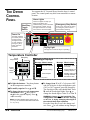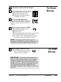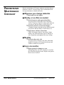
1
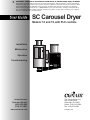
WARNING - Reliance on this Manual Could Result in Severe Bodily Injury or Death!
This manual is out-of-date and is provided only for its technical information, data and capacities. Portions of this manual
detailing procedures or precautions in the operation, inspection, maintenance and repair of the product forming the subject
matter of this manual may be inadequate, inaccurate, and/or incomplete and cannot be used, followed, or relied upon.
Contact Conair at [email protected] or 1-800-654-6661 for more current information, warnings, and materials about
more recent product manuals containing warnings, information, precautions, and procedures that may be more adequate
than those contained in this out-of-date manual.
SC Carousel Dryer
Models 7.5 and 15, with PLC controls
Installation
Maintenance
Operation
Troubleshooting
180
180
Instant Access
Parts and Service
(800) 458-1960
(814) 437-6861
www.conairnet.com
The Conair Group, Inc.
One Conair Drive
Pittsburgh, PA 15202
Phone: (412) 312-6000
Fax: (412)-312-6001
UGD001/1196
Please record your
equipment’s model
and serial number(s)
and the date you
receive it in the
spaces provided.
It’s a good idea to record the model and serial number(s) of
your equipment and the date you received it in the User
Guide. Our service department uses this information, along
with the manual number, to provide help for the specific
equipment you installed.
Please keep this User Guide and all manuals, engineering
prints and parts lists together for documentation of your
equipment.
Date:
Manual number: UGD001/1196
Serial number(s):
Model number(s):
DISCLAIMER: The Conair Group, Inc., shall not be liable for errors
contained in this User Guide or for incidental, consequential damages in connection with the furnishing, performance or use of this
information. Conair makes no warranty of any kind with regard to
this information, including, but not limited to the implied warranties
of merchantability and fitness for a particular purpose.
Copyright 1996
THE CONAIR GROUP, INC.
All rights reserved
INTRODUCTION .........................................1-1
Purpose of the user guide ......................................................1-2
How the guide is organized ...................................................1-2
Your responsibilities as a user .............................................. 1-2
ATTENTION: Read this so no one gets hurt ........................1-3
How to use the lockout device...............................................1-4
TABLE OF
CONTENTS
DESCRIPTION .......................................... 2-1
What is the SC dryer?............................................................2-2
Typical applications ...............................................................2-2
How it works..........................................................................2-3
Specifications: SC dryer ........................................................2-4
Specifications: CH10 and CH14 hoppers..............................2-5
Specifications: CH16 hoppers ...............................................2-6
INSTALLATION ......................................... 3–1
Unpacking the boxes..............................................................3-2
Preparing for installation .......................................................3-3
Mounting dryer and hopper on a processing machine ..........3-4
Mounting dryer on a floor stand; hopper on the throat.........3-6
Connecting air and water hoses.............................................3-8
Connecting the RTD probe ....................................................3-9
Connecting the main power ...................................................3-9
Testing the installation.........................................................3-10
OPERATION ............................................ 4–1
The dryer control panel .........................................................4-2
The temperature controller ....................................................4-2
To start drying........................................................................4-3
To stop drying ........................................................................4-3
MAINTENANCE ........................................ 5–1
Preventative maintenance checklist .......................................5-2
Cleaning the hopper...............................................................5-3
Cleaning the process filter .....................................................5-4
Cleaning the regeneration filter .............................................5-4
Cleaning the return air screen................................................5-4
Cleaning the aftercooler coils ................................................5-5
Inspect hoses and gaskets ......................................................5-5
UGD001/1196
SC Carousel Dehumidifying Dryer
i
TABLE OF
CONTENTS
TROUBLESHOOTING................................. 6–1
Before beginning....................................................................6-2
A few words of caution .........................................................6-2
DIAGNOSTICS
Understanding the alarm lights..............................................6-3
Shut down alarms ..................................................................6-4
Alarm A.................................................................6-4
Alarm B.................................................................6-6
Alarm C ................................................................6-8
Passive alarms........................................................................6-8
Alarm D ................................................................6-8
Alarm E...............................................................6-10
Alarm F...............................................................6-12
ALARMS
ALARMS
ALARMS
ALARMS
ALARMS
ALARMS
REPAIR
Replacing fuses......................................................................6-5
Checking switches and relays................................................6-5
Replacing heater elements .....................................................6-7
Adjusting the limit switch .....................................................6-9
Adding an aftercooler ..........................................................6-11
Replacing desiccant tanks....................................................6-13
APPENDIX
Service/Warranty information .......................... Appendix A
Slide gate mounting options ............................ Appendix B
If you purchased an SC dryer option, instructions
can be found in the appendix.
Option: Auto Start Timer ................................... Appendix C
Option: Dew point Monitor ............................... Appendix D
Option: Remote Control Bracket ....................... Appendix E
PARTS/DIAGRAMS
This section has been provided for you to
store spare parts lists and diagrams.
ii
SC Carousel Dehumidifying Dryer
UGD001/1196
INTRODUCTION
● Purpose of the User Guide ........1-2
● How the guide is organized .......1-2
● Your responsibilities as a user ..1-2
● ATTENTION: Read this so
no one gets hurt ................... 1-3
● How to use the lockout device .1-4
UGD001/1196
SC Carousel Dehumidifying Dryer
1-1
PURPOSE OF
THE USER
GUIDE
This User Guide describes the Conair SC series of carousel
dehumidifying dryers and explains step-by-step how to install,
operate, maintain and repair this equipment.
HOW THE
GUIDE IS
ORGANIZED
Symbols have been used to help organize the User Guide and
call your attention to important information regarding safe
installation and operation.
YOUR
RESPONSIBILITY
AS A USER
Before installing this product, please take a few moments to
read the User Guide and review the diagrams and safety information in the instruction packet. You also should review manuals covering associated equipment in your system. This
review won’t take long, and it could save you valuable installation and operating time later.
!
Symbols within triangles warn of conditions that could
be hazardous to users or could damage equipment.
Read and take precautions before proceeding.
1
Numbers within shaded squares indicate tasks or steps
to be performed by the user.
◆
A diamond indicates the equipment’s response to an
action performed by the user.
❒
●
An open box marks items in a checklist.
A shaded circle marks items in a list.
You must be familiar with all safety procedures concerning
installation, operation and maintenance of this equipment.
Responsible safety procedures include:
● Thorough review of this User Guide, paying particular
attention to hazard warnings, appendices and related diagrams.
● Thorough review of the equipment itself, with careful
attention to voltage sources, intended use and warning
labels.
● Thorough review of instruction manuals for associated
equipment.
● Step-by-step adherence to instructions outlined in this
User Guide.
1-2
INTRODUCTION
SC Carousel Dehumidifying Dryer
UGD001/1196
We design equipment with the user’s safety in mind. You can
avoid the potential hazards identified on this machine by following the procedures outlined below and elsewhere in the
User Guide.
!
ATTENTION:
READ THIS
SO NO
ONE GETS HURT
CAUTION: High voltage
This equipment is powered by threephase main voltage. Always disconnect
and lock out the main power source
before servicing. To help you, we’ve
equipped the dryer with a lockable, electrical disconnect device. You are responsible for developing a lockout procedure.
CAUTION: Hot Surfaces
Always protect yourself from hot surfaces
inside the dryer and hopper. Also exercise
caution around certain exterior surfaces
that can reach temperatures of 180˚ to
200˚ F (82˚ to 93˚ C). These include the
hopper door frame, the exterior of an
uninsulated hopper, the return air hose
and the dryer’s process filter housing and
moisture exhaust outlet.
WARNING: Do not place
aerosol, compressed gas or
flammable materials on or near
this equipment.
The hot temperatures associated with
the drying process may cause aerosols
or other flammable materials placed on
the dryer or hopper to explode.
UGD001/1196
SC Carousel Dehumidifying Dryer
INTRODUCTION
1-3
HOW TO USE
THE LOCKOUT
DEVICE
CAUTION: Before performing maintenance
or repairs on this product, you should disconnect
and lock out electrical power sources to prevent
injury from unexpected energization or start-up. A
lockable device has been provided to isolate this
product from potentially hazardous electricity.
Lockout is the preferred method of isolating machines or
equipment from energy sources. Your Conair product is
equipped with the lockout device pictured below. To use the
lockout device:
1
2
Stop or turn off the equipment.
Isolate the equipment from
electrical power.
I
Turn the rotary disconnect
switch to Off, or O position.
3
Secure the device with an
assigned lock or tag.
O
4
The equipment is now locked out.
! WARNING: Before removing lockout
devices and returning switches to the ON position,
make sure that all personnel are clear of the
machine, tools have been removed and all safety
guards reinstalled.
1-4
INTRODUCTION
IMS0001/0795
DESCRIPTION
● What is the SC Carousel Dryer? .. 2-2
● Typical applications ...................... 2-2
● How it works ................................. 2-3
● Specifications: SC Dryer ............. 2-4
● Specifications: CH10/14 hopper.. 2-5
● Specifications: CH16 hopper ...... 2-6
UGD001/1196
SC Carousel Dehumidifying Dryer
2-1
WHAT IS THE
SC CAROUSEL
DRYER?
The SC Carousel Dehumidifying Dryer produces hot, low-dew
point air that removes moisture from hygroscopic plastics. The
dryer pulls warm, moist air from a drying hopper and pumps it
through dehumidifying desiccant. The dryer then heats the air
to the drying temperature you selected and circulates it through
the material in the hopper.
The dryer’s three-tank, closed-loop design ensures a continuous
supply of hot, dehumidified air while preventing contamination
from moisture in the plant.
TYPICAL
APPLICATIONS
180
180
180
180
The small SC dryer can
be mounted beside the
hopper on the throat of a
processing machine, or
on a floor stand. Two
mobile floor stand designs
are available.
180
180
The SC dryer can be used successfully in applications that require:
● A contamination-free drying environment.
● Drying temperatures of 150˚ to 375˚ F
(66˚ to 191˚ C).
● Throughput rates of 15 to 28 pounds (6.8 to
12.7 kilograms) per hour.
● Dew points of -40˚ F (-40˚C).
If you are drying material at temperatures over 250˚ F (121˚C),
you will need the high-temperature package that includes an
aftercooler.
2-2
DESCRIPTION
SC Carousel Dehumidifying Dryer
UGD001/1196
The SC Carousel Dryer achieves continuous, closed loop drying by passing air simultaneously through two heaters and
three tanks of molecular sieve desiccant.
HOW IT WORKS
The Process (Drying) Cycle
The process blower pulls moist air from the top
of the drying hopper. The air passes through the
process filter and aftercooler into the dryer’s
desiccant tank, where moisture is removed. The
now-dry air moves through the process heater,
where it is heated to the drying temperature
selected by the operator. The hot, dry air is delivered to the hopper, where a spreader cone evenly
distributes the air through the material.
The Cooling Cycle
A regenerated desiccant tank must
be cooled to the drying temperature
range before it is moved back into
the process cycle. The process
blower pushes a small amount of air
through the regenerated desiccant
tank. The cooling air then passes
through the aftercooler and repeats
the circuit.
UGD001/1196
SC Carousel Dehumidifying Dryer
The Carousel
The carousel indexes
every 15 minutes,
moving a desiccant
tank through three
cycles in 45 minutes.
The Regeneration Cycle
The regeneration blower pulls air
through the regeneration filter into the
dryer’s regeneration heater. The air is
heated to 425˚ F (218˚ C) before it is
pushed into the “wet” desiccant tank.
The hot air purges moisture from the
desiccant. The moist air is blown out
the exhaust at the back of the dryer.
DESCRIPTION
2-3
SPECIFICATIONS: SC CAROUSEL DRYER
Standard model
Economy model
C
D
,
,
F
E
A
B
Model
,,
C
D
A
B
SC7.5
SC15
SC30
SC60
20.5 (54.6)
25 (63.5)
27.5 (69.9)
12.25 (31.1)
6.5 (15.2)
3.5 (8.9)
125 (56.8)
21.5 (54.6)
25 (63.5)
30.5 (77.5)
12.25 (31.1)
6.5 (15.2)
3.5 (8.9)
140 (63.5)
26.5 (67.3)
28.25 (71.8)
36.12 (91.7)
14.25 (36.2)
6.5 (16.5)
3.5 (8.9)
185 (83.9)
30.5 (77.5)
30.0 (76.2)
43 (109.2)
14.25 (36.2)
6.5 (16.5)
3.5 (8.9)
240 (108.8)
Dimensions
inches (cm)
A
B
C
D*
E*
F*
Weight lbs (Kg)
Voltage / Total Amps
208 V/3 phase/60 hz
240 V/3 phase/60 hz
380 V/3 phase/50 hz
415 V/3 phase/50 hz
480 V/3 phase/60 hz
575 V/3 phase/60 hz
11 A
9.6 A
5.6 A
5.4 A
4.0 A
4.3 A
Total Kilowatts 2.8 KW (159 BTU/Min)
Air Flow ft3/min. (m3/min.) 7.5 (0.21)
Drying Temperature
Dewpoint
10 A
15.2 A
8.7 A
13.2 A
5.5 A
8.2 A
5A
7.5 A
4.3 A
6.7 A
3.7 A
5.9 A
3.7 KW (208 BTU/Min)
5.05 KW (287 BTU/Min)
15 (0.4)
30 (0.85)
ALL MODELS
150 -375˚F (66-191˚C)
ALL MODELS
-40˚F (-40˚C)
25 A
24 A
14.7 A
14.0 A
12.8 A
10.7 A
9.1 KW (517 BTU/Min)
60 (1.7)
*Not applicable on economy models
SPECIFICATIONS: MAIN POWER SUPPLY WIRE
The main power wire must be:
● Grounded and secured with a strain relief.
● Correctly sized for the current drawn.
Allowable ampacities of Copper Conductors
U.S.A.
Conductor
Size AWG
14
12
10
8
Canada
75˚C insulation
90˚C insulation
30˚C ambient air
40˚C ambient air
Maximum Full Load Amps
15
20
30
43
13
17
27
47
European Community
Ground wire
Size AWG
14
12
10
10
70˚C insulation; 40˚C ambient air
Conductor
Maximum
2
Full Load Amps
Size mm
2,5
4
6
10
16
23
29
40
NOTE: Local or regional electrical guidelines may have specifications that differ from the above national codes. You should comply with the codes for your area.
2-4
DESCRIPTION
SC Carousel Dehumidifying Dryer
UGD001/1196
SPECIFICATIONS:
A
D
CH10 DRYING HOPPER
Model
C
CH10-1
Insulated
B
CH10-1.5
Uninsulated
Insulated
Uninsulated
12.5 (31.8)
48 (121.9)
54 (137.2)
6 (15.2)
7.5 (19.1)
31 (78.7)
10 (25.4)
48 (121.9)
54 (137.2)
6 (15.2)
7.5 (19.1)
29.75 (75.6)
50 (22.7)
30 (13.6)
1.5 (42.5)
35 (15.8)
30 (13.6)
1.5 (42.5)
Dimensions
inches (CM)
E
F
Insulated hopper
A
12.5 (31.8)
B
33.5 (85.1)
C
39.5 (100.3)
D (optional flange) 6 (15.2)
E
7.5 (19.1)
F
31 (78.7)
10 (25.4)
33.5 (85.1)
39.5 (100.3)
6 (15.2)
7.5 (19.1)
29.75 (75.6)
A
Hopper weight lbs (Kg) 40 (18.1)
Mounting frame weight
D
Volume Ft
3
(liters)
DISCHARGE
ASSEMBLY
C
B
25 (11.3)
30 (13.6)
1 (28.3)
30 (13.6)
1 (28.3)
7/16 inches
(1.11 cm)
diameter
7/16 inches
(1.11 cm)
diameter
6 inches
(15.24 cm)
square
2 inches
(5.08 cm)
diameter
1 inch
(2.54 cm)
diameter
5 inches
(12.7 cm)
square
E
F
Uninsulated hopper
4 inches
(10.16 cm)
square
3 inches
(7.62 cm)
square
standard
optional
SPECIFICATIONS:
A
D
CH14 DRYING HOPPER
Model
C
CH14-2
Insulated
Uninsulated
CH14-3
Insulated
Uninsulated
17 (43.2)
48 (121.9)
54 (137.2)
6 (15.2)
6.5 (16.5)
36.75 (93.4)
14 (35.6)
48 (121.9)
54 (137.2)
6 (15.2)
6.5 (16.5)
35.25 (89.5)
80 (36.3)
35 (15.9)
3 (85)
50 (22.7)
35 (15.9)
3 (85)
B
Dimensions
inches (CM)
E
F
Insulated hopper
A
B
C
D
E
F
17 (43.2)
37 (94.0)
43 (109.2)
6 (15.2)
6.5 (16.5)
36.75 (93.4)
14 (35.6)
37 (94.0)
43 (109.2)
6 (15.2)
6.5 (16.5)
35.25 (89.5)
A
Hopper weight lbs (Kg) 70 (31.7)
D
Mounting frame weight
Volume Ft
3
(liters)
DISCHARGE
ASSEMBLY
C
B
E
F
Uninsulated hopper
UGD001/1196
SC Carousel Dehumidifying Dryer
40 (18.1)
35 (15.9)
2 (56.6)
35 (15.9)
2 (56.6)
7/16 inches
(1.11 cm)
diameter
7/16 inches
(1.11 cm)
diameter
6 inches
(15.24 cm)
square
2 inches
(5.08 cm)
diameter
5 inches
(12.7 cm)
square
standard
4 inches
(10.16 cm)
square
1 inch
(2.54 cm)
diameter
3 inches
(7.62 cm)
square
optional
DESCRIPTION
2-5
INSTALLATION
● Unpacking the boxes ................... 3-2
● Preparing for installation ............ 3-3
● Mounting dryer and hopper
on a processing machine ....... 3-4
● Mounting dryer on a floor stand;
hopper on the throat ............... 3-6
● Connecting air and water hoses.. 3-8
● Connecting the RTD probe ......... 3-9
● Connecting the main power ....... 3-9
● Testing the installation ............... 3-10
UGD001/1196
SC Carousel Dehumidifying Dryer
3-1
UNPACKING
THE BOXES
The SC carousel dryer comes in one to four boxes, depending
on the models and options ordered. The boxes should include:
RTD probe
Two lengths of
flexible hose
Drying
hopper
SC Dryer
(one insulated)
Hopper
base plate
Discharge
assembly
180
180
(small or large)
Hopper
slide gate
Dryer/hopper
Support frame
(optional)
Mounting
adapter
(optional)
Floor stand
(optional)
Mounting Hardware:
Floor stand option:
❒ four 3/8-16 self-locking bolts
❒ four 3/8-16 bolts with lock
washers
❒ three 1/4-20 self-locking bolts
❒ four hose clamps
Support frame option:
❒
❒
❒
❒
eight 3/8-16 self-locking bolts
three 1/4-20 self-locking bolts
four 3/8-16 countersunk bolts
four hose clamps
NOTE: You must mount the
dryer on a floor stand, If
your processing machine
throat opening is 1 inch
(2.54 cm) diameter or
smaller and requires a
3x3 inch (7.6x7.6 cm) or
smaller bolt pattern.
3-2
INSTALLATION
1
Carefully remove the dryer and components
2
Remove all packing material, protective paper, tape
3
Carefully inspect all components to make sure no
4
Take a moment to record serial numbers and
electrical power specifications in the blanks provided on
the back of the the User Guide’s title page. The information will be helpful if you ever need service or parts.
5
You are now ready to begin installation.
from their shipping containers, and set upright.
and plastic.
damage occurred during shipping, and that you have all
the necessary hardware.
Follow the preparation steps on the next page, then
choose one of the three mounting options:
● Dryer and hopper on a mobile floor stand. (Go to
page 3-8 after completing first preparation step.)
● Dryer and hopper on the processing machine throat.
● Dryer on a floor stand; hopper on the throat.
SC Carousel Dehumidifying Dryer
UGD001/1196
PREPARING FOR
INSTALLATION
The SC Dryer is easy to install, if you plan the location and
prepare the mounting area properly.
1
Make sure the mounting area provides:
❒ A grounded, three-phase power source supplying
the correct current for your dryer model. Check the
dryer’s serial tag for the correct amps, voltage and cycles.
Field wiring should be completed by qualified personnel
to the planned location for the dryer. All electrical wiring
should comply with your region’s electrical codes.
❒ A source of water, if you have an aftercooler.
The SC dryer’s optional aftercooler can use tower, city or
chiller water with temperatures up to 90˚ F (32˚ C). Pipe
should be run to the planned dryer location. Use flexible
hose to connect the water pipes to the aftercooler.
❒ Minimum clearance for safe
operation and maintenance.
We recommend at least 25 inches
(63.5 cm) clearance above the dryer for
removing the carousel housing. You
should maintain 24 inches (61 cm)
4 inches
clearance on at least three sides of the (10.2 cm)
dryer. If the dryer is mounted with a
hopper on a processing machine throat,
clearance between the dryer and hopper can be 4 inches (10.2 cm).
24 inches
(61 cm)
,,
Top
24 inches
(61 cm)
Control
24 inches
(61 cm)
❒ A mounting surface that will support the weight of
the dryer, support frame and a fully-loaded hopper, or just
the fully-loaded hopper. See the specifications tables for
weights and volumes.
❒ Material and conveying lines installed. If you plan
to use vacuum or compressed air loaders to fill the hopper, install conveying lines to the drying hopper location.
2
Drill and tap mounting holes or make adapter.
Available discharge assemblies and slide gates fit mounting surfaces with these bolt patterns and diameters:
7/16 inches
(1.11 cm)
diameter
7/16 inches
(1.11 cm)
diameter
6 inches
(15.24 cm)
square
2 inches
(5.08 cm)
diameter
5 inches
(12.7 cm)
square
UGD001/1196
If your mounting surface does not match
the standard bolt patterns available, you
will need an adapter.
You can make an
adapter using the
dimensions provided
or purchase one from
Conair.
4 inches
(10.16 cm)
square
1 inch
(2.54 cm)
diameter
SC Carousel Dehumidifying Dryer
3 inches
(7.62 cm)
square
INSTALLATION
3-3
MOUNTING
DRYER AND
HOPPER ON A
PROCESSING
MACHINE
! WARNING: You are responsible for the
structural integrity of this installation.
We recommend that you:
● Use bolts no smaller than 3/8 inch (M 10)
when mounting the hopper/dryer combination
to the throat of a processing machine.
● Do not mount the hopper/dryer combination
on a plate that swings away or slides away
from the processing machine throat. Either
remove the swing or slide plate, or mount the
dryer on a floor stand.
Drying
hopper
SC Dryer
Hopper
base plate
180
180
Hopper
slide gate
Support frame /
Discharge assembly
Mounting
adapter
(optional)
Tools for installation:
❒ 5/32” Allen wrench
❒ Phillips screwdriver
❒ Flathead screwdriver
❒ 9/16” and 3/8” wrench
❒ Hoist and strap
NOTE: You must mount the
dryer on a floor stand, If
your processing machine
throat requires the small discharge assembly or a
mounting plate with less
than a 3x3 inch (7.6x7.6
cm) bolt pattern and 1-inch
(2.54 cm) diameter opening.
3-4
INSTALLATION
The dryer and hopper mounts on a special bracket that bolts to
the throat of the processing machine, as pictured above.
! CAUTION: To prevent accident and injury,
lift the empty hopper onto the throat of the
processing machine using a hoist and the
lifting lugs provided. After the hopper is
mounted, then lift the dryer onto the support
frame using a hoist and strap.
SC Carousel Dehumidifying Dryer
UGD001/1196
MOUNTING
DRYER AND
HOPPER ON A
PROCESSING
MACHINE
Remove the hopper base plate and bolts from the bag
attached to the mounting bracket/ discharge assembly.
1
Place the aluminum ring on the
mounting bracket / discharge assembly.
2
Bolt the base plate to
the hopper bottom.
Use the four 3/8-16 countersunk bolts provided.
3
Place the slide gate on the
processing machine throat.
Position the slide gate so that its
bolt holes line up with the holes that
were drilled in the throat. If hole patterns
do not match, bolt a mounting adapter
between the throat and slide gate.
4
5
Bolt the support frame and discharge to the throat.
Using four 3/8-16 (M 10) self-locking
bolts, fasten the support frame, discharge
and slide gate to the throat. The bolts
must be long enough to reach at
least 1/2 inch (1.25 cm) into the
mounting adapter or processing
machine throat after passing
through the discharge assembly,
support frame and slide gate.
5
2
4
3
Lift and bolt the hopper to the support frame
and discharge assembly.
Lift the hopper with a hoist, using the lug nuts provided.
Align the bolt holes and fasten, using the four 3/8-16
self-locking bolts provided.
6
Lift the dryer onto the support frame.
Lift using a hoist and strap.
Align the three bolt holes on
the bottom of the dryer with
the three bolt holes on the
top of the support frame.
Make sure the acorn nuts on
the bottom of the dryer fit in
the holes on the support
form. Fasten the dryer to the
frame with 1/4-20 bolts.
UGD001/1196
SC Carousel Dehumidifying Dryer
NOTE: You may position
the drain port and slide
gate to face the direction
that best suits your maintenance and operation routines. The slide gate also
can be mounted between
the hopper and discharge
assembly. See “Slide Gate
Mounting Options” in the
Appendix.
180
180
INSTALLATION
3-5
MOUNTING THE
DRYER ON A
FLOOR STAND;
HOPPER ON THE
THROAT
WARNING: You are responsible for the
structural integrity of this installation.
We recommend that you:
● Use bolts no smaller than 3/8 inch (M 10)
to mount the hopper on the throat of a processing machine.
!
Drying
hopper
SC Dryer
Discharge
assembly
Hopper
slide gate
Mounting
adapter
(optional)
180
180
Tools for installation:
❒ 5/32” Allen wrench
❒ 3/8” and 9/16” wrench
❒ Phillips screwdriver
❒ Flathead screwdriver
❒ Hoist and strap
Floor stand
The hopper bolts to the throat of the processing machine, as
pictured above. The dryer bolts to a mobile floor stand.
! CAUTION: To prevent accident and injury,
lift the empty hopper onto the throat of the
processing machine using a hoist and the
lifting lugs provided. Lift the dryer onto the
floor stand using a hoist and strap.
3-6
INSTALLATION
SC Carousel Dehumidifying Dryer
UGD001/1196
MOUNTING
THE HOPPER
You need to assemble the hopper and discharge before
mounting the hopper on the throat of the processing
machine.
1
Bolt the discharge to the hopper bottom.
2
Place the slide gate on the throat of the
processing machine.
Use the four 3/8-16 bolts with lock washers provided.
Position the slide gate so that its
bolt holes line up with the holes
that were drilled in the throat. If
hole patterns do not match, bolt a
mounting adapter between the throat and
slide gate.
3
4
NOTE: You may
1
Lift the hopper onto the throat.
Lift the hopper with a hoist, using the
lifting lugs provided. Make
sure you align the bolt holes in
the throat with the bolt holes
on the slide gate and discharge
assembly.
4
2
Bolt the hopper to the
throat of the machine.
position the drain
port and slide gate
to face the direction
that best suits your
maintenance and
operation routines.
The slide gate also
can be mounted
between the hopper
and discharge
assembly. See “Slide
Gate Mounting
Options” in the
Appendix.
Using four 3/8-16 (M 10) self-locking bolts, fasten the
support frame, discharge and slide gate to the throat. The
bolts must be long enough to reach at least 1/2 inch (1.25
cm) into the mounting adapter or processing machine
throat, after passing through the discharge and slide gate.
1
Lift the dryer onto the
floor stand, and bolt.
MOUNTING
THE DRYER
Lift using a hoist and strap.
2
3
Align the three bolt holes
on the bottom of the dryer with
the three bolts holes on the top of
the floor stand.
180
180
Bolt the dryer to the stand
using the three 1/4-20 bolts provided.
UGD001/1196
SC Carousel Dehumidifying Dryer
INSTALLATION
3-7
CONNECTING
AIR HOSES
Using the two flexible hoses provided, connect the inlets and
outlets of the drying hopper to the dryer. If you have mounted
the dryer on a floor stand, make sure the dryer is located no
more than 5 feet (1.5 m) from the hopper to reduce heat loss.
1
Attach the 2 1/2-inch (6.4 cm)
hose to the return air inlet in the
base of the aftercooler housing and
to the return air outlet at the top of
the hopper.
2
Attach the 2-inch
(5.1 cm) insulated
hose to the delivery air
outlet in the base of the
dryer and to the hopper’s delivery air inlet.
3
NOTE: Do not allow
the flexible hoses to
kink or crimp.
CONNECTING
WATER HOSES
Secure hoses with clamps.
The hose clamp should be
secured at least 1/4 inch (.64 cm)
from the end of the inlet or outlet
tube.
The optional aftercooler requires a source of cooling water
and a discharge or return line. The water source should provide 3 gallons (11.36 liters) per minute at temperatures up to
90˚ F (32˚ C).
1/2 inch NPT female
couplings. If a manual
shut off valve is used, it
should be mounted on
the inlet line.
1
Connect the cooler inlet to the
water source.
2
Connect the cooler outlet to a
discharge or return line.
TIP: Make the connections with
flexible hose at least 14 inches
(35.5 cm) long. This allows you to
easily remove the cooler coils for
cleaning.
3-8
INSTALLATION
SC Carousel Dehumidifying Dryer
UGD001/1196
The RTD probe monitors the temperature of the drying air as
it enters the hopper. If the probe is not installed correctly, temperature readings will be inaccurate.
1
Insert the probe in
the delivery air inlet at
CONNECTING
THE RTD
PROBE
the top of the hopper. The
end of the probe must not
touch the walls of the inlet.
Tighten the nuts to lock the
probe in place.
2
Plug the probe’s cable
into the dryer control
box. Coil any excess cable
and secure with a wire tie.
CAUTION: Always disconnect
and lock out the main power sources
before making electrical connections.
Electrical connections should be
made only by qualified personnel.
1
CONNECTING
THE MAIN
POWER
Open the dryer’s electrical enclosure.
Turn the disconnect dial on the dryer door to the
Off position. Lock out the main power. Turn the
captive screw, and swing the door open.
2
O
Insert the main
power wire through
the knockout in the side
of the enclosure. Secure
the wire with a rubber
compression fitting or
strain relief.
3
Connect the power
wires to the three terminals at the top of the
disconnect holder.
4
UGD001/1196
IMPORTANT: Always
refer to the wiring diagrams
that came with your dryer
before making electrical
connections. The diagrams
show the minimum size
main power cable required
for your dryer, and the
most accurate electrical
component information.
Connect the ground wire to either
grounding point shown in the diagram.
SC Carousel Dehumidifying Dryer
INSTALLATION
3-9
MOUNTING A
LOADER ON
THE HOPPER
If you have a Conair loader or vacuum
receiver, you can use the flange and
mounting clips provided on the top of
the hopper. Refer to the manuals that
came with your receiver or loader for
detailed installation instructions.
TESTING THE
INSTALLATION
You have completed the installation. Now it’s time to make
sure everything works. You should perform this test with no
material in the hopper.
1
2
Make sure there is no material in the hopper.
If you have mounted a loader or vacuum receiver on the
hopper, disconnect the material inlet hose at the source.
Turn on the main power to the dryer.
Make sure the dryer’s disconnect dial and
Emergency Stop button are in the on position.
If everything is installed correctly:
◆ The dryer control’s white power-on light turns on.
◆ The temperature controller display turns on.
◆ Temperature controller runs a self-diagnostic test.
The following sequence will display briefly:
I
TEST
OP
AL
1111
SET TEMPERATURE
3
4
8888
OP
AL
8888
SET TEMPERATURE
3013
OP
AL
SET TEMPERATURE
Set the drying temperature.
Press the up or down arrow on the temperature controller
until the setpoint temperature you want appears in the
lower display.
Flip the toggle switch to START.
START
If everything is installed correctly:
◆ The green drying light turns on.
◆ The process and regeneration blowers turn on.
◆ The process and regeneration heaters turn on.
◆ If the desiccant tanks aren’t in their correct position,
the carousel will turn clockwise and stop in the correct position.
STOP
3-10
INSTALLATION
SC Carousel Dehumidifying Dryer
UGD001/1196
5
6
Check for proper air flow.
Remove the delivery air hose on
the dryer. Hold your hand near
the outlet with the dryer on. You
should feel air blowing out of the
dryer.
Moisture
exhaust
Delivery
air outlet
Flip the toggle switch to STOP to
turn off the dryer.
If everything is installed correctly:
◆ The green drying light stays on for
two minutes.
◆ The blowers continue running for
two minutes to cool the heaters.
7
START
STOP
The test is over.
If the dryer performed the normal operating sequences
as outlined, you can begin operation. If it did not, refer to
the troubleshooting section of the User Guide.
UGD001/1196
SC Carousel Dehumidifying Dryer
INSTALLATION
3-11
UGD001/1196
SC Carousel Dehumidifying Dryer
OPERATION
● The dryer control panel .............. 4-2
● The temperature controller ........ 4-2
● To start drying ............................. 4-3
● To stop drying ............................. 4-3
UGD001/1196
SC Carousel Dehumidifying Dryer
4-1
THE DRYER
CONTROL
PANEL
You operate the SC Carousel Dryer from the dryer’s control
panel. The control panel may have been mounted in a remote
location.
Alarm Lights
These four lights can help you
diagnose problems. The
Troubleshooting section describes
their functions. NOTE: The air
flow light should turn on briefly
each time the carousel rotates.
Start/Stop
Toggle
Switch
Power On
OPERATION
This light indicates
the control panel is
receiving power.
The light remains
on even when the
Emergency Stop
button has been
activated.
Push to turn off the dryer during
an emergency. Pull to restore
power before restarting.
CONAIR
FRANKLIN
ALARMS
188
EMERGENCY
START
188
POWER
Emergency Stop Button
!
SET TEMPERATURE
STOP
SHUT
DOWN
DRYING
TEMP.
REGEN.
STOP
AIR
FLOW
Drying Light
This light is on when the dryer is operating.
Temperature Controller
Setup Key
Setpoint
Actual
temperature
Output
active
Alarm
active
188
OP
AL
188
Message Displays
Message What it means
TEST
Self-test activated
SnSr
RTD sensor failed
or is loose
8888
Self-test working
----
Air temperature not
reaching setpoint
1111
8888
---SET TEMPERATURE
Message What it means
LP.br
Alarm setpoint
AL.SP
----
FAIL
---SET
is actual temperature
Standby mode. The
message will blink
from SET to OFF.
Decrease Change Increase
function
● To light the buttons: Touch any button
on the temperature controller.
● To modify setpoint: Press ▲ and ▼.
● To change the process air temperature
alarm band: Press until you see
AL.SP in the setpoint display. Press ▲
or ▼ to modify.
NOTE: The alarm band is factory set at ± 20˚ F
(± 11˚ C). Do not set the alarm band lower than
± 5˚ F (± 3˚ C).
4-2
OPERATION
● To change from ˚F to ˚C: Cycle power OFF
and ON. After the 4-digit configuration code
(3013 or 3017) appears, press the Setup Key.
The first digit of the code should blink. Press
▼ until the fourth digit blinks. Press ▲ to
change the fourth digit to 7 for ˚C or 3 for ˚F.
WARNING: Change only the fourth digit. The
configuration code must be 3013 for ˚F drying
or 3017 for ˚C drying. Changing other digits in
the code will harm dryer operation.
Press the Setup Key to save the change and
exit. Press
to exit without saving changes.
SC Carousel Dehumidifying Dryer
UGD001/1196
1
Verify there is material in the hopper.
2
Turn on main power to the dryer.
3
4
TO START
DRYING
◆ The white power light turns on.
◆ Temperature display turns on.
◆ Temperature controller performs
self-diagnostic testing.
I
Set the drying temperature.
Press the up or down arrow on the temperature controller until the setpoint temperature you want appears in the lower
display.
Flip the toggle switch to START.
188
188
SET TEMPERATURE
START
◆ The green drying light turns on.
STOP
◆ Both blowers turn on.
◆ Heaters turn on.
◆ If the desiccant tanks aren’t in their correct position,
the carousel will turn to the correct position.
◆ The yellow air flow alarm light will turn on each
time the desiccant carousel indexes correctly.
NOTE: The drying light will not turn on if the
Emergency Stop button is pushed in. Make sure the
stop button is pulled out before starting the dryer.
1
Flip the toggle switch to STOP.
◆ The drying light stays on and the
blowers continue running for two
minutes to cool the heaters.
START
STOP
TO STOP
DRYING
IMPORTANT: Do not use the Emergency Stop
button to stop the dryer unless it is an emergency.
Using the Emergency Stop button during normal
operation prevents cooling of the heaters and could
damage your dryer. Using the Emergency Stop button to stop the dryer also can trigger the Shut
Down/High Temperature alarm during your next drying cycle.
UGD001/1196
SC Carousel Dehumidifying Dryer
OPERATION
4-3
MAINTENANCE
● Maintenance checklist .................. 5-2
● Cleaning the hopper ..................... 5-3
● Cleaning the process filter ........... 5-4
● Cleaning the regeneration filter ... 5-4
● Cleaning the return air screen .... 5-4
● Cleaning the aftercooler coils ..... 5-5
● Inspect hoses and gaskets ..........5-5
UGD001/1196
SC Carousel Dehumidifying Dryer
5-1
PREVENTATIVE
MAINTENANCE
CHECKLIST
Routine maintenance will ensure optimum operation and performance of the SC Carousel Dryer. We recommend the following maintenance schedule and tasks.
● Whenever you change materials
❒ Drain and clean the hopper.
● Weekly, or as often as needed
❒ Clean the process and regeneration filters.
You may need to clean filters more often than
weekly. Frequency depends on how much material
you process and how dusty or full of fines it is.
❒ Clean the return air screen in the hopper.
Cleaning frequency depends on how much material
you process and how dusty or full of fines it is.
❒ Inspect hoses and hose connections.
Check for damage, kinks or loose hose clamps.
Replace any hoses that show signs of damage or
wear. Reposition and tighten loose hose clamps.
● Monthly
❒ Clean the aftercooler coils.
You may need to clean the coils more often than
monthly. Frequency will depend on the type and
volume of material you process.
● Every six months
❒ Inspect gaskets for damage or wear.
Damaged gaskets can allow moisture to seep into
the closed-loop drying system. Replace any gasket
that is torn or cracked.
5-2
MAINTENANCE
SC Carousel Dehumidifying Dryer
UGD001/1196
CLEANING
THE HOPPER
CAUTION: Hot surfaces.
Always protect yourself from hot surfaces inside and outside the dryer and
drying hopper.
The hopper, spreader cone and discharge assembly should be
cleaned thoroughly between material changes to prevent resin
contamination.
Place a container beneath the hopper’s drain
port to catch the material.
.
1
2
Close the hopper slide gate.
Remove the drain-port plug.
Pull the pin and allow the plug to drop.
2
1
3
After draining material, open the hopper door.
You must lift the safety catch below the
sight glass on the hopper door before
pulling the door handle open.
Safety catch
4
Remove the spreader cone. Reach into the hopper.
Grasp the spreader cone tube, lift up slightly, twist and
then push down to release it. Tilt the cone assembly and
pull it out through the hopper door.
5
Clean the spreader cone and
the inside of the hopper.
6
Repeat the steps in reverse
order to reassemble the hopper before adding
material.
UGD001/1196
SC Carousel Dehumidifying Dryer
MAINTENANCE
5-3
CLEANING THE
PROCESS
FILTER
CLEANING THE
REGENERATION
FILTER
Clogged filters reduce air flow and dryer efficiency. Cleaning frequency depends on how much material you process and how dusty it is.
1
2
MAINTENANCE
2
3
Clean the filter box.
Remove the filter
4
Reassemble by
repeating the steps in
reverse order.
below the process filter box and remove
the box.
by turning the metal
end cap. Clean the
filter. If the filter is
worn, damaged or
clogged, replace it.
Remove the regeneration filter.
Clean the filter. Replace the
Reassemble by
repeating the steps in
reverse order.
A screen in the return air outlet of
the hopper prevents material from
being drawn into the dryer. This
screen may need to be cleaned.
1
Loosen the fasteners at the
base of the return air outlet.
2
Pull the screen and outlet
up out of the hopper.
Clean the screen, then reassem-
3
5-4
Loosen the knob
filter if it is worn, damaged or
hopelessly clogged with dirt, fines
or dust.
3
CLEANING THE
RETURN AIR
SCREEN
1
ble. Make sure the outlet fits snuggly
over the gasket in the hopper.
SC Carousel Dehumidifying Dryer
UGD001/1196
If you have the optional aftercooler, you need
to clean the cooling coils to keep them working
efficiently. Cleaning frequency depends on the
type and amount of material you process.
Release the latches at
1
the top of the aftercooler.
2
Pull the coils out of
CLEANING THE
AFTERCOOLER
COILS
the aftercooler housing.
3
Clean the coils with
high-pressure steam, then
reassemble.
Loose or damaged hoses and gaskets can allow moisture to
seep into the closed-loop drying system.
1
2
Tighten any loose hose clamps.
Replace worn or damaged hoses and gaskets.
INSPECT
HOSES AND
GASKETS
Return air
outlet gasket
Hose clamps
Hose clamps
Aftercooler
gasket
Hopper door
gaskets
UGD001/1196
Process filter
box gasket
SC Carousel Dehumidifying Dryer
MAINTENANCE
5-5
TROUBLESHOOTING
● Before beginning .......................... 6-2
● A few words of caution ................6-2
DIAGNOSTICS
● Understanding the alarm lights... 6-3
● Shut down alarms ........................ 6-4
Alarm A ........................ 6-4
Alarm B ........................ 6-6
Alarm C ........................ 6-8
● Passive alarms ............................ 6-10
Alarm D ........................ 6-10
Alarm E ........................ 6-12
Alarm F ........................ 6-14
ALARMS
ALARMS
ALARMS
ALARMS
ALARMS
ALARMS
REPAIR
● Replacing fuses ........................... 6-5
● Checking switches and relays ....6-5
● Replacing heater elements ......... 6-7
● Adjusting the limit switch ........... 6-9
● Adding an aftercooler ................. 6-11
● Replacing desiccant tanks ..........6-13
UGD001/1196
SC Carousel Dehumidifying Dryer
6-1
BEFORE
BEGINNING
You can avoid most problems by following the recommended
installation and maintenance procedures outlined in this User
Guide. If you do have a problem, this section will help you
determine what caused it and how to fix it.
Before you start pulling side panels off the dryer:
❏ Diagnose causes from the front of the dryer.
You can locate any problem from the front of the dryer.
Swing the electrical
enclosure away
from the front of
the dryer to test
heater elements,
relays and pressure
switches.
Open the electrical
enclosure to check
fuses.
OPERATION
188
SET TEMPERATURE
CONAIR
FRANKLIN
ALARMS
EMERGENCY
START
188
POWER
!
STOP
DRYING
SHUT
DOWN
TEMP.
REGEN.
AIR
FLOW
STOP
Alarm lights indicate
whether the problem
involves air flow,
temperature or
regeneration.
❏ Find the wiring and equipment diagrams that
were shipped with your dryer. These diagrams are
the best reference for correcting a problem. The diagrams
also will note any custom features, such as special wiring
or alarm capabilities, not covered in this User Guide.
A FEW WORDS
OF CAUTION
The standard SC Carousel Dryer is equipped with numerous
safety devices. Do not remove or defeat them. Improper corrective action can lead to hazardous conditions and should
never be attempted to sustain production
!
WARNING: Only qualified service
personnel should examine and correct
problems that require opening the
dryer’s electrical enclosure or using
electrical wires to diagnose the cause.
CAUTION: High voltage.
Always turn off the SC Carousel dryer,
disconnect and lock out the main power
source before troubleshooting or performing repairs.
CAUTION: Hot surfaces.
Always protect yourself from hot surfaces inside and outside of the dryer
and hopper.
6-2
TROUBLESHOOTING
SC Carousel Dehumidifying Dryer
UGD001/1196
The alarm lights on the SC dryer control panel are associated
with the temperature, regeneration and air flow circuits in the
dryer.
A problem can trigger two types of alarms:
OPERATION
188
SET TEMPERATURE
EMERGENCY
START
188
POWER
CONAIR
FRANKLIN
ALARMS
!
STOP
DRYING
ALARMS
SHUT
DOWN
TEMP.
REGEN.
STOP
AIR
FLOW
!
SHUT
DOWN
TEMP.
REGEN.
AIR
FLOW
● Shut Down (red):
The dryer has automatically shut down because
it detected a serious problem that could damage
your material or facility.
● Passive (yellow): The
dryer continues to operate, but warns of a problem that could prevent
correct drying of your
material. If ignored, this
problem could lead to a
shut-down condition.
UNDERSTANDING
THE ALARM
LIGHTS
The lights also can indicate multiple alarms.
When more than one yellow light is on or blinking, more than
one alarm condition occurred. The multiple alarms may indicate problems that occurred at the same time, or a problem
that caused another problem to develop.
If this light is on:
A
!
SHUT
DOWN
Shut
down
alarms
B
E
AIR
FLOW
TEMP.
REGEN.
AIR
FLOW
TEMP.
REGEN.
AIR
FLOW
TEMP.
REGEN.
AIR
FLOW
!
SHUT
DOWN
UGD001/1196
REGEN.
!
SHUT
DOWN
F
TEMP.
!
SHUT
DOWN
Passive
alarms
AIR
FLOW
!
SHUT
DOWN
D
REGEN.
!
SHUT
DOWN
C
TEMP.
TEMP.
REGEN.
AIR
FLOW
Sensors near the process or regeneration heaters detected abnormally high
temperature (solid light) or no air flow
(blinking light).
Temperatures in the process, or drying air, circuit are above or below
the setpoint alarm band.
The desiccant tank carousel did not
rotate or index correctly.
Air returning from the hopper is too
hot for desiccant to work at capacity.
Dew point will suffer. (blinking light)
Temperature sensors indicate the desiccant did not get hot enough to regenerate. (blinking light)
Pressure switches indicate reduced air
flow, probably caused by clogged filters or damaged hoses. (solid light)
SC Carousel Dehumidifying Dryer
TROUBLESHOOTING
6-3
When the red Shut Down alarm lights, the dryer has detected
a problem or combination of problems that could damage your
plant or materials. When a malfunction triggers a Shut Down
alarm:
◆ The dryer automatically shuts off.
◆ The alarm light turns on or blinks on and off.
◆ The temperature controller enters standby mode.
◆ The power light remains on.
SHUT DOWN
ALARMS
Alarm
ALARMS
A
!
SHUT
DOWN
TEMP.
REGEN.
AIR
FLOW
Solid light:
The dryer shut down
because excessive
heat was detected in
the process or regeneration heater box.
Blinking light:
The dryer shut down
because pressure
switches detected no
air flow coming
from the process or
regeneration blower.
WARNING: Only
qualified electrical
service personnel
should examine and
correct problems that
require opening the
dryer’s electrical
enclosure or checking
electrical current to
diagnose the cause of
a problem.
6-4
TROUBLESHOOTING
Possible cause
Solution
Was there a loss of power
or improper shut down
using the Emergency
Stop button?
Flip the toggle switch to
STOP, and then to START. The
power interruption prevented
the heaters from cooling down
after normal operation. This
may have triggered a hightemperature alarm.
Was there an electrical
short in a heater relay?
Disconnect power. Check continuity of the process and
regeneration heater relay outputs. See Checking Switches
and Heater Relays.
Did the regeneration or
process blower fail, causing the air flow pressure
switches to close?
❒ Disconnect power. Check
the blower fuses, and replace if
needed. See Replacing Fuses.
❒ Check motor current against
voltage and amp rating on the
motor nameplate. If currents,
do not match, make sure the
transformer is wired correctly.
If the transformer is wired correctly, replace the blower.
Did an air flow pressure
switch fail?
Disconnect power. Check the
continuity of the pressure
switches. See Checking
Switches and Heater Relays.
Are the air lines blocked
or disconnected?
❑ Straighten crimps. Remove
any objects blocking air flow
through hoses and tubes.
❑ Connect any loose hoses.
❑ Clean or replace clogged
filters.
(If this is the cause, the Air
Flow alarm light should have
turned on first.)
SC Carousel Dehumidifying Dryer
UGD001/1196
1
2
Disconnect power.
Open the electrical enclosure door.
3
Check the fuse.
If necessary, pull the
fuse out and replace
it with a fuse of the
same type and rating.
Fuse Blocks
To locate the appropriate
fuse and replacement
part, refer to the wiring
diagrams that came with
your dryer.
OPERATION
188
1
2
3
SET TEMPERATURE
EMERGENCY
START
188
POWER
CONAIR
FRANKLIN
ALARMS
!
STOP
DRYING
SHUT
DOWN
TEMP.
REGEN.
AIR
FLOW
STOP
Disconnect power.
Swing the electrical enclosure away from the
front of the dryer.
Locate the relay or switch terminals. Refer to the
wiring diagrams that came with your dryer.
4
REPLACING
FUSES
Check continuity using an ohmmeter.
IMPORTANT:
Always refer to the
wiring diagrams that
came with your
dryer to locate specific electrical components. Illustrations
in the User Guide
are intended to be
representative only.
CHECKING
SWITCHES
AND HEATER
RELAYS
Pressure switch
The switch is normally
closed. Replace if resistance is high or infinity.
Regeneration
heater relays
If ohms equal zero or
infinity, replace the relay.
Process heater
relays
If ohms equal zero or
infinity, replace the relay.
UGD001/1196
SC Carousel Dehumidifying Dryer
IMPORTANT:
Always refer to the
wiring diagrams that
came with your
dryer to locate specific electrical components. Illustrations
in the User Guide
are intended to be
representative only.
TROUBLESHOOTING
6-5
SHUT DOWN
ALARMS
When the red Shut Down alarm lights, the dryer has detected
a problem or combination of problems that could damage your
plant or materials. When a malfunction triggers a Shut Down
alarm:
◆ The dryer automatically shuts off.
◆ The alarm light (or lights) turns on.
◆ The temperature controller enters standby mode.
◆ The power light remains on.
Alarm
ALARMS
B
!
SHUT
DOWN
TEMP.
REGEN.
AIR
FLOW
The dryer has shut
down because the
drying, or process
circuit, temperature
is higher or lower
than the setpoint
alarm band allows.
WARNING: Only
qualified electrical service personnel should
examine and correct
problems that require
opening the dryer’s
electrical enclosure or
checking electrical current to diagnose the
cause of a problem.
6-6
TROUBLESHOOTING
Possible cause
Solution
Is the dryer too far from
the hopper to maintain
setpoint temperature of
the air?
The dryer should be no more
than 5 feet (1.5 m) from the
hopper. Move the dryer closer
to the hopper, or insulate the
air delivery hoses.
Is “LP.br” showing in the
temperature controller
display?
The RTD probe has failed or is
no longer connected correctly.
Make sure the probe is inserted
in the delivery air inlet of the
hopper, and that it is plugged
into the control box. If the
connections are correct, the
probe is damaged. Replace it
Is the setpoint alarm
band set too low?
Readjust the alarm band on the
temperature controller. The
alarm band should not be set
lower than ± 5˚ F (± 3˚ C).
Did a process heating element fail?
Check the process heater elements. Disconnect power and
check continuity across the
three process relay outputs to
the heater elements. Ohm readings should be about equal.
Only electrical service personnel should check amperage or
voltage of heater wires. See
Replacing Heater Elements.
Did a process heater
relay fail?
Disconnect power. Check the
continuity of the relay outputs.
If the ohm reading is zero or
near zero, replace the relay.
See Checking Switches and
Heater Relays.
SC Carousel Dehumidifying Dryer
UGD001/1196
Regeneration
Heater
1
Disconnect power and
remove the dryer’s back
panel.
2
Locate the appropriate
heater box.
Detach the heater element
wires from the terminal strip
Process
Heater
2
3
,,
,
,,,
3
above the heater box. Each
element has two wires.
4
,,
,
UGD001/129
Check continuity of the
heater element wires.
Replace any element that
shows an ohm reading of zero
or infinity.
5
6
REPLACING
HEATER
ELEMENTS
5
6
Remove the heater cover.
Remove the insulation.
7
Remove the heater element assembly. Loosen the
Set the insulation aside for
reassembly.
screws and pull the assembly out
of the box.
TIP: For faster repairs,
keep a spare heater
assembly that can be
swapped for the
assembly containing a
faulty element.
8
8
Replace the faulty heater
element(s). Remove the nut
holding the element to the
assembly plate. Pull the element out of the plate. Insert
the wires of a new element
through the plate. Secure the
element with the nut.
9
Reassemble. Follow steps in
reverse order
SC Carousel Dehumidifying Dryer
TROUBLESHOOTING
6-7
SHUT DOWN
ALARMS
When the red Shut Down alarm lights, the dryer has detected
a problem or combination of problems that could damage your
plant or materials. When a malfunction triggers a Shut Down
alarm:
◆ The dryer automatically shuts off.
◆ The alarm light (or lights) turns on.
◆ The temperature controller enters standby mode.
◆ The power light remains on.
Alarm
ALARMS
C
!
SHUT
DOWN
TEMP.
REGEN.
Solution
Is the limit switch adjusted correctly?
Adjust the limit switch so that
it drops into the valley along
the edge of the bed plate. See
Adjusting the Limit Switch.
Did the bed-drive motor
control blow a fuse?
Disconnect power and open
the electrical enclosure. Check
the bed-drive motor fuse, and
replace if necessary. For the
fuse number and appropriate
replacement part, refer to the
wiring diagrams that came
with your dryer.
Is the bed-drive motor
damaged?
Check the electrical connections to the motor. If the fuses
and the connections are in
working order, the motor is
damaged. Replace it.
AIR
FLOW
The dryer shut down
because the desiccant tank carousel
did not rotate from
one position to the
next within the correct time.
6-8
Possible cause
TROUBLESHOOTING
SC Carousel Dehumidifying Dryer
UGD001/1196
Carousel
cover
ADJUSTING THE
LIMIT SWITCH
1 Stop the dryer.
Disconnect and lockout
the main power.
180
180
3
4
5
6
2 Remove the carousel
cover.
Loosen the screw on the limit switch bracket.
Slide the bracket left or right to
position the limit switch so that its small
roller drops into the valley on the bed
plate. The roller should not hit the stationary bottom plate.
Test for correct indexing of the carousel.
Restore main power to the dryer. Hold the limit switch out
of the valley on the carousel bed plate while you flip the
toggle switch to START. Once the bed plate starts turning,
release the switch.
If everything is adjusted correctly:
◆ The carousel bed turns.
◆ When the limit switch reaches the next valley in the
bed plate, the carousel should stop turning.
Reset the desiccant carousel.
Continue indexing until the desiccant tanks return to the
positions they were in when the dryer shut down.
UGD001/1196
SC Carousel Dehumidifying Dryer
TROUBLESHOOTING
6-9
PASSIVE
ALARMS
When a yellow “passive” alarm lights, the dryer has detected a
problem that could prevent correct drying of your material.
When a malfunction triggers a passive alarm:
◆ The alarm light (or lights) turns on.
◆ The dryer continues to operate.
Alarm
Possible cause
Solution
Does the drying hopper
contain enough material?
Verify that your material supply system is working. Refer to
the manuals for your conveying system, if necessary.
Are you drying with high
heat or low throughputs?
You may need an aftercooler if
you are drying at temperatures
over 250˚ F (121˚C), or if you
are drying small amounts of
material. An amount less than
50% of the dryer’s rated capacity is considered small.
See Adding an Aftercooler. If
you have an aftercooler, go to
the next step.
Is water flowing to your
aftercooler?
Turn on the water supply, or
fix the problem that prevents
water from flowing through the
aftercooler. The water flow
must equal at least 3 gallons
(11.36 liters) per minute at 90˚
F (32˚ C).
Are the aftercooler coils
dirty?
Clean the aftercooler coils.
See Maintenance: Cleaning
the Aftercooler Coils.
ALARMS
D
!
SHUT
DOWN
TEMP.
REGEN.
AIR
FLOW
Dew point will suffer because the air
returning from the
hopper is too hot for
the desiccant to
work at capacity.
The return air sensor
has been set to alarm
at temperatures over
130˚ F (54˚C).
6-10
TROUBLESHOOTING
SC Carousel Dehumidifying Dryer
UGD001/1196
You can add an aftercooler to the SC Carousel Dryer by ordering the optional aftercooler coils. Installation is easy.
The optional aftercooler requires a source of city, tower or
chiller water and a discharge or return line. You can use water
at temperatures up to 90˚ F (32˚ C). But the water flow should
be at least 3 gallons (11.36 liters) per minute.
2
1
Stop the dryer and disconnect power.
2
Remove the aftercooler
housing cover.
3
Insert the aftercooler
coils into the housing.
ADDING AN
AFTERCOOLER
Make sure the latches on the
housing are aligned with the
latch holes in the aftercooler
coil lid.
3
4
Secure the latches.
5
Connect the cooler inlet
to the water source.
If a manual shut off valve is
used, it should be mounted on
the inlet line.
6
6
1/2 inch NPT
female couplings
UGD001/1196
5
Connect the cooler outlet to a discharge or
return line.
TIP: Make the connections
with flexible hose at least
14 inches (35.5 cm) long.
This allows you to easily
remove the cooler coils for
cleaning.
SC Carousel Dehumidifying Dryer
TROUBLESHOOTING
6-11
PASSIVE
ALARMS
When a yellow “passive” alarm lights, the dryer has detected a
problem that could prevent correct drying of your material.
When a malfunction triggers a passive alarm:
◆ The alarm light (or lights) turns on.
◆ The dryer continues to operate.
Alarm
ALARMS
E
!
SHUT
DOWN
TEMP.
REGEN.
AIR
FLOW
Regeneration of the
desiccant was unsatisfactory. Desiccant
exhaust did not reach
a satisfactory temperature within the
correct time during
the regeneration
cycle.
WARNING: Only
qualified electrical service personnel should
examine and correct
problems that require
opening the dryer’s
electrical enclosure or
checking electrical current to diagnose the
cause of a problem.
6-12
TROUBLESHOOTING
Possible cause
Solution
Is the regeneration filter
clogged?
Clean the regeneration filter.
Are there any leaks in the
regeneration air circuit?
Check hoses, gaskets and Orings. Replace any that are
cracked, torn or displaying
excessive wear. Make sure
hose clamps are secure.
Was there an electrical
short in a heater relay?
Disconnect power. Check continuity of the regeneration
heater relay outputs. See
Checking Switches and
Heater Relays.
Did a regeneration heater
element fail?
Check the regeneration heater
elements. Only qualified electrical service personnel should
check amperages and voltages
of heater wires at the front of
the dryer. See Replacing
Heater Elements.
Did the regeneration
blower fail, causing the
heater box to overheat?
❒ Disconnect power. Check
the blower fuses. Replace if
needed. See Replacing Fuses.
❒ Check motor current against
voltage and amp rating on the
motor nameplate. If currents,
do not match, make sure the
transformer is wired correctly.
If the transformer is wired correctly, replace the blower.
Is the desiccant contaminated?
If air and electrical circuits
work correctly, the problem
probably is contaminated desiccant. See Replacing
Desiccant Tanks.
SC Carousel Dehumidifying Dryer
UGD001/1196
The SC Carousel Dryer has disposal desiccant tanks. The
tanks have been sealed, and should require no contact with the
desiccant. When desiccant becomes clogged or contaminated, you should replace all three tanks to ensure optimum
performance.
1
Stop the dryer and
disconnect power.
2
Remove the
carousel cover.
REPLACING
DESICCANT
TANKS
3 Disconnect the hose
from the desiccant
tank.
Loosen the hose clamp
with a screw driver.
4 Lift the tank off the
carousel assembly.
5 Discard the contaminated tank.
6
Check the O-rings
in the carousel coupling.
Replace any O-rings that
are cracked, worn or
damaged. Apply petroleum jelly on the inside of
the coupling around the
O-ring.
O-ring
TIP: It’s important
that the new tanks
are connected to the
correct hoses. Mark
the hoses as they are
disconnected, or
replace one tank at a
time, to ensure that
you install the new
tanks in the correct
positions.
7 Place a new tank
on the carousel
assembly. Make sure the
inlet/outlet tube of the
tank seats fully into the
O-rings on the
carousel pipe.
8
Connect the hose to
the top of the tank.
Secure with the hose
clamp.
9
UGD001/1196
Replace the
carousel cover.
SC Carousel Dehumidifying Dryer
TROUBLESHOOTING
6-13
PASSIVE
ALARMS
When a yellow “passive” alarm lights, the dryer has detected a
problem that could prevent correct drying of your material.
When a malfunction triggers a passive alarm:
◆ The alarm light (or lights) turns on.
◆ The dryer continues to operate.
Alarm
ALARMS
F
!
SHUT
DOWN
TEMP.
REGEN.
AIR
FLOW
The differential pressure switch detected
inadequate air flow
in the process circuit.
Possible cause
Solution
Is the process filter
clogged?
Clean the process filter.
Are the delivery or return ❑ Straighten crimps or remove
air hoses restricted or
any objects that may have
loose?
restrict air flow through
hoses and tubes.
❑ Connect any loose hoses..
Did the differential pressure switch fail?
Disconnect power. Check the
continuity of the differential
pressure switch. The switch is
normally open. Replace if
resistance is low or zero.
Is the desiccant clogged
or degraded?
If the process air filter, hoses
and pressure switch operate
correctly, the problem probably is clogged desiccant.
Replace all three desiccant
tanks. See Replacing
Desiccant Tanks.
WARNING: Only
qualified service personnel should examine
and correct problems
that require opening
the dryer’s electrical
enclosure or checking
electrical current to
diagnose the cause.
NOTE: This alarm
light should turn on
briefly each time
the carousel
rotates correctly.
6-14
TROUBLESHOOTING
SC Carousel Dehumidifying Dryer
UGD001/1196
Conair has made the largest investment in customer support in
the plastics industry. Our service experts are available to help
with any problem you might have installing and operating
your equipment. Your Conair sales representative also can help
analyze the nature of your problem, assuring that it did not
result from misapplication or improper use.
WE’RE HERE
TO HELP
To contact Customer Service personnel, call:
HOW TO CONTACT
CUSTOMER
SERVICE
From outside the United States, call: 814-437-6861
You can commission Conair service personnel to provide onsite service by contacting the Customer Service Department.
Standard rates include an on-site hourly rate, with a one-day
minimum plus expenses.
If you do have a problem, please complete the
following checklist before calling Conair:
❒ Make sure you have all model, serial and parts list
numbers for your particular equipment. Service
personnel will need this information to assist you.
BEFORE YOU
CALL ...
❒ Make sure power is supplied to the equipment.
❒ Make sure that all connectors and wires within
and between control systems and related
components have been installed correctly.
❒ Check the troubleshooting guide of this manual
for a solution.
❒ Thoroughly examine the instruction manual(s)
for associated equipment, especially controls.
Each manual may have its own troubleshooting
guide to help you.
❒ Check that the equipment has been operated as
described in this manual.
❒ Check accompanying schematic drawings for
information on special considerations.
IMS0002/0296
SERVICE INFORMATION
Additional manuals and
prints for your Conair
equipment may be
ordered through the
Customer Service or
Parts Departments for
a nominal fee.
APPENDIX A-1
EQUIPMENT
GUARANTEE
Conair guarantees the machinery and equipment on this order,
for a period as defined in the quotation from date of shipment,
against defects in material and workmanship under the normal
use and service for which it was recommended (except for
parts that are typically replaced after normal usage, such as
filters, liner plates, etc.). Conair’s guarantee is limited to
replacing, at our option, the part or parts determined by us to
be defective after examination. The customer assumes the cost
of transportation of the part or parts to and from the factory.
PERFORMANCE
WARRANTY
Conair warrants that this equipment will perform at or above
the ratings stated in specific quotations covering the equipment or as detailed in engineering specifications, provided the
equipment is applied, installed, operated and maintained in the
recommended manner as outlined in our quotation or specifications.
Should performance not meet warranted levels, Conair at its
discretion will exercise one of the following options:
● Inspect the equipment and perform alterations or
adjustments to satisfy performance claims. (Charges
for such inspections and corrections will be waived
unless failure to meet warranty is due to misapplication, improper installation, poor maintenance practices
or improper operation.)
● Replace the original equipment with other Conair
equipment that will meet original performance claims
at no extra cost to the customer.
● Refund the invoiced cost to the customer. Credit is
subject to prior notice by the customer at which time a
Return Goods Authorization Number (RGA) will be
issued by Conair’s Service Department. Returned
equipment must be well crated and in proper operating
condition, including all parts. Returns must be prepaid.
Purchaser must notify Conair in writing of any claim and provide a customer receipt and other evidence that a claim is
being made.
WARRANTY
LIMITATIONS
Except for the Equipment Guarantee and Performance
Warranty stated above, Conair disclaims all other warranties
with respect to the equipment, express or implied, arising
by operation of law, course of dealing, usage of trade or otherwise, including but not limited to the implied warranties of
merchantability and fitness for a particular purpose.
APPENDIX A-2
WARRANTY INFORMATION
IMS0003/0795