1
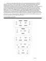
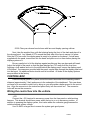
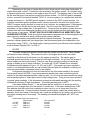
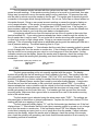
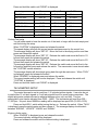
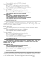
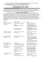
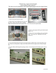
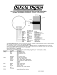
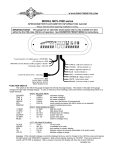
SERIES 3
VACUUM FLUORESCENT DIGITAL DASHBOARD
The latest in digital dashboard technology for the
street rodder, car, and truck enthusiast.
INSTALLATION AND OPERATION MANUAL
Please read this before beginning installation or wiring.
MODELS VFD3 & RET
4510 W. 61ST St. N., Sioux Falls, SD 57107
Phone: (605) 332-6513 FAX: (605) 339-4106
www.dakotadigital.com
[email protected]
©Copyright 2005 Dakota Digital Inc.
1
650066
Thank you for purchasing the Vacuum Fluorescent Digital Dashboard from DAKOTA
DIGITAL, the leader in custom automotive electronics. Representing the latest electronics
dashboard technology for the street rodder, car, and truck enthusiast alike, the digital
instrumentation uses state of the art vacuum fluorescent display technology to give the driver up
to date and accurate information on the operation of his or her vehicle. As used in several
production automobiles, vacuum fluorescent displays give superior performance and visual
appeal over LCD or LED display systems. Emitting a blue/green light that can be filtered to a
wide variety of colors, the VFD system boasts excellent daytime visibility and while under
computer control, automatically dims for nighttime driving. Using microprocessor technology,
the digital dashboard gives the driver additional features and benefits not typically found on any
other brand or type of instrumentation. Digital accuracy and solid state reliability will give you,
the driver, quality service for miles down the road.
TYPICAL DISPLAY SETUPS
2
650066
WARNING
The vacuum fluorescent displays are made of glass and should be handled with care. Use
extreme care around the glass evacuation tubes (small tubes at the bottom of each
display) as bumping them may cause breakage and render the display useless.
MOUNTING DISPLAY SYSTEMS WITH SUBPANELS
When mounting instrumentation systems mounted to a Lexan subpanel, begin by
removing the subpanel from the aluminum. Cut an opening in the dash just smaller than the
outer dimensions of the aluminum panel. Remove all nuts and washers from the studs on the
back side of the panel and insert into the hole. Next, install four washers or clips and secure
with a nut on each. This is what holds the panel to the dashboard. Now, install a nut on each
stud and set the display panel in place over the studs. If the studs were bent slightly inward
from securing the aluminum panel, you may have to bend them outward to line up with the holes
on the lexan subpanel. Always lay the display panel aside when not in use to avoid accidentally
damaging the displays. Once aligned, secure it with an additional four nuts. Leave a gap of no
less than 1/8" between the display glass and the front lens material. Be careful not to compress
the glass against the front lens. Again, note that the displays are glass and should be handled
with care. Use extreme care around the glass evacuation tubes (small tubes at the bottom of
each display) as bumping them may cause breakage and render the display useless.
MOUNTING SYSTEMS WITH DISPLAYS MOUNTED TO ALUMINUM
When mounting year specific aluminum panel, cut an opening into the dashboard if
necessary and secure the entire panel with the instrumentation using the appropriate mounting
hardware. Some panels are set into the front of the dash while others are installed from the rear
of the dash. The exact mounting configuration will depend on what year car and panel you are
installing.
MOUNTING SINGLE LENS SYSTEMS
Your DAKOTA DIGITAL single lens system will come to you with a single plexiglass lens
and instrumentation that is mounted in an aluminum case. The lens and the instrumentation
have corresponding mounting holes. After you have affixed the mounting studs of your choice
to the backside of your dash, the lens piece should be slid over the studs followed by the display
system. The lens can be secured with either washers and nuts, or by a bead of RTV around the
back side of the lens and case. If RTV is used, the system will need to be held in place until it
has had time to cure. The lens should be tight against the aluminum display case.
MOUNTING KITS INTO ORIGINAL DASHES
When installing the display system into the original bezel, several steps must be taken to
prepare the bezel. The first is to remove the cluster from the dashboard and all instrumentation
from the bezel. You should essentially be left with a bare chrome or metal bezel. Remove all
felt inserts from the back side of the bezel that sit between the lens and the chrome.
3
650066
55-56 Chevy car chrome bezel shown with lens and display opening outlines.
Next, take the supplied lens, with the lettering facing the front of the dash and place it in
the chrome bezel. Lay a bead of RTV around the back side of the lens to secure it in place.
After the RTV has cured, the display panel is ready to be placed on the bezel. If studs were
supplied with the panel, screw them into the bezel and place a nut on them before placing the
display system on it.
Be very careful not to hit the displays against anything as they are glass and will break.
Adjust the height of the panel so that the glass displays are 1/8" away from the front lens.
Applying a lock washer and nut to the studs behind the display panel, secure the display panel
to the bezel. If screws were provided with the panel, secure them through the display panel and
into the bezel. No additional holes should need to be drilled. All holes in the display systems
are pre-drilled at the factory.
CONTROL BOX
Once the display panel is in place, mount the control box within the connecting cable's
distance (approximately 3 feet) and secure to the underside of the dashboard. This case does
not have to be mounted to metal, but by doing so you will provide a better ground to the control
box. Align the connector in the socket and press firmly into the control box. The connector
locks will secure the connector.
Wiring the control box into the vehicle.
+12V
Connect the +12V terminal to accessory power from the fuse panel or vehicle wiring
harness. This terminal should have power when the key is on or in accessory position. In
addition to powering the display system, this is also where the voltmeter gauge senses the
vehicle electrical system voltage.
Use 18 AWG or larger wire to ensure the system gets good power.
4
650066
Never connect this to a battery charger alone. It needs to have a 12 volt battery
connected to it. Battery chargers have an unregulated voltage output that will cause the system
to not operate properly.
GROUND
This is the main ground for the display system. A wire should be run from this terminal to
the vehicle’s main ground location at the chassis or engine block. Do not use the dash or a
dash support brace for the ground connection.
Use 18 AWG or larger wire to ensure sufficient grounding. Proper vehicle grounding is
extremely important for the gauges to read and operate correctly. The engine block should
have heavy ground cables to the battery, frame, firewall, and body. Failure to properly ground
the engine block or the control box can cause incorrect or erratic operation.
DIMMING
The gauges are designed to dim down when the headlights are turned on. This is to
reduce the display intensity at night so the gauges do not cause eye strain or reduced night
vision. Connect this to the tail light or parking light circuit so that it has 12 volts whenever the
headlights are on. When this terminal does not have power the display system will be at full
brightness. When power is applied, the display dims to an adjustable level. The night
brightness level is adjustable two different ways.
The default method is to have the system to dim to a preset level when the lights are
turned on. This preset brightness is adjusted in the setup menu “DIM”. See DIM ADJ for a
description of the second method.
DIM ADJ
The second method allows you to have a dash mounted control to vary the brightness
while the headlights are on. This requires a 10k potentiometer or Dakota Digital’s DIM-1 kit. A
stock headlight rheostat will not work. The dash mount dimmer has two wires, one connects to
the DIM ADJ terminal and the other connects to ground. The dash mount dimmer will only vary
the display brightness when the DIMMING terminal has power.
SPEED
The vehicle speed sensor (VSS) connects to this to tell the system how fast the vehicle is
moving. For two wire speed sensors, like the one Dakota Digital supplies with this system, the
polarity of the wires does not matter. Connect one wire to ground and the other to the speed
terminal. The speed sensor ground wire should be brought back to the control box to ensure a
proper signal is received. Twisting the ground and signal wires around each other provides an
additional level of interference protection. The speed signal wire should not be routed along
side ignition or other high current or high voltage wires.
For vehicles which already have a vehicle speed signal, tap into the VSS wire and
connect it to the speed terminal. You may have to consult a vehicle service manual or wiring
diagram to determine wire color and location.
This system can accept 4000 ppm – 128000 ppm speed signals. The sensor that Dakota
Digital provides is an 8000 ppm type. The speedometer is fully adjustable and calibration is
discussed in a later section. Failure to calibrate the speedometer may cause your
odometer mileage to increase very rapidly if the speedometer is reading too fast.
5
650066
TACH
Depending on the type of system that you have there may be a bar graph tachometer, a
digital tachometer, or both. Connect the tach terminal to the ignition system. On vehicles using
a separate ignition coil, connect to the negative side of the coil. The negative side of the coil will
be the wire that goes to the points or electronic ignition module. For GM HEI ignition equipped
motors, connect to the terminal marked “TACH” or on some systems, to a single white wire with
a spade terminal on it. On MSD ignition systems, connect to the TACH output terminal. On
computer controlled ignition systems consult a service manual for the wire color and location.
GM LS1 engines require the tach to be set up for a 4 cylinder, low voltage signal. With magneto
system connect to the kill wire for the tach signal. Do not connect the TACH terminal to the
secondary, or high voltage side, of the ignition coil. To ensure that the ignition system does not
interfere with any other dashboard functions, do not run the tachometer wire along side any
other sender or input wires. DO NOT USE SOLID CORE SPARK PLUG WIRES WITH THIS
DASHBOARD SYSTEM. Solid core ignition wires cause a large amount of electromagnetic and
radio frequency interference which can disrupt the system operation.
The tachometer is compatible with almost all gasoline engines. The engine cylinder
selection, display update rate, tach signal type, and rpm warning point can be adjusted in the
setup menu under “TACH”. If a diesel engine is being used then you will need a tach interface,
such as Dakota Digital’s DSL-1 or DSL-2.
WATER
The water temperature sender included with this system must be used. Other senders
will cause incorrect readings. The sender mounts on the engine block or into the intake
manifold so that the end of the sensor is in the engine coolant flow. The sender gets its
electrical ground connection to the engine block through its threads. Do not use Teflon tape or
thread sealant on the sender threads. Doing so can cause incorrect readings or cause the
gauge to display an out of range indication. A sender with 1/8 NPT thread size is normally
included along with adapters to go to 1/4, 3/8, and ½ NPT. If the engine you have requires a
metric or non-standard thread size you can contact Dakota Digital for availability or check your
local auto parts dealer or hardware store for an adapter.
A single wire should be run from the terminal on top of the water sender to the control
box terminal marked WATER. If your wiring harness already has a wire routed through the
vehicle for the water temperature then it may be used. Do not route the water sender wire along
side a spark plug wire or other high current or high voltage wires. Doing so can cause incorrect
or erratic gauge readings. If the temperature exceeds an adjustable warning point the reading
will flash as a warning of high temperature. The default warning point is 250°F.
If the water display shows “---“ this indicates that the control box is sensing a short to
ground or out-of-range error from the sender or sender wire. If the water display shows “EEE”
this indicates that the control box is sensing an open circuit or out-of-range error from the
sender or sender wire. If either indication remains on the display, inspect the sender wire for
damage, check the routing of the sender wire, check the sending unit grounding, and check that
the correct sending unit is connected. The sending unit should be stamped with “VDO” and
“150°C”.
Replacement sender part numbers are:
Dakota Digital
1/8” NPT
SEN-04-1
3/8” NPT
SEN-04-2
½” NPT
SEN-04-4
12mm
SEN-04-6
VDO equivalent
323 057
323 059
323 060
323 092
6
650066
OIL
The oil pressure sender included with this system must be used. Other senders will
cause incorrect readings. If the sender mounting location is too small or is restricted, then pipe
fittings may be required to move the sender away from the restrictions. Oil pressure line may
also be used to remote mount the sender to the fire wall. The sender gets its electrical ground
connection to the engine block through its threads. Do not use Teflon tape or thread sealant on
the sender threads. Doing so can cause incorrect readings or cause the gauge to display an
out-of-range indication. If the sender is being remote mounted away from the engine, make
sure the sender case is ground well. The sender has 1/8 NPT thread size. If the engine you
have requires a different thread size you will need to use an adapter to convert the thread size.
Adapters can be found at your local auto parts dealer or hardware store.
A single wire should be run from the terminal on top of the oil sender to the control box
terminal marked OIL. If your wiring harness already has a wire routed through the vehicle for
the oil sender then it may be used. Do not route the oil sender wire along side a spark plug wire
or other high current or high voltage wires. Doing so can cause incorrect or erratic gauge
readings. If the oil pressure drops below an adjustable warning point the reading will flash as a
low oil pressure warning. The default warning point is 10 psi.
If the oil display shows “—“ this indicates that the control box is sensing a short to ground
or out-of-range error from the sender or sender wire. If the oil display shows “EE” this indicates
that the control box is sensing an open circuit or out-of-range error from the sender. If either
indication remains on the display, inspect the sender wire for damage, check the routing of the
sender wire, check the sending unit grounding, and check that the correct sending unit is
connected.
Replacement sender part numbers are:
Dakota Digital
VDO equivalent
SEN-10-2
360 003
FUEL
The fuel gauge sending unit is not normally supplied with the system. The display
system will usually use the fuel sending unit that is already in the tank. The sending units that
are compatible with this system are as follows: GM, Ford, VDO, and Stewart Warner. It is also
possible to program in a custom setting for senders that are not pre-programmed into the
system. The Stewart Warner sender type is used by most after-market gauges. A single wire
should be run from the fuel sender to the control box terminal marked FUEL. If your wiring
harness already has a wire routed through the vehicle for the fuel sender then it may be used. If
using a wire from an existing harness, make sure that the wire does not have power. The fuel
sender gets power from the control box only. Fuel senders get their ground from the sender
mounting plate. Make sure that a ground wire is connected from one of the sender mounting
bolts to the vehicle frame.
The fuel sender type is selected using the setup menu under “FUEL”. The settings are
discussed later in the section on internal adjustments. Anytime the fuel level is below 10% the
reading will flash as a warning of low fuel.
The fuel gauge will initially display “FL” until the fuel sender type has been set. If the fuel
display shows “—“ this indicates that the control box is sensing a short to ground or out-of-range
error from the sender or sender wire. If the fuel display shows “EE” this indicates that the
control box is sensing an open circuit or out-of-range error from the sender. If either indication
remains on the display, inspect the sender wire for damage, check the routing of the sender
wire, check the sending unit grounding, and check that the sender selection is set correctly for
the sending unit that is connected.
7
650066
CHECK
The check engine terminal is used with fuel injection ECM’s to display engine problems
and trouble codes. The CHECK input is activated by a ground signal from the ECM. Whenever
the check input is grounded the system will display “ENGINE” on the message display. This
message can be cleared by pressing and holding switch 2.
When the ECM is placed into diagnostic mode trouble codes can be read by counting the
flashes. Consult a service manual for the fuel injection system that you have for further
information on trouble codes.
With some ECM’s a 12 volt light bulb may need to be connected in addition to our
CHECK input in order to provide proper current loading. In this case both the bulb and our
display system indicator would both come on when the check engine wire was set.
BRAKE
The BRAKE terminal can be used as a brake system warning indicator. The BRAKE
input is activated by a ground signal from the brake pressure switch on the master cylinder or
from the parking brake set switch. Connect a wire from this terminal to the pressure switch on
the master cylinder or consult a vehicle service manual to determine color and location of an
existing wire. Whenever the BRAKE input is grounded the system will display “BRAKE” on the
message display. This message can be cleared by pressing and holding switch 2.
CRUISE
The CRUISE terminal can be used as a cruise engaged indicator. The CRUISE input is
activated by a ground signal from a compatible cruise control harness. Whenever the CRUISE
input is grounded the system will display a small “c” to the right of the speedometer
WAIT
The WAIT terminal can be used as a wait to start or glow plug indicator. The WAIT input
is activated by a 12 volt signal from the glow plugs. Whenever the WAIT input is powered the
system will display “WAIT” on the message display. This message can be cleared by pressing
and holding switch 2.
4x4
The 4x4 terminal can be used on four wheel drive vehicles. The 4x4 input is activated by a
ground signal from a switch on the transfer case. Connect a wire from this terminal to the switch
on the transfer case. Whenever the 4x4 input is grounded the system will display “4 WD” on the
message display. When signal turns off, the system will display “2 WD” on the message
display.
HI BEAM
The HI BEAM terminal is activated by a 12 volt signal from the headlight high beam wire.
When the terminal has 12 volts, an indicator will light up to the lower right of the speedometer
display. An existing wire from the vehicle for the high beam indicator can be used or a new wire
can be connected from the high beam side of the hi beam/low beam switch.
LEFT
8
650066
The LEFT terminal is activated by a 12 volt signal from the turn signal switch. When this
terminal has 12 volts, an arrow will light up to the left of the speedometer display. An existing
wire from the vehicle for the left turn indicator can be used or a new wire can be connected from
the turn signal switch.
RIGHT
The RIGHT terminal is activated by a 12 volt signal from the turn signal switch. When
this terminal has 12 volts, an arrow will light up to the right of the speedometer display. An
existing wire from the vehicle for the right turn indicator can be used or a new wire can be
connected from the turn signal switch.
SHIFT
The SHIFT terminal is an output for a relay or small light. The output is ground-activated
when the preset rpm limit is exceeded. This output can turn on a 4 Watt or smaller 12 volt bulb
or can activate a relay to turn on a larger bulb. To wire a warning light to this output, connect
one wire from the bulb to 12 volt accessory power and connect the other wire to the SHIFT
terminal.
GEAR SHIFT INDICATOR INPUT
The GEAR terminal is used for the gear shift indicator. The indicator is built into every
system but it will not light up unless a Dakota Digital GSS-1000/2000/5000 gear shift sending
unit is connected to tell it what gear the transmission is in. The gear shift sending unit is not
included with the system and must be purchased separately. The GEAR terminal will connect to
the FIRST terminal on a GSS-1000 or to the 1-wire terminal on a GSS-2000 or GSS-5000.
Follow the instructions in the GSS manual for use with a single wire display system. When the
gear shift sending unit is connected, the gear name will be shown on the message display.
SW 1 or Speed switch
The SW 1 terminal is used for selecting the various speed, distance, and performance
displays and also for entering the setup menu. The SW 1 input is activated by a ground
connection. The push button switch supplied (or any normally open switch) is wired by
connecting one terminal to SW 1 and the other terminal to a ground. When the button is
pressed and released, the speed message display will change. When the button is pressed and
held for a few seconds, any re-settable information displayed will be zeroed. On systems with
two message displays the one below the speed is dedicated to speed/performance messages.
On systems with one message display the speed/performance and rpm/warn messages will use
the same display.
SW 2 or Tach switch
The SW 2 terminal is used for selecting the various rpm, engine, and warning displays
and also for entering the demonstration mode. The SW 2 input is activated by a ground
connection. The push button switch supplied (or any normally open switch) is wired by
connecting one terminal to SW 2 and the other terminal to a ground. When the button is
pressed and released, the tach message display will change. When the button is pressed and
held for a few seconds, any re-settable information displayed will be zeroed. On systems with
two message displays the one below the tach is dedicated to rpm/warn messages. On systems
with one message display the speed/performance and rpm/warn messages will use the same
display.
9
650066
To enter DEMO mode, press and hold the switch while turning the key on.
MESSAGE DISPLAYS
On systems with two message displays, switch 1 will toggle between the speed message
displays and switch 2 will toggle between the tach message displays.
On systems with one message displays, switch 1 will either switch from the tach
message to the speed message or toggle to the next speed message. Switch 2 will either
switch from the speed message to the tach message or toggle to the next tach message.
Speed message displays
ODOMTR
TRIP
SERVIC
0-60 T
HI SPD
QUARTR
QT MPH
KPH xxx
DESCRIPTION
.
odometer mileage (0-999,999)
trip odometer mileage (0-999.9)
miles since last service (0-9,999)
0-60 mph time in seconds (0-25.5)
high speed recall (0-255)
¼ mile time in seconds (0-25.5)
end of ¼ mile speed (0-255)
kph conversion (or mph conversion if metric)
Tach Message displays
HI RPM
RPM-WN
ENGINE
BRAKE
4 WD
WAIT
GEAR
HOURS
BAR (on systems with no bar graph)
RPM (on systems with no digital tach)
TACH (on systems with no digital tach)
DESCRIPTION
.
high rpm recall (0-18,000)
rpm warning point (displays “SHIFT” when exceeded)
check engine indicator
brake warning indicator
4 wheel drive indication
diesel wait to start indicator
gear shift position indicator
hours system has been on with tach signal (0-999.9)
bar tach readout on message display (0-8)
digital tach readout on message display
digital tach readout on speed display
WIRE COLOR CODE FOR GM WIRING HARNESS
On the connector that originally plugged into the instrument cluster:
Function
Color
------------------------------------------------------------------+12 volt
Pink/Black or Pink
Ground
Black
Oil sender
Tan or no wire if mechanical
Water sender
Dark green
Fuel sender
Pink or light brown (should not have power)
Left turn
Light blue
Right turn
Dark blue
High beam
Light green
Brake warn
Tan/white or tan
10
650066
11
650066
GAUGE SYSTEM FEATURES
Mileage readings
• Million mile odometer
• Re-settable trip mileage (0-999.9)
• Re-settable service mileage (0-9999)
Performance readings
• High speed recall. This is reset at power up and can be manually reset.
• High rpm recall. This is reset at power up and can be manually reset.
• 0-60 mph (0-100kmh) time. This is reset automatically when speed is zero.
• ¼ mile time. This is reset automatically when speed is zero.
• ¼ mile end speed. This is reset when the ¼ mile time restarts.
Hour meter
• Re-settable hours (0-999.9)
English/metric conversion
• Alternate speed can be displayed on message display.
Special tachometer displays
• On systems that do not have bar graph displays, a bar tach can be shown on the
message display.
• On systems that do not have a digital tachometer display, the rpm can be shown on the
message display or the tachometer reading can be switched onto the speed display.
Demonstration mode
• Holding switch 2 while turning on the key will start the system going through a preset
sequence of readings. To exit the demo mode, turn the key off. You may also wire up a
separate switch to power the gauges for demo mode without powering the entire vehicle.
Built-in Indicators
• Left/Right Turn signal indicators
• High Beam indicator
• Check Engine indicator
• Brake warning indicator
• 4x4 indicator
• Wait to Start indicator
• Cruise control indicator
• Gear position indicator which displays full gear word
Special outputs
• Shift output to turn on external light
• Selectable 2000 ppm or 4000ppm speed output for cruise or ECM
12
650066
Setting up the control box
SETUP MENU
Main Menu
SPEED
Sub Menu
AUTO
ADJUST
UNIT
MPH F
KPH C
OUTPUT
2K PPM
4K PPM
DESCRIPTION
auto calibrate speed
adjust calibrate speed
select mph F or kph C units
.
TACH
ENGINE
UPDATE
WARN
SIGNAL
NORMAL
LO VLT
set engine cylinder setting
set rpm update rate
set rpm shift warning point
select normal or low voltage tach signal
FUEL
SENDER
CUSTOM
GM 30
GM 90
GM 250
F 10
F 150
V 180
SW 33
CUSTOM
TEST
set fuel sender type
calibrate custom fuel sender
display sender ohm reading
WATER
UNIT
WARN
TEST
select mph F or kph C units
set high temp warning point
display sender ohm reading
OIL
WARN
TEST
set low psi warning point
display sender ohm reading
speed output rate
DIM
change preset night dimming
DONE
restart system with new settings.
13
650066
SPEEDOMETER SETUP
Press and hold SW 1 switch, then turn the key on and start the engine. Once the engine
is running, release the switch. When “SPEED” is displayed, press the switch again and then
release it. The message display should switch between “AUTO”, “ADJUST”, “UNIT”, and
“OUTPUT”.
METRIC SELECTION
If you are setting the system up for metric displays, press the switch when “UNIT” is
displayed.
Press and release the switch until “KPH C” is displayed.
Press and hold the switch unit “DONE” is displayed.
SPEED CALIBRATION
There are two methods for calibrating the speedometer, auto cal and adjust. Either one
can be used. Auto cal requires that you have one measured mile marked out (km for metric).
Adjust requires you to follow another vehicle going at a set speed or timing your self over a mile
to determine your speed.
Auto Cal
When “AUTO” is displayed press and release the switch. The speedometer will display
“SEt”, the fuel, volt, oil, and water will display normally, and the message display will show
zeroes. You should now begin driving the measured mile. The message display will count the
number of pulses received from the sensor. The message display cannot be used to determine
when a mile has been driven. Once you reach the end of your marked mile, press the switch
again. The calibration is now done.
Adjust
When “ADJUST” is displayed press and release the switch. The system will restart with
“ADJUST” on the message display. The fuel, volt, oil, water, and tach will operate normally.
The speedometer will show the speed reading. Begin driving at a known speed. Press switch 1
to increase the speedometer reading and press switch 2 to decrease the speedometer reading.
When the speedometer is correct you can stop and restart the system. The new calibration will
be saved.
Speed Output
If a speed output signal is need for an ECM or cruise control, the 2k ppm terminal can be
used. This will normally provide a 2000 pulse per mile signal after the speedometer has been
calibrated. If you need a 4000 pulse signal, go to the SPEED setup menu and then select
“OUTPUT”.
Press and release the switch until 4K PPM is displayed.
Press and hold the switch until “DONE” is displayed.
FUEL SETUP
The control box can read 7 different types of preset fuel senders and can also be
programmed for a custom fuel sender setup. Press and hold SW 1 switch while turning the key
on. Release the switch. When “FUEL” is displayed, press the switch again and then release it.
The message display should switch between “SENDER”, “CUSTOM”, and “TEST”.
Sender Selection
When “SENDER” is displayed press and release the switch.
Press and release the switch until the desired setting is shown. The preset types are
listed in the table below.
14
650066
Press and hold the switch until “DONE” is displayed.
Sender type
Menu
Empty R
Full R
GM 0-30 ohm
GM 0-90 ohm
GM 30
GM 90
0 ohms
0 ohms
30 ohms
90 ohms
GM 40-250 ohm
FORD 73-10 ohm
GM 250
F 73
40 ohms
73 ohms
249 ohms
10 ohms
FORD 20-150 ohm
F 150
20 ohms
150 ohms
VDO 10-180 ohm
SW/SUN 33-240
User programmed
V 180
SW 33
CUSTOM
10 ohms
240 ohms
User settable
180 ohms
33 ohms
User settable
Custom Fuel setup
You will either need to have the sender out of the tank, or begin with the tank empty and
add fuel during the setup.
When “CUSTOM” is displayed press and release the switch.
The speed display will show the current sender resistance seen by the control box.
The message display will show “SET 00”. Move the float to the empty position and then
press and release the switch.
The message display will show “SET 33”. Release the switch and move the float to 1/3
full and then press and release the switch.
The message display will show “SET 66”. Release the switch and move the float to 2/3
full and then press and release the switch.
The message display will show “SET 99”. Release the switch and move the float to the
full position and then press and release the switch. The new sender is now stored under
the “CUSTOM” sender selection.
The message display will show begin going back through the main menu. When “FUEL”
is displayed, press and release the switch.
When “SENDER” is displayed press and release the switch.
The current sender setting will now be displayed. Press and release the switch until
“CUSTOM” is displayed.
Press and hold the switch until “DONE” is displayed.
TACHOMETER SETUP
The control box can be set to read from 1-15 cylinder ignition signals. It can also be set
to read either 12 volt tach signals or 5 volt tach signals found on some engine computers. The
digital tachometer update rate can be adjusted between slow, mid, and fast. The rpm
warning/shift point can be adjusted from 2200 – 14800. The tachometer will read from 350 –
17,500 rpm. At rpm’s above 9990 the reading will be displayed as rpmx1000 (12,000=12.00).
Press and hold SW 1 switch while turning the key on. Release the switch. When “TACH”
is displayed, press the switch again and then release it. The message display should switch
between “ENGINE”, “UPDATE”, “WARN” and “SIGNAL”.
Engine cylinder setup
When “ENGINE” is displayed press and release the switch.
The current cylinder setting will be displayed.
Press and release the switch until the desired setting is displayed.
15
650066
Press and hold the switch until “DONE” is displayed.
Display update setup
When “UPDATE” is displayed press and release the switch.
The update setting will be displayed. (1=slow, 2=mid, 3=fast)
Press and release the switch until the desired setting is displayed.
Press and hold the switch until “DONE” is displayed.
Rpm warning setup
When “WARN” is displayed press and release the switch.
The current warning point will be displayed.
Press and release the switch until the desired setting is displayed.
Press and hold the switch until “DONE” is displayed.
Tach signal setup
When “SIGNAL” is displayed press and release the switch.
The setting will be displayed. (NORMAL or LO VOLT)
Press and release the switch until the desired setting is displayed.
Press and hold the switch until “DONE” is displayed.
WATER TEMP SETUP
Press and hold SW 1 switch while turning the key on. Release the switch. When
“WATER” is displayed, press the switch again and then release it. The message display should
switch between “UNIT”, “WARN” and “TEST”.
METRIC SELECTION
If you are setting the system up for metric displays, press the switch when “UNIT” is
displayed.
Press and release the switch until “KPH C” is displayed.
Press and hold the switch unit “DONE” is displayed.
Temp warning setup
When “WARN” is displayed press and release the switch.
The current warning point will be displayed.
Press and release the switch until the desired setting is displayed.
Press and hold the switch until “DONE” is displayed.
OIL PRESSURE SETUP
Press and hold SW 1 switch while turning the key on. Release the switch. When “OIL” is
displayed, press the switch again and then release it. The message display should switch
between “WARN” and “TEST”.
Pressure warning setup
When “WARN” is displayed press and release the switch.
The current warning point will be displayed.
Press and release the switch until the desired setting is displayed.
Press and hold the switch until “DONE” is displayed.
DIM PRESET SETUP
Press and hold SW 1 switch while turning the key on. Release the switch. When “DIM”
is displayed, press the switch again and then release it. 88 or 888 will be displayed on the fuel,
oil, volt, and water displays. The system will dim down to the current preset level.
16
650066
Press and hold SW 1 until the desired night brightness is shown. When the system
reaches its lowest brightness it will start over again at full brightness.
Once the night brightness is correct, press SW 2 to save it.
TROUBLESHOOTING GUIDE
This is a list of some problems and their solutions which may be encountered when installing your
instrumentation system. If you cannot determine what the problem is or how to solve it, please call our
technical assistance line (605) 332-6513 or email to [email protected].
* A note on vehicle grounding. *
The most common cause of problems with electric gauges is poor ground connections. The
engine block has the highest ground currents of any point in the vehicle. The ignition system, electric
gauge senders, starter, alternator, etc. all use the engine block for a ground point. Since the alternator is
grounded directly to the engine block all ground currents in the entire vehicle must pass through the
engine block while the engine is running. A weak or loose connection can cause all kinds of random
problems that may difficult to track down. The engine block should have heavy ground straps to both the
chassis and the body. The main negative cable from the battery should be connected directly to the
engine block.
Symptom
Possible Problem
Solution
----------------------------------------------------------------------------------------------------------------------------------System does not light up
Control box may not be getting
Check if the control box has
and LED off.
power.
12 volts connected to it.
Control box may not be getting
Check if the control box has
a ground.
a proper ground connection.
Do not use a battery charger to
power the system.
The control box may have
Contact Dakota Digital’s service
an internal problem
department with a description of
the problem.
System does not light up
and LED is on steady.
Control box may be getting too
low of a voltage.
Check if power to control box is
at least 11 volts.
Do not use a battery charger to
power the system.
System does not light up
and LED is flashing.
The display system may not be
getting power.
Insert the connector on the
display system wiring harness
into the slot on the side of the
control box. Be sure the pins
line up properly.
Check the display system wiring
harness for broken or cut wires.
One display does not
light up at all, all others
work correctly.
The display panel
corner of the display is white or
the display is cracked or broken
Return the display panel to
Dakota Digital for repair. Include
a phone number and address.
The tachometer will not
show a reading.
The control box is not connected
to the engine properly
The engine cylinder setting is
incorrect.
The tach signal setting is
incorrect.
Make sure the control box is
connected to your particular
ignition system properly.
Refer to the tach setup section
of the installation manual.
Refer to the tach setup section
of the installation manual.
The tachometer signal wire is
loose or broken.
The engine cylinder setting is
17
Check the connections at both
ends of the wire.
Refer to the tach setup section
650066
The tachometer reading
is incorrect.
Symptom
Possible Problem
Solution
----------------------------------------------------------------------------------------------------------------------------------incorrect.
of the installation manual.
The speedometer will
not show a reading.
The speed sending unit is not
connected to the control box
properly.
The speed sending unit being
used is not compatible with the
control box.
The speed sending unit is not
connected to the transmission
properly.
The sending unit wire is picking
up noise from nearby wires.
Check that both speed sending
unit wires are connected to the
control box properly.
Use the speed sending unit
supplied with the display
system.
Check that sender is mounted
properly.
Check that transmission has the
appropriate internal parts.
Isolate the sending unit wire from
motor and ignition wires.
The speedometer is reading
too fast or too slow.
The speedometer is not calibrated.
Refer to the Speed Calibration
section of the installation manual.
With the engine running and
the vehicle sitting still, the
speedometer reads higher
than zero.
A tachometer wire is too close to
to the speed sensor wire.
There is a ground problem between
the speed sensor and the control
box.
Reroute or isolate the tachometer
wire away from the speed wire.
Make certain the ground wire for
the speed sensor is connected
directly to the control box ground.
A display shows “EE”
Sending unit for that gauge
is not connected to the control
box.
Check the wire from sending unit
to the control box for breaks.
Make sure that the sending unit is
wired to the correct terminal.
Make sure the sending unit is
grounded properly.
Make sure the water and oil senders
have clean threads.
Use the water and oil senders that
were supplied with the system.
Refer to “Fuel Setup” section of the
installation manual to ensure that
the settings match your fuel sender.
Sending unit is not getting
grounded.
On the water or oil, the sending
unit is not the correct type.
On the fuel, the control box may be
set for the wrong fuel sender.
A display shows “- -“
The sending unit wire for that
gauge is shorted to ground.
Repair or replace shorted wire.
Fuel displays “FL”
The control box is set to an invalid
fuel sender setting.
Refer to “Fuel Setup”
section of the installation manual
to ensure that the settings match
your fuel sender.
The fuel display reads
backwards, incorrectly,
or does not change.
The control box may be set for
the wrong type of fuel sender.
Refer to “Fuel Setup”
section of the installation manual
to ensure that the settings match
your fuel sender.
Check the connections at both
ends of the fuel sender wire.
Make sure the fuel sender is
grounded properly.
Check the fuel sending unit with
an electrical multi-meter.
Use the custom fuel sender setup.
See the Fuel Setup section of the
manual for instructions.
650066
The fuel sender may not be
connected to the control box
properly.
The fuel sender may not be
operating properly.
The fuel sender may have a
non-standard resistance
range.
18
Symptom
Possible Problem
Solution
----------------------------------------------------------------------------------------------------------------------------------The oil or water display
The engine block may not be
Use heavy ground cables from the
reading is incorrect.
grounded to the chassis frame
battery to the engine block.
or body properly.
Make sure both ends of the cable
have clean metal-to-metal
connections.
Use a braided ground strap to
ground the engine block to the
chassis.
Use a large braided ground strap
to ground the engine block to
the body or fire wall.
The threads are not grounding to
Make sure no thread sealant is used
the engine block.
on any of the threads.
The sending unit wire is picking
Isolate the sending unit wire from
up noise from nearby wires.
motor and ignition wires.
The sending unit is not
compatible with the control box
The sending unit has failed.
Use the sending unit provided
the display system.
Return the sending unit to
Dakota Digital for replacement.
The gear shift indicator
does not light up.
The optional gear shift sending
unit is not connected to the
Connect the sending unit to the
control box using the
sending unit.
The gear shift indicator
does not operate
properly.
The gear shift decoder
is not connected properly.
The internal turn signal
and high beam
indicators do not light up.
The control box is not connected
to the vehicle's electrical
system properly.
Check the wires connected to the
HIGH, LEFT, and RIGHT
terminals on the control box.
The check engine
indicator does not
operate properly.
The control box is not connected
to a TPI control module.
This feature is designed to work
with engine control systems that
provide an active low signal.
The check engine
indicator stays on
all of the time.
The Engine Control Module
(ECM) needs to see the
load of a light connected to it.
Connect a light or similar load
to the ECM along with the
control box.
The Function switches
do not operate
properly.
The push-button switches are
not connected to the control
box.
The wrong type of switch is
being used.
Momentary push-button or toggle
switches must be connected to
the SW1 and SW2 terminals
as described in the manual.
The switch terminal connected
to the control box should
normally be open. When the
the switch is activated, the
terminal should make contact
to ground.
Sw 2 terminal is constantly
connected to ground.
Disconnect or replace the
SW2 switch.
The display system starts
up in the demonstration
mode and remains in it.
19
Check the connections to the
transmission linkage and to
the control box.
Check gear shift decoder
Installation manual.
650066
CLOCK
Wiring instructions for VFD systems with a clock built in.
Introduction:
The clock displays the current time in 12 hour format with an AM/PM indicator. The AM/PM indicator
appears as a dot that will be displayed in the upper left corner. The dot will be on every other 12 hour period (on
during AM and off during PM). The high brightness display matches our other Odyssey and STR series gauges
and has the same night brightness dimming capability. Features included are:
• Quartz accuracy.
• Night dimming feature.
• Very low standby power to prevent battery drain.
• High Visibility VFD display for sunlight readability.
Operation:
The gauge needs the red, orange, and black wires connected to operate. The red wire should have
switched 12 volt power from an ACC. point on the fuse panel. The orange wire should have constant 12 volt
power. The black wire should be connected to a good ground point. When the blue wire has 12 volts, it will dim the
display for night viewing.
Setting the time:
Using a small, thin object such as a pen or hairpin, press “set” buttons through front lens access holes.
The access holes are on the right side of the lens. Top “set” button advances hours, bottom “set” button advances
minutes.
Wiring:
BLACK
RED
-
ORANGE
-
BLUE
-
connect to a good ground point in the vehicle.
connect to switched 12 volt power point.
(An accessory terminal will work for this.)
connect to a constant 12 volt power point.
(This will keep the correct time.)
connect to the tail light circuit.
SERVICE AND REPAIR
DAKOTA DIGITAL offers complete service and repair of its product line. In addition, technical consultation is available to help you work through any
questions or problems you may be having installing one of our products. Please read through the Troubleshooting Guide. There, you will find the solution to most
problems.
Should you ever need to send the unit back for repairs, please call our technical support line, (605) 332-6513, to request a Return Merchandise
Authorization number. Package the product in a good quality box along with plenty of packing material. Ship the product by UPS or insured Parcel Post. Be sure
to include the RMA number on the package, and include a complete description of the problem with RMA number, your full name and address (street address
preferred), and a telephone number where you can be reached during the day. Any returns for warranty work must include a copy of the dated sales receipt from
your place of purchase. Send no money. We will bill you after repair.
Dakota Digital Limited Lifetime Warranty
DAKOTA DIGITAL warrants to the ORIGINAL PURCHASER of this product that should it, under normal use and condition, be proven defective in
material or workmanship for the lifetime of the original vehicle it was installed in, such defect(s) will be repaired or replaced at Dakota Digital’s option.
This warranty does not cover nor extend to damage to the vehicle’s systems, and does not cover removal or reinstallation of the product. This Warranty
does not apply to any product or part thereof which in the opinion of the Company has been damaged through alteration, improper installation, mishandling, misuse,
neglect, or accident.
This Warranty is in lieu of all other expressed warranties or liabilities. Any implied warranties, including any implied warranty of merchantability, shall be
limited to the duration of this written warranty. No person or representative is authorized to assume, for Dakota Digital, any liability other than expressed herein in
connection with the sale of this product.
4510 W. 61ST St. N., Sioux Falls, SD 57107
Phone: (605) 332-6513 FAX: (605) 339-4106
www.dakotadigital.com
[email protected]
©Copyright 2005 Dakota Digital Inc.
20
650066