1
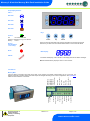
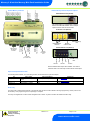
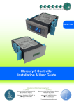
Mercury PR0710-MPA PR0722 Intuitive PR0750-MPA PR0722 Mercury 2 & Intuitive Mercury Mini Pack / Condenser Controller Installation & User Guide For Products: - PR0710, PR0711, PR0720, PR0721 Resource Data Management Ltd 80 Johnstone Avenue, Hillington Industrial Estate, Glasgow, Scotland G52 4NZ UK +44(0)141 810 2828 Switchboard [email protected] Technical Support [email protected] Sales Enquiries www.resourcedm.com Mercury 2 & Intuitive Mercury Mini-Pack Installation Guide Table of Contents: THE MERCURY & INTUITIVE RANGE .............................................................................................................. 3 Variants ............................................................................................................................................................ 3 Configuration ..................................................................................................................................................... 3 Compatible Network Interfaces ........................................................................................................................ 3 Front Display Features ...................................................................................................................................... 4 Connections ....................................................................................................................................................... 4 Mercury Mk2 ....................................................................................................................................................... 4 Intuitive Mercury Controller Intuitive Mercury Network Expansion Options ...................................... 5 Input and Output Allocation Table ................................................................................................................... 5 See Status Input ................................................................................................................................................. 5 Alarm relay ....................................................................................................................................................... 5 Pressure Transducer Connection, Mercury Mk2 ............................................................................................. 6 Setting up the controller ................................................................................................................................... 6 Setup through front buttons ............................................................................................................................. 7 Setup Function Menu (Common to all types)................................................................................................... 7 Recommended set-up method ......................................................................................................................... 7 rtc. Real time clock (This will automatically synchronise on network systems) ............................................... 7 type. Set/view controller type ........................................................................................................................... 7 Inp .................................................................................................................................................................... 7 PArA. Set/view parameters (This can be achieved at the network front end) ................................................. 8 Unit. Set/view temperature unit and Probe type .............................................................................................. 8 Parameter Tables ............................................................................................................................................... 8 Parameter Descriptions .................................................................................................................................. 10 Stage Inputs ..................................................................................................................................................... 11 Control - Staged Operation ............................................................................................................................. 11 Run-Proof ......................................................................................................................................................... 11 Floating Head Pressure................................................................................................................................... 11 Network Configuration .................................................................................................................................... 12 485 Legacy module ........................................................................................................................................ 12 Fast Network Address Reset ......................................................................................................................... 12 IP Futura module ............................................................................................................................................ 13 Viewing Input / Output Tables ........................................................................................................................ 14 Input/Output table ........................................................................................................................................... 14 Alarm Messages .............................................................................................................................................. 14 Network Alarms ............................................................................................................................................... 14 Probe Offset ..................................................................................................................................................... 15 Test Relay Outputs ........................................................................................................................................ 15 Remote Commands ......................................................................................................................................... 15 Specification .................................................................................................................................................... 16 Power requirements ....................................................................................................................................... 16 General........................................................................................................................................................... 16 Relay Specification ......................................................................................................................................... 16 Inputs.............................................................................................................................................................. 17 Installation ........................................................................................................................................................ 17 Dimensions ...................................................................................................................................................... 17 Mercury Mk2 .................................................................................................................................................. 17 Fixing .............................................................................................................................................................. 17 Intuitive Mercury controller ............................................................................................................................. 18 Cleaning ......................................................................................................................................................... 18 Disclaimer ......................................................................................................................................................... 18 REVISION HISTORY......................................................................................................................................... 19 Warning Ensure that all power is switched off before installing or maintaining this product Revision 1.5 Page 2 of 19 www.resourcedm.com Please Note Mercury 2 & Intuitive Mercury Mini-Pack Installation Guide The Mercury & Intuitive Range From Resource Data Management For Version 1.3 This Mercury Mini Pack controller is primarily intended for use in Pack or Condenser control applications. The controller is available in two hardware platforms, a flush mount model known as the Mercury Mk2 and a DIN rail mounted model known as the Intuitive Mercury, both of which are designed to be used in a control panel or electrical tray. The controller has 5 relay outputs that are configurable as Compressors/Loaders, when set as Type1 or Condenser Fans when set as Type 2. The controller has 5 status inputs which can be assigned as a Stage Input, General Alarm, Standby Mode or Temperature Probe. The 6th input allows for a pressure transducer interface (PR0722) to be used. The controllers operate a staged logic control algorithm which allows the user to configure the controller outputs to achieve the desired control. Both the Mercury and Intuitive Mercury controller have the same features with the Intuitive Mercury having additional benefits such as higher rated relays each protected by an integral fuse and fuse protection for the incoming power supply, all connections are plug in socket. There are multiple network interfaces to choose from including Ethernet. The controller supports only PT1000 probe types. Variants Description Mercury Mk2 Mini-Pack Intuitive Mercury Mini-Pack Mercury MK2 Transducer Interface Part Number PR0710-MPA PR0750-MPA PR0722 Configuration The controller provides two configuration options: Display value 1 2 Controller Type Pack Controller Condenser Controller Compatible Network Interfaces Mercury and Intuitive Mercury controllers are capable of connecting to either a TCP/IP local area network, an RS485 Genus compatible network, an RDM wireless mesh network or they can be used in standalone mode with no network output. To connect to a network you must add the correct communications module. Connecting to any of these communication modules will automatically be detected on power up and will affect the set up screens available to you. Description IP Futura (Single Mercury to IP Interface) RS485 Interface (Single Mercury to RS485 Interface) Mercury IP Switch (IP support for 10 controllers) Mercury IP Switch with Pressure/Humidity Inputs Wireless Mesh Interface (for single Mercury) Part Number PR0016 PR0026 PR0018 PR0018-PHI PR0730 The Intuitive Mercury Controller is supplied as standard with an internal RS232 network card, this allows connection to any of the above external network interfaces. Three alternative internal network cards are also available, these can be supplied factory fitted as an option or purchased separately as an interface kit. Description Intuitive Internal IP Network Card Interface Kit Intuitive Internal RS485 Network Card Interface Kit Intuitive Internal Wireless Mesh Network Card Interface Kit Part Number PR0770 PR0771 PR0772 Warning Ensure that all power is switched off before installing or maintaining this product Revision 1.5 Page 3 of 19 www.resourcedm.com Please Note Mercury 2 & Intuitive Mercury Mini-Pack Installation Guide Front Display Features LED’s: Not Used Not Used Not Used Not Used Keys On-Line Off No network attached Flashing Attempting to Log on to network Steady On-line Service (See Parameter 10 for setup) Enter Up Down Note: Function keys illuminate when pressed, illumination is turned off 20 seconds after the key is used. Press and hold the defrost button to force a manual defrost Alarm Main Display HACCP 4 character LED display, used to Suction or Discharge pressure and status messages. Note the Intuitive Mercury display is Green in colour when lit. Connections Mercury Mk2 Supply Neutral Relay 2 N/O Relay 2 Common Supply Live Relay 2 N/C Relay 5 N/O Not Used Relay 4 N/C Relay 1 N/C Relay 4 Common Relay 1 Common Relay 4 N/O Relay 1 N/O Relay 3 N/C Relay 3 N/O Relay 3 Common Stage Input Grounds Stage Input 1 Stage Input 2 Stage Input 3 Stage Input 4 Stage Input 5 Transducer Input Input and Output connections are made to the back of the controller, the RS232 communication port is on the side. The diagram shows the connection detail. Inputs and outputs are assigned according to the chosen configuration. See Input/Output tables for further details on connections. Warning Ensure that all power is switched off before installing or maintaining this product Revision 1.5 Page 4 of 19 www.resourcedm.com Please Note Intuitive Mercury Network Expansion Options Relay 4 Common Relay 4 N/O Relay 4 N/C Transducer Ground Input 5 Ground Input 4 Ground Input 3 Ground Input 2 Ground Input 1 Ground Intuitive Mercury Controller Relay 5 Common Relay 5 N/O Relay 5 N/C Mercury 2 & Intuitive Mercury Mini-Pack Installation Guide RS232 Network Card (Default) The Intuitive Mercury is supplied with an RS232 Network Card fitted as standard. Some example optional network cards are shown below IP Network Card (PR0770) Relay 1 N/C Relay 1 N/O Relay 1 Common Relay 2 N/C Relay 2 N/O Relay 2 Common Mains Supply 100-240vAC 50-60Hz Relay 3 N/C Relay 3 N/O Relay 3 Common N N/C L Rotary Address Switches Network Collision LED Network Activity LED RS485 Network Card (PR0771) Network Expansion Port Not Fitted (For future use) Network Activity LED A+ BGround Ground Screen PR0772 Wireless Mesh Option also available. The network interfaces work in the same way as there external counterparts. Input and Output Allocation Table The following tables indicate; on a controller type basis, the functions of the inputs and outputs. I/O Stage Inputs 1-5 Transducer Input Relays 1-5 Type 1 Pack Status Input or Temperature Probe Pressure Transducer Compressor or Loader Type 2 Condenser Status Input or Temperature Probe Comments See Status Input Pressure Transducer Fan See Interface Board Wire to N/O Contacts Alarm relay The alarm relay is assigned automatically to the first free relay that has not been utilised in the stage programming. At first power on this will be Relay 1 until programming of the output stage is complete. The relay is energised with no alarm and de-energised when in alarm. Any alarm condition will activate the alarm relay. Warning Ensure that all power is switched off before installing or maintaining this product Revision 1.5 Page 5 of 19 www.resourcedm.com Please Note Mercury 2 & Intuitive Mercury Mini-Pack Installation Guide Pressure Transducer Connection The controller uses an external 4-20ma interface board (PR0722) which allows a pressure transducer to be connected to the probe 6 input. Pressure transducers must be of the current loop 4-20mA type. Excitation voltage (12 Vdc) is provided for the transducer. The range of the transducer will vary according to the application, the Span and Offset parameters allow for this. Issue 2 Interface has a 4-20mA input and a 0 – 10V input for transducer. Note: The PR0722 works with PT1000 probes only (units selected as 0 or 1) Mercury Controller RS232 Socket Network Interface InterfaceBoard Board Interface PR0722 PR0722 Issue 1 Mercury Probe 6 Input (Green) Probe 6 Ground (Black) 4-20mA Input 12V Supply Pressure Transducer Note: Interface Board PR0722 Issue 1 is now obsolete and is superseded by Interface Board PR0722 Issue 2 Interface Board PR0722 Issue 2 The RJ45 socket labelled as “Mercury Controller” on the interface board connects to the Mercury Mini Pack controllers RS232 Comms port. A standard CAT5 patch lead should be used. Maximum cable length 0.1m. The Connector labelled “Probe INP” connects to Input 6 on the Mercury controller’s Probe 6 input. Maximum cable length 0.1m. Setting up the controller Access to the controller can be achieved several ways Through the front mounted buttons Direct access by PC or palm top into the controller’s RS232 comms port. This requires a software package available on the RDM website Through legacy front end panels on 485 networks Through the RDM Data Manager. Across an IP network. (Current controller IP address required) Warning Ensure that all power is switched off before installing or maintaining this product Revision 1.5 Page 6 of 19 www.resourcedm.com Please Note Mercury 2 & Intuitive Mercury Mini-Pack Installation Guide Setup through front buttons ENTER UP DOWN To enter setup mode, hold the Enter and Down buttons together for approximately 3 seconds until the message “Ent” appears on the display. Now press the Enter button again to enter the function menu. IO will be displayed. Scroll up or down to go through the list. Setup Function Menu (Common to all types) Display IO PArA Option View Inputs / Outputs and States Set/View Parameters Explained in Paragraph Input / output table Display Option nEt Set/view network configuration Explained in Paragraph Network Configuration Set view parameters SoFt View software version Set View Unit OFSt Probe Offset Probe Offset inP Probe type and Celsius/Fahrenheit option Sets 4-20mA or 0-10V Input test Test Outputs Test Outputs tyPE Set/View Controller Type Set/view controller type ESC Exit Setup mode rtc Set/view Clock (rtc = Real Time Clock) Real Time Clock Unit Recommended set-up method If you are not connecting to a network and want to set up the controller through the buttons we recommend you use the following order from the function menu. rtc. Real time clock (This will automatically synchronise on network systems) a. Use the up or down buttons to scroll through the display until the display reads “rtc” b. Press enter. The display will show “t-1”. press enter again c. Scroll hours up or down (0 – 23) press enter d. Use up button to select “t-2”, press enter e. Scroll minutes up or down (0 – 59) press enter f. Repeat for t-3 (seconds 0 – 59) g. Repeat for t -4 (Days up to 31) h. Repeat for t -5 (months up to 12) i. Repeat for t -6 (Year up to 99) j. Use up button to display “ESC”, press enter to display “rtc” Time clock is now set type. Set/view controller type a. From the function menu scroll to select type, press enter b. Use the up/down buttons to scroll through case/coldroom configuration types. (see configuration table on page 3) c. Press enter. d. Scroll to select “ESC” e. Press enter Controller type configuration is now set Inp The INP menu option is used to configure the controller to operate with either a 4–20mA or 0–10V input signal. Set to 0 for 4 – 20mA input Set to 1 for 0 – 10V Input Warning Ensure that all power is switched off before installing or maintaining this product Revision 1.5 Page 7 of 19 www.resourcedm.com Please Note Mercury 2 & Intuitive Mercury Mini-Pack Installation Guide PArA. Set/view parameters (This can be achieved at the network front end) a. From the function menu scroll to select PArA b. Pressing Enter while PArA is displayed will enter the parameter menu. The first parameter option will be displayed as P01. Pressing the Up or Down button will present the other parameter options P-02, P-03 etc. See the parameter list below to find what parameter number corresponds to which actual parameter. Pressing the Enter button will show the current value of the selected parameter. Press Up or Down to modify the value and press Enter again to save the value. The parameter list number will be displayed again. Two other options are present in the parameter menu – dFLt and ESC. Selecting ESC will exit setup mode. Selecting dFLt will reset all parameters back to the default values for the current type of controller. Unit. Set/view temperature unit and Probe type From the function menu scroll to select Unit Press enter and the value will be displayed: Probe Types 0 for PT1000 Celsius 1 for PT1000 Fahrenheit Use the up or down keys to select the units and press enter. This variant of controller can only use PT1000 probe types. Note If Probe type selected is degrees Celsius then Control Pressure will be in Bar. If Probe type selected is degrees Fahrenheit then Control Pressure will be in PSI. This function is now complete Parameter Tables Not all parameters apply to all controller types, for example P-19 is Condenser Offset which only applies to the Condenser Controller (Type 2), this parameter will not appear if the controller is set up as a type 1 (Pack Controller). In the following table, the type columns on the right hand side will be greyed out if that parameter does not apply to that controller type. Number Parameter Range Bar (Psi) P-02 P-03 Transducer Span* (Pack) Transducer Span* (Condenser) Transducer Offset* Target (Pack) -3.4 to 50.0 (-49.3 to 725) 3.4 to 50.0 (-49.3 to 725) -3.4 to 50.0 (-49.3 to 725) -3.4 to 50.0 (-49.3 to 725) 0.1 0.1 0.1 0.1 Bar/Psi Bar/Psi Bar/Psi Bar/Psi P-04 P-05 P-06 P-07 P-08 P-09 P-10 P-11 P-12 P-15 P-16 Target (Condenser) Target Above Target Below Stages Stage On Delay Stage Off Delay Fail Off / On Service Time Run Proof Optimisation Limit Control Type Probe Select 0.1 0.1 0.1 1 00:01 00:01 1 1 1 0.1 1 1 Bar/Psi Bar/Psi Bar/Psi P-17 P-18 P-19 P-44 P-45 P-46 P-47 P-48 P-49 P-50 Low Limit High Limit Condenser Offset Press 0oC / 32oF Press 10oC / 50oF Press 20oC / 68oF Press 30oC / 86oF Press 40oC / 104oF Press 50oC / 122oF Stage 1 Relay 1 -3.4 to 50.0 (-49.3 to 725) -3.4 to 50.0 (-49.3 to 725) -3.4 to 50.0 (-49.3 to 725) 0 - 5 00:00 - 60:00 00:00 - 60:00 0 = Off 1 = On 0 - 128 0 = Off 1 = On -3.4 to 50.0 (-49.3 to 725) 0 = Fixed, 1 = Floating 0 = Probe 1,1 = Probe 2 2 = Probe 3, 3 = Probe 4 4 = Probe 5 -3.4 to 50.0 (-49.3 to 725) -3.4 to 50.0 (-49.3 to 725) 0.0 - 10.0 -3.4 to 50.0 (-49.3 to 725) -3.4 to 50.0 (-49.3 to 725) -3.4 to 50.0 (-49.3 to 725) -3.4 to 50.0 (-49.3 to 725) -3.4 to 50.0 (-49.3 to 725) -3.4 to 50.0 (-49.3 to 725) 0 = Off. 1 = On 0.1 0.1 0.1 0.1 0.1 0.1 0.1 0.1 0.1 1 Bar/Psi Bar/Psi o C Bar/Psi Bar/Psi Bar/Psi Bar/Psi Bar/Psi Bar/Psi P-54 P-55 Stage 1 Relay 5 Stage 2 Relay 1 0 = Off. 1 = On 1 0 P-59 P-60 Stage 2 Relay 5 Stage 3 Relay 1 0 = Off. 1 = On 1 0 P-64 Stage 3 Relay 5 P-01 Step Units mm:ss mm:ss K Hrs Bar/Psi Default Bar (Psi) 13.8 (200) 34.4 (499) 0.0 (14) 2.1 (30) 12.7 (184) 0.5 (7) 0.5 (7) 0 00:10 00:10 0 60 0 2.0 (29) 0 0 8.2 (119) 23.0 (334) 6.0 6.0 (87) 8.2 (119) 10.9 (158) 14.2 (206) 18.1 (262) 23.0 (334) 0 Type 1 Pack Type 2 Condenser Warning Ensure that all power is switched off before installing or maintaining this product Revision 1.5 Page 8 of 19 www.resourcedm.com Please Note Mercury 2 & Intuitive Mercury Mini-Pack Installation Guide P-65 Stage 4 Relay 1 0 = Off. 1 = On 1 0 P-69 P-70 Stage 4 Relay 5 Stage 5 Relay 1 0 = Off. 1 = On 1 0 P-74 P-20 P-21 P-22 P-23 P-30 Stage 5 Relay 5 Alarm Delay HP Alarm LP Alarm LP Shutdown Status Fault 1 (Pack) 05:00 4.1 (59) 0.6 (9) 0.4 (6) 0 P-34 P-30 Status Fault 5 (Pack) Status Fault 1 (Condenser) P-34 P-40 P-41 dFLt Status Fault 5 (Condenser) Status Fault Delay General Fault Delay Restore default values 00:00 - 99:00 -3.4 to 50.0 (-49.3 to 725) -3.4 to 50.0 (-49.3 to 725) -3.4 to 50.0 (-49.3 to 725) 0 = Unused, 1 = Probe 2 = Comp N/O, 3 = Comp N/C 4 = Gen N/O, 5 = Gen N/C 6 = Std N/O, 7 = Std N/C 0 = Unused, 1 = Probe 2 = Cond N/O, 3 = Cond N/C 4 = Gen N/O, 5 = Gen N/C 6 = Std N/O, 7 = Std N/C 00:00 - 60:00 00:00 - 60:00 01:00 0.1 0.1 0.1 1 mm:ss Bar/Psi Bar/Psi Bar/Psi 1 0 00:01 mm:ss 00:01 mm:ss 00:10 00:10 * Span and Offset allows for the full range of the transducer to be used by the controller. Span is the full range of the transducer Offset is the value below zero. Example: Danfoss AKS 33 with range: -1 bar to 12 bar Span would be 190 (13 bar) Offset would be -15 (-1 bar) Warning Ensure that all power is switched off before installing or maintaining this product Revision 1.5 Page 9 of 19 www.resourcedm.com Please Note Mercury 2 & Intuitive Mercury Mini-Pack Installation Guide Parameter Descriptions Number P-01 P-02 P-03 P-04 P-05 P-06 P-07 P-08 P-09 Parameter Transducer Span Transducer Offset Target Target Above P-03 Target Below P-03 Stages Stage On Delay Stage Off Delay Fail Off / On P-10 Service Time P-11 P-12 Run Proof Optimisation Limit P-15 Control Type P-16 Probe Select P-17 P-18 P-19 P-20 P-21 P-22 P-23 Low Limit High Limit Condenser Offset Alarm Delay HP Alarm LP Alarm LP Shutdown P-30 Status Fault 1 Description Range of the transducer Transducer value below zero Pressure target, control will try to maintain this pressure Set-point above the target, used to obtain a “dead-band” Set-point above the target, used to obtain a “dead-band” Number of stages in the system Delay time between stages on Delay time between stages off The following will occur in the event of pressure transducer fault. If set to On then all Compressors or Fans will turn On in the event of a transducer failure. If set to Off then all Compressors or Fans will turn Off in the event of a transducer failure. Time controller is running (in 1000 x hours) before the service icon (Spanner icon) comes on. Reset the spanner icon to off by changing this parameter to 0 and then back to the desired service interval. See section : Run Proof This is an offset that is added to the target pressure when using the Data Manager Energy feature Pack Optimisation. For example if target pressure is 2.1 Bar and Optimise Limit set to 0.5 Bar. The remote optimise command will only be able to optimise the current suction setpoint up to a maximum of 2.6 Bar Selects between Fixed or Floating. For Condenser control only. Fixed uses the set-point parameter as its target (P-03) Floating uses the temperature of a selected probe converted to a pressure as the set-point Selects the probe that measures the “floating” temperature (Note : This would be fitted to the Air On of the Condenser) See note : Floating Head Pressure Stops the floating pressure target from going below this level Stops the floating pressure target from going above this level Allows for an offset to be added to the ambient temperature probe used in the “floating” set-point feature. Delay before HP and LP alarms are signalled HP alarm set-point LP alarm set-point, stage off when reached Point at which LP Shutdown alarm is generated. Note as soon as the LP Shutdown setpoint is reached any Compressor/Condenser stages, for the associated section, still operating will go off immediately and does not wait for the LP Shutdown alarm to be created. Used to select the type of input required P-34 P-40 P-41 P-44 P-45 P-46 P-47 P-48 P-49 P-50 Status Fault 5 Status Fault Delay General Fault Delay Press 0oC / 32oF Press 10oC / 50oF Press 20oC / 68oF Press 30oC / 86oF Press 40oC / 104oF Press 50oC / 122oF Stage 1 Relay 1 Time delay before status faults are activated Time delay before general faults are activated Used to program the temperature to pressure conversion for floating pressure use. Used to program the temperature to pressure conversion for floating pressure use. Used to program the temperature to pressure conversion for floating pressure use. Used to program the temperature to pressure conversion for floating pressure use. Used to program the temperature to pressure conversion for floating pressure use. Used to program the temperature to pressure conversion for floating pressure use. Select the output for this stage P-74 dFLt Stage 5 Relay 5 Restore default values Restores factory set points Warning Ensure that all power is switched off before installing or maintaining this product Revision 1.5 Page 10 of 19 www.resourcedm.com Please Note Mercury 2 & Intuitive Mercury Mini-Pack Installation Guide Stage Inputs Inputs 1-5 can be set up as the following: Value Type Description 0 1 Unused Probe 2 4 5 6 Condenser/Compressor Normally Open Condenser/Compressor Normally Closed General Normally Open General Normally Closed Standby Normally Open Input is not used Set input as a probe input. For use with Condenser Float feature or as a monitor probe with no alarm. When selected apply 0V return signal to generate Condenser/Compressor Fault. 7 Standby Normally Closed 3 When selected remove 0V return signal to generate Condenser/Compressor Fault. When selected apply 0V return signal to generate General Fault. When selected remove 0V return signal to generate General Fault. When selected apply 0V return signal to place controller into standby and generate Standby alarm. When selected remove 0V return to place controller into standby and generate Standby alarm. Control - Staged Operation Staged operation requires the output relays to be “mapped” to a particular stage. Each stage, there are 5 stages, has to have at least 1 relay assigned for the controller to operate correctly. Use P-06 to define the total number of stages required. Use parameters P-50 to P74 to assign relays to each stage. More than one relay can be assigned to a particular stage. Relays can be assigned to a number of stages. As the pressure rises above the target setpoint, plus the target above value, the controller will enter Stage 1 after the stage on delay (P-07) has expired. At this point any relay assigned in Stage 1 will come on and the stage on delay timer will be reset. If the pressure remains above the setpoint, plus the target above value and the stage on delay has expired for a second time the controller will enter stage 2. At this point any relay assigned in Stage 2 will come on. Note if a relay has been assigned in Stage 1 but not used in Stage 2 then it will go off at this point. The reverse occurs when the pressure falls below the setpoint plus the target below value. The controller will step down the stages using the stage off delay (P-08) until all stages are off. For example if set to Pack and the pack has 4 Compressors the following could be set: Stage1 : Rly 1 =On, Stage2: Rly 1 and Rly 2 = On, Stage3: Rly 1 ,Rly 2 and Rly 3 = On. Stage4: Rly 1, Rly 2, Rly 3 and Rly 4 = On. This would stage relay 1 through to four on after the appropriate stage on delay if the pressure is above the target setpoint and differentials. Note : In the above example Relay 5 would be assigned as the Alarm Relay Please note when the Condenser type is selected only the number of condenser stages is required. Run-Proof This is a “global” parameter if set to on then the Status fault inputs are used to prove that compressors are running. Configure the status inputs, using either Compressor Normally Closed or Compressor Normally Open, which correspond with each relay output. If the relay output is energised and the run proof signal isn’t returned within the specified time period then the compressor relay will go off, the compressor will be taken out of the control strategy until the run proof has been reset and a Compressor fault alarm will be created. Note the compressor fault alarm can be re-aliased in the Data Manager to “Run Proof” or similar. The run-proof feature uses the status fault delay (P-40) and all run proof signals must be returned within this delay period. Run proofs are used with compressor (Comp) stages only. To reset the run proof for any stage, after an inspection has been carried out, and return the compressor back into the control strategy use the display menu item tESt. The override option is used to manually turn on the compressor output. If the proof signal is returned within the allotted time delay the compressor is allocated back into the control strategy. If the proof isn’t returned the compressor relay will go off and remain out of the control strategy. Another process used to reset a run proof alarm is by changing parameter P-11 from 1 to 0 (On to Off). This clears all run proof alarms on all compressors which are currently out of the control logic due to run proof feature. Changing P-11 from 0 back to 1 (Off to On). The compressor(s) will then be available for selection by the control logic. If the compressor is selected by the control strategy and the run proof signal is then not returned within the allotted time delay then it will fail and will be removed from the control logic again. Alternatively if the controller is power cycled then it will clear out any current run proof alarms. Floating Head Pressure When condenser control is achieved using the “Floating Head” pressure mode the temperature to pressure parameters must be used to profile a pressure curve from the air on temperature probe for the condenser (P-44 to P-49). The value read from the temperature probe is added to a “Condenser Offset” (P-19) and then converted to a pressure. This converted pressure replaces the “Target Setpoint” (P-03) as the target pressure and P-03 is only used as a default; for instance when the probe is disconnected or develops a fault. Low and high pressure levels allow for a lower and upper limit to be set for the target pressure range and the target pressure can never be any value out with this range. The air on temperature can be read from probe inputs 1 to 5 and is settable via parameter (P-15). Warning Ensure that all power is switched off before installing or maintaining this product Revision 1.5 Page 11 of 19 www.resourcedm.com Please Note Mercury 2 & Intuitive Mercury Mini-Pack Installation Guide Network Configuration The final section to setup is the network address. In all instances, this must be done before the controller is plugged into the site network. The controllers have an auto-initialise function, which will automatically log the device onto the site network. If the wrong address has been entered onto the network, you will have to reset the controller address by setting the address to 00-0, and then re-enter the correct address. (You may have to deregister the wrong address from the home system as well). To set the controller onto a network you must first connect the controller to a communications module. This is either a: 485 Legacy, or IP Futura Mercury Switch 485 Legacy module 485 legacy support the following protocol: Genus Connecting a 485 legacy module to the controller will govern which set up screens are made available. Display 485t 485A gAdd * rLog * CLrA * ESC Option 485 Network Type 485 Address/Name Show underlying network address assigned to Controller Re-log the controller back onto the network Clear the address/name from the controller Exit network menu. N.B. this option must be selected to save any changes made in this menu * These options are only available when the network type is set to Genus compatible. The 485t option shows a value representing the network type. The possible values are: Value 1 Network Type Genus compatible (all versions) The 485A option shows a value representing either the name of the controller in a Genus compatible network. The value shown is of the form 05-6. This means the controller would try to log onto a Genus compatible network using the name ‘RC05-6’. The following options are also available when the network type is set to Genus compatible. The gAdd option displays (in hexadecimal format) the underlying network address assigned to the controller when it was logged onto the network. The rLog option allows the controller to be logged back onto the network with its current name. The ‘rLog’ message will flash for confirmation. Press the Enter button to execute the command, Up or Down buttons to cancel. Fast Network Address Reset The CLrA option will clear out the network address and name in the controller. The ‘ClrA’ message will flash for confirmation. Press the Enter button to execute the command, Up or Down buttons to cancel. To enter this mode, hold the Enter, Up and Down buttons together for approximately 3 seconds until the message CLrA appears on the display. CLrA is the first option in the menu consisting of the following options: Display Option CLrA Clear the address/name from the controller ESC Exit Setup mode Pressing the Enter button to select the CLrA option will cause the ‘CLrA’ message to flash for confirmation, if the network type is set to Genus compatible. Press the Enter button to execute the command, Up or Down buttons to cancel. If the network type is not set to Genus compatible then the ClrA message will not flash and the ESC option can be used to exit the menu. Warning Ensure that all power is switched off before installing or maintaining this product Revision 1.5 Page 12 of 19 www.resourcedm.com Please Note Mercury 2 & Intuitive Mercury Mini-Pack Installation Guide IP Futura module In an IP system there are two options IP-L IP-r IP-L allows you to fix an IP address into the controller, which you would use when you are connecting the controllers onto a customer’s local area network. This would allow the customer to view each controller using Internet Explorer IP-r allows you to give each controller on the system a unique number. This number is then allocated a dynamic IP address by the system DHCP server (such as the RDM Data Manager or Data Director) IP-L To configure the communication module for IP-L, set all three rotary switches to zero. The module should then be connected to the controller. 1. nEt. From the function menu you can now select nEt Press enter and the display will show “IP-L”, press enter You can now set the address using the table below Display Option IP-1 IP Address byte 1 IP-2 IP Address byte 2 IP-3 IP Address byte 3 IP-4 IP Address byte 4 nL Network Mask Length gt-1 Gateway Address byte 1 gt-2 Gateway Address byte 2 gt-3 Gateway Address byte 3 gt-4 Gateway Address byte 4 ESC Exit network menu. N.B. this option must be selected to save any changes made in this menu IP-r To configure the communication module for IP-r, set the three rotary switches to give each controller a unique identifier. The module should then be connected to the controller and the network. 2. nEt. From the function menu you can now select nEt Press enter and the display will show “IP-r”, press enter You can now view only the address given by the DHCP server To ease setup, a single network mask length value is used. If the address has been specified with a network mask value in dotted IP format e.g. 255.255.255.0 then the table below gives the conversion: Mask 255.255.255.252 255.255.255.248 255.255.255.240 255.255.255.224 255.255.255.192 255.255.255.128 255.255.255.0 Length 30 29 28 27 26 25 24 Mask 255.255.254.0 255.255.252.0 255.255.248.0 255.255.240.0 255.255.224.0 255.255.192.0 255.255.128.0 255.255.0.0 Length 23 22 21 20 19 18 17 16 Mask 255.254.0.0 255.252.0.0 255.248.0.0 255.240.0.0 255.224.0.0 255.192.0.0 255.128.0.0 255.0.0.0 Length 15 14 13 12 11 10 09 08 Warning Ensure that all power is switched off before installing or maintaining this product Revision 1.5 Page 13 of 19 www.resourcedm.com Please Note Mercury 2 & Intuitive Mercury Mini-Pack Installation Guide Viewing Input / Output Tables Apart from setting up the controller, you can also view the status of the inputs and outputs. 1. IO. View Inputs / Outputs and States a. From the function menu, select “IO”, press enter b. You can now scroll through the IO tables as set out below Input/Output table Number I-01 I-10 I-11 I-12 I-13 I-14 I-20 I-21 I-22 I-23 I-24 O-01 O-02 O-03 O-04 O-05 O-11 O-21 O-22 IO Suction Pressure / Discharge Pressure Probe 1 Probe 2 Probe 3 Probe 4 Probe 5 Status 1 Status 2 Status 3 Status 4 Status 5 Relay 1 Relay 2 Relay 3 Relay 4 Relay 5 Optimise (Pack) Float (Condenser) Run Time Stage Range Bar (Psi) -3.4 to 50.0 (-49.3 to 725) -49 to 60 (-56.2 to 140) -49 to 60 (-56.2 to 140) -49 to 60 (-56.2 to 140) -49 to 60 (-56.2 to 140) -49 to 60 (-56.2 to 140) 0 = OK. 1 = Alarm. 2 = Unused 0 = OK. 1 = Alarm. 2 = Unused 0 = OK. 1 = Alarm. 2 = Unused 0 = OK. 1 = Alarm. 2 = Unused 0 = OK. 1 = Alarm. 2 = Unused 0 = Off. 1 = On 0 = Off. 1 = On 0 = Off. 1 = On 0 = Off. 1 = On 0 = Off. 1 = On -3.4 to 50.0 (-49.3 to 725) 0 - 128 1 - 5 Step 0.1 0.1 0.1 0.1 0.1 0.1 1 1 1 1 1 1 1 1 1 1 0.1 1 1 Units Bar/Psi o C/ oF o C/ oF o C/ oF o C/ oF o C/ oF --------------------Bar/Psi K Hrs --- Alarm Messages The following alarms and messages can appear on the Mercury Display, Display Message HP LP Sd Tran Co 1 Co 2 Co 3 Co 4 Co 5 gEn 1 System Status High Pressure Low Pressure Low Shutdown Transducer Fault Compressor / Condenser 1 Fault Compressor / Condenser 2 Fault Compressor / Condenser 3 Fault Compressor / Condenser 4 Fault Compressor / Condenser 5 Fault General Fault 1 Display Message gEn 2 gEn 3 gEn 4 gEn 5 Prb 1 Prb 2 Prb 3 Prb 4 Prb 5 Stby System Status General Fault 2 General Fault 3 General Fault 4 General Fault 5 Temperature Probe 1 Fault Temperature Probe 2 Fault Temperature Probe 3 Fault Temperature Probe 4 Fault Temperature Probe 5 Fault Controller in Standby Network Alarms The table below shows the text and associated type number that is sent to the system "front end". The type number is normally used to provide different alarm actions. Alarm text High Pressure Low Pressure Low Shutdown Transducer Fault Probe 1 (Fault) Probe 2 (Fault) Probe 3 (Fault) Probe 4 (Fault) Probe 5 (Fault) Comp / Cond 1 Type # (index) 8 9 10 6 6 6 6 6 6 3 Alarm text Comp / Cond 2 Comp / Cond 3 Comp / Cond 4 Comp / Cond 5 General Fault 1 General Fault 2 General Fault 3 General Fault 4 General Fault 5 Controller in Standby Type # (index) 3 3 3 3 20 20 20 20 20 20 Warning Ensure that all power is switched off before installing or maintaining this product Revision 1.5 Page 14 of 19 www.resourcedm.com Please Note Mercury 2 & Intuitive Mercury Mini-Pack Installation Guide Probe Offset This feature allows each probe value to be modified by an “offset” to take into account long cable runs. Offset values are from -10OC (18OF) to +10OC (+18OF) and on a channel basis. Example C1 = Probe 1. Test Relay Outputs Selecting the “tESt” option from display software menu allows for the relay outputs to be tested. It can also be used to reset a compressor that has been locked out after a “Run Fail” by selecting the relay and forcing it on and then off again. This renters the compressor back into the control algorithm for selection. See Run Proof for further information. Remote Commands The following commands can be used by a Data Builder program: Command Optimisation Haccp Command Button Command Value to send 0 1 2 3 4 0 1 2 0 1 2 Description Stay Zero Up Down None HACCP LED OFF HACCP LED On HACCP LED Flashes Buttons backlights Off Buttons backlights On Buttons Backlights Flash Use an “Analogue Out” block configured to the controller name and in the value field type in the command you require. Use a “Setting block” as the input to the “Analogue Out” block to send the Value. See Example on the right, which turns on the HACCP LED. Warning Ensure that all power is switched off before installing or maintaining this product Revision 1.5 Page 15 of 19 www.resourcedm.com Please Note Mercury 2 & Intuitive Mercury Mini-Pack Installation Guide Specification Mercury Mk2 Mini Pack Controller PR0710-MPA Intuitive Mercury Mini-Pack Controller PR0750-MPA 100 - 240 Vac ±10% 50 - 60 Hz 5.2 Amps (when relay 5 is fully loaded) <1 Amp 100 - 240 Vac ±10% 50 - 60 Hz 2 Amps <1 Amp +50C to +500C -200C to +650C Indoor use at altitudes up to 2000m, pollution degree 1, installation category II. Voltage fluctuations not to exceed ±10% of nominal voltage. 78mm (W) x 36mm (H) x 110mm (D) 170 grams EN61010 EN61326; 1997 +Amdt. A1; 1998 There is no requirement for forced cooling ventilation No protective Earth is required and none should be fitted The host equipment must provide a suitable external over-current protection device such as: Fuse: 6.3A 240 Vac Antisurge (T) HRC conforming to IEC 60127 6A, 240 VAC Type C conforming to BS EN 60898 Not Fitted +50C to +500C -200C to +650C Indoor use at altitudes up to 2000m, pollution degree 1, installation category II. Voltage fluctuations not to exceed ±10% of nominal voltage. 157mm (W) x 67mm (H) x 120 (D) 500 grams EN61010 EN61326; 1997 +Amdt. A1; 1998 There is no requirement for forced cooling ventilation No protective Earth is required and none should be fitted Built in fuse holder, fuse 2A 240Vac Antisurge (T) HRC conforming to IEC60127, 32 x 6.3mm Power requirements Supply Voltage Range Supply Frequency Maximum supply current Typical supply current General Operating temperature range Storage temperature range Environmental Size Approx Weight Safety EMC Ventilation Class 2 Insulation Supply Fuse Or MCB Relay Fuse 2A, 240 VAC Type C conforming to BS EN 60898 (Note: controller has integral 2A fuse) 10A 240Vac Antisurge (T) HRC conforming to IEC60127, 32 x 6.3mm Relay Specification Relays 1-4 Mechanical Exclusive common Max current Max voltage Relay Fuse 6A Resistive (CosØ = 1) 2A Inductive ( CosØ = 0.4) 250Vac, 30V dc N/A .10A Resistive (CosØ = 1) 3A Inductive ( CosØ = 0.4) 250Vac. 30V dc 10A 240Vac Antisurge (T) HRC conforming to IEC60127, 32 x 6.3mm Relay 5 Mechanical Type (M) Common connected to supply live Max current Max voltage ! Relay 5 Mechanical Type (M) Exclusive common 3A (non inductive), COS=0.4 2A (inductive load) 200,000 operations 250Vac (Internal supply) For compliance with the LVD, relays 3, 4 and 5 commons must be at the same potential as the supply voltage 10A Resistive (CosØ = 1) 3A Inductive ( CosØ = 0.4) 250Vac. 30V dc (external supply) All relays are independent and can operate at different potentials to the supply voltage. Warning: Relay 5 output has hazardous voltages (Supply input voltage potential) This does not apply to the Intuitive Mercury controller Warning Ensure that all power is switched off before installing or maintaining this product Revision 1.5 Page 16 of 19 www.resourcedm.com Please Note Mercury 2 & Intuitive Mercury Mini-Pack Installation Guide Inputs Input resistance: Input type 3.01K Ohms (for PTC or NTC type probes) PT1000, NTC2K, 470R, 700R, 3K, 5K, 6K, NTC2K25, NTC10K or NTC10K(2) Comms: RS232 with flow control Installation Panel Cut-out and Clearances Mercury Mk2 (Flush mount controller) Fixing The controller is fixed by sliding the 2 plastic retaining clips up to rear of the panel. These clips have a ratchet action and can be removed by holding in the clip sides and sliding back. There is no requirement for forced cooling ventilation Dimensions Mercury Mk2 Warning Ensure that all power is switched off before installing or maintaining this product Revision 1.5 Page 17 of 19 www.resourcedm.com Please Note Mercury 2 & Intuitive Mercury Mini-Pack Installation Guide Intuitive Mercury controller Intuitive Mercury Mounting Instructions Three clips fix the Intuitive Mercury securely to DIN rail. Pull each clip until it “clicks” to remove the controller. Each clip has a mounting hole to provide an alternative fixing mechanism to DIN mounting. Cleaning Do not wet the controller when cleaning. Clean the front by wiping with slightly damped lint free cloth. Disclaimer The specifications of the product detailed in this document may change without notice. RDM Ltd shall not be liable for errors or omissions, for incidental or consequential damages, directly or indirectly, in connection with the furnishing, performance or misuse of this product or document. Warning Ensure that all power is switched off before installing or maintaining this product Revision 1.5 Page 18 of 19 www.resourcedm.com Please Note Mercury 2 & Intuitive Mercury Mini-Pack Installation Guide Revision History Revision Date Changes 1.3 1.4 1.5 08/07/2011 07/12/2011 31/01/2013 Current Issue Reference to internal 4-20mA board removed, not currently supported in software. New external interface board added, probe options removed. Warning Ensure that all power is switched off before installing or maintaining this product Revision 1.5 Page 19 of 19 www.resourcedm.com Please Note