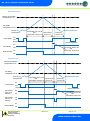
1
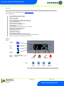
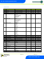
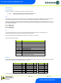
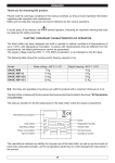
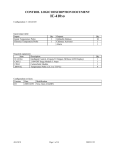
ML Controller PR0123-TWI ML Twin Compressor Controller Installation & User Guide For Products: - PR0710, PR0711, PR0720, PR0721 Resource Data Management Ltd 80 Johnstone Avenue, Hillington Industrial Estate, Glasgow, Scotland G52 4NZ UK +44(0)141 810 2828 Switchboard [email protected] Technical Support [email protected] Sales Enquiries www.resourcedm.com ML Twin Controller Installation Guide Table of Contents: Introduction ........................................................................................................................................................ 3 Display ................................................................................................................................................................ 3 Relay Modules.................................................................................................................................................... 4 Parameter Tables ............................................................................................................................................... 5 Parameter Description ...................................................................................................................................... 6 Setting-up ........................................................................................................................................................... 7 Viewing/Changing Menu Items ......................................................................................................................... 7 Menu Items ...................................................................................................................................................... 7 Inputs and outputs ............................................................................................................................................ 8 Hub/Switch Type .............................................................................................................................................. 8 Case Off / Sec ..................................................................................................................................................... 8 Monitor Probe .................................................................................................................................................... 8 Trim Heater ......................................................................................................................................................... 8 Units .................................................................................................................................................................... 8 Disp .................................................................................................................................................................. 8 Type ................................................................................................................................................................. 8 Relay State and functional operation .............................................................................................................. 9 RTC ................................................................................................................................................................ 10 Network Configuration .................................................................................................................................... 10 Network Compatibility .................................................................................................................................... 10 IP Communications ........................................................................................................................................ 11 Front Panel messages: .................................................................................................................................. 12 Operation: ......................................................................................................................................................... 12 Lead and Lag Compressor Cut-in .................................................................................................................. 12 Lead and Lag Swap Over .............................................................................................................................. 12 Anti Short Cycle ............................................................................................................................................. 12 Single Compressor Operation ........................................................................................................................ 13 Manual Defrost ............................................................................................................................................... 13 Electric Defrost Cycle ..................................................................................................................................... 14 Gas Defrost Cycle .......................................................................................................................................... 14 Network Alarms ............................................................................................................................................... 15 Network Commands ........................................................................................................................................ 15 View I/O ............................................................................................................................................................. 16 Specification: ................................................................................................................................................... 16 General: ......................................................................................................................................................... 16 Relays ............................................................................................................................................................... 17 PART NUMBERS .............................................................................................................................................. 17 REVISION HISTORY......................................................................................................................................... 17 Warning Ensure that all power is switched off before installing or maintaining this product Revision 2.2 Page 2 of 17 www.resourcedm.com Please Note ML Twin Controller Installation Guide Introduction The ML Twin Compressor Controller is a dual stage thermostat with adjustable parameters, incorporating a defrost scheduling timer, lights control, fan control, trim heater control (with energy saving feature by pulsing trim heater) and an alarm handler. The controller can be networked back to an RDM Data Manager, see Network Configuration The main features are: Display with decimal or whole numbers Dual stage thermostat using on/off relays Probe 1: Air On Probe Probe 2: Air Off Probe Probe 3: Logging Probe or Defrost Probe or Plant Fault Probe 4: Logging Probe or Defrost Probe or Plant Fault Programmable parameters Defrost scheduler (up to 8/day) Manual defrost (from the display buttons) Network Defrost schedule option Fan control relay High volume Alarm buzzer Installation (Can be switched off) RS232 output for IP Network connection Automatic compressor duty rotation Network Lights timer function Trim Heater control relay Remote Trim Heater control Remote network commands PT1000, NTC2K, NTC2K25 or 10K probes supported Case Off or Secondary Setpoint Offset option (linked to the lights schedule). Degrees C and Degrees F incorporated in one controller Display LED’s: Cooling Fans Lights Network Off Flashing Steady No network attached Attempting to Log on to network On-line Service Defrost HACCP Alarm Keys Enter Up Down Defrost Note: Function keys illuminate when pressed, illumination is turned off 20 seconds after the key is used. Press and hold the defrost button to force a manual defrost Warning Ensure that all power is switched off before installing or maintaining this product Revision 2.2 Page 3 of 17 www.resourcedm.com Please Note ML Twin Controller Installation Guide Relay Modules The ML controller is supplied in two parts, a panel mount display / control unit and a relay / power supply module in a black ABS enclosure. The two units are interconnected using the 0.75m lead supplied, the control unit derives it’s power from the relay module. All the terminals for power, control relays, networking and temperature probes are contained within the relay module as shown below. The ML controller can be used with a 230 Vac 50Hz or 110V 60Hz mains supply, the switched mains outputs for the relays are fed by the relay module so only one mains supply needs to be connected. 5 Relay module with RS232 connector (for connection to an IP Network) 170mm 75mm 70mm Display Connection 1A Anti Surge Fuse RS232 Comms. Connector Functional Earth Supply Neutral Relay 5 Relay 4 Relay 3 Supply Earth Relay 2 Relay 1 133mm Temperature Probe Connector 149mm Fixing Centre Functional Earth Note: Middle connector not used. Applies to all relays Supply Live 75mm 70mm Probe Common Probe 4 Selectable Connections: NEUTRALS: LIVE: N/C: N/O: Supply Neutral connections Supply Live connections Relay normally closed contact Relay normally open contact Probe Connection Detail Probe 3 Selectable Air Off Air On Probe Common ! All relays will output the supply voltage Note. Earth is a functional earth, not a safety earth Warning Ensure that all power is switched off before installing or maintaining this product Revision 2.2 Page 4 of 17 www.resourcedm.com Please Note ML Twin Controller Installation Guide Parameter Tables No. Parameter P-15 P-16 P-17 P-18 P-03 P-04 Lead Cut-In Lead Diff Lag Cut-In Lag Diff Control Weight Probe 3 Type P-05 Probe 4 Type P-06 Relay 2 Function P-07 Relay 4 Function P-08 Relay 5 Function P-11 P-12 P-14 P-20 P-21 P-22 P-23 P-24 P-25 P-26 P-40 Trim level Anti Short Cycle Time Service Interval Alarm delay Under Temp Alarm Over Temp Alarm Monitor probe Alarm delay Monitor probe Under Temp Monitor probe Over Temp Alarm buzzer duration Defrost Mode P-41 P-45 P-46 Defrost Start Time (Local mode) Defrost number (Local mode) No Defrost Time Defrost Termination Temperature Defrost Time Defrost Type P-47 P-48 Drain Down Time Recovery Time P-42 P-43 P-44 Range OC (OF) Step -60.0 (-76.0) to +60.0 (140.0) -60.0 (-76.0) to +60.0 (140.0) -60.0 (-76.0) to +60.0 (140.0) -60.0 (-76.0) to +60.0 (140.0) 0 to 100 0 = Off 1 = Monitor 2 = Monitor with Fault 3 = Monitor with Alarm 4 = Defrost term 5 = Plant N/O 6 = Plant N/C 0 = Off 1 = Monitor 2 = Monitor with Fault 3 = Monitor with Alarm 4 = Defrost term 5 = Plant N/O 6 = Plant N/C 0 = Fans 1 = Lights 2 = Trims 3 = Alarm 4 = SLV 5 = Trim Hub 6 = Comp 0 = Fans 1 = Lights 2 = Trims 3 = Alarm 4 = SLV 5 = Trim Hub 0 = Fans 1 = Lights 2 = Trims 3 = Alarm 4 = SLV 5 = Trim Hub 0 to 100 00:00 to 99:00 0 to 128 00:00 to 99:00 -60.0 (-76.0) to +60.0 (140.0) -60.0 (-76.0) to +60.0 (140.0) 00:00 to 99:00 -60.0 (-76.0) to +60.0 (140.0) -60.0 (-76.0) to +60.0 (140.0) 00:00 to 61:00 0 = Local 1 = Remote 00:00 to 23:59 0 to 8 0 to 180 -60.0 (-76.0) to +60.0 (140.0) 00:00 to 99:00 0 = Electric 1 = Gas 2 = Off Cycle 00:00 to 24:00 00:00 to 99:00 Units Default C (OF) C (OF) O C (OF) O C (OF) % - 3.0 (37.4) 3.0 (5.4) 6.0 (42.8) 3.0 (5.4) 50 0 1 - 0 1 - 6 1 - 1 1 - 2 1 01:00 1 01:00 0.1 0.1 01:00 0.1 0.1 01:00 1 % mins:secs KHrs mins:secs O C (OF) O C (OF) mins:secs O C (OF) O C (OF) mins:secs - 100 01:00 60 20:00 -2.0 (28.4) 5.0 (41.0) 20:00 -2.0 (28.4) 5.0 (41.0) 00:00 0 00:01 hrs:min 01:00 1 - 6 Hrs C (OF) 12 10.0 (50.0) 01:00 1 mins:secs - 20:00 0 00:15 01:00 mins:secs mins:secs 02:30 30:00 0.1 0.1 0.1 0.1 1 1 1 0.1 O O O Warning Ensure that all power is switched off before installing or maintaining this product Revision 2.2 Page 5 of 17 www.resourcedm.com Please Note ML Twin Controller Installation Guide No. Parameter P-49 P-50 Fan Delay Time Fans in Defrost P-51 P-98 Fan Delay Temperature Lights Control P-81 P-60 Sec Offset Lights Mode P-61 P-62 P-63 P-64 P-65 P-66 P-67 P-68 P-69 P-70 P-71 P-72 P-73 P-74 Dflt Sunday On Time Sunday Off Time Monday On Time Monday Off Time Tuesday On Time Tuesday Off Time Wednesday On Time Wednesday Off Time Thursday On Time Thursday Off Time Friday On Time Friday Off Time Saturday On Time Saturday Off Time Default Settings Range OC (OF) Step Units Default 00:00 to 99:00 0 = Off 1 = On -60.0 (-76.0) to +60.0 (140.0) 0 = Off 1 = Case Off 2 = Sec -60.0 (-76.0) to +60.0 (140.0) 0 = Local 1 = Remote 2 = Manual Off 3 = Manual On 00:00 to 23:59 00:00 to 23:59 00:00 to 23:59 00:00 to 23:59 00:00 to 23:59 00:00 to 23:59 00:00 to 23:59 00:00 to 23:59 00:00 to 23:59 00:00 to 23:59 00:00 to 23:59 00:00 to 23:59 00:00 to 23:59 00:00 to 23:59 01:00 1 mins:secs - 15:00 0 0.1 1 O C (OF) - 0.0 (32.0) 0 0.1 1 O C (OF) - 10.0 (50.0) 0 hrs:min hrs:min hrs:min hrs:min hrs:min hrs:min hrs:min hrs:min hrs:min hrs:min hrs:min hrs:min hrs:min hrs:min 08:00 20:00 08:00 20:00 08:00 20:00 08:00 20:00 08:00 20:00 08:00 20:00 08:00 20:00 00:01 00:01 00:01 00:01 00:01 00:01 00:01 00:01 00:01 00:01 00:01 00:01 00:01 00:01 Parameter Description No. Parameter P-15 P-16 P-17 P-18 P-03 Lead Cut-In Lead Diff Lag Cut-In Lag Diff Control Weight P-04 P-05 P-06 P-07 P-08 P-11 Probe 3 Type Probe 4 Type Relay 2 Function Relay 4 Function Relay 5 Function Trim level P-12 P-14 P-20 P-21 P-22 P-23 P-24 P-25 P-26 P-40 Anti Short Cycle Time Service Interval Alarm delay Under Temp Alarm Over Temp Alarm Monitor probe Alarm delay Monitor probe Under Temp Monitor probe Over Temp Alarm buzzer duration Defrost Mode P-41 Defrost Start Time (Local mode) Defrost number (Local mode) No Defrost Time Defrost Termination Temperature P-42 P-43 P-44 Description The value above which the controller starts the Lead Compressor. The value below the set point at which the controller stops the Lead Compressor. The value above which the controller starts the Lag Compressor. The value below the set point at which the controller stops the Lag Compressor. Percentage of Probe 1 temperature that is used to calculate the control temp and display temp. The remaining percentage will be used on probe 2 temperature. Example, P-03 set to 30% Control temp = 30% Probe 1 + 70% Probe 2 This parameter allows the user to change the function of input 3. See Monitor Probe This parameter allows the user to change the function of input 4. See Monitor Probe Sets the function of relay 2, defaults to Compressor Sets the function of relay 4, defaults to Lights Sets the function of relay 5, defaults to Trims Sets an On percentage level, of a 5-minute period, to pulse the trim heater relay off/on. Example: - P-11 set to 40% = 2 minutes On, 3 minutes Off Time between compressor starts. See Anti-Short Cycle Service interval time, set to 0 then back to reset. Brings on the service (Spanner) icon when active. Sets the OT/UT alarm delay Under temperature Alarm set point Over temperature Alarm set point Sets the monitor probe OT/UT alarm delay Monitor probe Under temperature Alarm set point Monitor probe Over temperature Alarm set point Sets the buzzer on duration when an alarm occurs. Set to 00:00 to not use the buzzer. Defrost mode – Local Mode : Controller schedules P-41 & P-42 Remote Mode : Front-end schedules. Defrost start time for local schedule Number of defrosts per day (local mode) Starts a defrost if no defrost command has been sent for this duration Defrosts terminate when the Air Off/Defrost Probe temp reaches this value (See P-04 & P-05). Warning Ensure that all power is switched off before installing or maintaining this product Revision 2.2 Page 6 of 17 www.resourcedm.com Please Note ML Twin Controller Installation Guide No. Parameter P-45 P-46 P-47 P-48 P-49 P-50 Defrost Time Defrost Type Drain Down Time Recovery Time Fan Delay Time Fans in Defrost P-51 Fan Delay Temperature P-98 Lights Control P-81 Sec Offset P-60 Lights Mode P-61 P-62 P-63 P-64 P-65 P-66 P-67 P-68 P-69 P-70 P-71 P-72 P-73 P-74 Sunday On Time Sunday Off Time Monday On Time Monday Off Time Tuesday On Time Tuesday Off Time Wednesday On Time Wednesday Off Time Thursday On Time Thursday Off Time Friday On Time Friday Off Time Saturday On Time Saturday Off Time Dflt Description Defrost duration, unless terminated by P-44 Defrost type, (Gas type keeps the Comp relay/s active). A period after defrost to allow the draining of any surplus water Recovery time after defrost, OT alarms are inhibited for this period Fans remain off until this time has elapsed or fan delay temperature is reached Fans on or off during defrost; if set to on, they go off at the drain down state and come on after the fan delay Fans stay off until this temperature is reached by the Air Off Probe or the fan delay time expires. Off : Feature not used. Case Off : Places controller in to Case Off Mode when Lights timer is in the off state. Sec : Controller operates from a second offset (P-81) when the lights timer is in off period. See Case Off/Secondary Setpoint Secondary Offset associated to P-98. See Case Off/Secondary Setpoint local : Use the local schedule below. (P-61 - P-74) Remote : Uses a front-end GP timer. Sunday On Time Sunday Off Time Monday On Time Monday Off Time Tuesday On Time Tuesday Off Time Wednesday On Time Wednesday Off Time Thursday On Time Thursday Off Time Friday On Time Friday Off Time Saturday On Time Saturday Off Time Sets all parameters to their default value Setting-up Access to the controller settings can be achieved several ways, Through the display mounted buttons Direct access by PC into the RS232 comms. port. This requires a software package available on the RDM website Through the RDM Data Manager. Across an IP network. (Current controller IP address required) Viewing/Changing Menu Items 1. Press and hold "ENT" and "DOWN" for approx 3 seconds the display will read "EnT" 2. Press and release "ENT", the display will indicate "IO" This is the inputs and outputs viewing option 3. Use the "UP" or "DOWN" keys to cycle round the menu items, press enter at the desired item. . Example: pressing enter at “PARA” will allow you to view or change parameters Note. If menu item "ESC" is entered the controller will escape the set up and revert to normal operation Menu Items IO PArA Unit diSP tyPE Id Rtc Net hub SoFt OFSt rly1 ESC Displays the inputs and outputs View and change parameters Change the Units (Probe Type) Change the display View Controller type Enter an ID (For IP-L Use) Real Time Clock Change the network settings Selects Hub/Switch (Mercury or ML) View the software version Probe Offsets Inverts the operation of Relay 1 Escape back to normal operation Inputs and Outputs Set view parameters Set view units Display Type Set view ID Real Time Clock Network Configuration Hub/Switch Type Probe Offset Invert Relay 1 Warning Ensure that all power is switched off before installing or maintaining this product Revision 2.2 Page 7 of 17 www.resourcedm.com Please Note ML Twin Controller Installation Guide Inputs and outputs Selecting this menu option allows the user to view the inputs and outputs. Use the up/down button to select the desired input or output and then press “Enter”. The value will be shown on the display. See View IO Hub/Switch Type Select the desired value for the type of communication module in use. 0 = Mercury Hub/Switch 1 = ML Hub/Switch Case Off / Sec If “Case Off” is selected the controller will enter “Case Off Mode” when the case lights schedule is in the off period. When case lights schedule is in the on period the controller will follow its normal control operation. This feature is disabled if Temp Cut-In parameter P-01 is set to 4.0 Degrees or lower. Warning use with caution: - Case Off places the controller into a state whereby all outputs are off and alarms are inhibited e.g. no temperature control will occur and no over temperature alarms will be created etc. If “Sec” is selected the controller will operate to a secondary setpoint, using P-81 (Sec Cut-In), when the case lights schedule is in the off period. When case lights schedule is in the on period the controller will operate to its normal Temperature set point (P-01). This feature is disabled if Sec Cut-In parameter (P-81) is set to 4.0 Degrees or lower. Note: The temperature alarm limits do not change so should be set accordingly. Monitor Probe Off Monitor Monitor with Fault Monitor with Alarm Defrost Plant N/O Plant N/C If selected probe is not used. If selected, controller will monitor temperature but will not alarm out. If selected, controller will monitor temperature and alarm out for probe fault but not over or under temperature. If selected, controller will monitor temperature and alarm out for probe faults and over and under temperature alarms. The selected probe will be used as a defrost termination probe (instead of Air Off probe). If selected, controller will generate a Plant fault alarm when the probe input sees a short circuit. If selected, controller will generate a Plant fault alarm when the probe input sees an open circuit Trim Heater Trims: If a relay is configured as Trims then the relay will pulse in accordance with P-11 or will be switched remotely by the Data Manager Trim Control energy feature. P-11 is used if Trim control is not configured in the Data Manager. Trim Hub: If the relay is configured as Trim Hub then the relay is pulsed remotely by the ML/Mercury Switch (PR0109-PHI/PR0018-PHI) Please see the ML/Mercury Switch user documents for further details. Units Use this to select the temperature probe type. 0 = PT1000 (Deg C) 1 = PT1000 (Deg F) 2 = NTC2K (Deg C) (Default) 3 = NTC2K (Deg F) 4 = NTC2K25 (Deg C) 5 = NTC2K25 (Deg F) 6 = NTC10K (Deg C) 7 = NTC10K (Deg F) Disp Display setting: 0 = Decimal display (1 place) 1 = Integer Display Type The twin compressor controller has only one type so cannot be changed. Warning Ensure that all power is switched off before installing or maintaining this product Revision 2.2 Page 8 of 17 www.resourcedm.com Please Note ML Twin Controller Installation Guide Relay Assignment Relay 1 Relay 2 Relay 3 Relay 4 Relay 5 Compressor Note 1 Fans, Lights, Trims, Solenoid Valve, Alarm, Trim Hub or Compressor Defrost (use the N/O for correct operation) Fans, Lights, Trims, Solenoid Valve, Alarm or Trim Hub Fans, Lights, Trims, Solenoid Valve, Alarm or Trim Hub Note 1: Normally relay 1 operation is from the lower HP switch N/C contact, if the higher HP switch N/O contact is required for normal operation, then rLy1 option in the menu must be set from it’s default value 0 to 1. Note: The relay assigned to Trim and/or SLV will indicate the inverse action on the Data Manager value page. Relay State and functional operation Relay State: Relay 1 Off Relay 1 On Function State Compressor 1 On Compressor 1 Off Wired contact N/C N/C Relay 2 Off Relay 2 On Relay 2 Off Relay 2 On Relay 2 Off Relay 2 On Relay 2 Off Relay 2 On Relay 2 Off Relay 2 On Fans On Fans Off Lights On Lights Off SLV or Trims Off SLV or Trims On Alarm Relay = Alarm Alarm Relay = OK Compressor 2 On Compressor 2 Off N/C N/C N/C N/C N/O N/O N/C N/C N/C N/C Relay 3 Off Relay 3 On Defrost control Off Defrost control On N/O N/O Fans On Fans Off Lights On Lights Off SLV or Trims Off SLV or Trims On Alarm Relay = Alarm Alarm Relay = OK N/C N/C N/C N/C N/O N/O N/C N/C Relay 4/5 Off Relay 4/5 On Relay 4/5 Off Relay 4/5 On Relay 4/5 Off Relay 4/5 On Relay 4/5 Off Relay 4/5 On Sample Data manager Screen Shot (Fan Delay state after a defrost) Note: Lights and trims have an extra value to indicate the state (This is the control state, not the relay state) Relay 2 aliased to Fan Control Relay 4 aliased to Lights Control Relay 4 aliased to Inverse trim Control Warning Ensure that all power is switched off before installing or maintaining this product Revision 2.2 Page 9 of 17 www.resourcedm.com Please Note ML Twin Controller Installation Guide ID Sets the controller ID, (normally used in conjunction with the IP-L network mode). Set a number in the range of 1 – 999 RTC Real time clock (This will automatically synchronise on network systems) a. Use the up or down buttons to scroll through the display until the display reads “rtc” b. Press enter. The display will show “t-1”. press enter again c. Scroll hours up or down (0 – 23) press enter d. Use up button to select “t-2”, press enter e. Scroll minutes up or down (0 – 59) press enter f. Repeat for t-3 (seconds 0 – 59) g. Repeat for t -4 (Days up to 31) h. Repeat for t -5 (months up to 12) i. Repeat for t -6 (Year up to 99) j. Use up button to display “ESC”, press enter to display “rtc”. Part Number Description Controller Software Version and IP Communication Compatibility PR0123 PR0123-TWI PR0123-STA PR0123 PR0123-TWI PR0123-STA V2.0–V2.3 V2.0–V2.1 V2.0–V2.1 V2.4 & Above V2.2 & Above V2.2 & Above PR0108 ML IP Module* x X x PR0109 ML Hub* x x x PR0109-PHI ML Hub PHI* x x x PR0016 IP Futura PR0018 Mercury Hub PR0018-PHI Mercury Hub PHI Network Configuration Network Compatibility To log the controller onto a network you must first connect the controller to a suitable IP comms module. Description IP Futura (Single Mercury to IP Interface) Mercury IP Switch (IP support for 10 controllers) Mercury IP Switch with Pressure/Humidity Inputs ML IP Comms module (Single ML to IP Interface) ML IP Switch (IP support for 10 controllers) Mercury IP Switch with Pressure/Humidity Inputs Part Number PR0016 PR0018 PR0018-PHI PR0108* PR0109* PR0109-PHI* When logging the ML controller on to a Data Manager then one of the above communication modules should be used. The ML range of IP communication modules will soon be obsolete with only spares being made available for replacement purposes. For a limited number of software versions the ability to communicate with both the Mercury and ML communication modules has been included in the ML controller software. This revised software will provide compatibility for both ranges for a short time only. Later versions of software will communicate with Mercury communication modules only. The version of ML controller software which communicates with both Mercury and ML communication modules is shown below: * Note software version of the ML IP Module has to be V1.4 or higher. Software versions older than V1.4 are not supported with the revised ML hardware platform. The ML controller has to be set depending on the type of communication module in use. See Hub/Switch Type for further details. Warning Ensure that all power is switched off before installing or maintaining this product Revision 2.2 Page 10 of 17 www.resourcedm.com Please Note ML Twin Controller Installation Guide Network Settings IP Communications There are 2 ways the ML controller can be used with an IP Ethernet network: 1. 2. IP-R IP-L Remote IP address given by the Data Manager (DHCP Server) Local IP address and gateway is set up in the controller. IP-R To use the ML controller in IP-R mode, you will require either a PR0016 Mercury IP Module or PR0018 Mercury Hub. When either of these two devices are used, the rotary switches be given a unique setting. Setting 000 must be avoided for IP-R mode. Once the comms module has been set up and connected to the controller and Data Manager, it will automatically log-on. Once it is online, the IP address given to the controller can be viewed by pressing enter at the “NET” display. Press enter at any one of the submenu option to read the value IP1 = IP address field 1 IP2 = IP address field 2 IP3 = IP address field 3 IP4 = IP address field 4 IP-L To use the ML controller in IP-L mode, you will require either a PR0016 Mercury IP Module or PR0018 Mercury Hub. The rotary switches must be set to 000 on the comms module or 00 on the Hub In this mode the IP address and gateway address must be set up manually in the controller. Use the following table as a guide: - Display Option IP1 IP Address byte 1 IP2 IP Address byte 2 IP3 IP Address byte 3 IP4 IP Address byte 4 nL Network Mask Length (see table below) GT1 Gateway Address byte 1 GT2 Gateway Address byte 2 GT3 Gateway Address byte 3 GT4 Gateway Address byte 4 ESC Exit network menu. N.B. this option must be selected to save any changes made in this menu Setting nL To ease setup, a single network mask length value is used. If the address has been specified with a network mask value in dotted IP format e.g. 255.255.255.0 then the table below gives the conversion: Mask 255.255.255.252 255.255.255.248 255.255.255.240 255.255.255.224 255.255.255.192 255.255.255.128 255.255.255.0 Length 30 29 28 27 26 25 24 Mask 255.255.254.0 255.255.252.0 255.255.248.0 255.255.240.0 255.255.224.0 255.255.192.0 255.255.128.0 255.255.0.0 Length 23 22 21 20 19 18 17 16 Mask 255.254.0.0 255.252.0.0 255.248.0.0 255.240.0.0 255.224.0.0 255.192.0.0 255.128.0.0 255.0.0.0 Length 15 14 13 12 11 10 09 08 The network led will start flashing as the controller is logging on to the network; once logged on, the LED stays on. Warning Ensure that all power is switched off before installing or maintaining this product Revision 2.2 Page 11 of 17 www.resourcedm.com Please Note ML Twin Controller Installation Guide SoFt (Software version) Press “Enter” at this display to show the software version. OFSt Probe offsets: - select a channel (1 - 4) and select an offset +/- 20 OC (68 OF) rLY1 Inverts the operation of relay 1 so that the N/O contact can be used. ESC Press enter at this display to quit out of the menu. Front Panel messages: Typical Front Panel messages: - Display Message Ft Prb1 Prb2 Prb3 Prb4 rec dEF AL OFF System status Control Fault Probe 1 Fault Probe 2 Fault Probe 3 Fault Probe 4 Fault Control State in Recovery Control Sate in Defrost Control State in Alarm (Over or Under Temperature) Controller in Case Off Operation: Lead and Lag Compressor Cut-in The Lead compressor will come on when the control temperature reaches Lead Cut-In set point and will go off when the control temperature reaches the Lead Cut-In set point minus the Lead Diff. The Lag compressor will come on when the control temperature reaches Lag Cut-In set point and will go off when the control temperature reaches the Lag Cut-In set point minus the Lag Diff. Note compressor starts are also dependant on the anti short cycle timer status for the given compressor. There is a fixed 15 second delay from when the lead compressor starts before the lag compressor is allowed to start i.e. if the control temperature rises above Lead cut-In and Lag cut-In rapidly, for example after a defrost, then the lag compressor will come on after a 15 second delay from when the lead compressor started. The valve icon on the display will flash when the lead compressor is running and will be on steady when both compressors are running. The valve icon will be off when both compressors are off. Lead and Lag Swap Over The Lead and Lag compressors will swap after every defrost. For example if Compressor 1 is the lead compressor entering into a defrost then on completion of the defrost Compressor 1 will become the lag compressor and Compressor 2 will become the lead compressor. On first power up of the controller Compressor 1 will be assigned as the Lead with Compressor 2 being the Lag compressor. Anti Short Cycle Once a compressor starts the anti short cycle timer will begin to count. If the time entered for the anti short cycle parameter is exceeded by the time the compressor is turned off it is immediately available for selection if required. If the time entered for the anti short cycle parameter is not exceeded by the time the compressor is turned off then the compressor is not available for use until the remaining anti short cycle time expires. For example if P-12 is set to 5 minutes and the lead compressor starts and runs for 3 minutes before going off then the control logic will have to wait 2 minutes before being able to select the lead compressor for use. If the lead compressor is out of the control logic due to the anti short cycle timer and there is a cooling demand then the lag compressor can still be utilised providing it is not violating its anti short cycle timer. In this instance the Lag compressor would become the Lead and vice-versa until the next defrost. Warning Ensure that all power is switched off before installing or maintaining this product Revision 2.2 Page 12 of 17 www.resourcedm.com Please Note ML Twin Controller Installation Guide Single Compressor Operation If a single compressor is configured then the Lag cut-in and Lag Diff parameters are ignored. Compressor 1 will come on when the control temperature reaches Lead Cut-In set point and will go off when the control temperature reaches the Lead Cut-In set point minus the Lead Diff setpoint. In this operational mode the valve icon will be steady on when the compressor is running and off when the compressor is not running. Manual Defrost Press and hold the "#" key for 3 seconds. A manual defrost in accordance with the defrost parameters will be performed (see defrost page). Warning Ensure that all power is switched off before installing or maintaining this product Revision 2.2 Page 13 of 17 www.resourcedm.com Please Note ML Twin Controller Installation Guide Electric Defrost Cycle Defrost Termination Temperature P-51 Fan Delay Temperature P-49 Control Temperature Comp Relay Termination Time P-45 Drain Down OR Termination Temp P-44 Time P-47 Recovery Time P-48 On Off Normal Operation Fans Relay Defrost Relay Normal Operation On Fan Delay Time P-49 OR Fan Delay Temp P-51 Off On Off Gas Defrost Cycle Defrost Termination Temperature P-51 Fan Delay Temperature P-49 Control Temperature Comp Relay On Off Normal Operation Fans Relay (fans off in defrost) On Fans Relay (fans on in defrost) On Defrost Relay Termination Time P-45 Drain Down OR Termination Temp P-44 Time P-47 Recovery Time P-48 Compressor Stays ON Comp Switches OFF Normal Operation Fan Delay Time P-49 OR Fan Delay Temp P-51 Off Off On Off Warning Ensure that all power is switched off before installing or maintaining this product Revision 2.2 Page 14 of 17 www.resourcedm.com Please Note ML Twin Controller Installation Guide From normal operation, when the defrost sequence starts, the fans are switched off (if fans are set to off in defrost, P-50) and the LLV closes. The controller stays in this state until either the termination time (P-45) expires or the termination temperature (p-44) is reached on the defrost termination or air off probe. The controller then enters the drain down period and the fans are switched off. After the drain down period, the LLV is switched on and the recovery period starts. After the fan delay period or when the fans termination temperature drops below the fans set point (P-51), the fans are switched on. Over temperature alarms are inhibited from the start of the sequence to the end of the recovery time. Recovery ends either when the air off temperature drops below the over temperature alarm level or when the recovery time expires. Network Alarms Alarm text Missed Defrost Over Temperature Under Temperature Log Over Temperature Log Under Temperature Probe 1 Fault Probe 2 Fault Probe 3 Fault Probe 4 Fault Plant Fault 1 Plant Fault 2 Type # (index) 15 4 5 8 9 6 6 6 6 3 3 Network Commands Command Defrost Command Trim Command Setpoint Command Case Off Command Haccp Command Value to send 1 0 to 100% O ±18 C 5 0 0 1 2 Description Initiates a defrost cycle Sets the trim level to this value (Trim period is 5 minutes) Is added to or subtracted from the setpoint Sets the controller to Case Off Restores the controller form Case Off to Normal Conditions Defrost mode: remote Once started defrost terminates on temperature or time Selectable Relay 2/4/5 mode: Trim Heater This command only works when parameter P-98 (Lights Control) Is set to 0 (Off) or 2 (sec) See Note ** HACCP LED OFF HACCP LED On HACCP LED Flashes Note ** When parameter P-98 is set to 1 (Case Off) the lights timer will put the controller into Case Off Mode when the case lights go Off Warning Ensure that all power is switched off before installing or maintaining this product Revision 2.2 Page 15 of 17 www.resourcedm.com Please Note ML Twin Controller Installation Guide View I/O Press “Enter” in the menu at “IO” to view the inputs and outputs. Number I-01 I-02 I-03 I-04 I-05 I-11 I-12 I-14 O-01 O-02 O-03 O-04 O-05 O-06 O-07 O-08 O-09 O-10 O-30 O-31 I/O Control Temp. Probe 1 (Air On) Probe 2 (Air Off) Probe 3 Probe 4 Plant 1 Input Plant 2 Input Hub Trim Level Compressor Relay 2 Defrost Control Relay 4 Relay 5 Lights Trims Fans Compressor 2 Run Time Setpoint Offset Sec Offset Range (dependant on probe type) -60.0 to +60.0 -60.0 to +60.0 -60.0 to +60.0 -60.0 to +60.0 -60.0 to +60.0 0 = Off, 1 = On 0 = Off, 1 = On 0 to 100 0 = Off, 1 = On 0 = Off, 1 = On 0 = Off, 1 = On 0 = Off, 1 = On 0 = Off, 1 = On 0 = Off, 1 = On 0 = Off, 1 = On 0 = Off, 1 = On 0 = Off, 1 = On 0 - 128 -60.0 to +60.0 -60.0 to +60.0 Step Units 0.1 0.1 0.1 0.1 0.1 1 1 1 1 1 1 1 1 1 1 1 1 1 0.1 0.1 O C C O C O C O C O % K Hrs O C O C Specification: General: Supply Voltage Range: Supply Frequency Maximum Supply Current Typical Supply Current Supply Fuse Operating temperature range Storage temperature Operating Humidity Environmental Controller Size Panel Cut-out for Controller Relay Board Size Maximum Weight (combined) Safety (Relay Board) 90 - 270 Vac 10% 50 - 60 Hz 10% 55A <1A 1Amp anti-surge 20 x 5mm +5 oC to 50 oC -20 oC to 65 oC 80% maximum Indoor use at altitudes up to 2000m, Pollution Degree 1 Installation Category II. Voltage fluctuations not to exceed ±10% of nominal voltage 79mm x 37mm x 73mm WxHxD 72mm x 29mm 170mm x 130mm x 50mm LxWxH 1.25kg Class II LVD Safety (Controller) Class II LVD EMC Ventilation Insulation EN61326; 1997 +Amdt. A1; 1998 No requirement for forced ventilation Class I for Relay board Class II for controller Controller only With relays 1 to 5 fully loaded With relays 1 to 5 off load This product is double insulated when used with the original enclosure Only use the cable provided to connect the controller to the relay board. Warning Ensure that all power is switched off before installing or maintaining this product Revision 2.2 Page 16 of 17 www.resourcedm.com Please Note ML Twin Controller Installation Guide Relays IMPORTANT: Some early versions of Relay modules had relays fitted in position 1 that had a lower N/O contact rating (0.5 HP) Look at the label on the enclosure lid for the correct Relay rating. Relay 1 Compressor Relay Note 1 N/O contact 250 Vac / 16A N/O contact 250 Vac / 2HP N/C contact 250 Vac / 16A N/C contact 250 Vac / 1.5HP Resistive Load Motor Load Resistive Load Motor Load Relay 2 Selectable N/C contact 240 Vac / 10A N/C contact 240 Vac / 3A N/O contact 240 Vac / 10A N/O contact 240 Vac / 3A Resistive Load Inductive Load CosФ =0.4 Resistive Load Inductive Load CosФ =0.4 Relay 3 Defrost N/C contact 240 Vac / 10A N/C contact 240 Vac / 3A N/O contact 240 Vac / 10A N/O contact 240 Vac / 3A Resistive Load Inductive Load CosФ =0.4 Resistive Load Inductive Load CosФ =0.4 Relay 4 Selectable N/C contact 240 Vac / 10A N/C contact 240 Vac / 3A N/O contact 240 Vac / 10A N/O contact 240 Vac / 3A Resistive Load Inductive Load CosФ =0.4 Resistive Load Inductive Load CosФ =0.4 Relay 5 Selectable N/C contact 240 Vac / 10A N/C contact 240 Vac / 3A N/O contact 240 Vac / 10A N/O contact 240 Vac / 3A Resistive Load Inductive Load CosФ =0.4 Resistive Load Inductive Load CosФ =0.4 Note 1 Normally relay 1 operation is from the lower HP NC contact, if the higher HP NO contact is required for normal operation, the relay 1 option in the menu must be set from its default value (0) to 1. Damage to relays through out of specification usage will invalidate the warranty. Part Numbers ML Twin Compressor Controller with 5 Relay, RS232 Comms and Screw Terminals: ML Twin Compressor Controller with 5 Relay, RS232 Comms and Screw Terminals (100 Units): ML Twin Compressor Controller with 5 Relay, RS232 Comms and Screw Terminals (20 Units): PR0123-TWI PR0123-TWI-100 PR0123-TWI-20 Each of the above units are supplied with a Controller Display, Display Cable, Relay Board and two PR0240 Probes (NTC2K probe type with a 7 Meter cable) ML PSU Relay module with 5 Relay, RS232 Comms and Screw Terminals: ML PSU Relay module with 5 Relay, RS232 Comms and Screw Terminals (100 Units): ML PSU Relay module with 5 Relay, RS232 Comms and Screw Terminals (20 Units): PR0127 PR0127-100 PR0127-20 Revision History Revision Date Changes V2.2 20/06/2011 New layout and diagrams Warning Ensure that all power is switched off before installing or maintaining this product Revision 2.2 Page 17 of 17 www.resourcedm.com Please Note