1
CAUTION:
Read
RULES
SAFETY
and
INSTRUCTIONS
!
carefully
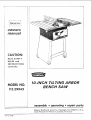
MODEL NO.
113.29943
IO-INCH
TILTING
BENCH SA
assembly
Sears.
and
Part No
62386
Roebuck
Sirnpsons-Sears
. operating
and
Co.,
Chicago,
Lin_it_d.
,, repair parts
IlL
Toronto
60607
U,S.Ao
1. KNOW
YOUR
POWER
10.
TOO[
Read the owner's manual carefully. Learn its application and limitations as well as the specific potential
hazards peculiar to this tool.
2. GROUND
Don't force tool or attachment to do a job it was not
designed for.
I 1. WEAR
ALL TOOLS
3. KEEP GUARDS
13. SECURE WORK
IN PLACE
Use clamps or a vise to hold work when practical. It's
safer than usingyour hand, frees both hands to operate tool.
and in working order.
4. REMOVE ADJUSTING
WRENCHES
KEYS AND
14.
Form habit of checking to see that keys and adjusting
wrenches are removed from tool before turning on tool,
5. KEEP WORK
AREA
CLEAN
DANGEROUS
ENVIRONMENT
AWAY
WORKSHOP
16. DgSCONNECT
DON'T
or by
TOOLS
before servicing and when changing accessories such
Qs blades, bits, cutters.
KID PROOF
master switches,
TOOLS iN TOP
Keep tools sharp and clean for best and safest performance. Follow instructions for lubricating and
changing accessories.
All visitors should be kept a safe distance from work
area.
--with padlocks,
starter keys.
OVERREACH
15. MAINTAIN
CONDITION
Don't use power tools in damp or wet locations. Keep
work area well illuminated.
7. KEEP CHILDREN
DON'T
Keep your proper footing and balance at all times.
Cluttered areas and benches invite accidents.
9.
USE SAFETY GLASSES
Also use face ordust mask if cutting operation is dusty.
third prong.
8. MAKE
PROPER APPAREL
No loose clothing or jewelry to get caught in moving
parts.
12.
6. AVOID
USE RIGHT TOOL
17. AVOID
removing
ACCIDENTAL
STARTING
Make sure switch is "OFF"
FORCE TOOL
18.
It will do the job better and be safer at the rate for
which it was designed.
before plugging in cord.
USE RECOMMENDED
ACCESSORIES
Consult the owner's manual. Use of improper accessories ma'/ be hazardous.
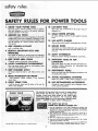
The operation of any
objects
being thrown into the eyes, which can result in severe eye
damage. Always wear safe_ glasses or eye shields before
commencing power tool operation. We recommend Wide
Vision Safety Mask for use over spectacles, or standard safety
glasses.., available at Sears retail or cata og stores
THIS SAFETY SEAL OF THE
POWER TOOL INSTITUTE ASSURES YOU...
®
I. That the manufacturer's
power tools, including
the particular tool
associated w;_h the Seal, are produced in accordance with applicable
Standards
For
National
2,
That
Safety
Standards
€omplloncu
of
Underwriters'
laboratories
and
American
(AI_SI).
with
applicable
safety
standards
is assured
dependent inspection and testing conducted by Underwriters"
tories (UL).
3,
That
every
motorized
4.
That
every
tool
rules
for
5.
Copyright
1969 by Power
Too] instifute,
inc.
AI| righ?s reserved.
That
the
has
t0o!
with
protection
of
the fool rnanufadurer
is a sponsor
of the
is inspected
it adequate
Instltute's
the
under
by
in-
Labora-
power.
instruct|ons
and
a
llst of
safety
user.
is a member
of the
Consumer
Safety
Power
Tool
Education
Instffute
Prog ram.
and
SASWTY INSTRUCT|ONS
TO OP£RATOR
has started
WARNING:
Do not connect power cord
until _he following
steps have been
satisfactorily completed:
a. READ CAREFULLY AND UNDERSTAND THE FOLLOWING INSTRUCTIONS and the "SAFETY RULES
FOR POWER TOOLS" ON PAGE 2.
b. Examination and operating familiarity with ON-OFF
switch, elevation control, bevel control, miter gauge,
and rip fence.
d. Always
e.
6. A
4. Kickbacks can cause serious injury. A "kickback" occurs
when a part of the workplace binds on the saw blade or
binds between the saw blade and the rip fence or other
fixed object, risesfrom the table, and is thrown toward
the operator. Kickbacks are usually caused by one or
more of the following conditions:
a. Failure to use a spreader when ripping, or failure to
maintain the spreader in alignment with the saw
blade.
b. Improperly conditioned (dull) saw that permits the
material to pinch on the out-feed edge of the saw
and rise from the table.
5. Injury from kickbacks can be prevented
or minimized
by:
a. Avoiding
any of the causes noted above;
b. Making sure by trial before starting the cut that the
anti-kickback pawls will stop the kickback once it
goggles.
large
proportion
of tilting
and miter gauge
arbor
dur-
saw accidents
is
injury
by proper cutting
7. Gloves should not be worn while operating
the saw.
Loose flowing
garments,
jewelry
(rings, wrist watches,
etc.), and neckties should never be worn. Long sleeves
should be roiled to above the elbows.
8. To protect your eyes, always wear safety goggles.
In
addition,
wear a face shield to protect
against flying
particles.
Ear protectors (ear plugs or muffs) should be
used during extended
periods of operation.
9. Provide proper support for the workpiece, based on its
size and the type of operation to be performed;
hold
the work firmly against the gauge or guide. Use a push
stick when ripping short work (under 6-inches fang), or
marrow work. A push block or mi_r gauge hold-down
should be used when dadoing or molding.
10, Never use a length stop (such as the fence when crosscutting) on the free end or edge of the workplace. Never
hang onto or touch the free end of workplace,
or a free
piece that is cut off, while power is "ON"
and/or
the
sawblade
is rotating.
In short, to guard
against kickbacks or other potential
accidents, the cut-off
piece in
any thru-sawing
operation
must never be confined
it
must be allowed
to move lalera!ly.
Never use the rip
fence when cross-cutting,
or the miter gauge
when
ripping.
d. Ri0ping wood that has a twisted grain, does not
hove a straight edge to guide along the fence, or
wood that is twisted or not flat (which may rock on
the table and pinch the blade).
g. Releasing workpiece before operation is complete;
not pushing the workplace all the way past the saw
blade.
safety
Never use both the rip fence
ing the same operation,
THE SAW OFF. Avoid potential
tool and machine maintenance.
c. Failure to determine that the rip fence and the saw
blade are parallel to one another.
e. Confining the cut-off piece when ripping or crosscutting.
f. Ripping by applying the feed force to the section
of the workpiece that will become the cut-off (free)
piece (feed force when ripping should always be
applied between the saw blade and the fence -- use
push stick for narrow or short work).
wearing
out of line of
the switch ON
the materia{ to stick, jam, stall the saw, or kick-back at
the operator. Cracked saw blades should be discarded
immediately.
A saw blade can become cracked
if it
wobbles or if it is not in balance. NEVER ATTEMPT TO
FREE A STALLED SAW BLADE WITHOUT
TURNING
1. The saw should be baited down if there is any tendency
to tip over or move during normal operations. The
saw table should be approximately
36-inches above
the floor.
3. The saw should be positioned so neither the operator
nor o casual observer is forced to stand in llne with
the sow blade.
all points if they do not);
caused by dull, badly set, improperly filed cutting tools,
by gum or resin adhering to cutting tools and by fence
misalignment
(out of parallel).
Such conditions
cause
CAUTION: Always disconnect the power
cord when removing the table insert,
changing the cutting too{, or making
adjustments.
2. The saw work area should have adequate overhead,
non-glare light and adequate surrounding work space.
(sharpen
c. Keeping your face and body always
possible kickbacks,
including turning
and OFF.
1 I.
Cross-cutting
operations
are more conveniently
worked
and with greater
safety if an auxiliary
wood facing is
attached
to the miter gauge using the holes provided.
12.
Do not leave a long board
unsupported
so the spring
of the board causes it to shift on the table. A support
should be used to catch the end of the board behind the
blade.
13.
Never
climb
with power
a complete
14.
Avoid
on or near the saw. Never
on, or before
stop.
awkward
the cutting
operations
and
leave
the saw
tool has come to
hand
positions, where
a sudden slip could cause a hand to move into a saw
blade or other cutting toot. Never reach in back of the
cutting tool with either hand to hold down the workpiece.
(Continued
an Next
Page)
safety instructions to operator
15. Make sure the top of the arbor or cuffing tool rotates
toward you when standing in normal operating position.
Also make sure the cutting tool, arbor collars and arbor
nut are installed properly. Keep the cutting tool as law
as possible for the operation being performed, Keep
all guards in place whenever possible.
piece of wood or other object works around to the rear
of the revolving blade. It can usually be avoided by removing all loose pieces from the table immediately
after they are cut off, using a long stick of wood, and
by keeping the guard and spreader in place at all times.
Use extra caution when the guard assembly is removed
for dadoing or molding, and replace the guard as soon
as that operation is completed.
]6, Do not use any blade or other cuffing tool marked for
an operating speed in excessof the design speed of the
saw. Never use a cutting tool larger in diameter than
the diameter for which the saw was designed. For
greatest safety and efficiency when ripping, use the
maximum diameter blade for which the saw is designed,
since under these conditions the spreader is nearest
the blade,
]7.
Adjust table
table top.
inserts flush with,
Or slightly
below,
21. Never perform any operation "freehand."
This term
............
the stock into the saw blade or other
cutting tool without using the miter gauge, rip fence,
taper jig, or some other device which prevents rotating
or twisting of the workpiece during the operation.
22. Never turn your saw "ON" before clearing the table
of all objects (tools, scraps of wood, etc.) except the
workpiece and related feed or support devices for the
operation planned.
the
18. For operations which do not permit the use of a spreader, serious consideration should be given to the use of
jigs or fixtures to hold the work so the hands of the operator ore removed a safe distance from the point of
operation. (See the booklet "How To Do More _,Nith
Your Bench Saw.")
23. Safety is a combination of operator common sense and
alertness at all times when the saw is being used.
24. Do not cycle the motor switchon and off rapidly, as this
may cause the saw blade to loosen. In the event this
should ever occur, allow the saw blade to come to a
complete step and retighten the arbar nut normally, not
excessively.
19. The use of abrasive or cut-off wheels, or wire wheels
can be dangerous and is not recommended. (Abrasive
or cut-off wheelsare used to saw many different materials including metals, stone, and glass.)
\!VARNENG:
Do not
(gained from frequent
became commonplace.
that a careless fraction
ficient to inflict severe
20. Objects can be thrown upward toward the operator by
the back of the blade if proper operating procedures
are not followed. This usually occurswhen a small loose
allow
familiarity
use of your saw) to
Always remember
of a second is sufinjury.
CONTENTS
Unpacking
and Pre-Assembly
Motor Specifications
Operating Controls
Instructions
and Mounting
....................
...
.......
Page
5
Proper
14
19
Accessories ...............
Repair Parts .........................
TOOLS
Operating
Procedures
.
Page
20
25
26
NEEDED
Screwdriver (medium)
Screwdriver (small)
7/16-inch wrench
1/2-inch wrench
9/16.inch wrench
Square (combination square, try square, or both)
Pencil
-_,,._
Rubber
mallet
4,
,_.r,-1.
j-. ,,,
Small steel scale
v
HARDWARE
_ls_utu_
RIEQUIEEO
_
IF
SAW
IS TO lie MOUNTED
(TWO
ON
OF EACH
BENCH
OR
I_EQUIEED)
TASBE
ware required to attach the saw to a bench
or table is not supplied. (Two 3/8-inch diameter bolls; length determined by thicknessof table top; four 3/8-inch flat washers;
arid two 3/8-inch nuts.l
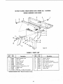
unpacking
and pre-assembJy
UNPACKINGAND PR[°A$SEMBLY
INSTRUCTIONS
UNPACKING
AND
CHECKING
CONTENTS
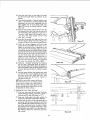
This Craftsman Bench Saw is shipped
(without motor).
complete
in one carton
in order to prevent damage during shipment and facilitate
packaging, certain items have been removed
at the factory
and must be assembled when received
by the purchaser.
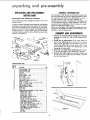
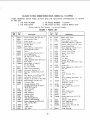
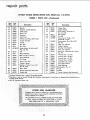
Remove all items from the package
and identify them by
referring to figure 1. These "'loose" parts are listed below
and should be accounted for before discording
any packing
material
(See
figure
GENERJ_L
INFOIIMATION
The instructions in this manual are presented in step-by-step
order and illustrated
by numerous pictorial diagrams. Read
the instructions
and observe the illustrations
to insure a
correctly
assembled
and accurately
adjusted saw.
Adjustments
are carefully
checked prior to packaging
the
saw for shipment; however, rough handling in transit may
necessitate some readjustments.
For this reason all adiustmerits are presented
in logical order.
Reference to the Repair Parts exp|oded drawings (and item
listings) may be helpful in acquiring a more thorough understanding
of your Craftsman saw.
Assr BLY AND ADJUSTMENTS
1.)
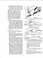
1.
Remove the rust-preventive
coating from external
surfaces
(saw table, etc.) with a cloth moistened with
kerosene.
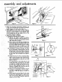
:2. _nstail
the
tilt
hand-wheel
secure it by tightening
on tilt screw
the set screw
shaft
and
with a 1/8-inch
hex-L wrench.
(See figure 2.) Use pliers on the hex-L
wrench and tighten the set screw on the "flat"
of tilt
screw. Exercise care against
damaging the hand-wheel.
LOOSE
Key Ha.
(Fig. 1)
1
Z
3
4
5
6
7
8
9
10
11
12
13
14
15
16
17
PARTS
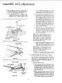
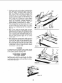
4.
Remove
the table
insert, by inserting a finger into
the slot at one end of the insert and lifting it upward
and out. (See figure 3.)
(I/8-1NCH)
T [LT
Guard Assembly-Saw .........................
Fence Assembly-- Rip ..........................
Operating Instructions ..........................
Handbook ....................................
Wrench, Arbor ................................
Gauge Assembly - Miter ........................
Rack - Table .................................
Bar Assembly -- Fence ........................
Bag of Loose Parts ............................
Hand-Wheel Assembly, Tilt 4-1/2 in..............
V-BelL 1/2 x41 in..............................
Pulley--V, Single Groove,2.1/2x5/8
in. Bore ....
Support Assembly - Motor ......................
Rod Assembly-Splitter
........................
Support Assembly - Splitter .....................
Guard, Belt ...................................
Clamp, Ring ..................................
Contentsof LooseParts Bale-- (Key No. 9, above)
Wrench, Hex-L,3/32 in.........................
Wrench.Hex-L 1/8 in.........................
Wrench,Hex-L, 5/32 in........................
Wrench,flex-L, 1/16 in........................
Bolt, Carriage, 5/16-t8 x 3/4 in................
NuL Square, 5/16-18 .........................
Washer, 11/32 x7/8 x 1/16 in.................
Loekwasher, 5/16 x .125 x .078 in. ..............
Screw,Mach., Rex Hd., 5/16.1S x5/8 in..........
Spacer, Fence Guide Bar ......................
Screw, Mach., Rd.-Rd.,Slotted, 1/4-20 x 2 in......
Nut, Flex. t!4-20x7/16x3i]6
in..............
Lockwasher,!/4x.109x.062
in...............
Screw, Mach., He×-ln-Hd. 5/16-18 x I in.........
Key (for Switch Lock) .........................
Grommet ...................................
Clip, Cord ..................................
1
1
!
]
1
I
]
]
]
1
]
1
!
1
1
]
1
1
1
1
4
4
4
4
2
3
3
3
3
2
2
]
2
avoid
Rotate the tilt hand-whee|
clockwise
until it stops,
to set the saw blade in the vertical (90 °) position.
HEX-L WRENCH
Qty
to
3.
LIST
Part Heine
over-tlghtening
HAND-WHEEL
\
Figure 2
adiustrnents
EL_VAT iON
fl_D-WHE
/
EL
.REAR
OF
SAW
{ NUT
F_u_
4
ii
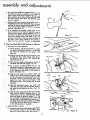
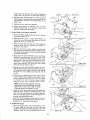
5. Rotate the elevation hand-wheel
clockwise until
it stops. This will position the saw blade at maximum
height (deepest cut) position. (See figure 4.)
6. Check tightness of saw arbor nut by wedging a
small block of wood between the saw blade and table
opening, as shown in figure 5, and, using the arbor
wrench supplied with the saw, tighten the nut. (The
nut rotates clockwise to tighten.)
7. Adjust Stop Collars as Follows:
a. Checking and Adjusting the O° Position....
(1) With the saw blade in deepest cut position,
check the tilt position of the saw b|ade by attempting to rotate the tilt hand-wheel clockwise
until it will rotate no farther.
(2) Place a square on the table top and against saw
blade. (See figure 6.) The blade should be at
exactly 90 degrees (perpendicular) to the tabletop surface. (Make sure the square is resting
against the flat surface of blade and is not
being held away by the "tooth-set" of the blade.)
(3) if the blade is not square with table top, rotate
the tilt hand-wheel counterclockwise until the
tilt mechanism movesa short distance away from
the stop collar on tilt screw. When the pointer
on tilt scale indicates approximately 10 degrees,
the stop collar can be reached. (See figures 7
and 9.)
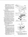
(4) Loosen the two set screws in the stop collar,
located on the tilt screw nearest tilt hand-wheel,
with a small screwdriver and rotate the stop
collar counterclockwise at least one turn. (See
Two slotted-head set screws (figure 8) are used
in each stop collar so that one of the screws
will always be accessible (with operator reaching inside the saw base from the rear of saw,
figure 9)_ After adjusting the collar, it is only
necessary to tighten one of the set screws to
secure the Collar on the tilt screw.
(5) Rotate the tilt hand-wheel clockwise until the
saw blade is perpendicular to the saw table--
(6)Reach inside of saw base (figure 9) and rotate
the stop collar clockwise until it is in firm contact
with the saw cradle. Tighten one of the stopcollar set screwsenough to keep the collar from
rotating on the tlit screw.
Figure 6
SET
_H
/_
T,LT
SCREW
I
- SCREW
_
0_ POSITION
COLLAR
STOP "
T_LT
____
SET
SCREW
Figure
Figure
I
8
(7) Rotate the tilt hand-wheel counterclockwise approximately three turns, then rotate it clockwise
until it stops. Check the saw again with the
square as shown in figure 6. If the adjustment
is correct (blade square with table surface),
tighten the set screw in the stop collar securely.
NOTE: Several trial adjustments may be required in order to produce an accurate
adjustment of the stop collar. If the first trial
fails to produce an accurate setting, it is suggested that the operator determine which
direction the stop collar needs to be rotated
for a correction and turn the collar in small
increments (checking each time) until the
adjustment is correct. Be sure to tighten one
of the collar set screws after each adjustment
to prevent the collar from slipping on the
tilt screw when it comes into contact with the
saw cradle.
\
(8) With the tilt hand-wheel rotated clockwise until
it stops (saw blade 90 ° with table surface),
check the tilt pointer on tilt gauge which should
be at exactly "0" (zero) degrees. (See figure 10.)
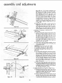
A close look will show a reflection of the pointer
tip on the mirror surface of the tilt scale on front
panel. In order to make sure that you are sighting
squarely with the scale, move your eye until the
tip of the pointer and its reflected image coincide.
(9) If the pointer is not aligned with the "0" mark,
bend the pointer carefully with pliers (figure
10) until it remains at "'0" when the pliers are
removed.
b. Checking and Adjusting
I!_1 TILT
scREw
c.
the 45 ° Position.
fl ) Rotate the tilt hand-wheel counterclockwise
it will rotate no farther.
f
until
Figure
(2) Remove the scale from a combination square
and place the head of the square on table top
and against saw blade. (See figure 1I.) The saw
blade should be setting at exactly 45 degrees
with table top surface.
(3) Efthe acute angle between saw blade and table
top is not 45 degrees, rotate the tilt hand-wheel
clockwise until the tilt mechanism moves a short
distance away from the stop collar (located
farthest out toward the end of tilt screw, figure
12) so the collar can be reached for an adjustment. When the tilt scale indicates approximately 35 degrees the collar will be accessible.
(4) Loosen the two set screws in the stop collar. (See
figures 8 and 12.) If, in preceding step (2), the
blade stopped with the acute angle greater than
45 degrees, rotate the stop collar counterclockwise (toward end of tilt screw). If the angle is
less than 45 degrees, rotate the collar clockwise
(away from end of tilt screw). For each trial
setting: move the stop collar a short distance
away from saw cradle (by rotating tilt handwheel clockwise) loosen set screw, rotate the
stop collar a fraction of a turn in desired direction, tighten one of the set screws (figure 12)
and rotate the tilt hand-wheel counterclockwise
until it stops. Then measure the angle of saw
blade with table surface, as shown in figure 11.
12
TABLE INSERT
Figure
I3 _
Several trials will probc_bly
be required
duce an accurate
stop at the 45-degree
to proposition.
(5) Tighten one of the stop
collar
set screws securely
a{ter the adius_.ment has
been
completed.
NOTE: If the above
accurately
performed,
a positive
the pointer
positions.
stop at "0"
adjustments
the saw
and
on tilt scale
"'45"
a,
Install
Table
Insert
the table
have been
now have
degrees
should
(6) Rotate the tilt hand-vcheel
"0'" position,
as indicated
Adjust
will
and
stop at both
until it stops at the
by the pointer.
as Follows:
inser,_ by"
sliding
position and pressing down
firmly
the spring clips on under'Side
of
position. (See figure 13.)
it carefully
into
at both ends until
insert "snap"
into
assembly and adiustments
S_ING
CLIP
,711
c. Wffh the table insert in place, use a small scale or
straightedge to check near each of the four set screw
positions, in order to determine if the table
ins_ert is
even with saw table surface at all four set screw
positions.
(See figure 15.)
d. If an
adjush_p_nt is _ry,
rotate
each
of
(See figure 15,) Make sure that ends of al! four
screws are making conrad with table recess
9. Align
Saw Blade With Table Grooves os
the
set
by
F_|aws:
a. Checking for Correct Alignment.
(I)
Check elevation and tlh hand-wheels to make
sure each is rotatad fully cleclcwisa -- to position
saw blade for deepest cut and sc!uare with
(2) Make n mark at _
of one _
of b|ade just above table su_ce.
16.) Select a tooth that is set
right-hand side of saw.
tooth at rear
(Se_ figure
toward
the
(4) Lay a pencil, or similar pointed tool, in the
depression lust ahead of miter gauge scale, with
pencil point toward Hie blade and hold pencil
in the depression with thumb of left hand as
shown. (See figure 163
15) Slide the miter gauge to a position which will
poi_t the pencil at the marked saw tooth. Hold
a small scale against the marked tooth and slide
the pencil toward the saw until the point rests
against the scale. With the left thumb,
hold
the pencil securely in miter gauge head. it must
n(Mt mQ_.
(6) With the right hand, remove the scale and
rotate the saw blade until the marked tooth is
just above the saw table at the front, (See f_gure 17.)
(7) Slide the miter gauge toward the front of saw
table untll the pencil is pointing 1owardl the
m_ed
tooth. Insert the _le
between
Pencil
point and blade, as _hown in f',gure 17. If ti_
saw is parallel to table groove, the scale will
just slide into the gap _n
the pencil point
and blade. If the sca|e will not enter, or is lOOSe
in the check Shownin figure 17, an adi ustment
b.
of the table trunnions is required.
Adiusting Table Trunnions.
(l)
Loca_ lbe three screws which secu_'eeach (front
//'-
Figu 14
permit each trunnion to "'stip ' when tapped with
a mallet or plastlc-tipped
hammer. (If loosened
completely,
it would
be almost impossib_e to
achieve an accurate
Qdiustment. )
(2) Shift the two trunnions by
until the two measurements
FENCE
GUIDE BA!R
topping
them lightly
described in the pre-
ceding instructions are equal. Tighten the trunnion screws and recheck measurements
to make
sure tightening
screws did nat a_ter the setting.
Several trials may
accurate setting.
be
required
to produce
an
@
10. Ins_'ali the Table Rack,
a. Position the table rack against
lower edge of fence
guide bar so that rack teeth are on upper edge of
rack and pointing
outward.
Align the three ho_es
in both parts. (See figures
19 and 20.)
b.
Insert
one
of
the
three
1/4-20
x 2-inch
RACK
\
_ LC)CKWASHER
\
fl!4
SCREW
NUT
(HEX.,
screws
(I/4-20 × 2 _o.)
I/4-20)
through holes at one end of rack and guide bar and
place a guide bar spacer on the end of the screw.
(See figure 19.) Insert the screw through
the saw
table and install a 1!4-inch
!ockwasher
and 174-20
hex nut. Do not tighten
c.
Instalt the remaining
ers and nuts. Rotate
the
screw at this time.
until they are snug. Do not tighten
11.
Check
and
Adiust
FENCE
GUIDE
two screws, spacers, Iockwashthese three screws into their nuts
the
Rip
Fence
TEETH
them at this time,
TABLE RAC K
as Follows:
Your Craftsman
Rip Fence has been designed to provide accuracy,
reliability
and long llfe. In order for
your fence to work properly,
it is imperative that it be
adjusted accurately. The fence is adjusted at the factory, but due to shipping hazards,
and s_ight tolerance
buildup
between individual
saws, it is sometimes necessary that your fence be adjusted to your particular
saw.
Therefore,
check your fence and adjust it (if necessary)
as outlined
in the instructions
that follow:
;REW
(1/4-
20 x 2 iN.)
Figure 20
i
i
CAUTION:
It is imperative that these instruc_
;'ions be followed
precisely, as an incorrect
adiustment
could damage
the fence and the
fence guide bar attached
to your saw.
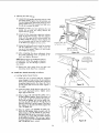
a.
Installation
(1)
of Rip Fence.
Raise the lock handle
and position the rip fence
on the saw table, Do not latch the lock handle.
Lower the saw blade
beneath
the table surface
by rotating
clockwise.
the elevation
hand-wheel
counter°
LOCKWASHER
12) Slide the rip fence atong the guide bar while
watching the clearance
between
lower edge of
fence and table top. if any portion of the fence
(except
sliding
pad
at
rear)
drags
(3)
this adjustment-
Tighten the 1/4-20 × 2qnch screws securely and
recheck to make sure tightening
these screws did
not affect
the guide
bar
setting.
_
on the table
top, or if clearance
between
fence and table top
vades appreciably
as the fence is moved, the
guide bar must be adius ted. This is accomplished
by tapping
the guide bar slightly
up or down
with a soft mallet until a consistent clearance
exists over entire top surface of the table. The
screw holes in guide bar and table have sufficient clearance
around
the attaching
screws to
permit
( I/4 IN.
b.
Adjusting
Pinion to Rack.
(1) Check for correct engagement
(mesh) of teeth
on fence adjusting
shaft pinion with the gear
teeth in lower edge of rack. (See figure 21.) The
pinion should be adiusted
up or down so that
assembly and adjustments
gear teeth are in full contact lengthwise and
meshed as far as possible, just short of binding.
This adjustment is made as follows: Push the
fence adjusting knob all the way down, and
look underneath the rock to determine if the
pinion and rack teeth are aligned. (See figure
21.) If the pinion extends too far (or not far
enough) loosen the set screw (1, figure 221 with
a 5/32-1rich hex-L wrench and slide the knob
assembly on the pinion shaft (up or down) to
achieve proper alignment. Tighten the set screw
(1, figure 92).
Figure
(2) Adjust gear mesh (depth of tooth contact) by
loosening the set screw (3, figure 22) with a
5/32-inch hex-L wrench and rotate the eccentric (4, figure 22) untll proper mesh is obtained.
Tighten the set screw after adjusting. Check for
proper operation at various points along the rack.
22
c. Checking for Parallelism of Rip Fence with
Table Groove.
(1) With the lock handle released {not latched), slide
the fence on the saw table so the front end of
the channel is flush with the side of one of the
two miter grooves. (See figure 23.) This can be
checked by using your fingers as shown to "'feel"
for correct alignment. Shift the rear of the fence
to the right or left slightly, causing fence not to
be square with the front edge of the table, nor
parallel to the miter groove.
Figure 23
(2) Push down on the lock handle carefully (do not
force) while watching the rear of the fence for
-,
,
'
CAUTION: Do not force the lock handle.
If the handle does not lock down readily,
an adjustment is necessary -- and to force it
could cause damage to both the fence and
its correcting
adion.
guide bar.
(3) The lock handle should lock in the clown position.
._
-!
for the handle to be all the way down to lock
the fence. (See figure 24.) The rear of the fence
Do not force the handle, as it is not necessary
should move to correct itself, and do so parallel
I'flush) with the miter groove in saw table throughout its full length. Alignment may be checked
with the forefingers to determine if the fence is
flush with the side of miter groove, as shown in
figures 23 and 24.
(4) tfthe lock handle responded as described above,
and the fence aligned itself with the table groove
at both enas, the fence is properly odiusted and
no further attention is necessary. If not, perform
the following adjustment routine.
_'_
Figure
24
d. Adjusting the Rip Fence Parallel to Table Groove.
(1) Remove the fence and turn it over. Then, with a
1/8-inch hex-L wrench, loosen the pawl set screw,
located just behind the fence pawl, approximately twotums. (See figure 25.)
(2) Using a 5/32-inch hex-L wrench, loosen the set
screw at the rear of the fence approximately
two turns. (See figure 26.) This screw is located
in thefence lock just inside the channel, as shown.
10
(3)
Place the
fence
that the lock
position.
(4)
back
handle
on saw table
offers
Place the lock handle
and
no resistance
in "locked"
notice
at any
position, and,
using a 1/8-inch
hex-L wrench inserted into the
fence-pawl
set screw from underneath the saw
table, tighten the set screw finger tight. (See
figure 27.) Do not use wrench or pliersfinger
tight only.
15) Raise the lock handle, push the fence to one side
(off square) at the rear. Then lock the fence with
the lock handle, while watching to make sure it
"corrects"
itself. Repeat this operation
two or
more times. The fence should "'correct" itself
each time it is locked.
(6)
Raise the lock handle and align the fence with
the miter groove (at the front end of the groove)
as shown in figure 23. Push the lock handle dawn.
17) Check for
groove for
aligned at
rear, loosen
the channel
correct
the full
the front
the two
near the
Figure
alignment
with saw table
length of the fence. If it is
but out of alignment
at the
hex-head
screws on top of
front (figure 28) just enough
to permit the channel to slip when tapped lightly
with the palm of one hand. Tap the channet at
the rear of the fence with one hand until it is
aligned with the table groove. Tighten the two
hex-head
screws securely
and recheck.
More
than one triat may be required,
as tightening
the screws may change the setting slightly.
(8)
Check for "automatic
correcting"
by releasing
the lock lever, shifting
the fence off square at
the rear, then locking it. The fence should square
itself automatically
and be flush (parallel)
with
the miter groove each time the handle is locked
down,
(9)
Lock the fence with the lock handle, and, using
a 5/32-inch
hex-L wrench, tighten the fence lock
set screw at the rear,
hand tight only. (See
figure 29.) Make sure the fence is "secure"
to
the table at the rear.
NOTE: If the fence fails to square itself everytime, check for any burr or foreign
material
on the surface
of the fence head where it
contacts the saw table. Also check for nicks
Figure
29
or burrs in edge of saw table_ Stone off any
irregularities
on these surfaces.
e.
Aligning
Rip Fence
Plastic
l
indicators.
(1) If for any reason the tilt hand-wheel
has been
rotated during preceding
operations,
rotate it
clockwise until it stops (tilt pointer at "O").
FENCE
(2)
Raise saw blade
above the table surface
rotating
the elevation
hand-wheel
clockwise
by
(3)
Position the rip fence on the right-hand
side of
saw blade with the fence channel one inch from
the saw blade and lock the fence. Be sure to use
one of the teeth bent (set) to the right of blade
and measure from this tooth to the fence, since
this determines your width of cut. (See figure 30.)
This distance
should be measured
accurately
with a scale.
Figure
11
30
'
27
adiustments
(4) Set the right-hand indicator (a scribed line in
the plastic window) to "'1" inch on the guide-bur
scale, This is accomplished as follows:
yeu are sighting squarely above the scale,
move your eye until the indicator line and its
reflected
image coincide. (See figure 31.1
(a) A close look will show a reflection of the
indicator
line on the mirror surface of the
guide-bar scale. In order to make sure that
(b)
If an adiustrnent is required,
loosen the two
screws cone at each end of the window]
and
shift the plastic window
untit the indicator
line is aligned with the "'!" inch line on the
scale, fSee figure 32.) Tighten the two screws
and recheck for accuracy.
If the plastic window cannot be shifted far enough to provide
this alignment,
loosen the screws that secure
the guide-bar
scale to the gulde-bar
at its
ends, shift the scale slightly and tighten the
screws. Then proceed
to adjust the plastic
window as described above.
SCALE
(WITH MIRROR
(c)
SURFACE)
WINDOW
When the fence is correctly
adjusted
and
moved to any position at the right of the saw
blade, the scale will indicate the width
of
the desired cut. Make several trial settings
and check by measuring with a scale from
the fence to the blade.
NOTE: When
properly adjusted, the indicators may be used for most operations,
thus
eliminating
the need for actual
measurements, except
for extreme
requirements.
When sighting the indicator, always use the
system shown in figure 31 in order to make
sure the sight angle is correct.
REFLECTEDIMAGE
Figure
31
(d)
I ND ICATOR
IN
PLASTIC
LINE
Move the fence
blade
and
(right-hand
WINDOw
!
same manner
NOTE: Remember,
to the left-hand
side of saw
adjust the left-hand
indicator
side of fence channel)
in the
as for the right-hand
indicator.
if the scale must be moved
when adjusting
the left indicator,
it will
change your settings on the right-hand
indicator which was previously
set.
(5) Remove
the
interference
12.
$CREWS
Figure
Check and Adjust
rip fence
from
the
saw
with subsequent adjustment
the Miter
Gauge
to
avoid
routines.
as Follows:
The miter gauge was set at the factory. During shipment, however,
rough handling
might have disturbed
32
the setting, To assure maximum accuracy the "0"
degree stop should be checked
and adjusted
quired) as follows:
(zero)
(if re-
LOCK HANDLE
ROD ASSEMBLY
SQUARE
a, Checking
STOP
PIN
the Miter
Gauge.
(1) Loosen the lock handle and push stop pin firmly
into the middle detent ("0"" position on the scale).
The stop pin will be seated more effectively if it
is rotated slightly as it is being "pushed"
into
the detent. Tighten the lock handle firmly hand
tight, (See figure 33,)
(2) Using a combination square, check for an exact
90-degree angle between the miter gauge and
rod assembly. If this measurement is exactly 90
degrees, the adjustment has not been disturbed
and the gauge is-ready for use. If not accurate
at 90 degrees, adjust the gauge as follows:
INDICATOR
BLOCK
Figure 33
12
b. Adiusting
(1)
the Miter
Gauge.
Loosen the lock handle, disengage
stop pin, hold
the square soLid{_ against the rod assembty a*._d
face and tighten lhe Jack handle firmly by hand
Always tighten the tack handle hand fight o_ly.
Do not use a wrench
or pJiers_
(2)
Recheck to make sure that tightening
the iock
handle
did not alter
the setting. Remove the
square from the gauge.
(3)
Loosen
the two screws that
attach
the indicator
block to the rod assembly.
Shift the indicator
block until the stop can be pushed solidly
into
its detent. Hold the indicator
btock aligned
with
the rod assemb{_/and the stop pin seated firmly
in the detent and tighten the two screws.
C'EWHE*t L
(4) Loosen the lack handle and recheck for accuracy
with the combination
square.
(Make certain the
stop pin is fully seated.)
Tighten the Jack handle
and readjust if necessary.
(5) After completing
the above adiustment,
the pointer
attaching
screw, set pointer
(zero) and tighten
the screw.
NOTE:
Detents at the two 45-degree
are jig bored.
for 90-degree
are
(6)
13.
lnstaq!
a.
{1J
Figure
34
""
_oasen
at "0"
positions
When the gauge is adjusted
cut, the 45_degree
positions
col'root.
Remove the miter gouge
from saw tabJe until
remaining
checks have been completed.
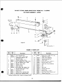
Saw Guard
Installing
(1)
5/,6
Splitter
Assembly
BJede
PIN
TER SUPP©RI
\
as Follows:
Bracket.
Install
the two 5/16-18xSi8-inch,
hex-head
screws laosemy in holes at rear of saw cradle as
these screws cannot be installed
after attaching
the splitter blade bracket_ (See figure
are the screws thai secure the motor
340 These
support in
the cradle.
(2)
tnstaH the splitter b;ade
18xl
inch box-head
finger
(3)
tight
bracket
screws.
with two 5/16Tighten
screws
at this time.
Refer to figure 35 and hold the splitter rod to
the left of splitter support_ Rotate the splitter
rod
so the "flat"
on the rodis toward the operator.
Then slide the spJiffer rod into the spfitter support from the left until the pin (through the rod)
bottoms in the slots in splitter support. (See figure
35.) Tighten
"'flat'"
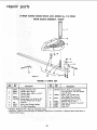
(4)
the thumb
af splitter
screw firmly
against
the
rod.
Slide the splitter
rod (attached
to splitter support) into the sp{iii'er
blade
bracket
until the
splitter blade is directly behind the saw blade.
(See figure 36.) Do not be concerned if the splitter bar does nat align with saw blade vertically
as this will be Corrected
in the next step. "lFighten
the socket-head
set screw in splitter
with a 5/32-inch
he×-L wrench.
\
blade bracket
13
motor specihcat ons and mounhng
ore
i
o
screws (figure 371 that attach the splitter blade
bracket to saw cradle. Sight along splitter bar
and saw blade again after tightening these
screwsto make sure alignment was not disturbed.
(5) With saw blade all the way up, MAKE SURE IT
IS 90 ° OR SQUARE WITH THE TABLE. Raise the
blade guard and by using a square, adjust the
spl_r
vertically 90 ° (Square) to the table.
Tighten the two 5/16-18 x 1-inch screwsto secure
thesplitter blade bracket to the cradle. Place a
large square or straight-edge alongside the
saw blade. If the splitter is not in line with the
saw blade, loosenthe sockethead set screw (See
figure 36) and move the splitterassembly to the
right or left so that it touches the square and is
in linewith the saw blade (See figure 37). Tighten
the set screw.
NOTE: After the splitter blade is properly
aligned, always remove the guard by loosening the thumb screw _figure 35) and sliding
the assembly off the splitter rod. This will
avoid upsetting any of the alignment adjustments, as the pin in the splitter rod will serve
as a "stop" when the guard is installed.
CAUTION: When cleaning the plastic guard
is necessary, wipe surfaces with a clean, dry
cloth. Do not use solvent of any kind.
(6) Recheck to make sure the following screws are
tight:
The socket-head set screw Cfigure 36) that secures the splitter rod, and the two hex-head
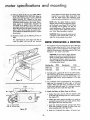
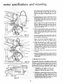
MOTORSPECIFICATIONS
& MOUNTING
1. This Craftsman Saw is designed for use with a 3450 rpm
motor. The saw arbor has a 2-1/2-1nch diameter pulley
attached and a 2-1/2-inch diameter motor pulley is supplied for driving the saw at the proper speed of 3450 rpm
through a 1 to 1 motor to saw ratio.
_-_
_,ivl
./"/
?_
CAUTION: Do not install a larger diameter
pullev on the motor as it would drive the saw
blade at speeds which would be dangerous.
The following Craftsman motors are recom.
.
mended, available at any Sears Retad Store
or Catalog Order House:
0
J
_¥E
Catalog
/
/
-
J_:_
_'_
_l
No.
t:
/
_'_
/
I
_
/
_'_
Fiaureg 37
Horsepower
99KT121 c 3450
99KT1220C
/
RPM
10120
3450
fi_r wil°l!imt
_fP_it
_
Vo|ts
1
110-120 or 230
aab_r_:t_ c_mmu
::ddehda
mn°_gteP"
cl°t:s
figuration that will not permit installation of the belt
guard.
i
__l_
3. The Craftsman motors recommended in the preceding
table may be connected for either right- or left-hand
rotation. Make sure that wiring connections are made
so the motor shaft will rotate in a clockwise direction
BLADE
_7
(when facing the drive end). (See figure 38.)
4. Attach the Motor to Motor
BELT GUARD
Base as Follows:
a. Position the motor with the 5/8-inch diameter shaft
at the right with mounting base in a vertical position.
(See figure 39.)
\\
b. Positionthe motor support assembly as it would be
oriented if mounted on the saw cradle, with the motor
base against the motor mounting base.
c. Insert four 5/16-18 x 3/4-inch carriage bolts (from
loose parts package) through the motor base and
motor mounting base. (See figure 39.)
use 5/B
END OF
Figure
38
d. Instal! an 11/32-inch flat washer, 5/164nch
14
lock-
washer and 5/16-18 square nut on each carriage bolt
finger tight. (All parts are in loose parts package.)
LOCKWASHER
THESE TWO
(5/16 iN)
EDGESEVEN
CARRIAGE BOLT
(5/16-I_3/4
iN.)
e. Shift the motor mounting base on motor base until
the top edges of each are even and carriage bolts are
approximately
centered in the slotted holes of the
motor base.
f. Tighten the four square nuts securely.
g. install shaft guard on left-hand end (1!2-inch
diameter) motor shaft, if not already in place. This
guard is supplied with the motor.
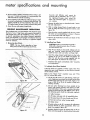
5. Install
Motor and Support Assembly.
a. Position the blade slightly below the deepest cut position end tilt pointer at "'0",
Figure
39
b. Install the motor pulley on motor shaft with the set
screw boss toward the outside. (See figure 39.) Do not
tighten the set screw at this time.
c. Place the drive belt over the saw arbor pulley by
reaching inside saw base, allowing it to hang temporarily on this pulley.
MOTOR &'OUNT
d. Slide the two pins on motor support assembly into
their holes in saw cradle far enough to enable the belt
to be placed in the groove of motor pulley. Raise blade
to deepest cut position.
e. Grasp the motor with both hands as shown in figure
40 and lift up until the pivot arm screw is at the rear
of the slot, as shown. While holding the motor in this
position pull it rearward (toward operator) until the
drive belt is "snug" and tighten the two motor mount
clamp screws securely. The pivot arm screw should
still be at the rear of limit of its slot.
MO]OR
f. Release the motor and note that it remains at essentially the same position as it was held. The motor base
will probably rotate slightly rearward, thus leaving
the pivot arm screw slightly away from the end of
its slot.
g. If the belt is _ot aligned with the two pulleys, which
can be readily seen by sighting along edges of both
pulleys, slide the motor pulley in or out an the shaft
as required and, when correctly aligned, tighten
pulley set screw with a 5/32-inch hex-L wrench.
NOTE: If correct pulley alignment cannot be
obtained by the preceding method, loosen the
square nuts on motor base, shift the motor
in desired direction and tighten the nuts.
h. Loosen the motor base clamp screws (both ends) and
rotate the motor so that the ventilation holes in the
shell of the motor are facing down and the capacitor
cover is on top (See figure 41). This will help prevenl
sawdust from entering the motor.
i. Lower the blade enough to permit removal of drive
belt from the arbor pulley and remove the belt in
preparation for installing the belt guard.
6. Install
Belt Guard.
a. Place the guard clamp ring around right-hand end
of motor, slide the free end into the screw-type
fastener. (See figure 42.) While holding the two ends
together, rotate the screw in fastener with a screw-
Figure 42
15
PULLEY
Figure
40
and rnounfin
driver./Cake sure the screw engages the openings in
the ring and rotate the screw until the clamp ring
diameter just leaves enough clearance on motor
frame for the guard to be slipped easily under the
ring.
Hold the belt guard as shown in figure 43 and insert
the drive belt into the guard as shown. The lower end
of belt should contact the inner wall of the guard
so it will pass over the motor pulley when the guard
is slipped into place.
h.
Slide the guard on end of motor, while holding it as
shown in figure 44, and slide the clamp ring over
the edge of guard leaving edge of ring approximately
1/2-inch from edge of guard. Do not tighten the
clamp ring at this time.
BELT GUARD
d. Grasp the belt between
thumb and
shown in figure 44 and, while looking
CLAMP
forefinger
as
down into the
guard "hook"
the lower loop of belt onto the motor
pulley. Shift the guard on motor to center
the belt
in the guard.
RING
e.
Continue to hold the belt on motor pulley, rotate the
guard downward and "'hook"
upper end of belt onto
the saw pulley inside the base.
f.
Rotate the elevation hand-wheel clockwise until it
stops, to place the saw blade in its highest position.
g. Positionthe belt guard so the belt clears the inside
of the guard at the upper position approximately
1/4-inch and the guard does not touch the underside of saw table. (See figure 45.) Correct positioning
of the belt guard is important. If the belt should be
permitted to rub against the guard it would soon
wear a s|ot in the guard.
h. Tighten the clamp
on motor.
i.
ring
to
hold
the
guard
securely
Rotate the elevation hand-wheel counterclockwise to
lower the saw blade tothe lowest position and check
positionof guard, The beh should still clear the inside
of the guard.
7. Adjusting
Pivot Arm Screw.
This adjustment (figure 46) is necessary to prevent motor
vibration (screw too loose) and to permit the motor mount
to maintain correct belt tension whenever the saw blade is
raised or lowered with the elevation hand-wheel (screw
too" fight if belt tension is not maintained). When either of
these conditions are evident, adjust the screw as follows:
MOTOR POWER CORD
S
CAUTION: Do not tighten the pivot arm
screw to a locked position, as it would be
sheared off when the saw blade is raised.
a. Tightening or loosening the pivot arm screw (figure
MdTOR
Figure 45
16
PIVOT-ARM
SCREW,
AND
_iER
FLAT WASHER
Figure
-MOTOR
46
BASE
BELT GUARD
Figure 47
b. Apply a few drops of oil (SAE 10 or 20] to the flat
washer and in slot in motor base, and adjust the screw
in small increments until the motor base slides readily
in or out in response to blade elevation movement
throughout the full range.
GROMMET
c. After obtaining normal movement of motor bose,
observe the saw in operation after starting it as described in subsequent instruction. If the motor base
tends to vibrate, tighten the screw a little at a time
until vibration is minimized. After eliminating vibration recheck as in preceding step b, to make sure the
base will still slip in response to blade elevatian
movements.
8. Connect and Position Motor
Power Cord.
a. Feed the motor power curd through the large hole in
saw base. (See figure 44.)
\
b. Grasp the connector on end of motor power cord
and, while looking into the base, insert the plug into
the receptacle at rear of switch box. (See figure 47.)
c. Position the power cord as shown in figure 47, and
install two cord retaining clips on edge of saw bose
flange to secure the cord. Locate clips at approximate positions shown. Allow approximately 12 inches
of cord between the motor and saw base,
\
Figure
REAR OF
48
BASE
d. Hold the power cord and slide the grommet (on cord)
up to the base and insert it into the hole in base panel.
(See figure 48.)
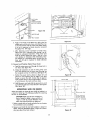
MOUNTmNG
SAW
ON
BENCH
Some usersprefer to mount the saw solidly by bolting it to
a bench or table top. The following method for mounting
the sow is recommended.
23-1/2
CAUTION:
Make sure the saw mounting surface of bench or table is even and free of
"'twist" in order to prevent distortion of saw
table when mounting bolts are lightened.
1. Select a sturdy table or bench and plan the saw location
for convenience
and accessibility.
2. Measure
and mark
the two hole
locations
in bench
(or
table), using the dimensions shown in figure 49. [Dimensions are given from hole centers.)
Figure
17
49
i
motor specifications and mounting
3, Drill two holes in table at marked locations. Holes in saw
base are 7/16-inch in diameter. It is recommended that
3/8-inch bolts be used for mounting.
Accurate and effective work cannot be
achieved with a dull blade. The saw arbor
has right-hand threads which causes the
arbor nut to become tighter in response to
saw rotation.
4. Cut an opening in the table top undersawbase, in order
to prevent accumulation of sawdust inside the base. The
opening should be at least 12-inches, The actual size
will depend upon the type of table or bench being used.
5. Mount the saw with proper length bolts.
PERIODIC
MAINTENANCE
a.
b. Slide a wedge
tooth to wedge
figure 50.)
OPERATIONS
This Craftsman saw is a fine machine and should be given
the best of care. If kept clean andproperly lubricated, it
will provide many years of trouble-free service. There are
no specific maintenance time tables. However, operations
listed and described in paragraphs immediately following
should be performed when conditions or symptomssuggest
need for attention.
1. Removing
Remove the table insert, as described
bly and Adjustments".
under "'Assem-
shaped block of wood under a saw
the blade and prevent rotation.
CSee
c. Using the arbor wrench supplied with the saw, rotate
the arbor nut counterclockwise to loosen it Remove
the nut and loose collar with fingers.
d. Remove the wood block and slide saw blade off the
arbor shaft.
2. Installing
Saw Blade.
Saw Blade.
CAUTmON: Under no circumstances should a
blade with a diameter greater than 10 inches
be used with this saw.
NOTE: The saw blade, regardless of type
being used, should be kept sharp at all times.
a.
Slide the new blade on arbor shaft, making sure saw
teeth are "'pointing'* toward the front of saw table.
install the loose collar and arbor nut finger tight.
b. Insert the wedge
shaped
wood
block into the table
opening at the rear of saw blade and tighten the
arbor nut with the arbor wrench supplied wlth the
saw. (See figure 51.1 Remove the wood block.
ARBO_ WRENCH
WOOD BLOCK
c. install the table insert as described
and Adjustments".
under "Assembly
3. Lubricate Saw When Needed.
Lubricant should be applied to friction points when they
appear dry upon visual inspection,or when friction increases
on the various controls.
Ref er to the '_ Repair. Parts" exploded
List" for correct item names.
views and "Parts
a_ The tilt and lift screws are self-cleaning, which preventsclogging or gummingof the threads, as the sharp
threads w_pe and clean the gear teeth. Apply a few
drops of SAE 20 or 30 oil as needed to keep parts
Figure 50
b. The saw arbor bearings have been packed at the
factory with proper lubricant and require no addirotating smoothly.
tional lubrication. Other parts requiring lubrication
should be oiled frequently with SAE No. 20 or 30 o I.
The following parts should be lubricated regularly:
(1) Table trunnions.
(2) Lift screw and gear rack of assembled arbor.
(3) Tilt screw block, tilt screw threads and tilt nut.
WOOD BLOCK
(4) Pivot pin and saw arbor housing guide.
(5) Clamp screw.
c. All points where a slip fit is necessary for adjustment
purposes should be oiled occasionally. (Pivot arm
screw, for example, figure 46.)
/
d. Attention should be given to moving parts in the rip
fence and miter gauge for cleanliness and lubrication.
Figure 51
1B
operating
controls
e. To prevent the saw table surface from rusting, it should
be kept covered with a film of Sears "Stop Rust" when
not in use. It can be wiped off with a cloth before
using. Treat other unpleted and unpainted parts and
surfaces with "Stop Rust".
MITER
SAW
RIP-FENCE
LOCK HANDLE
GAUGE
OPERAT NG
CONTROLS
FENCE
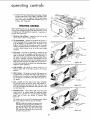
Before operating the saw, the operator should examine all
controls until thoroughly familiar with their functions, as well
as making sure that mechanisms respond to operation of
controls. (See figure 52.)
1. Elevation Hand-Wheellocated on the front of the
saw to raise or lower the saw blade.
2.
Tilt Hand-Wheel
control
-- located
on left-hand
the angle of tilt. The saw blade
HAND
WHEEL
#
SWITCH
ELEVATION
HAND WHEEL
Figure 52
side of saw to
can be tilted from
0 to 45 degrees, as indicated on the Tilt Scale. If the
angle of cut (tilt) must be extremely accurate, the angle
of the saw blade should be checked with a protractor,
or with a board known to be cut at the exact angle
required.
3.
Rip Fence-the
fence is operated
by pushing in the
Fence Knob so that it engages a pinion gear with the
teeth on the Rack. Turning the knob after pushing it in
will cause the rip fence to move across the table. When
the knob is released,
it becomes disengaged from the
pinion gear and the rip fence can be moved across the
table by hand. Keep the saw table and rip fence clean,
as dirt may prevent the rip fence from assuming proper
alignment
when tightened.
4.
5.
Lock Handle--this
fence in place after
position.
handle
is used to clamp
it has been moved to the
Miter
gauge
Gauge
this
is used in table
Figure 53
the rip
desired
grooves
as
a guide far the work-piece. The angle of the gauge can
be adjusted by loosening the clamp handJe and positioning the gauge as indicated
by the dial and pointer on
the gauge.
6.
7,
Key-located
at lower right of saw base, alongside
the ON-OFF switch, to lock the switch and prevent unauthorized
persons turning on the saw. The key must
be in the lock before the ON-OFF switch can be turned
on. (See figure 53.)
ON-OFF
Switch
switch lever is
protection. It is
under
end of
figure 54.)
Figure
54
Figure
55
-- also at lower right of saw base. The
of unique design for maximum safety
turned "on" by inserting the forefinger
lever and
pulling
it outward.
[See
The switch can be turned
off by thumb
KNOB
RACK
pressure (figure
55) or by striking it with any part of the body.
NOTE: At this point, plug in the power cord,
insert the key and turn itto the unlocked position and pull the ON-OFF switch lever outto
start the saw (figure 54.) Turn off the ONOFF switch by pressing the lever inward (figure 55) to stop the saw.
SWITCH
19
LEVER
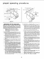
proper operating
procedures
PUR_£
P OPEROPEEATJNG
PROCEDURES
COLOR
RIP
CUTS
DEPTH
OF
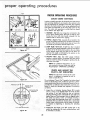
CONTROLS
In order to simplify operation of this bench saw, basic set-up
and operating adjustments are keyed to the controls to be
used in performing the operation with color discs applied
directly to the item involved. These set-up adjustments and
color-codes are illustrated on the front (trim) panel of the
saw. The colors and operations to which they are keyed
are as follows: (See figure 56.)
CUT
ORANG[
LOCK
CODED
1. ORANGE-Rip Cuts. An orange disc is located in the
end of fence locating knob. This knob is used for positioning the fence (with lock handle released)
for the
desired width of board when ripping.
UflLOCK
2. PURPLE--Depth
of Cut. A purple disc is located in the
end of the handle attached to the elevation
hand-wheel.
Rotation of the elevation hand-wheel raises or lowers the
saw blade to provide the desired
MITER
3.
tIGHT
BLUE
depth of cut.
CUTS
v'ELLOW
LIGHT BLUE--Bevel
Cut. A light blue disc is located
in the end of the handle attached to the tilt hand-wheel.
Rotation of the tilt hand-wheel
at the desired angle with saw
Figure 56
positions the saw blade
table for the bevel cut
required,
The angle is indicated by the pointer
tilt scale (located on front panel).
4. YELLOW-Miter
Cuts.
The
miter
gauge
on the
indicator
(pointer) is colored
yellow. The pointer and miter gauge
scale are used for setting the gauge to produce the desired -niter cut angle.
NOTE: For additional
descriptions of controis involved in the use of the saw, refer to
the paragraph
"OPERATING
CONTROLS".
CHECK AND
EXACT-I-CUT
NOTE:
This adjustment
ADJUST THE
gNDICATOR:
is listed at this point
since it is necessary TO operate
order to make the test.
Figure 57
the saw
in
The cut indicator ("Exact-I-Cut') located a few inchesahead
of the saw blade (figure 57), enables the operator to determine preciselywhere the cut in a particular board will occur,
provided the cut indicator shoes have been correctly positioned, it should be checked and adjusted (if necessary)
as follows:
i,
WIDTH OF CUT-_
SOC KET-HEAD
rSCREWS
CUT INDICATOR
1. Inspect the cut indicator housing (figure 58) to make
sure it is even or just slightly below the level of table
top surface. If too high, locate the two cut indicator
housing attaching screwsunderneath the saw table and
fig hten them until the housing is flush (or slightly below)
the table top surface. If the cut indicator housing is
too 10w, loosen the attaching screws until it is correctly
positioned. (The cut indicator housing has a spring.type
washer under it which permits it to be raised, or lowered,
in response to ffghtening or loosening the attaching
screws.
CUT-INDICATOR
Figure
SHOES
2. Position the saw blade in the 90 ° position (0 °
scale), by rotating the tilt crank counterclockwise
it will rotate no farther.
58
2O
on tilt
until
3.
With the saw running, place a straight board (preferably
hardwood) against the miter gauge and hold it securely.
4. Make a smaff cut and pull the miter gauge back until
the cut is directly on the "Exact-l-Cut".
(See figure 57.)
If both cut indicator shoes are aligned with the edges
of the cut, no adjustment is required. If not aligned,
loosen the two socket, flat-head screws with a 1/16-inch
hex-L wrench and slide the cut indicator shoes laterally
until the edge of each shoe is aligned with its respective
edge of the cut in the board. (See figure 58.) Tighten
both screws and recheck for accuracy of the adiustment.
GUARD
./
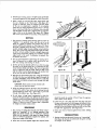
RIPPING
Figure
The process of sawing wood with the grain is known as
"ripping".
it is generally done with the aid of a rip
fence as a guide to positio_ and maintain the work at
correct width for the desired cut. (See figure 59.) Since
the work is pushed along the fence, it must have a reasonably straight edge to make sliding contact with the
fence. Also. work must make solid contact with the table,
so that it will not wobble. Provide a straight edge, even
if this means temporarily nailing of an auxiliary straight
edge board to the work. If workpiece is warped, turn
the hollow side down.
59
:USH STICK
i-INCH
SQUARES.
/"
2. The saw guard should be used during all ripping operations. The guard has a splitter which prevents the saw
kerr from closing and binding the blade.
3. Set the rip fence to desired width of cut, either by using
the scale on the fence guide bar, or measuring the distance between blade and fence. The fence _sgenerally
used on right-hand side of blade. Stand a little to the
right of center to avoid being sprayed with sawdust and
to be clear of work in case of a kickback.
Figure 60
Figure
61
I
4. Start the saw and advance the work, using the left hand
to hold work down and right hand to push it forward. As
:ut nears completion, move the left hand to a safe distance from saw blade, and push work through with right
hand a Eone.
CAUTION: Never reach in back of blade with
either hand to hold work down.
When the distance between the fence and saw blade is
less than the width of your palm, do not attempt to push
work through by hand. Use a push stick or pull work
through from behind saw. (See figure 60.)
RIGHT
WRO
Figure 62
Do not leave a long board unsupported so that the
spring of the board causes Jt to shift on the table. Use a
support to catch end of board behind the blade. If board
is quite long, use another support in front of saw blade.
(Figure 61 shows one type of support that is adjustable
for height and easily constructed.)
I
F'g
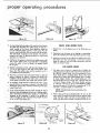
should be made to overlap 112-inch from the approximate center of the board.
3. If the first cut is too deep, the kerf will close and bind
the saw on the second cut, with danger of kickback. Also,
when the kerf closes, the two sidesof the cut are no !anger
parallel to the saw blade, and the saw wilt cut into them
to spoil their appearance. (See figure 62.)
RESAWING
1. The process of cuffing thick boards into thinner ones is
known as "resawing". It is a ripping operation. (See
figure 62.) Small boards (up to 3-3/B-inch maximum
width) can be resawed in one pass, but larger boards
(up to 6-1/4-inch maximum) require two passes, one
along each edge of the board.
_,. Keep same face of board
both cuts.
against fence when making
CROSSCUTTING
1. Sawing wood across the grain is known as "'crosscuffing".
(See figure 63.) Boards are milled with the grain running
the length of the board.
2. When two cuts from opposite edges are required, these
21
proper
operating
Figure
procedures
64
Figure
65
BEVEL AND
2. In crosscutting the long edge of the work is placed across
the table top, therefore, the miter gauge is used as a
guide instead of the fence. Most operators prefer to
use the left-hand table groove. In this case, the left
hand is used to h_]d the work in contact with the gauge.
The right hand is placed on the handle and used to
advance the work. If right-hand groove 'is used, hand
positions are reversed.
MITER
THE DADO
HEAD
1. The dado saw or head is a special set of blades for
cutting grooves and dodos with a bench saw. (See figures
68 and 69.) (Dado heads may be purchased at any
Sears Retail Store or Catalog Order House.) The head
consists of two solid, stiff outside blades, and a number
of inside chipper blades. The outside blades are 1/8inch thick; there is one 1/4-inch, two 1/8-inch, and one
1/16-inch chipper blades. With these blades, grooves
of I/g-inch, 1/4-inch can be cut and additional widths
increased in stepsof 1/6-inch up to a maximum of 13/16inch and a maximum depth of 1-3/8-inches.
6. An auxiliary wOOd extension bolted to the miter gauge
greatly improves the gauge as a support. (See figure 65.)
Sandpaper glued to the extension will help prevent side
creep of thework.
NOTE: Outside bladescan be used alone, chippers cannot.
7, If the work overhangs the saw table enough to sag al
each end, provide supportsthe same as in ripping operations. The stop rod on the miter gauge, or a stop block
fastened to the extension, is used to fix position of
left-hand edge of Work for measuring length of piece
to be cut off. (See figure 66.)
2. When using a full set of dado blades, do not use the
loose collar. The width of the dado can be reduced while
using the loose collar and two or more passes can be
made with the work to obtain the desired width of cut.
SAVV
/4"CHt PE -
,
C H IPPERS ARRANI _GED
_/,_TO
_OF
FALL
IN
GULLETS'z
OUTSIDE SAWSII_
V/ Z_ co,,
' _I r-_
Figure
67
Figure 68
the saw
3. Miters are crosscutsat an angle to the edge of the work.
(See figure 67.) The miter gauge is set at the required
angle to make the cut. Here also, precautions must be
taken to prevent creep.
5, Start the cut slowly and hold work firmly to table to
prevent kickback or chatter. (Loosely held pieces will
sometimes vibrate against the table wher_ crosscutting,
which tends to bind the saw blade and dull the teeth.)
_
CUTS
2. Operations are the same as for ripping or crosscutting,
but work should be extra well supported to prevent creep.
4. Square crosscutting is done with the miter gauge set at
"0" (at o right angle to the slide and groove). (See
figure 64.) The splitter need not be removed, but it is
not needed for this operation.
OUTSIDE
66
1. Bevels From 1 to 45 degrees are cut by tilting
blade.
3. Ordinarily, the gauge is placed in the table groove with
bar in front. When work is so wide that it completely
covers the table in front of blade, the gauge should
be reversed.
I/E"
Figure
RAKER
TOOTH
22
TEETH
Figure
69
3. A dado insert must be used to replace the standard table
insert. When using a full 13/16*inch dado set, the arbor
cannot be tilted to 45 degrees without touching the
insert. Do not attempt to operate in this position. Also
when the dado is set for the maximum depth of cut
(1-3/8-1nches), be sure to spinthe blade by hand before
turning on the motor to make sure the blade does not
strike the dado insert. Whenever two or more chippers
are used, stagger the swaged ends as evenly as possible
around the circumference. Fractional adjustments in
thickness of the head can be made by using paper
washers between the outside blades and chippers.
4. Dado head operations are much the same as those with
a standard blade. Since the dado head takes a larger
bite, the work should be held more firmly. It is a good
practice to use a hold-down jig like the one shown in
figure 70.
Figure
70
5. When a groove wider than the dado head is required,
make two or more passes, The best method is to use a
notched stop block to position each successive cut. (See
figure 71.) The block is fastened to edge of table where
it can be used to position work before starting the cut,
but in a position that will not permit contact with work
during the cutting operation. Space the cuts so they
overlap slightly.
6. When cutting a gain (a groove that is closed at one end)
use a stop block to fix the end of the cut. (See figure 70.1
To locate the stop, place the work alongside the dado
head in position in which it will be when cut is finished.
Then rig the stop at the end of the work. When cuffing
a stopped groove (which is closed at both ends) also use
a starting block, as shown in figure 72. This is located
in same manner as the stop block,
Figure
71
SANDING
A sanding wheel can be mounted on the saw arbor and the
tilting arbor of the saw" provides a high degree of versatility
for fine sanding operation.
(See figure 73.)
STABmL|ZmNG WASHERS
FOR THmN BLADES
Stabilizing washers should be used only with thin blades.
When using these washers, the maximum depth of cut cannot
be obtained and the washers must be kept below the bottom
surface of the table insert.
Figure 72
Figure 73
23
//
procedures
BEARING
RETAINER
NSIDE|
SAW BASE
\
Figure
74
\
Figure
RELOCAT|NG
THE TnLT HAND-WHEEL-FROM
LEFT SIDE TO RIGHT
SIDE OF SAW
2. instai_ing
75
Parts on Right-Hand
Side. (See figure 75.)
a. Insert the inner end of tilt screw through the hole in
right-hand side of saw base (figure 75) then reach
inside of base and slide the inner bearing retainer
on the tilt screw, with flat face of retainer toward the
tilt screw bearing. Start the stop collar on the threads
and rotate it a few inches onto the tilt screw.
The design of this saw permits relocation of the tilt handwheel by moving it from the left-hand side to the right-hand
side of the saw. Should the operator prefer this hand-wheel
on the right, the change maybe made as follows:
NOTE: Figures 74 and 75 show only the saw
base. The table and cradle have been left
out for darity.
b. Start the end of tilt screw into threads in saw cradle.
c. Continue to rotate the tiff screw clockwise into saw
cradle, while at the same time rotating the stop collar
outward on tilt screw, until the outer end of flit screw
emerges from the hole inside saw base. it may be
necessary to grasp the saw cradle and tilt it by hand
enough to permit the outer end of tilt screw to pass
through the hole and emerge into the base.
1. Removal of Partsfrom Left-Ha nd Side. (See figu re 740
a. Loosen the set screw intilt hand-wheel with a 5/32inch hex-L wrench and remove the tilt hand-wheel
from end of tilt screw. (See figure 74.)
b. Reach inside saw base from the rear and loosen two
set screws in each stop collar just enough to permit
the stop collars 1o rotate easily on tilt screw
c. Remove the stop collar located near the end of tilt
shaft.
d. Slide the outside bearing retainer onto the tilt screw
(oriented so it wilt fit the bearing contour) and rotate
the tilt screw counterc!ockwise until the end passes
through the hole in the base.
d. Remove two No. 10 x 7/1 6-inch pan-head screwsthat
secure the bearing retainers to the saw base with a
screwdriver.
e. Work the outside bearing retainer into position on
the bearing and inside the base and siide the inside
bearing retainer over the stop cellar and into position
on the bearing.
e. Grasp 1he saw cradle by reaching nsde the base
from the rear end flit" the cradle until the end of
tiff screw is withdrawn into the base. The tilt bearing
shims will fall out and should be retrieved as they
must be re-lnstalled on the opposite side.
f.
f. Slide the outsidebearing retainer off end of tilt screw
and tilt the cradle by hand (while guiding the end of
tilt screw into the hole) until the outer end of tilt screw
passes through the holein the saw base.
g"
Hold inside and outside hearing retainers in place
against the base and start two No. 10 x 7/16-1nch
pan-head screws into their threads in the inside bearmg retainer. Leave the screws loose at this time.
g. Reach inside the base with one hand and hold the
stop collar and inside bearing retainer and rotate the
tilt screw counterclockw se unt I free of the threads in
saw cradle. White still holding the inside retainer and
stop collar, continue to rotate the tilt screw until the
stop collar is free of the threads. Withdraw the tiff
screw from the hole in the base.
Slide the same number of tilt bearing shims between
the bearing retainers as were removed from the same
location and tighten the two No. 10 x 7/16-inch panhead screws securely.
h. Install the t!!t, hand-wheel and tighten the set screw
agalnstthe riot on ena of tilt screw
i.
24
Refer to "'Adjust Step Collars," under "'Assembly and
Adjustments' and adjust the saw b ade to stop at
0
and 45
poslhons as described.
frou
ble shootung-accessornes
°
TROUBLE
SffOOTJHG
CHART
TROUBLE
Motor will not run
PROBABLE CAUSE
REMEDY
1. Defective On-Off switch
2. Defective switch cord
3. Defective switch box
receptacle
4. Motor protector opencircuit, broken
5, Low voltage
6. Defective motor
I. Replace switch,
2, Replace switch cord,
3. Replace switch box receptacle,
Reset protector by pushing on red button, located on side
of motor (indicated by audible click).
5. Check power line for proper voltage.
6. Repair or replace the motor,
4,
2. Blade out of balance
1. See "'Adjusting Pivot Arm Screw" under "Periodic
Maintenance Operations".
2. Use a different blade.
Cannot make square cut
when crosscuMing
1, Miter gauge not
adjusted properly
2. Blade not properly
aligned
1. See "Check
"Assembly
2. See "Align
"'Assembly
Cut binds,
burns or
sta||s motor when
1. Dull blade with
improper tooth set
2, Warped board
3. Blade not properly
aligned
4. Rip fence not
properly aligned
5. Guard splitter out of
alignment
1. Check
Excessive
vibration
rippQng
I.
Improper
motor
tension
and
and
Saw
and
Adjust the Miter Gauge" under
Adjustments".
Blade with Table Grooves" under
Adjustments",
set and sharpness of blade.
2. True up material,
3, See "Align Saw Blade with Table Grooves" under
"Assembly and Adjustments",
4. See "Check and Adjust the Rip Fence" under "Assembly
and Adjustments".
5. Align splitter with saw blade.
Blade not true at O°
or 45 °
1. Stop collars not
properly adjusted
1. See "Adjust Stop Collars" under "'Assembly and
Adjustments".
Tilt and elevating screw
hand-wheels turn hard
I.
1. See "Lubricate
Operations".
Dirt and need of
lubrication
RECOMMENDED
Item
BENCHSAWKNOW-HOW
BOOKLET
..............
FLOORBASE ...........
FLOORBASE .............
RUBBER
WHEELS............
TABLEEXTENSION
........
STOPRODS................
HOLDDOWNCLAMP .......
Cat No.
9-2929
9-2227
9-1071
9-2244
9.28925
9-29924
9-29928
available
Maintenance
ACCESSORIES
Item
HOLDDOWNSET
UNIVERSAL
JIG .............
TAPERJIG ..........
DADOiNSERT
........
MOLDINGINSERT
........
MOLDINGHEADSET- 7"
MOLDING
HEADSET- 4¾"
MOLDING
HEADONLY- 7"
The above recommended
Saw" under "Periodic
Cat. No.
9.3230
9-3231
9.3233
9-29958
9-29959
9-3217
9-3221
9.3214
accessories are current
at the time this manual
25
was printed.
Item
Cat. No.
MOLDINGHEADONLY- 43/_"
9-3200
MOLDINGHEAD--5s/s"
9-3215
DADOHEAD- 7" .......
9-3257
DADOHEAD- S"
9-3249
BLADESTABILIZERS
94952
SANDINGWHEEL........
9-22723
SAWBLADES.......
SEECATALOG
and were
repair
parts
10-iNCH
I
:
2
TULTING
MODEL
ARBOR
No.
BENCH
SAW
113.29943
102
101
J
18
19
15 14
22
23
87 23
109
45
46
/
26
49
65
51
63
108
Figure
26
|
10-_NCH
WHEN ORDERING
IN THiS LIST:
TILTING
ARBOR
BENCH
REPAIR PARTS, ALWAYS
4. THE NAME
Part
!
No.
]
Guard
62287
8nsert Assembly,
7
62289
Table
8
62290
Fence AssembJy,
9
60049
62212
Rack,
,
AssembJy,
Miter
(See Fig. 3)
Table
Pad
No.
35
160175
36
13540
Spacer,
114604
Lockwasher,
Fence Guide
External
*Nut, He×., 1/4-20
Steel
*Nut,
Square,
Lockwasher,
*Washer,
11/32
_26218
*Baff_ Carriage,
30426
Trunnion,
30419
Housing
1/4"
x 3/t6 _,
x 9/16
External
118774
x 7/8
423571
38
60062
39
40
60205
60206
t
DescripHon
_;Blade,
Ch;sei
Wrench,
x 7/32 I'
5/16"
x 3/4"
Assembly,
Arbor:
.380 x 3/4
× 3/32 '_, Stee!
Spring,
Screw Ctamp
_Screw, Tapping,
1/4-20 × 1-1/2",
Hexo Washer Hd., SteeI
Spacer,
43
137899
Nut,
37838
48
62297
49
448633
50
62298
Base
51
62299
Switch
52
62300
Panel
53
37861
Key
54
448001
55
102570
111688
Arbor
Lift
"'0" Ring
47
62250
CIamp
Clamp
Tilt
30653
6017g
57
Screw
Screw
Screw,
45
46
56
Assembly
_Washer,
Washer,
Consisting of items 24, 25, 26, 27,
28, 29, 30, 31 and 32
Tooth
× 1", Hex_ Hd.
I 62295
Table
w/Ext.
3/8-16
42
x 1 / 16 r_, Steel
5/16-18
Math.
J6301i
i 62296
Too_h
Arbor
LockwQsher,
41
Bar
x 7/16
5/16
37
x 2 rr,
Fence Guide
Washer,
Lift Spring
*Washer,
Steel
Plaln,
Pointer,
.629 x 7/8
1
Assembly,
'_Screw, Tapping,
Pan Hd.
Screw,
Set, t/4-20
Socket
Hd., Cup
Crank
Assembly
*Screw, Type
Pan Hd.
No_ 10-32 x 3/8 _,
Trim
No.
6*32 x 1/4 _',
x 7/]6
B, No. 8 x 5/!6",
58
62301
Card
60
602O7
Rellef,Cable Strain
Ring,
Retaining
61
71046
62
62302
Connector,
Outlet
63
145189
Arbor
Bearing,
Arbor
R_ng, Bearing
Retainer,
Retainer
Arbor
Bearing
*Screw, Tapping, No. 8_32 x 3/8",
Hex. Ind. Hd., Steel
30646
Pul|ey
33
63017
Cotlar,
34
6362
Nut,
64
j62303
65
t 62304
62305
66
J 454896
67
J 60045
Arbor
t
27
inside
x 1/2
Ring, Retaining
10 x 7/16",
Bearing
Shim, (.010 Thick)
Sh_m, (,005 Thick)
Screw, Mech,
Hex.
3/8-16
Loose
W_re
*Screw, Type B, No.
Pan Hd.
Retainer,
_,
Pt.
Arbor
Housing,
x 1/64 '_,
Lift
_'Screw, Tapping,
Hex_ Hd.
Key,
32
,,
!,
44
Fence
62011
6532
106751
30442
30420
3509
37158
35O8
448611
Rip (See Fig_ 1)
*Screw, Mech., 1/4-20
Rd. Hd, SIott_d
Bar,
No.
l
_Screw, Self-Tapping,
No. 4-40x 3/16",
Pan Hd.
Gauge
114605
31
insert, Table
62209
120399
4 x 5/16",
*Screw, Set_ No_ 10_32 x 3/16 °_,
Hex. Socket kid., C_p Pt.
Tape,
115120
Saw (See F;g. 4)
*Screw, Mack, No.
Flat Hd°, Steel
62228
BENCH SAW
LIST
*_._rew,
5
6
62211
PARTS
Spring
62288
140879
|
Table
144630
133063
,,
Assembly,
Catch,
OF ITEM .....10dNCH
AS SHOWN
order by Part Number .....nat by Key Number
Description
62387
62074
30
iNFORMATiON
3. THE MODEL NUMBER -- 113.29943
4
29
113.29943
1. THE PART NUMBER
N5
l
28
No.
GIVE THE FOLLOWING
FIGURE
27
MODEL
2. THE PART NAME
Always
t0
11
SAW,
_!
Ind. Hd.o
|
J
repair
10-INCH
TILTING
ARBOR
FIGURE
I
BENCH
PARTS
SAW,
LIST--
MODEL
No.
(Continued)
Key
No.
69
Description
62306
62307
37900
" Bearing
Retainer, Outside Bearing
! Collar, Stop
62308
72
73
74
75
76
77
78
79
62204
30767
62309
62310
6534
9415812
80
81
62312
82
37945
83
60044
Screw, Tilt
I Clip, Cord
Washer, End Play (.005 Thick)
1
Cradle Assembly
' Cradle
_ Pin, Pivot
*Screw, Mach., 5/16-18x5/8",
' Hex. Ind. Hd.
i Link
tBelt, V-Type,
i
1/2 × 41"
Ring, Retaining
84
85
86
87
9O
113.29943
62293
'
Guard, Belt
91
92
93
62294
62292
60025
Clamp, Ring
Support Guard
*Screw, Mach., 5/16-18 x 1fr,
Hex. Ind. lid.
94
95
96
62111
273336
102582
97
436693
98
99
100
101
102
38747
38746
62257
38845
60195
Rod, Splitter
Pin, Rail
Screw, Set, 5/16-18 x 1/2",
Socket Hd., Cup Pt.
*Screw, Mach., No. 8-32 x 3/8",
Pan lid.
Plate, Cut Indicator
Washer, Spring
Housing, Cut Indicator
Shoe, Cut Indicator
*Screw, No. 4-40, Flat Hex. Socket
Rec. lid.
103
104
105
106
107
108
109
110
60194
37836
30505
37837
114606
63467
63054
"115545
_11
112
A
62378
62376
62386
Wrench, Hex.-L (1/16 rt)
Wrench, Hex.-L (3/32 It)
Wrench, Hex.-L (1/8")
Wrench, Hex.-L (5/32")
Lackwasher, Ext. Tooth
Cap, Flag Terminal
Ring, Retaining
mLockwasher, No. 10
"Cord
mOutlet
r Owners" Manual (Not Illustrated)
* Standard Hardware item--May
be Purchased Locally.
t Stock Item -- may be secured through the Hardware Departments of most Sears or Simpsons-Sears Retail Stores or
Catalog Order Houses.
m Used on Canadian Model only.
SEARS,
ROEBUCK
AND
CO.
o
28
SIMPSONS-SEARS
LIMITED
10-NHCH
TILTING
ARBOR
BENCH
SAW,
MODEL
No.
113.29943
RmP FENCE ASSEMBLY--62290
12
13
Figure
2
FIGURE
2 PARTS
Key
No.
Description
1
2
3
62290
423350
62126
60049
4
62052
5
6
62051
62046
7
436732
8
9
10
11
62291
62127
62130
62131
* Standard
Fence Assembly, Rip
*Screw, Mach., w/Ext. Tooth
Lockwasher, 3/8-t 6 x 1/2 It,
Hex. Hd., Steel
Channel Assembly, Fence
*Screw, Tapping, No. 4-40 x 3/16",
Pan Hd. Slotted, Cad. PI, Steel
Retainer, Fence Index
Indicator, Fence
Shoe, Cam Face
*Screw, Mach., No. 10-24 x 1/2",
Pan Hd. Slotted, Cad. PI. Steel
Handle, Fence Lock
Head, Fence
Bushing, Fence Adjusting Shaft
Spring, Fence Adjusting Shaft
Hardware
Item -- May be Purchased Locally.
29
LIST
Part
No.
12
60067
13
14
15
16
17
18
19
20
21
22
23
24
25
26
62132
62049
62048
60230
30505
62129
62050
62047
62128
62055
62073
37837
60229
62053
Description
*Screw, Set, 1/4-20x 1/4"0 Hex.
Socket Hd., Cup Pt.
Knob, Fence Adjusting
Spring, Squaring Pawl
Pawl, Fence
*Screw, Set, Lock, 1/4-20 x 1"
*Wrench, Hex.-k (1/8 _)
Shaft Assy., Fence Adjusting
Pin
Pin
Rod, Lock
Spring, Fence Lock
Lock, Fence
*Wrench, Hex.-L (5/32 rr)
Screw, Set, Lock, 5/16-18 x 1/2"
Support, Fence Lock
10-INCH
TILTING
ARBOR
MITER
BENCH
GAUGE
SA_f,
MODEL
ASSEMBLY
No.
1 13.29943
-- 62209
1
J
2
3
13
Figure3
3
8"_-.-_
PARTS
LIST
Key
No.
No.
Part
62209
_";'Gauge Assembly, Miter
3 7 893
!
8
9
3
Gauge, Miter
139325
t0
,
37895
./
_
FIGURE
Key
12
11
12
13
14
Block, Miter Gauge Indicator
62230
,
124824
62225
,
7
Description
*Screw, Mach., w/Lockwasher,
No. 8-32 x 5/8", Pan Hd. Slotted,
Cad. PI. Steel
*Screw, Set, 1/4-20 x 3/8 rr,
Hex. Socket Hd., Cone. Pt.
" Rod Assembly, Miter Gauge:
Consisting of Items 12, 13, 14
*Wrench, Hex.-L (1/8")
_ *Nut, He×--5/16-18xl/2x3/16"
Stud, Clamp
Stud, Pivot
* Standard Hardware Item- May be Purchased Loccilly.
t Stock Item -- May be secured through the hardware departments of most Sears or Sl_mpsons-SearsRetail Stores or
Catalog Order Houses.
3O
10-_NCH
TmLT|NG ARBOR
GUARD
BENCH
SAV¢, MODEL
ASSEMBLY
SAW
No.
113.29943
62387
4
5
\
1
1
/
/
/
/
/
1
6
7
8
Figure
FIGURE
Key
No.
1
2
3
4
5
6
7
8
9
Part
No.
Key
No.
Description
62387
60297
62391
62395
62389
62390
9414920
62136
62396
115120
* Standard
4 PARTS
Guard Assembly, Saw
Nut, Push
Pin, 1/4× 1-1/2"
Support, Guard
Guard, Saw
Pin, 1/4x 1-3/4 pr
*Washer, 17/64 x 5/8 x 1/16 r_
Spacer, Pawl
Pawl
*Nut, Hex, I/4-20
Hardware Item-
x 7/16 x 3/16 r_
May be Purchased Locally.
31
4
LiST
Part
No.
10
62210
11
60204
12
62393
13
60017
14
62392
15
!6
455481
60004
17
62134
Description
Support,
*Screw,
Splitter
Thumb
Blade Assembly,
*Screw,
Hex
Ind.
Spreader
Hd.,
Pin, 1/4x1"
*Pin,
Roll,
Ring,
Spring,
3/16
Retaining,
Paw1
x 15/16"
1/4"
1/4-20
x 5/8 tr
How
I Sears
to ORDER
Repair
Parts
The Model Number will be found on a plate attached to your
Saw at the rear of the base. Always mention the Model Number
when requesting service or repair parts for your 10 Inch Bench
Saw.
owners
manual
All parts listed herein mav be ordered through
SEARS,
ROEBUCK AND CO. or SIMPSONS-SEARS
LIMITED. When
ordering parts by mail, selling prices will be furnished
on
request or parts will be shipped at prevailing prices and you will
be billed accordingly.
WHEN ORDERING
REPAIR
FOLLOWING
INFORMATION
PARTS, ALWAYS
GIVE THE
AS SHOWN IN THIS LIST.
1. The PART NUMBER
2. The PART DESCRIPTION
3. The MODEL NUMBER
113.29943
4. The NAME OF ITEM -
10 INCH BENCH SAW
L
Soaps
SER VICE
is at
YOUR
SERVICE
wherever YOU
live or move
in the U.S.A.
Your Sears merchandise takes on added value when you
discover that Sears has over 2,000 Service Units through out the
country.
technicians
Sears,
and
Form
No.
SP3947-2
Each is staffed by Sears-trained, professional
using Sears approved parts and methods.
Roebuck
Simpsons-Sears
and
Co., Chicago,
Ill.
Limited,
Toronto
60607
Printed
U.S.A.
in U.S.A.
8/73