1
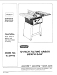
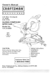
Owner's Manuam
2/3 HP (Maximum
400-3000 RPM
518 Inch Chuck
Developed)
33oWNCHVARIABLE
SPEED
LL PRESS
CAUTmONo`
o
o
o
,,
o
,,
Before using this Drill Press,
read this manual and follow
all its Safety Rules and
Operating Instructions.
@ustemer
Safety Instructions
Ynstallation
Operation
Maintenance
Parts List
Espa_ol
He_lp L_ne
1-8ee.843.1682
Sears, Roebuck
and COo, Hoffman
Part No, 137229130002
Estates,
mL60179 USA
SECTION
PAGE
Warranty ...................................................................
Product Specifications
......................................................
Safety _nstructions
..........................................................
Accessories
and Attachments
................................................
Carton Contents
...........................................................
Know Your Driti Press
.......................................................
Glossary
of Terms
...........................................................
AssemMy
and Adjustments
.................................................
Operation
................................................................
Maintenance
..............................................................
Troubleshooting
guide ......................................................
Parts ....................................................................
EspaSol
.................................................................
2
2
3
6
6
8
9
10
!3
18
19
20
29
GENERAL SAFETY INSTRUCTIONS
BEFORE
To avoid mistakes that could cause serious injury, do not
plug the drill press in until you have read and understood
the following:
°
.
.
Contact a Sears Service Center for repair.
MAKE WORKSHOP KID PROOF with padlocks, master
switches, or by removing starter keys.
.
DON'T FORCE THE TOOL. It will do the job better
and safer at the rate for which it was designed.
9.
CHUCK SIZE .............
5/8"
SPEEDS .................
400 - 3000 RPM
MOTOR
120V, 60 HZ, 5.gAMPS
.................
HORSEPOWER
...........
2/3 HP (Max. Developed)
BUiLT-IN UGHT ...........
........................
TABLE SiZE ..............
60 Watt (Maximum)
(Bulb not included)
I3-1/4" x 13-1/4"
TABLE TILT
45 ° RIGHT OR LEFT
..............
SPINDLE TRAVEL
.........
SPINDLE TO COLUMN
3-t/4"
.....
BASE SiZE ...............
ACCESSORY
HEIGHT
iNCLUDED
.................
To avoid electrical hazards, fire hazards, or damage to
the tool, use proper circuit protection.
Your drill p[ess is wired at the factory for 120V operation.
Connect to a 120V, 15 AMP branch circuit and use a 15
AMP time delay fuse or circuit breaker. To avoid shock or
fire, replace power cord immediately if it is worn, cut or
damaged in any way.
t5.
17. USE RECOMMENDED ACCESSORIES. Consult the
owner's manual for the recommended accessories.
The use of improper accessories may cause risk of
injury to persons.
18. NEVER STAND ONTOOL Serious injury could occur
if the tool is tipped or if the cutting tool is unintentionally
contacted.
19. CHECK FOR DAMAGED PARTS. Before further use of
the toot, a guard or other part that is damaged should
be carefully checked to determine that it will operate
properly and perform its intended function. Check for
alignment of moving parts, binding of moving parts,
breakage of parts, mounting, and any other conditions
that may affect its operation. A guard or other part that
is damaged should be properly repaired or replaced.
USE THE RIGHT TOOL. Don't force tool or the
attachment to do a job for which it was not designed.
10. USE PROPER EXTENSION CORD. Make sure your
extension cord is in good condition. When using an
extension cord, be sure to use one heavy enough to
carry the current your product will draw. An undersized
cord will cause a drop in line voltage resulting in loss
of power and overheating. The table on page 5 shows
the correct size to use depending on cord length and
nameplate ampere rating. If in doubt, use the next
heavier gauge. The smaller the gauge number, the
heavier the cord.
20. NEVER LEAVE TOOL RUNNING UNATTENDED.
TURN THE POWER OFF. Don't leave the tool until
it comes to a complete stop.
21. DON'T OVERREACH.
balance at all times.
11. WEAR PROPER APPAREL. DO NOT wear loose
clothing, gloves, neckties, rings, bracelets, or other
jewelry which may get caught in moving parts.
Nonslip footwear is recommended. Wear protective
hair covering to contain long hair.
23. DBRECTION OF FEED. Feed work into a blade or cutter
against the direction of rotation of the blade or cutter
only.
6-1/2"
FENCE
66-1/32"
Keep proper footing and
22. MAINTAIN TOOLS WITH CARE. Keep tools sharp
and clean for best and safest performance. Follow
instructions for lubricating and changing accessories.
18-15/64" x 10-13/I6"
....
DISCONNECT TOOLS before servicing, and when
changing accessories, such as blades, bits, cutters,
and the like.
t6. REDUCE THE RISK OF UNiNTENTiONAL STARTING.
Make sure the switch is in OFF position before
plugging in.
DON'T USE IN A DANGEROUS ENVIRONMENT.
Don't use power tools in damp or wet locations, or
expose them to rain. Keep work area well lighted.
.
This warranty gives you specific legal rights, and you may also have other rights which vary from state to state.
ALWAYS WEAR EYE
PROTECTION. Any drill press
can throw foreign objects into
the eyes which could cause
permanent eye damage.
ALWAYS 'wear Safety Goggles
(not glasses) that comply with
ANSI safety standard Z87.1. Everyday eyeglasses
have only impacFresistant lenses. They ARE NOT
safety glasses. Safety Goggles are available at Sears.
NOTE: Glasses or goggles not in compliance with ANSt
Z87.1 could seriously hurt you when they break.
14. SECURE WORK. Use clamps or a vise to hold work
when practical. It's safer than using your hand and it
frees both hands to operate tool.
KEEP WORK AREA CLEAN. Cluttered areas and
benches invite accidents.
KEEP CHILDREN AWAY. All visitors should be kept at
a safe distance from the work area.
WEARVOUR
l& WEAR A FACE MASK OR DUST MASK.
Drilling operation produces dust.
REMOVE ADJUSTING KEYS AND WRENCHES.
Form the habit of checking to see that keys and
adjusting wrenches are removed from the tool before
turning ON.
.
If this product is used for commercial or rental purposes, this warranty applies only for 90 days from the date of
purchase.
Estates, IL 60179
READ and become familiar with this entire instruction
manual. LEARN the tool's applications, limitations, and
possible hazards.
KEEP GUARDS IN PLACE and in working order.
2.
FULL ONE YEAR WARRANTY
Sears, Roebuck and Co., Dept. 817 WA, Hoffman
THE DRNLL PRESS
Safety is a combination of common sense, staying alert
and knowing how to use your dri!t press.
3.
If this product fails due to a defect in material or workmanship within one year from the date of purchase, Sears
witl repair it free of charge.
USING
12.
SAVE THESE INSTRUCTIONS
3
24.WARNING:
Dustgenerated
fromcertainmaterials
canbe
injurioustoyourhealth.Alwaysoperatedrillpressin wel!
ventilatedareasandprovideforproperdustremoval.
SPECJFRC SAFETY NSTRUCT ONS
FOR THE DRILL PRESS
2.
3.
THIS DRILL PRESS is intended for use in dry
conditions, indoor use only.
WEAR EYE PROTECTION. USE face or dust mask
along with safety goggles if drilling operation is dusty.
USE ear protectors, especially during extended periods
of operation.
DO NOT wear gloves, neckties, or loose clothing.
5.
DO NOT try to drill material too small to be securely
held.
6.
7.
9.
WHEN cutting a large piece of material make sure it
is fully supported at the table height.
iN THE EVENT OF A MALFUNCTION OR BREAKDOWN,
grounding provides a path of least resistance for electric
current and reduces the risk of electric shock. This tool is
equipped with an electric cord that has an equipment
grounding conductor and a grounding plug. The plug MUST
be plugged into a matching recep[acle that is properly
installed and grounded in accordance with ALL local codes
and ordinances.
NEVER turn your drill press on before clearing the
table of all objects (tools, scraps of wood, etc.)
20. LETTHE SPINDLE REACH FULL SPEED before
starting to drill, tf your drill press makes an unfamiliar
noise or if it vibrates excessively, stop immediately,
turn the drill press off and unplug. Do not restart until
the problem is corrected.
iMPROPER CONNECTION of the equipment grounding
conductor can result in risk of electric shock. The conductor
with the green insulation (with or without yellow stripes) is
the equipment grounding conductor, tf repair or replacement
of the electric cord or plug is necessary, DO NOT connect
the equipment grounding conductor to a live terminal.
25. TO AVOID INJURY from accidental starting, always
turn the switch OFF and unplug the drill press before
installing or removing any accessory or attachment
or making any adjustment.
26, KEEP GUARDS IN PLACE and in working order.
27, USE ONLY SELF-EJECTmNG TYPE CHUCK KEY as
provided with the drill press,
ELECTRMCAL REQUIREMENTS
POWER SUPPLY AND MOTOR SPEC_FRCATJONS
12. CLAMP WORKPIECE OR BRACE against the left
side of the column to prevent rotation, if it is too short
or the table is tilted, clamp solidly to the table and
use the fence provided.
To avoid electrical hazards, fire hazards, or damage to the
tool, use proper circuit protection, Use a separate electrical
circuit for your tools.Your drill press is wired at the factory
for 120V operation. Connect to a t20V, 15 Amp circuit and
use a 15 Amp time delay fuse or circuit breaker. To avoid
shock or fire, if power cord is worn or cut, or damaged in
any way, have it replaced immediately.
13. JFTHE WORKPIECE overhangs the table such that
it will fall or tip if not held, clamp it to the table or
provide auxiliary support.
INSTRUCTIONS
4
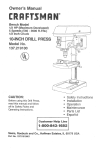
Fig, A
3-Prong
DO NOT MODIFY THE PLUG PROVIDED. If it will not fit
the receptacle, have the proper receptacle ins[ailed by a
qualified electrician.
24. [JIAKE SURE the spindle has come to a complete
stop before touching the workpiece.
1t. MAKE SURE there are no nails or foreign objects in
the part of the workpiece to be drilled.
_NSTRUCT_ONS
19. BEFORE STARTING the operation, jog the motor
switch to make sure the drill bit does not wobble or
vibrate.
23. WHEN DRILUNG large diameter holes, clamp the
workpiece firmly to the table. Otherwise, the bit may
grab and spin the workpiece at high speed. DO NOT
USE fly cutters or multiple-part hole cutters, as they
can come apart or become unbalanced in use.
I0. DO NOT perform any operation freehand. ALWAYS
hold the workpiece firmly against the table so it will
not rock or twist. Use clamps or a vise for unstable
workpieces.
SAVE THESE
16. MAKE SURE all clamps and locks are firmly
tightened before drilling.
22. USE RECOMMENDED SPEED for drill accessory and
workpiece material. SEE INSTRUCTIONS that come
with the accessory.
DO NOT install or use any drill bit that exceeds
175 mm (7") in length or extends 150 mm (6") below
the chuck jaws. They can suddenly bend outward or
break.
DO NOT USE wire wheels, router bits_ shaper cutters,
circle (fly) cutters, or rotary planers on this drill press.
This tool must be grounded while in use to protect the
operator from electrical shock.
21. DO NOT perform layout assembly or set up work on
the table while the drill press is in operation.
ALWAYS keep hands out of the path of a drill bit.
Avoid awkward hand positions where a sudden slip
could cause your hand to move into the drill bit.
8.
15. WHEN using a drill press vise, always fasten to the
table.
t8.
YOUR DRILL PRESS MUST BE BOLTED securely
to a workbench. In addition, if there is any tendency
for your drill press to move during cer[ain operations,
bolt the workbench to the floor.
4.
GROUNDING
I7. SECURELY LOCKTHE HEAD and table support to
the column, and the table to the table support before
operating the drill press.
For your own safety, do not try to use your drill press
or plug it in until it is completely assembled and installed
according to the instructions, and until you have Yeadand
understood this instruction manual.
,
i4. SECURE WORK. Use clamps or a vise to hold the
work when practical. It's safer than using your hand
and it frees both hands to operate t0ol.
Grounding
Use a separate electrical circuit for your tools. This circuit
must not be less than #12 wire and should be protected
with a 15 Amp time lag fuse. Before connecting the motor
to the power line, make sure the switch is in the OFF position
and the electric current is rated the same as the current
stamped on the motor nameplate. Running at a lower voltage
will damage the motor.
This tool is intended for use on a circuit that has a receptacle
like the one illustrated in FIGURE A. FIGURE A shows a
3-prong electrical plug and receptacle that has a grounding
conductor, tf a properly grounded receptacle is not available,
an adapter (RGURE B) can be used to temporarily connect
this plug to a 2-contact ungrounded receptacle. The adapter
(FIGURE B) has a rigid lug extending from it that MUST be
connected to a permanent earth ground, such as a properly
grounded receptacle box. THE TEMPORARY ADAPTER
SHOULD BE USED ONLY UNTIL A PROPERLY
GROUNDED OUTLET CAN BE INSTALLED BY A
QUAUFIED ELECTRiCiAN, The Canadian Electrical Code
prohibits the use of adapters.
CAUTION: In all cases, make certain the receptacle is
properly grounded. If you are not sure have a qualified
electrician check the receptacle.
SAVE THESE
Prong
Properly Grounded
3-Prong Receptacle
Fig. B
Grounding
Lug
Q"s_`
,f
Make Sure This
is Connected to a
Known Ground
°
z _<:<_ik_
CHECK with a qualified electrician or service person if you
do not completely understand the grounding inslructions, or if
you are not sure the tool is properly grounded.
USE ONLY 3-wire extension cords that have 3-prong
grounding plugs and 3-pole receptacles that accept
the tool's plug. Repair or replace damaged or worn
cord immediately.
Plug
2-Prong
7
Receptacle
Adapter
This drill press is for indoor use only. Do not expose to rain
or use in damp locations
GU_DEUNES
FOR
EXTENSION
CORDS
USE PROPER EXTENSION CORD. Make sure your
extension cord is in good condition. When using an extension
cord, be sure to use one heavy enough to carry the current
your product will draw. An undersized cord will result in a
drop in line voltage and in toss of power which will cause the
tool to overheat. The table below shows the correct size to
use depending on cord length and nameplate ampere rating.
If in doubt, use the next heavier gauge. The smaller the
gauge number, the heavier the cord.
Be sure your extension cord is proper_y wired and in
good condition. Always replace a damaged extension cord or
have it repaired by a qualified person before using it. Protect
your extension cords from sharp objects, excessive heat and
damp or wet areas.
(when
A__rapere
mo_'e
lhan
Rating
not
using
Total
more
than
120 volts
length
onJy)
of cord
i,n, f, eet
1 O0'
150'
25'
50'
0
6
18
16
16
14
6
10
18
16
14
12
!0
12
16
16
14
12
16
14
12
Not
NSTRUCTJONS
12
Recommended
UNPACKING YOUR DR LL PRESS
AVAILABLE
ACCESSORnES
Visit your Sears Hardware Department or see the Sears
Power and Hand Tools Catalog for the following accessories:
o
o
•
-
Drill bits
Hold-Down and Guide
Drill Press Vises
Clamping Kit
To avoid personal injury:
o
Use only accessories recommended for this drill press.
o
Follow instructions that accompany accessories. Use
of improper accessories may cause hazards.
o
Use only accessories designed for this drill press to
avoid injury from thrown broken parts or workpieces.
Do not use any accessory unless you have completely
read the instruction or owner's manual for that
accessor_
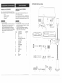
UNPACKING
CONTENTS
AND CHECKING
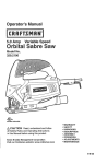
Carefully unpack the drill press and all its parts, and
compare against the list below.
To protect the drill press from moisture, a protective coating
has been applied to the machined surfaces. Remove this
coating with a soft cloth moistened with kerosene or WD-40.
To avoid personal injury:
•
If any part is missing or damaged, do not plug the drill
press in until the missing or damaged part is replaced,
and assembly is complete.
•
To avoid fire or toxic reaction, never use gasoline,
naphtha, acetone, lacquer thinner or similar highly
volatile solvents to clean the drill press.
ITEM
DESCRIPTION
A.
B.
C,
D,
E,
Head assembly
Table
Base
Column assembly
Speed control knob and collar
I
1
1
1
1
R
G.
H,
I,
J.
K.
L.
M.
N.
O.
Loose parts bag:
Lock handle
Crank handle
Hex bolts
Fence assembly
Triangle knobs
T-Block
Washer
Hex wrenches
Wedge
Arbor
1
1
4
1
2
2
2
2
1
1
R
Q.
Box:
Chuck key
Chuck
1
1
A
QUANTITY
C
F
G
J
M
N
0
K
P
Q
D
Speed control knob
Speed chart
Belt guard cover
Fence end_
Fence backstop
Upper stop nut
Lower stop nut
Depth scale
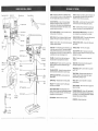
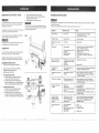
BASE - Supports the drill press. For additional stability,
holes are provided in the base to bolt the drill press to the
floor. (See "Specific Safety Instructions for Drill Presses".)
FENCE -Attaches to the table to align the workpiece or for
fast repetitive drilling. Removable. Remove fence when it
interferes with other drill press accessories.
BACKUP MATERIAL -A piece of scrap wood placed
between the workpiece and table. The backup board
prevents wood in the workpiece from splintering when the
drill passes through the backside of the workpiece. It also
prevents drilling into the table top.
HEAD LOCKS - Locks the head to the column, ALWAYS
lock the head in place while operating the drill press.
BELT GUARD ASSEMBLY -Covers
during operation of the drill press.
REVOLUTION PER M_NUTE (R.P.M.) - The number of
turns completed by a spinning object in one minute.
the pulleys and belt
RACK -Combines with gear mechanism to provide easy
elevation of the table by the hand operated table crank.
BEVEL SCALE - Shows the degree of table tilt for bevel
operations. The scale is mounted on the side of the arm.
SPEED CONTROL CHART - Choose the drilling speed by
moving the knob lever's location on the chart.
CHUCK - Holds the drill bit or other recommended accessory
to perform desired operations.
SPEED CONTROL KNOB - Changes the drilling speed
when moved.
CHUCK KEY -A self-ejecting chuck key which will pop out
of the chuck when you let go of it. This action is designed
to help prevent throwing of the chuck key from the chuck
when the power is turned ON. Do not use any other key as
a substitute; order a new one if damaged or lost.
SPINDLE SPEED -The
COLUMN - Connects the head, table, and base on a
one-piece tube for easy alignment and movement,
TABLE - Provides a working surface to support the
workpiece,
COLUMN COLLAR - Holds the rack to the column. Rack
remains movable in the collar to permit table support
movements.
TABLE ARM - Extends beyond the table support for
mounting and aligning the table.
Depth stop
Motor
Stop nut
Power
cord
Chuck key
storage
Light switch
ON/OFF switch
Head locking
set screws
Chuck
Table
support lock
Feed
handles
Column
collar
Column
Rack
Table arm
Bevel
scale
Table
Table
support
Table lock
Table bevel lock
Table
crank
COLUMN SUPPORT -Supports the column, guides the
rack and provides mounting holes for column to base,
DEPTH SCALE STOP NUTS - Lock the spindle to the
selected depth.
DEPTH SCALE - Indicates depth of hole being drilled.
DRILL BIT -The cutting tool used in the drill press to
make holes in a workpiece.
5/8" Threaded drain
Spindle
Quill
DRILL ON/OFF SWITCH - Has locking feature, This
feature is intended to help prevent unauthorized and possible
hazardous use by children and others. Insert the key into
the switch to turn the drill press on.
Column support
0° Locking
TABLE SUPPORT LOCK -Tightening locks the table
support to the column. Always have it locked in place while
operating the drill press.
TABLE BEVEL LOCK - Locks the table in any position
from 0 °- 45 °.
TABLE CRANK - Elevates and lowers the table. Turn
clockwise to elevate the table. Support lock must be
released before operating the crank.
TABLE LOCK - Locks the table after it is rotated to
various positions.
TABLE SUPPORT - Rides on the column to support the
table arm and table.
THREADED DRAIN (5/8") -Attach a 5/8" (pipe threaded)
metal pipe to the threaded opening for draining excess oil
into container. For a non-draining surface attach a threaded
metal plug. Pipe and plug not included,
FEED HANDLE - Moves the chuck up or down.
set screw
WORKPIECE
'" Arbor
_
Chuck
Chuck key
R.RM. of the spindle.
Base
-Material
being drilled.
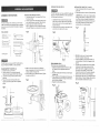
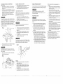
INSTALLING THE HEAD (FIG. D)
INSTALLING THE CHUCK {FIG. F, G, and H)
1. Clean out the tapered hole in the chuck (1) with a
clean cloth.
The Drill Press head is very heavy and MUST be lifted with
the help of 2 PEOPLE OR MORE, to safely assemble the
Drill Press head on the column.
2.
I
ASSEMBLY
NSTRUCTJONS
For your own safety, never connect plug to power source
outlet until all assembly and adjustment steps are completed,
and you have read and understood the safety and operating
instructions.
iNSTALLING THE TABLE (F_G. B and C)
1. Locate the table crank (1) and support tock (2) from
the loose parts bag.
2. Insert the support lock handle into the hole (3) at the
rear of the table support assembly. Tighten by hand,
3. Install the table crank handle onto the small
shaft (4), aligning the set screw (5) with the flat surface
of the shaft. Tighten the set screw with a hex wrench.
1.
2.
Fig, B
TOOLS NEEDED
Clean tapered surfaces on the arbor (2) and spindle (3).
CAUTION: Make sure there are no foreign particles
sticking to the surfaces. The slightest piece of dirt on
any of these surfaces will prevent the chuck from
seating properly. This will cause the drill chuck and
bit to wobble. If tapered hole inside spindle is
extremely dirty, use a cleaning solvent.
Carefully lift the head (t) above the column (2) and
slide it onto the column. Make sure the head slides
down over the column as far as possible. Align the
head with the base.
Using [he hex wrench, tighten the two head lock set
screws (3) on the right side of the head.
Fig. F
Fig. D
Slotted screwdriver
3
8" & t0" Adjustable wrenches
2
--ta 0
Combination wrench
[ ! L L! ! r_-!_
Framing Square
Combination
fl
square
_--_"
Socket wrench with
23 mm. socket
3
2
3.
4.
The Drill Press is very heavy and MUST be lifted with the
help of 2 PEOPLE OR MORE, to safely assemble it.
COLUMN SUPPORTTO BASE (FIG. A)
1. Position the base (1) on the floor.
2. Place the column (2) on the base, aligning the
holes in the column support with the holes in the base.
3. Locate the four long hex bolts (3) from the ]oose
parts bag.
4. Place aboft in each hole through the column
support and the base. Tighten with an adjustable
wrench.
4.
5.
(FIG. C) Loosen the support lock (2). Raise the
table arm assembly by turning the crank handle (1)
clockwise. Tighten the support lock.
Place the table (6) in the table arm assembly, Tighten
the table lock handle (7).
FENCE ASSEMBLY (F_G. E)
This drill press has a channeled tabfe top.
1. Determine the desired location for the fence (1). Slide
the T-blocks (2) into the appropriate channels as
shown.
2. Align the mounting holes of the fence over the T-block's
threaded holes.
3.
Fig, C
4.
Place a washer (3) on the threaded end of the knob (4).
Insert the knob through the mounting hole of the fence
into the T-block, and tighten,
Repeat for the other knob and T-block.
Fig. E
Fig, A
4
5.
6.
(FIG. G) Push the chuck (1) onto the spindle
arbor (2), Tap gently to ensure seat.
Lower the spindle by turning the feed handles (3)
counterclockwise, until the slot (4) appears on the
quill (5).
Push the chuck and spindle arbor up into the spindle,
making sure the tang (upper narrow end of the
spindle arbor shank) is engaged and locked in the
inner slot (6) of the spindle. This can be seen
through the outer slot (4) of the quill by rotating the
chuck and arbor until the two slots are aligned.
Open the jaws of the chuck (1) by rotating the chuck
sleeve clockwise. To prevent damage, make sure the
jaws are completely receded into the chuck.
Fig. G
7.
Using a rubber mallet, ptasticqipped hammer, or a
block of wood and a hammer, firmly tap the chuck
upward into position on the spindle shaft. (FIG. H)
DRNLL PRESS
BEVEL SCALE (FIG. L and tgl)
ADJUSTMENTS
NOTE: The bevel scale has been included to measure
approximate bevel angles. If precision is necessary,
a square or other measuring tool should be used to position
the table. To use the bevel scale (7):
1. Loosen the locking set screw (4) to RELEASE it from
the table supporL
2. Loosen the large hex head bevel locking bolt (6).
CAUTION: Allthe adjustments for the operation of the
drill press have been completed at the factory, Due to normat
wear and use, some occasional readjustments may be
necessary.
Fig. H
To prevent personal injury, always disconnect the plug from the
power source when rnaking any adjustments.
SQUARING
fl<--
!.
Insert the speed control knob (1) into the head assembly and
tighten.
(FtGo K and L)
2.
3.
NOTE: When installing the knob (1), be sure the red
Insert a 1/4', or larger diameter, precision ground
steel rod (t), approximately 3" long, into the chuck (2).
Tighten the chuck jaws.
Raise table to working height and lock.
Using the combination square (3), place one edge
flat on the table, and align the other edge vertically
beside the rod (1).
When the indicator on the control knob (1) is in line
with the desired speed on the speed scale, turn the
speed control knob clockwise unLil tight to Jock.
Fig. N
To prevent injury, be sure to hold the table & table arm
assembly, so it will not swivel or tilt.
3.
NOTE: The table arm and support has a predrilled hole
with a locking set screw inserted for locking the table to
a predetermined 0 ° horizontal position. It must be loosened to
change the angle of the table.
INSTALLING THE SPEED CONTROL KNOB (F_G. t)
1.
"TABLE TO HEAD
3,
4.
5.
6.
Tilt the table, aligning the desired angle measurement
to the zero line opposite the scale (7).
Tighten the bevel locking bolt (6).
To return the table to its original position, loosen the
bevel locking bolt (6). Realign the bevel scale (7) to
the 0° position.
Tighten the locking set screw (4) until it is seated in
the horizontal 0 ° hole of the table support.
%)
2008
1800
400
,500
Fig. M
I
1500
!
800
808
lines on the lever stay upwards.
F_g,, K
2-
Fig.
.
0
E -
DR_LUNG
SPEED
TABLE
(rprn)
5
Drill Bit
Diam.
(Inches)
6
7
4
Material
Wood
Aluminum
1/16
(
3000
3/32
Maximum
2000
1/8
3000
1500
3/16
2000
800
4.
INSTALLING LIGHT BULB (F_G.J) (not included)
1. Install a light bulb (no Iarger than 60 watt) into the
socket inside the head.
If an adjustment is necessary, loosen the locking set
screw (4) with the 3 mm hex key to RELEASE the
table from the horizontal position.
5. Loosen the large hex head bevel locking bolt (6).
Steel
To prevent injury, be sure to hold the table & table arm
assembly, so it will not swivel or tilt.
Fig. d
6.
7.
t
Align the square to the rod by rotating the table until
the square and rod are in line.
Retighten the large hex bolt (6).
Fig. L
BASIC DRILL PRESS OPERATIONS
7/32
To prevent personal injury, always disconnect plug from the
power source when making any adjustments.
1/4
3000
5/16
2000
CHANGING THE DRiLLiNG SPEED (FIG. N)
This drill press has a speed range from 400 to 3000 RPM.
3/8
Choose the proper speed for the drilling operation and the
type cutter or drill bit being used.
!/2
1500
9/16
800
NOTE: Adjust the drilling speed only when the drill press is
switched ON and the chuck spindle is running. Be sure to
follow the steps below to make the speed adjustment.
5
Maximum
I.
With the tool running unlock the speed control knob (1)
on the left of the drill press head assembly by turning
counterclockwise.
2.
Move the lever to the front to decrease the speed and
to the rear to increase the speed.
6
i_i!i_i_i
!i:_::!_!:;:_::!:i_i?::i::,_i:::!i;i:!:LZ::
L;::
i_::::?i_/:
:::i
il//:_:i:IZ;::?::L:::///!_:/(:
¸i:IZ_I_
;:i::::i
i¸I::i_:_IZ:I:
i::i!/:
"I:II,!:
i_:::,i::/::::_::
%i;:!:!L12 :i_:_::i_
i':_::;:::
(:,:::::
:!i:i:_<:_//:_!::
_;L:::
:?/_:!:ii:
:¸
:::::(:i_i
::::i:::_i::::':::_i
i:i):i_i
:i_:,:_ili;
i_!:!i::!_':_!!;
!::i
!ii:!!ili:i!;:!i:_ii!!i:i;:!ii_iii:i:
!!i:i:!:!iii_,!iiii_!ii:!ii!i%!_ii::i:ili!i_i!;!:i:i!;:!:_iiii_:i:ii_:
600
800
400
5/8
600
4O0
25/32
13
1500
1-1/8
600
1-1/4
40O
ON/
OFF SWITCH PANEL (FIG. O)
The ON / OFF switch has a removable, yellow plastic key,
With the key removed from the switch, unauthorized and
hazardous use by children and others is minimized.
1. To turn the drill press ON, insert key (1) into the slot of
the switch (2), and move the switch upward to the ON
position.
2. To turn the drill press OFF, move the switch downward.
3. To lock the switch in the OFF position, grasp the end,
or yellow part, of the switch toggle, and putt it out.
4. With the switch key removed, the switch will not operate.
5. If the switch key is removed while the drill press is
running, it can be turned OFF but cannot be restarted
without inserting the switch key.
6. To turn the worklight ON, press the rocker switch (3).
7. Never leave the drill press unattended. Turn the light
switch and power switch OFF and wait until it comes
to a complete stop.
Fig. O
MAX
LAMP
60 W
AMgOULE
60W
DRILLING TO A SPECIFIC DEPTH (FIG. R)
Drilling a blind hole (not all the way through workpiece)
to a given depth can be done two ways:
Fig. P
Workpiece
2
1.
2.
3.
4.
5.
To prevent the workpiece or backup material from being torn
from your hands while drilling, you MUST position the
workpiece against the LEFT side of the column, tf the
workpiece or the backup material is not tong enough to reach
the column, damp it to the table, or use the fence provided with
the drill press to brace the workpiece. Failure to secure the
workpiece could result in personal injury.
6.
LUM|ERE
OFF
1
ALWAYS lock the switch OFF when the drill press is not in use.
Remove the key and keep it in a safe place. In the event of a
power failure, blown fuse, or tripped circuit breaker, turn the
switch OFF and remove the key, preventing an accidental
startup when the power comes on.
INSTALLING DRILL BIT IN CHUCK (FIG. P)
1. With the switch OFF and the yellow switch key
removed, open the chuck jaws (1) using the chuck
key (2). Turn the chuck key counterclockwise to open
the chuck jaws (1).
2. Insert the drill bit (3) into the chuck far enough to obtain
maximum gripping by the jaws, but not far enough to
touch the spiral grooves (flutes) of the drill bit when the
jaws are tightened.
3. Make sure that the drill is centered in the chuck,
4. Turn the chuck key clockwise to tighten the jaws.
method
Mark the depth (1) of the hole on the side of the
workpiece.
With the switch OFF, bring the drill bit down until the
tip is even with the mark.
Hold the feed handle (2) at this position.
Spin the lower nut (3) down to contact the depth stop (4)
on the head.
Spin the upper nut (5) down and Iighten against the
lower nut (3).
The drill bit will now stop after traveling the distance
marked on the workpiece.
Fig.
s
3
NOTE: With the chuck up the tip of the drill bit must be
slightly above the top of the workpiece.
t.
2.
3.
4.
jLISt
2
With the switch OFF, turn the feed handle (2) until the
depth stop (4) points to the desired depth on the depth
scale (6) and hold the feed handle in that position.
Spin the lower nut (3) down to contact the depth
stop (4).
Spin the upper nut (5) against the lower nut (3) and
tighten.
The drill bit will stop after traveling the distance selected
on the depth scale.
1
REMOVING CHUCK AND ARBOR (FIG. T)
!. With the switch OFF:,adjust the depth stop nut (1) to
hold the drill at a depth of three inches. (See instructions
for "LOCKING CHUCK AT DESIRED DEPTH").
2. Align the key holes in the spindle (2) and quill (3) by
rotating the chuck by hand.
3. Insert the key wedge (4) into the key holes (2 & 3).
4. Tap the key wedge (4) lightfy with a plastic tipped
hammer, until the chuck and arbor fall out of the
spindle.
NOTE: Place one hand below the chuck to catch it
when it falls out.
Fig. Q
1
\
3
-_
Depth scale method
MAX
USING THE FENCE (FIG. Q)
The fence provides a way of accurately and quickly setting
up the workpiece for more precision or for repetitive drilling
operations.
1. Using the centerpunch or sharp nail, make an
indentation in the workpiece where you want to drill.
2. Lower the drill bit to align with the indentation on the
workpiece. See "HOLDING A DRILLING LOCATION"
page 16.
3. Loosen the knobs (1) and slide the fence back stop (2)
firmly against the long side of the workpiece. Tighten
the knobs when in position.
4. Loosen the wing nut (3) and slide the end stop (4) along
the fence until it is firmly against the left side of the
workpiece. Tighten the wing nut.
5. Check the accuracy by drilling a scrap workpiece.
Adjust if needed.
6. Hold with your hand or clamp the top surface of the
workpiece firmly to prevent it from lifting off the table
when the bit is raised.
LOCKING THE CHUCK AT THE DESIRED DEPTH
(FIG. S)
1. With the switch OFF, turn the feed handles until the
chuck (1) is at the desired depth. Hold the feed handles
at this position.
2. Turn the stop nut (2), Iocated underthe depth stop (3),
counterclockwise and upwards untit it is against the
depth stop.
3. The chuck wilt now be held at this position when the
feed handles are released.
4
To avoid injury or accident by the chuck key ejecting
forcibly from the chuck when the power is turned ON, use
only the self-ejecting chuck key supplied with this drill press.
ALWAYS recheck and remove the chuck key before turning
the power ON.
15
HOLDING A DRILLING LOCATION
1. Using a centerpunch or sharp nail, make an indentation
in the workpiece where you want the hole.
2. Using the feed handles, bring the drill down to align
with the indentation before turning the drill ON.
POSmTtONING THE TABLE AND WORKPIECE
(FIG. U, and V)
1. Lock the table (!) to the column (2) at a position so
the tip of the drill bit (3) is just above the top of the
workpiece (4).
2. ALWAYS place a BACK-UP MATERIAL (scrap wood)
on the table beneath the workpiece. This will prevent
splintering or heavy burring on the underside of the
werkpiece. To keep the back-up material from
spinning out of control, it MUST contact the LEFT
side of the column.
TILTING THE TABLE (FIG. W)
NOTE: The table arm and support (1) has a predrilled hole
with a locking set screw inserted for locking the table into a
predetermined 0° horizontal position.
1.
To prevent the workpiece or backup material from being
torn from your hands while drilling, you MUST position it
against the LEFT side of the column. If the workpiece or the
backup material is not long enough to reach the column,
use the fence provided with the drill press to brace the
workpiece, or clamp it to the table. Failure to do this could
result in personal injury.
2.
To use the table in a bevel (tilted) position, turn the
locking set screw (2) with the hex key counterclockwise
to release it from the table support.
Loosen the large hex head bevel locking bolt (3).
BASIC OPERATION
J
For your own safety, always observe the SAFETY
INSTRUCTIONS listed here and on pages 3, 4, and 5
of this Owner's Manual.
YOUR PROTECTION
To avoid being pulled into the power tool, do not wear
loose clothing, gloves, neckties, or jewelry. Always tie back
long hair.
,
To prevent injury, be sure to hold the table & table arm
assembly, so it will not swivel or tilt.
3.
-2
4.
5.
Tilt the table, aligning the desired angle measurement
to the zero line opposite the scale (4). Tighten the bevel
locking bolt.
To return the table to its original position, loosen the
bevel locking bolt (3). Realign the bevel scale (4) to
the 0 ° position.
Using the hex key, turn the locking set screw (2)
clockwise to seat into the hole.
To avoid injury from spinning work or tool breakage, always
clamp workpiece and backup material securely to the table
before operating the drill press with the table tilted.
3.
c.
To get the best results and minimize the likelihood of personal
injury, follow these instructions for operating your drill press.
,
Fig. U
SAFETY
.
If any part of your drill press is missing, malfunctioning,
damaged or broken, stop operation immediately until
that part is properly repaired or replaced.
Never place your fingers in a position where they
could contact the drill bit or other cutting tool. The
workpiece may unexpectedly shift, or your hand
could slip.
To prevent the workpiece from being torn from your
hands, thrown, spun by the tool, or shattered, always
properly support your workpiece as follows:
a. Always position BACKUP MATERIAL (used
beneath workpiece) so that it contacts the left
side of the column, or use the fence provided and
a clamp to brace a smaller workpiece.
b. Whenever possible, position the WORKPtECE to
contact the left side of the column. If it is too short
or the table is tilted, use the fence provided or
clamp solidly to the table, using the table slots.
4.
5.
6.
For smalt pieces that cannot be clamped to the table,
use a drill press vise (optional accessory).
The drill press vise MUST be clamped or bolted to the
table to avoid injury from a spinning workpiece, or damaged
vise or bit parts.
4.
Remove the drill press fence when it interferes with
other drill press accessories.
3
2
FEEDING
1. Pull down the feed handles with only enough effort to
allow the drill bit to cut.
2. Feeding too slowly might cause the drill bit to burn.
Feeding too rapidly might stop the motor, cause the
belt or drill to slip, or tear the workpiece loose and
break the drill bit.
3. When drilling metal, it may be necessary to lubricate
the drill bit tip with motor oil, to prevent burning the tip.
16
17
When using a drill press vise, always fasten it to
the table.
d. Never do any work freehand (hand-holding the
workpiece rather than supporting it on the table),
except when polishing.
e. Securely lock the head and support to the
column, the table arm to the support, and the table
to the table arm, before operating the drill press.
f. Never move the head or the table while the tool
is running.
g. Before starting an operation, jog the motor switch
to make sure the drill or other cutting tool does
not wobble or cause vibration.
h. If a workpiece overhangs the table so it wit! fall
or tip if not held, clamp it to the table or provide
auxiliary support.
i.
Use fixtures for unusual operations to adequately
hold, guide, and position workpiece.
j.
Use the SPINDLE SPEED recommended for the
specific operation and workpiece material. Check
the panel on the inside pulley cover or the chart
below for drilling speed information. For accessories,
refer to the instructions provided with each
accessory.
Never climb on the drill press table, it could break or
pull the entire drill press down on you.
Turn the motor switch OFF, and put away the
switch key when leaving the drill press.
To avoid injury from thrown work or tool contact, do
not perform layout, assembly, or set up work on the
table while the cutting tool is rotating.
MAINTAiNiNG
YOUR DR LL PRESS
6.
7.
8.
For your own safety, turn the switch OFF and remove the
plug from the power source outlet before maintaining or
lubricating your drill press.
Frequently blow out, using an air compressor or dust vacuum,
any dust that accumulates inside the motor.
A coat of automotive paste wax applied to the table and
column will help to keep the surfaces clean.
Remove the speed control knob and collar.
Replace the pulley cover on the head assembly and
tighten the pulley cover screws.
Install the speed control knob and collar.
To avoid injury, be sure to remove the plug from the power
source outlet and wait for the pulleys to come to a complete
stop before changing the belts.
TROUBLESHOOTnNG
GUDE
To avoid injury from an accidental start, turn the switch OFF and always remove the plug from the power source before
making any adjustments.
,, Consult your local Sears Service Center if for any reason the motor wilt not run.
PROBLEM
PROBABLE
CAUSE
Noisy operation.
1, Dry spindle.
Insufficient torque,
t.
REMEDY
1. Lubricate the spindle. See "Lubrication"
in MAINTENANCE Section,
Fig, X
Speed too high.
1. Reduce the speed,
...............................
To avoid shock or fire hazard, if the power cord is worn or
cut in any way, have it replaced immediately.
LUBRICAT6ON
Speed tolerance exceeds
I 0%.
1. Worn belts.
1. Change belts,
Drill bit burns.
1. incorrect speed.
1, Change the speed. See "Changing the Drilling
Speed" in OPERATION Section.
2. Retract drill frequently to clear chips.
3. Resharpen drill bit.
4. Feed fast enough - allow drill to cut.
5. Lubricate drill. See "Feeding" in OPERATION
Section.
2.
3.
4.
5.
All of the drill press ball bearings are packed with grease
at the factory. They require no further lubrication.
Periodically lubricate the gear and rack, table elevation
mechanism of the spindle and the rack (teeth) of the quill.
....
.
1. Hard grain in wood or lengths
of cutting flutes and/or angles
not equal.
2. Bent drill bit.
2. Replace drill bit.
Wood splinters on
underside.
I.
I.
3.
Workpiece torn loose from
hand.
1. Not supported or clamped
properly.
t. Support workpiece or clamp it. See "Using the
Fence" and "Positioning the Table and Workpiece"
in OPERATION Section.
4.
Drill bit binds in workpiece.
1. Workpiece pinching drill bit,
or excessive feed pressure.
1, Support workpiece or clamp it. See "Using the
Fence" and "Positioning the Table and Workpiece"
in OPERATION Section.
,
Excessive drill bit runout
or wobble.
I. Bent drill bit.
2. Worn bearings.
3. Drill bit not properly installed
in chuck.
4. Chuck not properly installed.
1. Use a straight drill bit.
2. Replace bearings.
3. Install drill properly. See "Installing Drill Bit in Chuck"
in OPERATION Section.
4. Install chuck properly. See "Installing the Chuck" in
ASSEMBLY Section.
Loosen and remove the speed control knob (1).
Loosen the pulley cover screws (3) with Phillips
screwdriver. Remove the pulley cover.
Install the speed control knob,
To change the upper bett (4):
a. Turn the dril! press ON. While the drill press is
running, move the lever to the right side.
b. Turn the drill press OFF, remove the plug from
the power outlet and wait for the drill press pulleys to
come to a complete stop before changing the belt.
To change the lower belt (5):
a. Turn the drill press ON. While the drill press is
running, move the lever to the left side,
b. Turn the drill press OFF, remove the plug from
the power outlet and wait for the drill press pulleys
to come to a complete stop before changing the belt.
5
Chips not coming out of hole.
Dull drill bit.
Feeding too slowly.
Not lubricated.
J
Run out of drill bit point drilled hole not round.
CHANGBNG THE BELT (FIG. X}
t.
= ...........
No backup material under
the workpiece.
4
Chuck will not stay
attached to spindle.
It falls off when trying
to install.
No motion when power
is on..
:::::::::::
,
Dirt, grease, or oil on the
tapered inside surface of
chuck or on the spindle's
tapered surface.
1,
1. Plug is disconnected.
2. Faulty switch.
3. Belts are not positioned well
after replacement.
4. Burned motor.
::::::
::::::
:
1. Resharpen drill bit correctly.
Use backup material. See "Positioning the Table and
VVorkpiece" in OPERATION Section.
Using a household detergent, clean the tapered
surface of the chuck and spindle to remove dirt,
grease and oil. See "Installing the Chuck" in
ASSEMBLY Section.
1. Plug in.
2. Change switch.
3. Re-position the belts.
4. Change motor.
19 ::::::::::
:: ::: :::
:::::::::::
::::::::
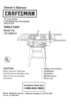
13" VARIABLE
SPEED
DRnLL
PRESS
MODEL
$CHEMATUC A
!3"
VAR_ADLE
SPEED
DRmLL PRESS
PARTS
LiST
MODEL
NO. 137.229130
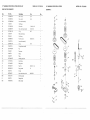
When servicing use onty CRAFTSMAN replacement parts. Use of any other parts may create a HAZARD or cause
product damage. Any attempt to repair or replace electrical parts on this Drill Press may create a HAZARD unless repair
is done by a qualified service technician. Repair service is available at your nearest Sears Service Center.
7A
Always order by PART NUMBER, not by key number
PARTS L_SY FOR SCHEMATIC
A
Description
Key
Pa#
No.
1
10400126
2A
10400401A_
3
2601BBDA72
Hex head bolt
4
10602204
Rack
1
5
10601901
Column lock handle
1
6
10600902
Worm
1
7A
10602304A1
Rack ring assembly
1
8A
1060t 009At
Crank handle assembly
1
9A
10401202A 1
Table brackef assembly
1
10
10602001
Table lock handle
t
11
10602138
Table
1
12A
10899201
Fence assembly
1
_"
S]zo
Qty
Base
l
Column assembly
1
M 10X 1.5-40
11
4
1o
I
[
•9A
NO. 137.229130
13" VARIABLE
SPEED
DRILL
PARTS LUST FOR SCHEMATIC
PRESS
PARTS
MODEL
LUST
NO. 137.229130
B
13" VARIABLE
SPEED
DRILL
PRESS
_ODEL
SCHEMATIC B
Key
Part No.
Description
Size
13
2668BBDA29
Pan head screw
M5X0.8-30
14
1046l 101
Plunger housing
15
2701QZD612
Hex. nut
1/2X20UNF T=6.5
1
16
2701QZD610
Hex, nut
1/2X2OUNF T= 10
1
17A
10605002A 1
Spring cap assembly
19
20
2574D55R06
2701FBD 107
O-ring rod
Hex. nut
21
10405401
Quill set screw
!
22
10408833
Switch box
1
23
2668BBDB94
Pan head screw
Qty
3
54
!
1
P6
M8X1.25 T=5
M5XO.8-50
1
1
4
,2..4
...................................
,2 g z..o.........................................
........................................................................................................
!..............
25A
2898 DB7G 12
Rocker switch
t
26
27
2806555 l P1
10216715
Lead wire assembly
Sticker
1
28
2668BZDA23
Pan head screw
M5X0.8-8
2
Tooth washer
5
2
29
2504MZC005
NO. 137.229130
52
1
44
,3o.
....................................
...............................................
r!n...........................................................................................................................
]..............
3t
14300102
Grip
3
32A
33
10404310A1
2603BBLA52
Handle assembly
Hex. socket set screw
t
M8X1.25-8
t
34
2603BBLA52
Hex. socket set screw
M8Xt ,25-8
1
35
2603BBLA56
Hex. socket set screw
M8X1.25,25
1
...................................................
36
37
106t 1201
Chuck key holder
, ................................................................................................................................................................................................................
2641BBDA40
Round washer head screw
M6X1.0-16
1
1
38
10419501
Screw bar
1
39
10409801
Speed bar seat
1
40
10419701
Shaft
i
41A
42
10409515A1
2677BBDAA5
Center pulley assembly
Pan head round neck screw
31
46
÷.........
1
M6X1.0-18
1
z{3........................ 250 t MWGN44
"F]'ai"w'asher
.................................
:................
:.....................................................................
]............
44
45
10419301 A1
260t BBDA44
Holder spec.
Hex. head bolt
46
47
2502ABC417
2801ABRF02
Spring washer
Strain relief
48
49A
2571 NNC501
8206226504
Woodruff key
Mo_r
t
1
50
51
2536MBE617
10402555
Spring pin
Head
2
52
53
10419001
10418901
Clamp handle
Collar
1
54
2668BBDA45
Pan head screw
55A
10409012A 1
Pulley cover
M6X1.0-35
6
1
4
5O
4
1
1
1
M6Xt .0-40
3O
3
27
20
8
17A
22
13" VARIABLE
SPEED
DRILL
PRESS
PARTS
LIST
MODEL
NO, 137.229130
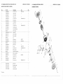
PARTS MST FOR SCHEMATIC C
13" VARIABLE
SPEED
DRILL
SCHEMATIC C
Key
Part No.
Descrip_on
$1ze
Qbi
56
2138MBL703
Hex. wrench
3-57
1
57
2138MBL704
Hex. wrench
4-64
l
58A
2807BB08HJA1
Power cable assembly
1
59
t 0463501
Shaft sleeve
!
60
250l NBDN 16
Flat washer
1/4X3/4-1/16
1
61
2602BBLW39
Hex. socket head cap bolt
M6X 1.0-12
1
62
2570ABN 142
C-ring
63
10402709
Bulb socket bracket
64
87404241
Cord clamp
65
2668BBDA25
Pan head screw
66
10450301A 1
Lamp socket assembly
67
2570BBN 130
C-ring
68A
! 0406501 At
Driving sleeve assembly
1
69
257! MNC318
Key
3
70
10463601
Spring cap
4
71
10463701
Spring
4
72
10407029
Pulley
4
73
2572ARW570
Variable speed belts
4
74A
2137103104
Chuck & key
1
75
21015M2J30
Drilling arbor
1
76
2701FZD109
Hex. Nut
M10X1,5
77
2502ABC410
Spring washer
10
78
10461702
Set ring
79
2602BBLA29
Hex. socket head cap bolt
80A
10661301A1
Set bolt assembly
1
8t
10607303
Wedge shifter
I
82A
10405606A2
Quill assembly
1
B-42
60
61
1
1
4
M5X20.8d 6
8
1
A-30
4
T=8
1
1
M5XO.8-30
)
I
1
i
,_ 59
PRESS
MODEL NO. 137.229130
t3"
VAR|ABLE
SPEED
DR_LL
PA_T$ LIST FOR SCHEMATIC
PRESS
PARTS
LiST
MODEL
NO, t37.229130
D (MOTOR)
13, VARIAE_LE,SPEED
SCHeMATiC
Key
Part NOo
Description
Size
Ch_
t
2668BBDBB3
Pan head screw
M4X0.7-t65
4
2
2504MBC004
Tooth washer
4
4
3
82042031!_
Front end ball
4
2504MZC005
Tooth washer
5
1
5
2668QZDK24
Pan head screw
10#X24UNC-1/4"
1
6
2001ZZ6203
Ball bearings
t
7
2990555B02
Contact plate
1
8
2504MBC005
Tooth washer
5
2
9
2668QBDK25
Pan head screw
10#X24UNC-3i8"
2
10
299155BA02
Centrifugal starter
1
11
2801DBHA01
Strain relief bushing
1
t2
82062121
Motor housing
t
13
t--9"722@'t-ggOt_ _o_b_-_4
Bi
Motor labd
1
14A
82062141 At
Stator assembly
1
15A
82042 t 51A 1
Rotor assembly
1
16
82041051
Fan
1
17
2001ZZ6202
Ball bearings
6202ZZ
1
18
2506MBN662
Wave washer
BWW6202
1
19
82061031
Rear end bell
20
2504MBC004
Tooth washer
21
2701FBD104
Hex nut
22
2668QZDK19
Pan head screw
5i32X32UNG1/4"
2
23
2801ABRF05
Rubber bushing
10
1
24
82061291
Capacitor terminal cover
25
28065558P7
Lead wire assembly
26
2668BZDA01
Pan head screw
27
82061301
Capacitor cover
1
28
2504NBC005
Tooth washer
2
29
2668QBDK22
Pan head screw
*
13722913002
Speed chart
1
*
13722913003
Specification label
1
*
13722913004
Warning labd
1
*
137229130002
Instruction manual
1
DRILL
PRESS
•
:i:
:
_ (MOTOr)
Oh
t
1
4
M4X0.7-3.2
4
4
1
1
M3X0.5-6
I 0#X24UNC-1/4"
2
2
* Not shown
i_ii:_,:::ii::i':;;ilf:!:i;:i::!!
,_!_
i_;::::_%:::i::_
i::i:;;:i:i_b:'_i:
¸_k:!_:
k::iiii¸k!?:iliI:':!IU,
I::::_!:i
;;i:!;::'i:::
i::i;:::!i:i;:;;::i!:01;:!i:!d_:i:i;i_,;:i
::i::ii::i:!i:ikf,
::;:: 26 ::::i!i_!i::;i_::!ii_i:i!;,:!!i
!_fli:;]:}i::!d
!!,i_:
:!:£!!:::,%d::&i;:i
_:}_::::!
:_::_;;::
:_
_:;_:
_::::_:_:?_
_::_;:_::::
_%:_%:_::_
:_::::?_:_b:::_:::_;_
_;:_b_:;:_
_:i_::_:%::_i:ii:i_::
/
:,; :::
MODELNO,
137,229130