1
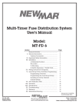
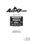
®
C.A.R.D. MODEL 060
INSTALLATION AND OPERATION MANUAL
SURVIVAL SAFETY ENGINEERING
INCORPORATED
321 NAVAL BASE ROAD
NORFOLK, VIRGINIA 23505
USA
Phone (757) 480-5508 Toll Free 888 475-5364
Email: [email protected]
www.survivalsafety.com
You have just purchased one of the most important devices
you will ever buy for your vessel.
®
C.A.R.D. Model 060, Collision Avoidance Radar Detector is
the finest Radar Detector on the market today.
It uses the same detector principles as the Model 100 Units
that have performed so well under rigorous conditions for
the U.S. Navy.
WARNING !
This device is intended for use as an aid to collision
avoidance only. It does not in any way, relieve or reduce the
responsibility of the Captain of the vessel for maintaining a
proper watch at all times when underway as described in the
Code of Federal Regulations and International Maritime
Law.
C.A.R.D. SYSTEM COMPONENTS
The Antenna with a standard 25 foot cable
The Display Unit (Control Module)
This Manual
INDEX:
Warning
Page 2
Components
Page 3
How your C.A.R.D. system works
Page 4
Antenna Installation
Page 5,6
Antenna Unit
Page 7
Control Module Warning
Page 8
Control Module
Page 9
Operation
Page 10,11
Remote
Page 11
Pin Out
Page 12
Test
Page 13
Notes
Page 14
Warranty
Page 15
Page# 3
The antenna portion of the unit has four directional receivers
that correspond to the four relative display lights on the
control unit. A ship operating radar in a frequency from 3 to
10 centimeters emits a stream of mcrowave pulses as their antenna rotates. When these pulses strike one or more of the
detectors in the C.A.R.D. antenna, they are processed to light up
the corresponding display. The intensity of the signal will
determine the number of lights that will be illuminated.
When the top light bar (zero degrees relative bearing lights ), it
tells you that a target is off your bow, when the light bar at three
O’clock (ninety degrees relative bearing lights ), it tells you that
a target is on your starboard beam. If both top and three O’clock
light bars go on simultaneously and the same number of lights
within the bar are illuminated, they tell you that your target is
approximately 45 degrees off your starboard bow, and so on
around the display .
The C.A.R.D. Radar Detector cannot determine the distance a
scanning ship is away from your vessel, but since radar pulses
are microwaves that travel in straight lines, the maximum range
is a factor of the height of the ship’s radar and your vessel’s
antenna. Remember that more than one ship can be scanning your
vessel at the same time. Experience with your C.A.R.D. System
will quickly enable you to recognize the characteristics of
different situations.
Your Radar Detector can be safely operated at the same time
your own radar is scanning, provided the the detector’s antenna is
installed correctly. The C.A.R.D. antenna may NOT be installed
next to your radar antenna or at the same height. It is best to find
a location as distant as possible from any transmitting antennas .
It is possible that pulses from your own radar could activate the
Radar Detector by reflecting off nearby obstacles on your vessel
as well as other ships or nearby coast lines.
Page# 4
Unit Installation
If you chose to have someone install the C.A.R.D. system for
you, ensure that this manual is available to them. It contains
important installation information which may or may not be
familiar to the service personnel. Save this manual for future
reference.
Technical Support Group is at your service anytime at:
1- 888 - 475 -5364
The C.A.R.D. system antenna unit should be mounted so as to
be free of obstructions as possible . The antenna should be
oriented with the vessel so that the cross-hair labeled FWD on
the antenna dome is pointing toward the bow of the vessel and if
not on the vessel’s centerline, parallel with the centerline of the
vessel . The unit should be mounted with the base of the antenna
down. Mounting the antenna upside down will result in the alarm
displayed on the opposite side of the vessel on the display unit .
If such a mounting procedure is applicable to your needs, contact
Survival Safety Engineering for technical assistance.
When choosing a location for the mounting the C.A.R.D. System
Antenna ensure that the mounting surface has adequate strength
to support the antenna. Check the area for possible obstructions,
both to mounting and to reception.
Make sure that the antenna will not be mounted in the beam path
of an existing radar or mounted so that it might interfere with
installation and operation of a radar in the future. One of the best
locations is on the stern rail. This can be accomplished with a
rail mount and a short extension. Raise the antenna above the
cabin top to clear as many obstructions as possible.
Page# 5
For the antenna cable installation, you have three options :
1) Determine a cable route that does not require deck penetration;
or
2) Cut the cable to permit deck penetration , and rejoin the cable
using NEWMAR splash proof junction box Model BX-1 or
equivalent available at your local marine supply store;
or
3) If you choose not to cut the cable, you may use a waterproof
cable feed-through deck fitting for use with cable with installed
cable connector, NEWMAR Model CCX-P or equivalent, also
available at your local marine supply store.
Ensure that the antenna unit will be adequately protected from
lines that may foul on the unit and either damage the cable or the
antenna unit.
Plan a route for the connecting cable to the display unit, ensuring
the cable is of adequate length to reach the rear of the display unit
without putting tension on the cable. Also insure the cable is
fastened securely so it will not become caught in nearby
machinery. Try to avoid running the connecting cable in close
proximity to power cords or generators carrying alternating
current. The recomended procedure is to temporarily install all
components of the antenna on the vessel in the planned positions.
Check to ensure the unit functions properly and receives only
minimal interference from other transmitting equipment,
including any marine band or CB radios on the vessel.
If the location proves to be inadequate due to interference, find
another more suitable location. If the location proves to be
adequate, attach it permanently in position . This is accomplished
by fastening the antenna unit base securely to the mounting
surface , and then securing the antenna unit to the base .
Most threaded antenna mounts are accepted by the base .
Secure the connecting cable along the planned route so as to not
interfere with anything.
Page# 6
ANTENNA
Stern Rail Mount preferred
Antenna Mounts available at most marine stores
Page# 7
CONTROL MODULE
WARNING
The Display Module IS NOT WATER RESISTANT !
When choosing a location find one that remains dry.
Your navigation station should qualify.
Mount the control module in a convenient location where you
can observe the display .
Connect the power cable to a reliable power source of 12 volts
D.C..
It is suggested that you run the power cable to your distribution
panel and not parallel to any other circuits .
Connect the red wire to positive and the black wire to the ground.
For further protection a 1/4 amp fuse can be installed either in
line or at the distribution panel.
Page# 8
DISPLAY CONTROL MODULE
7 5/8
©
Marine
Radar Detector
Survival Safety Enginee ring, I nc.
ON
AUDIO
HI
OFF
LOW
M ODEL 060
Audi o
Gain
Control
Heads-Up
Display
Display
Bars
Power / Antenna Cable
Page# 9
The control panel has a dial that when turned clockwise will
activate the system and sets the level of sensitivity.The toggle
switch will select the level of audio desired.
Since radar transmissions travel line-of-sight, the distance at
which a target is detected is dependent primarily on two factors :
the height of the transmitting antenna and the height of your
receiving antenna...Thus, if the C.A.R.D. antenna is mounted on
your stern rail and has an unobstructed view of 5 to 15 miles you
should receive an indication if there are any radar emitting ships
in the area.
Another factor affecting range is the power of the other ship’s
transmitting radar. Do not assume that a weak signal is distant
and a strong signal is close. A very powerful radar several miles
away can be of equivalent signal straight as a small radar on a low
range setting. Keeping in mind the fact that a C.A.R.D. does not
finitely measure range, overall range reception is adjustable by
changing the sensitivity control knob.
Although, as this discussion indicates, a specific maximum range
cannot be determined without knowing all the factors, experience
has shown that approximate ranges of 35 miles are attainable.
You should also bear in mind the visual distance to your horizon
is also a function of your height of eye. Therefore it will serve a
little useful purpose to detect a ship at 30 miles if it never closes
to within your visual sighting range, let alone becomes a collision
threat .
It is also important to note that a powerful transmitting Radar
Unit fairly close aboard will saturate the system, however, by
rotating the sensitivity knob clockwise, a more accurate direction
can be determined.
Further, if you are transiting near a steep coastline and are
illuminated by a ship outboard of you, you may get an indicator
Page# 10
light from the signal reflected from the coast as well as one from
the primary source. Again, by rotating the sensitivity knob a few
degrees clockwise, the reflected signal should disappear.
A remote horn can be installed using the pin #7 of the antenna
plug.
Remove the shell covering plug.
Locate pin #7 (this is the only one without a wire).
Connect a wire to the negitive side of the buzzer.
The positive side of the buzzer is connected to the positive side of
your battery.
We recommend that you install an on-off switch in the 12 volt
line, to turn off the remote when not needed.
For help with this installation please call SSE for assitance at:
1 - 888 - 475-5364
Voice: 757 - 480-5508
www.survivalsafety.com
[email protected]
Page# 11
Pin
Page# 12
#1
Red
(B= to the antenna )
#2
Blue
Aft Detector
#3
White
Stbd Detector
#4
Green
Port Detector
#5
Brown
Fwd Detector
#6
Black
Power B-
#7
NC
Negative for external alarm
#8
Red
Power B+
#9
Black
(B- to the antenna )
Double check that all connections are secure and are set up
according to the instructions. Turn the sensitivity control knob
clockwise until all segments of the display are lit, then continue to
turn the sensitivity control clockwise until all the indicator lights
go out. The point where the lights just extinguish is the point of
the highest sensitivity. This is much like setting the squelch on a
VHF Marine Radio. If a light stays on steadily, it indicates that
the sensitivity adjustment knob on the control module is set too
high, or there is a fault within the system.
Should you experience a problem with your C.A.R.D. System,
please call Survival Safety Engineering directly. We have
personnel that are specifically trained to help you at.
1- 888 - 475 - 5364
Safe Sailing ,
The Crew at Survival Safety Engineering
Page# 13
NOTES
Page# 14
SSE C.A.R.D. Model 060 Instruction Ops. Manual Rev. 2003
WARRANTY
Survival Safety Engineering, Incorporated
Two Year Limited Warranty
Every Survival Safety Engineering (SSE) C.A.R.D. Model 060 is
thoroughly inspected and tested before leaving the factory. It is
warranted to be free of defects from workmanship and materials
for the period of TWO YEARS from the date of orignal purchase.
Should any trouble develope during this two year period, return the
COMPLETE unit, freight prepaid, to the company at: 321 Naval
Base Road, Norfolk, Virginia 23505. If inspection shows the trouble
is caused by defective workmanship or material, SSE will repair, or
at our option, replace without charge.
This Warranty does not apply where:
♦
repairs have been made or attempted by others
♦
repairs are required because of normal wear and tear
♦
the unit has been abused, misused or improperly installed
♦
alterations have been made to the unit
In no event shall SSE be liable for any indirect, incidental or
consequential damages from the sale or use of the unit. This
disclaimer applies both during and after the term of warranty.
SSE disclaims liability for any implied warranties, including
implied warranties of “merchantability” and “fitness for a specific
purpose”, after the two year term of this warranty.
Some states do not allow the exclusion or limitation of incidental or
consequential damages, so the above limitation or exclusion may
Not apply to you.
Page# 15