1
Ethernet
Network
Adapters
®
AT-2450FTX, AT-2451FTX,
AT-2700FX, AT-2701FX,
AT-2700FTX, AT-2701FTX,
AT-2745FX, AT-2746FX
Installation
Guide
PN 613-50669-00 Rev A
Copyright © 2005 Allied Telesyn, Inc.
3200 North First Street, San Jose, CA 95134 USA
All rights reserved. No part of this publication may be reproduced without prior written permission from Allied Telesyn, Inc.
Microsoft is a registered trademark of Microsoft Corporation, Netscape Navigator is a registered trademark of Netscape
Communications Corporation. All other product names, company names, logos or other designations mentioned herein are
trademarks or registered trademarks of their respective owners.
Allied Telesyn, Inc. reserves the right to make changes in specifications and other information contained in this document without
prior written notice. The information provided herein is subject to change without notice. In no event shall Allied Telesyn, Inc. be
liable for any incidental, special, indirect, or consequential damages whatsoever, including but not limited to lost profits, arising
out of or related to this manual or the information contained herein, even if Allied Telesyn, Inc. has been advised of, known, or
should have known, the possibility of such damages.
Electrical Safety and Emissions Standards
This product meets the following standards.
U.S. Federal Communications Commission
Declaration of Conformity
Manufacturer Name: Allied Telesyn, Inc.
Declares that the product: Network Adapter Cards
Model Numbers: AT-2450FTX, AT-2451FTX, AT-2700FX, AT-2701FX, AT-2700FTX, AT-2701FTX, AT-2745FX,
AT-2746FX
These products comply with FCC Part 15B, Class B Limits:
These devices comply with part 15 of the FCC Rules. Operation is subject to the following two conditions: (1) This device
must not cause harmful interference, and (2) this device must accept any interference received, including interference
that may cause undesired operation.
Radiated Energy
Note: This equipment has been tested and found to comply with the limits for a Class B digital device pursuant to Part 15
of FCC Rules. These limits are designed to provide reasonable protection against harmful interference in a residential
installation. This equipment generates, uses and can radiate radio frequency energy and, if not installed and used in
accordance with instructions, may cause harmful interference to radio or television reception, which can be determined
by turning the equipment off and on. The user is encouraged to try to correct the interference by one or more of the
following measures:
-
Reorient or relocate the receiving antenna.
-
Increase the separation between the equipment and the receiver.
-
Connect the equipment into an outlet on a circuit different from that to which the receiver is connected.
-
Consult the dealer or an experienced radio/TV technician for help.
Changes and modifications not expressly approved by the manufacturer or registrant of this equipment can void your
authority to operate this equipment under Federal Communications Commission rules.
Industry Canada
This Class Bdigital apparatus meets all requirements of the Canadian Interference-Causing Equipment Regulations.
Cet appareil numérique de la classe B respecte toutes les exigences du Règlement sur le matériel brouilleur du Canada.
RFI Emissions
EN55022 Class B, EN61000-3-2, EN61000-3-3
Immunity
EN55024
Electrical Safety
EN60950 (TUV), UL 60950 (CULUS)
Laser Safety
EN60825
3
Translated Safety Statements
Important: Appendix E contains translated safety statements for installing this equipment. When
you see the , go to Appendix E for the translated safety statement in your language.
Wichtig: Anhang E enthält übersetzte Sicherheitshinweise für die Installation dieses Geräts. Wenn
Sie sehen, schlagen Sie in Anhang E den übersetzten Sicherheitshinweis in Ihrer Sprache nach.
Importante: El Apéndice E contiene mensajes de seguridad traducidos para la instalación de este
equipo. Cuando vea el símbolo , vaya al Apéndice E para ver el mensaje de seguridad traducido
a su idioma.
Important : L'annexe E contient les instructions de sécurité relatives à l'installation de cet
équipement. Lorsque vous voyez le symbole , reportez-vous à l'annexe E pour consulter la
traduction de ces instructions dans votre langue.
Importante: l’Appendice E contiene avvisi di sicurezza tradotti per l’installazione di questa
apparecchiatura. Il simbolo , indica di consultare l’Appendice E per l’avviso di sicurezza nella
propria lingua.
Важно: Приложение E содержит переведенную инструкцию по безопасности при установке
данного устройства. Если Вы встретите , перейдите к Приложению E для получения
переведенной инструкции по безопасности.
4
Contents
Preface ................................................................................................................................................................................. 9
Document Conventions ....................................................................................................................................................... 10
Where to Find Web-based Guides ...................................................................................................................................... 11
Contacting Allied Telesyn .................................................................................................................................................... 12
Online Support ..............................................................................................................................................................12
Email and Telephone Support .......................................................................................................................................12
Returning Products........................................................................................................................................................12
For Sales or Corporate Information ...............................................................................................................................12
Adapter Card Driver Updates ........................................................................................................................................12
Chapter 1: Network Adapter Card Overview .................................................................................................................. 13
Overview.............................................................................................................................................................................. 14
AT-2450FTX and AT-2451FTX Series ................................................................................................................................ 16
Specifications ................................................................................................................................................................17
LEDs..............................................................................................................................................................................20
AT-2700FX and AT-2701FX Series..................................................................................................................................... 21
Specifications ................................................................................................................................................................22
LED ...............................................................................................................................................................................24
AT-2700FTX and AT-2701FTX Series ................................................................................................................................ 25
Specifications ................................................................................................................................................................26
LEDs..............................................................................................................................................................................28
AT-2745FX and AT-2746FX Series..................................................................................................................................... 30
Specifications ................................................................................................................................................................31
LEDs..............................................................................................................................................................................34
Additional Features.............................................................................................................................................................. 35
Wake on LAN ................................................................................................................................................................35
Driver Installation and the AT-Setup Utility....................................................................................................................36
Virtual LANs and the AT-MUX Protocol.........................................................................................................................37
Operating Statistics and the AT-Stat Utility ...................................................................................................................38
Diagnostics and the AT-Diag Utility ...............................................................................................................................39
Load Balancing and Fail-over Protection ......................................................................................................................39
Managed Boot Agent.....................................................................................................................................................43
Chapter 2: Installing a Network Adapter Card ............................................................................................................... 45
Verifying Package Contents ................................................................................................................................................ 46
Reviewing Safety Precautions ............................................................................................................................................. 47
Installing the Low Profile Bracket......................................................................................................................................... 48
Installing a Network Adapter Card ....................................................................................................................................... 51
Chapter 3: Microsoft Windows 2000, 2003, and XP ....................................................................................................... 57
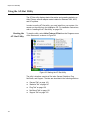
Choosing a Network Adapter Card Driver ........................................................................................................................... 58
Installing or Updating a Driver Using the AT-Setup Utility ................................................................................................... 59
AT-Setup Guidelines .....................................................................................................................................................59
Running AT-Setup from the Installation CD ..................................................................................................................60
Running AT-Setup from a Driver Installation Diskette ...................................................................................................66
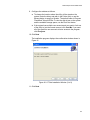
Creating a Driver Installation Disk ....................................................................................................................................... 68
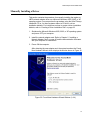
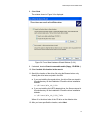
Manually Installing a Driver.................................................................................................................................................. 73
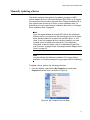
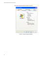
Manually Updating a Driver ................................................................................................................................................. 77
Removing a Driver ............................................................................................................................................................... 85
Running AT-Setup to Complete Driver Installation .............................................................................................................. 90
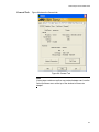
Configuring the Network Adapter Card Settings.................................................................................................................. 91
5
Contents
Configuring the IP Address, Subnet Mask, and Gateway Address .............................................................................. 92
Configuring Additional Network Adapter Card Settings ................................................................................................ 96
Chapter 4: Microsoft Windows NT 4.0 .......................................................................................................................... 107
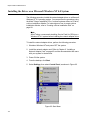
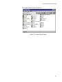
Installing the Driver on a Microsoft Windows NT 4.0 System ............................................................................................ 108
Removing the Driver from a Windows NT 4.0 System....................................................................................................... 115
Chapter 5: Novell Netware 6.5 ....................................................................................................................................... 119
Installing the Network Adapter Driver on a Novell NetWare 6.5 System ........................................................................... 120
Files Needed for Installation ....................................................................................................................................... 120
New Server Installation............................................................................................................................................... 120
Manual Installation...................................................................................................................................................... 121
Multiple Adapters ........................................................................................................................................................ 122
Removing an Adapter Driver from Novell Netware 6.5 Server ................................................................................... 123
Chapter 6: Linux 2.4 and 2.6 .......................................................................................................................................... 125
Installing the ATNIC Driver on Linux 2.4............................................................................................................................ 126
Limitations .................................................................................................................................................................. 126
Building the Driver ...................................................................................................................................................... 126
Installing the Driver ..................................................................................................................................................... 126
Dynamic Loading ........................................................................................................................................................ 127
Changing Configuration Settings ................................................................................................................................ 127
Setting the Adapter’s Speed and Duplex Mode on Linux 2.6 ............................................................................................ 128
Phase 1 ...................................................................................................................................................................... 128
Phase 2 ...................................................................................................................................................................... 128
Chapter 7: Solaris 9 ........................................................................................................................................................ 129
Supported Operating System............................................................................................................................................. 130
Installing the Driver ............................................................................................................................................................ 130
Configuring the Network Adapter Card .............................................................................................................................. 131
Removing the Driver .......................................................................................................................................................... 132
Chapter 8: AT-Stat Utility ............................................................................................................................................... 133
Installing the AT-Stat Utility................................................................................................................................................ 134
Installing with a CD Drive............................................................................................................................................ 134
Installing without a CD Drive....................................................................................................................................... 140
Using the AT-Stat Utility..................................................................................................................................................... 142
Starting the AT-Stat Utility .......................................................................................................................................... 142
General Tab................................................................................................................................................................ 143
Statistics Tab .............................................................................................................................................................. 147
Ping Tab ..................................................................................................................................................................... 150
NetCheck Tab............................................................................................................................................................. 151
Support Tab ................................................................................................................................................................ 152
Removing the AT-Stat Utility.............................................................................................................................................. 153
Chapter 9: AT-MUX Multiple VLAN Protocol ................................................................................................................ 157
AT-MUX Protocol Overview ............................................................................................................................................... 158
Installing the AT-MUX Protocol.......................................................................................................................................... 162
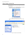
Adding, Changing, or Deleting VIDs .................................................................................................................................. 168
Removing the AT-MUX Protocol........................................................................................................................................ 173
Chapter 10: AT-Diag Utility ............................................................................................................................................ 175
Starting the AT-Diag Utility................................................................................................................................................. 176
Diagnostics Tests Option ................................................................................................................................................... 179
Communications Test Option............................................................................................................................................. 181
Hardware Information Option............................................................................................................................................. 183
Settings Option .................................................................................................................................................................. 184
Speed/Duplex Selection ............................................................................................................................................. 184
Default Port................................................................................................................................................................. 184
BootROM .................................................................................................................................................................... 185
Select Adapter Option........................................................................................................................................................ 186
Technical Support Option .................................................................................................................................................. 187
6
Network Adapter Card Installation Guide
Chapter 11: Troubleshooting ......................................................................................................................................... 189
Appendix A: Technical Specifications .......................................................................................................................... 193
Physical Specifications ...................................................................................................................................................... 193
Operating Voltage.............................................................................................................................................................. 193
Environmental Specifications............................................................................................................................................. 193
Electrical Safety and Emissions Standards ....................................................................................................................... 194
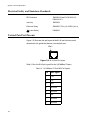
Twisted Pair Port Pin-outs ................................................................................................................................................. 194
Appendix B: Unattended Microsoft Windows Installations ........................................................................................ 195
Unattended Microsoft Windows XP Installation ................................................................................................................. 196
What the Steps Do ......................................................................................................................................................196
Unattended Setup .......................................................................................................................................................196
Appendix C: Optional BootPROM Chip and DIP Switch Settings .............................................................................. 199
Installing a BootPROM Chip .............................................................................................................................................. 200
DIP Switch Settings ........................................................................................................................................................... 202
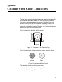
Appendix D: Cleaning Fiber Optic Connectors ........................................................................................................... 203
Using a Cartridge-Type Cleaner ........................................................................................................................................ 204
Using a Swab .................................................................................................................................................................... 206
Appendix E: Translated Safety Statements ................................................................................................................. 209
Index ................................................................................................................................................................................ 235
7
Contents
8
Preface
This guide contains installation instructions for the following Allied Telesyn
network adapter card series:
AT-2450FTX
AT-2451FTX
AT-2700FX
AT-2701FX
AT-2700FTX
AT-2701FTX
AT-2745FX
AT-2746FX
Note
The AT-2450FTX, AT-2700FX, AT-2700FTX, and AT-2745FX Series
are no longer available from Allied Telesyn and have been replaced
by the AT-2451FTX, AT-2701FX, AT-2701FTX, and AT-2746FX
Series, respectively. They are described in this guide for reference
purposes for those networks where the cards are already installed.
9
Preface
Document Conventions
This guide uses the following conventions:
Note
Notes provide additional information.
Caution
Cautions inform you that performing or omitting a specific action
may result in equipment damage or loss of data.
Warning
Warnings inform you that performing or omitting a specific action
may result in bodily injury.
10
Network Adapter Card Installation Guide
Where to Find Web-based Guides
The installation and user guides for all Allied Telesyn products are
available in Portable Document Format (PDF) from our web site at
www.alliedtelesyn.com. You can view the documents on-line or
download them onto a local workstation or server.
11
Preface
Contacting Allied Telesyn
This section provides Allied Telesyn contact information for technical
support as well as sales or corporate information.
Online Support
You can request technical support online by accessing the Allied Telesyn
Knowledge Base from the following web site: www.alliedtelesyn.com/kb.
You can use the Knowledge Base to submit questions to our technical
support staff and review answers to previously asked questions.
Email and
Telephone
Support
For Technical Support via email or telephone, refer to the Support &
Services section of the Allied Telesyn web site: www.alliedtelesyn.com.
Returning
Products
Products for return or repair must first be assigned a Return Materials
Authorization (RMA) number. A product sent to Allied Telesyn without a
RMA number will be returned to the sender at the sender’s expense.
To obtain a RMA number, contact Allied Telesyn’s Technical Support at
our web site: www.alliedtelesyn.com.
For Sales or
Corporate
Information
Adapter Card
Driver Updates
You can contact Allied Telesyn for sales or corporate information at our
web site: www.alliedtelesyn.com. To find the contact information for your
country, select Contact Us -> Worldwide Contacts.
You can download new releases of network adapter card drivers from
either of the following Internet sites:
❑ Allied Telesyn web site: www.alliedtelesyn.com
❑ Allied Telesyn FTP server: ftp://ftp.alliedtelesyn.com
To download new firmware from the Allied Telesyn FTP server using your
workstation’s command prompt, you will need FTP client software and you
must log in to the server. Enter “anonymous” as the user name and your
email address for the password.
12
Chapter 1
Network Adapter Card Overview
This chapter describes the features of the Allied Telesyn network adapter
cards. Sections in the chapter include:
“Overview” on page 14
“AT-2450FTX and AT-2451FTX Series” on page 16
“AT-2700FX and AT-2701FX Series” on page 21
“AT-2700FTX and AT-2701FTX Series” on page 25
“AT-2745FX and AT-2746FX Series” on page 30
“Additional Features” on page 35
13
Chapter 1: Network Adapter Card Overview
Overview
The Allied Telesyn Ethernet network adapter cards are designed to
simplify the task of building a new 10 Mbps or 100 Mbps Ethernet network
or expanding an existing one. Offered in a variety of port configurations,
these adapters give you the power and flexibility to build an Ethernet
network suited to the unique requirements of your business environment.
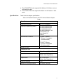
Table 1 lists the port configurations of the network adapter card series
described in this guide.
Table 1. Port Configurations
Twisted Pair
Port
Series
Fiber Optic
Port
Second Fiber
Optic Port
AT-2450FTX
10/100Base-TX
10Base-FL
-
AT-2451FTX
10/100Base-TX
10Base-FL
-
AT-2700FX
-
100Base-FX
-
AT-2701FX
-
100Base-FX
-
AT-2700FTX
10/100Base-TX
100Base-FX
-
AT-2701FTX
10/100Base-TX
100Base-FX
-
AT-2745FX
-
10Base-FL
100Base-FX
AT-2746FX
-
10Base-FL
100Base-FX
Note
The AT-2450FTX, AT-2700FX, AT-2700FTX, and AT-2745FX Series
are no longer available from Allied Telesyn. They have been
replaced by the AT-2451FTX, AT-2701FX, AT-2701FTX, and
AT-2746FX Series, respectively. They are described in this guide for
reference purposes for those networks where the cards are already
installed.
As shown in Table 1, most of the network adapter cards discussed in this
manual are dual port adapters. A dual port card has either a twisted pair
port and a fiber optic port or two fiber optic ports.
Dual port adapters can simplify the installation and maintenance of your
network because the same network adapter card can be used for either
twisted pair cable or fiber optic cable. This eliminates the need of
purchasing different cards for different cable media and so reduces the
number of types of adapters needed to build your network.
14
Network Adapter Card Installation Guide
Dual port adapters also simplify the task of relocating nodes in a network.
When a node is moved to a new location that also involves a change to the
media connection, such as from twisted pair cable to fiber optic cable, no
change to the adapter is necessary since the adapter has ports for both
types of medium.
Selecting which port to use on a dual port adapter is usually dictated by
the distance of the node from the Ethernet switch of hub or the working
environment. The maximum operating distance for the twisted pair port is
100 meters, typically making this port appropriate for nodes within that
operating distance from the Ethernet switch or hub.
The fiber optic port is appropriate for nodes that are greater than 100
meters from the switch or hub or in working environments where
electromagnetic emissions from manufacturing or other heavy equipment
could affect network transmissions over twisted pair cabling.
All of the adapters described in this guide use the same network adapter
card drivers. This further simplifies the task of network maintenance by
reducing the number of drivers you need to maintain.
15
Chapter 1: Network Adapter Card Overview
AT-2450FTX and AT-2451FTX Series
The adapters in the AT-2450FTX Series are:
AT-2450FTX/SC
AT-2450FTX/ST
The adapters in the AT-2451FTX Series are:
AT-2451FTX/SC
AT-2451FTX/ST
These are dual port adapters. They feature a twisted pair port and a fiber
optic port. The twisted pair port has a standard RJ-45 connector and
operates at either 10 or 100 Mbps (10Base-T/100Base-TX), half- or fullduplex mode. The adapter features Auto-Negotiation, which allows the
network adapter port to automatically set its speed and duplex mode to
match the settings of the port on the remote device, such as an Ethernet
switch or hub.
The second port is a fiber optic port with either a duplex SC or duplex ST
connector, depending on the model. This port has a fixed operating speed
of 10 Mbps (10Base-FL), half- or full-duplex mode. The default setting is
full-duplex. The duplex mode must be set manually.
Note
You can use only one port on this adapter at a time. Do not attach
both ports to the network at the same time.
Differences between the two series are:
16
The AT-2450FTX Series is PCI 2.1-compliant.
The AT-2451FTX Series is PCI 2.2-compliant.
The AT-2450FTX Series was offered in two versions — a standard
version and a low profile version for systems that accept only low
profile adapters.
The AT-2451FTX Series can be installed in either a standard or low
profile system. The adapter comes with two brackets, one for a
standard system and another for a low profile system.
The BootPROM and Managed Boot Agent (MBA) were optional with
the AT-2450FTX Series.
The BootPROM and MBA come standard with the AT-2451FTX
Series.
Network Adapter Card Installation Guide
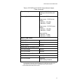
Specifications
The AT-2450FTX Series supported the Wake on LAN feature only on
the twisted pair port.
The AT-2451FTX Series supports the Wake on LAN feature on both
ports.
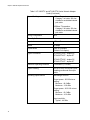
Table 2 lists the adapter specifications.
Table 2. AT-2450FTX and AT-2451FTX Series Network Adapter
Cards
Basic Features
Supported Platforms
IBM PC or compatible
Supported Operating Systems
Microsoft Windows 2000
Microsoft Windows 2003
Microsoft Windows XP
Microsoft Windows NT 4.0
Novell Netware 6.5
Linux 2.4 and 2.6
Solaris 9
Motherboard Connector
AT-2450FTX Series:
PCI bus 2.1-compliant
(32-bit bus width)
AT-2451FTX Series:
PCI bus 2.2-compliant
(32-bit bus width)
Number of Ports
2
Twisted Pair Port
Standards
10Base-T and 100Base-TX
Speed
10 Mbps or 100 Mbps
(Default: Auto-Negotiation)
Duplex Mode
Half- or full-duplex
(Default: Auto-Negotiation)
Type of Connector
RJ-45
Maximum Operating Distance
100 meters (328 feet)
17
Chapter 1: Network Adapter Card Overview
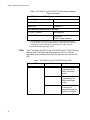
Table 2. AT-2450FTX and AT-2451FTX Series Network Adapter
Cards (Continued)
Type of Cabling
10Base-T operation:
Category 3 or better 100 ohm
shielded or unshielded twisted
pair cable
100Base-TX operation:
Category 5 or better 100 ohm
shielded or unshielded twisted
pair cable
Wiring Configuration
MDI
Fiber Optic Port
Standard
10Base-FL
Speed
10 Mbps
Duplex Mode
Half- or full-duplex
(Default: Full-duplex)
Type of Connector
AT-2450FTX/SC - duplex SC
AT-2450FTX/ST - duplex ST
AT-2451FTX/SC - duplex SC
AT-2451FTX/ST - duplex ST
Maximum Operating Distance1
2 kilometers (1.2 miles)
Type of Cabling
50/125 or 62.5/125 micron (core/
cladding) multimode fiber optic
cable
Operating Specifications
Wavelength: 820 nm
Output power - 50/125 micron
cabling:
Minimum: -18.8 dBm
Maximum: -13.8 dBm
Output power - 62.5/125 micron
cabling:
Minimum: -15.0 dBm
Maximum: -10.0 dBm
Input sensitivity:
Typical: -4.4 dBm
18
Network Adapter Card Installation Guide
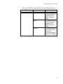
Table 2. AT-2450FTX and AT-2451FTX Series Network Adapter
Cards (Continued)
Wake on LAN Feature
AT-2450FTX Series
Supported on twisted pair port
only.
AT-2451FTX Series
Supported on both twisted pair
port and fiber optic port.
Default Setting
Disabled
BootPROM Chip and MBA Feature
AT-2450FTX Series
Optional
AT-2451FTX Series
Standard
Default Port
10/100Base-TX
Load Balancing and Fail-over Protection
AT-2450FTX Series
Not supported
AT-2451FTX Series
Supported2
Default setting: Disabled
1. Numerous factors, such as too many splices or poorly implemented splices,
can significantly reduce the maximum distance of a fiber optic port. Fiber optic
cable should only be installed by a qualified fiber optic cable contractor.
2. Microsoft Windows 2000, 2003, and XP.
19
Chapter 1: Network Adapter Card Overview
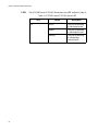
LEDs
Table 3 describes the LEDs for the ports on the AT-2450FTX and
AT-2451FTX Series. The twisted pair port uses the 10 or 100 LED,
depending on its operating speed. The fiber optic port uses just the 10
LED.
Table 3. AT-2450FTX and AT-2451FTX Series LEDs
LED
10
100
20
Status
Description
Green
The twisted pair port
or fiber optic port is
operating at 10 Mbps,
full-duplex mode.
Amber
The twisted pair port
or fiber optic port is
operating at 10 Mbps,
half-duplex mode.
Flashing
The twisted pair port
or fiber optic port is
receiving or
transmitting network
packets at 10 Mbps.
Green
The twisted pair port
is operating at 100
Mbps, full-duplex
mode.
Amber
The twisted pair port
is operating at 100
Mbps, half-duplex
mode.
Flashing
The twisted pair port
is receiving or
transmitting network
packets at 100 Mbps.
Network Adapter Card Installation Guide
AT-2700FX and AT-2701FX Series
The adapters in the AT-2700FX Series are:
AT-2700FX/SC
AT-2700FX/ST
AT-2700FX/MT
AT-2700FX/VF
The adapters in the AT-2701FX Series are:
AT-2701FX/SC
AT-2701FX/ST
AT-2701FX/MT
AT-2701FX/VF
These adapters feature a single fiber optic port with a fixed operating
speed of 100 Mbps with half- or full-duplex operation. The port has a
maximum operating distance of 2 kilometers in full-duplex mode and uses
50/125 or 62.5/125 micron (core/cladding) multimode fiber optic cable.
Maximum operating distance will be less for half-duplex mode.
These adapters are appropriate in network environments where the
distance between an end node and an Ethernet hub or switch is more than
100 meters, the maximum allowed for twisted pair cable, or in
manufacturing areas or other heavy equipment environments where
electromagnetic emissions could interfere with nodes connected with
twisted pair cable.
Differences between the two series are:
The AT-2700FX Series is PCI 2.1-compliant.
The AT-2701FX Series is PCI 2.2-compliant.
The AT-2700FX Series was offered in two versions — a standard
version and a low profile version for systems that accept only low
profile adapters.
The AT-2701FX Series can be installed in either a standard or low
profile system. The adapter comes with two brackets, one for a
standard system and another for a low profile system.
The BootPROM chip and MBA were optional with the AT-2700FX
Series.
The BootPROM chip and MBA come standard with the AT-2701FX
Series.
21
Chapter 1: Network Adapter Card Overview
Specifications
Table 4 lists the adapter specifications.
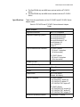
Table 4. AT-2700FX and AT-2701FX Series Network Adapter
Cards
Basic Features
Supported Platforms
IBM PC or compatible
Supported Operating Systems
Microsoft Windows 2000
Microsoft Windows 2003
Microsoft Windows XP
Microsoft Windows NT 4.0
Novell Netware 6.5
Linux 2.4 and 2.6
Solaris 9
Motherboard Connector
AT-2700FX Series:
PCI bus 2.1-compliant
(32-bit bus width)
AT-2701FX Series:
PCI bus 2.2-compliant
(32-bit bus width)
Number of Ports
1
Fiber Optic Port
Standard
100Base-FX
Speed
100 Mbps
Duplex Mode
Half- or full-duplex
(Default: full-duplex)
Type of Connector
AT-2700FX Series:
AT-2700FX/SC - duplex SC
AT-2700FX/ST - duplex ST
AT-2700FX/MT - MT-RJ
AT-2700FX/VF - VF-45
AT-2701FX Series
AT-2701FX/SC - duplex SC
AT-2701FX/ST - duplex ST
AT-2701FX/MT - MT-RJ
AT-2701FX/VF - VF-45
Maximum Operating Distance1
22
2 kilometers (1.2 miles) in fullduplex mode
412 meters (1236 feet) in halfduplex mode
Network Adapter Card Installation Guide
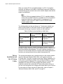
Table 4. AT-2700FX and AT-2701FX Series Network Adapter
Cards (Continued)
Type of Cabling
50/125 or 62.5/125 micron (core/
cladding) multimode fiber optic
cable
Operating Specifications
Wavelength: 1310 nm
Output power - 50/125 micron
cabling:
Minimum: -22.5 dBm
Maximum: -14 dBm
Output power - 62.5/125 micron
cabling:
Minimum: -19.0 dBm
Maximum: -14 dBm
Input sensitivity:
Minimum: -31 dBm
Maximum: -14 dBm
Wake on LAN Feature
AT-2700FX Series
Supported
AT-2701FX Series
Supported
Default Setting
Disabled
BootPROM Chip and MBA Feature
AT-2700FX Series
Optional
AT-2701FX Series
Standard
Load Balancing and Fail-over Protection
AT-2700FX Series
Not supported
AT-2701FX Series
Supported2
Default setting: Disabled
1. Numerous factors, such as too many splices or poorly implemented splices,
can significantly reduce the maximum distance of a fiber optic port. Fiber optic
cable should only be installed by a qualified fiber optic cable contractor.
2. Microsoft Windows 2000, 2003, and XP.
23
Chapter 1: Network Adapter Card Overview
LED
The AT-2700FX and AT-2701FX Series have one LED, defined in Table 5.
Table 5. AT-2700FX and AT-2701FX Series LED
LED
100
24
Status
Description
Green
The port is operating
in full-duplex mode.
Amber
The port is operating
in half-duplex mode.
Blinking
The port is receiving
or transmitting
network traffic.
Network Adapter Card Installation Guide
AT-2700FTX and AT-2701FTX Series
The adapters in the AT-2700FTX Series are:
AT-2700FTX/SC
AT-2700FTX/ST
AT-2700FTX/MT
AT-2700FTX/VF
The adapters in the AT-2701FTX Series are:
AT-2701FTX/SC
AT-2701FTX/ST
AT-2701FTX/MT
AT-2701FTX/VF
These dual-port adapters feature a 10/100Base-TX twisted pair port and a
100Base-FX fiber optic port. The twisted pair port features AutoNegotiation and can operate at either 10 or 100 Mbps, half- or full-duplex
mode. The fiber optic port has a fixed operating speed of 100 Mbps
(100Base-FX), half- or full-duplex mode, and a maximum operating
distance of 2 kilometers (1.28 miles) in full-duplex mode. Maximum
distance for the fiber optic port is less for half-duplex mode.
Note
You can use only one port on this adapter at a time. Do not attach
both ports to the network at the same time.
Differences between the two series are:
The AT-2700FTX Series is PCI 2.1-compliant.
The AT-2701FTX Series is PCI 2.2-compliant.
The AT-2700FTX Series was offered in two versions — a standard
version and a low profile version for systems that accept only low
profile adapters.
The AT-2701FTX Series can be installed in either a standard or low
profile system. The adapter comes with two brackets, one for a
standard system and another for a low profile system.
The BootPROM chip and MBA were optional with the AT-2700FTX
Series.
The BootPROM chip and MBA come standard with the AT-2701FTX
Series.
25
Chapter 1: Network Adapter Card Overview
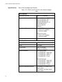
Specifications
Table 6 lists the specifications of the AT-2700FTX and AT-2701FTX
Series adapter cards.
Table 6. AT-2700FTX and AT-2701FTX Series Network Adapter
Cards
Basic Features
Supported Platforms
IBM PC or compatible
Supported Operating Systems
Microsoft Windows 2000
Microsoft Windows 2003
Microsoft Windows XP
Microsoft Windows NT 4.0
Novell Netware 6.5
Linux 2.4 and 2.6
Solaris 9
Type of Motherboard Connector
AT-2700FTX Series:
PCI bus 2.1-compliant
(32-bit bus width)
AT-2701FTX Series:
PCI bus 2.2-compliant
(32-bit bus width)
Number of Ports
2
Twisted Pair Port
Standards
10Base-T and 100Base-TX
Speed
10 Mbps or 100 Mbps
(Default: Auto-Negotiation)
Duplex Mode
Half- or full-duplex
(Default: Auto-Negotiation)
Type of Connector
RJ-45
Maximum Operating Distance
100 m (328 ft.)
Type of Cabling
10Base-T operation:
100 Ohm shielded or
unshielded Category 3 or better
100Base-TX operation:
100 Ohm shielded or
unshielded Category 5 or better
Fiber Optic Port
26
Standard
100Base-FX
Speed
100 Mbps
Network Adapter Card Installation Guide
Table 6. AT-2700FTX and AT-2701FTX Series Network Adapter
Cards (Continued)
Duplex Mode
Half- or full-duplex
(Default: full-duplex)
Type of Connector
AT-2700FTX Series:
AT-2700FTX/SC - duplex SC
AT-2700FTX/ST - duplex ST
AT-2700FTX/MT - MT-RJ
AT-2700FTX/VF - VF-45
AT-2701FTX Series:
AT-2701FTX/SC - duplex SC
AT-2701FTX/ST - duplex ST
AT-2701FTX/MT - MT-RJ
AT-2701FTX/VF - VF-45
Maximum Operating Distance1
2 km (1.24 miles) in full-duplex
mode
412 m (1373 feet) in half-duplex
mode
Type of Cabling
50/125 or 62.5/125 micron (core/
cladding) multimode fiber optic
cable
Operating Specifications
Wavelength: 1310 nm
Output power - 50/125 micron
cabling:
Minimum: -22.5 dBm
Maximum: -14 dBm
Output power - 62.5/125 micron
cabling:
Minimum: -19.0 dBm
Maximum: -14 dBm
Input sensitivity:
Minimum: -31 dBm
Maximum: -14 dBm
Wake on LAN Feature
AT-2700FTX Series
Supported on both ports.
AT-2701FTX Series
Supported on both ports.
Default Setting
Disabled
27
Chapter 1: Network Adapter Card Overview
Table 6. AT-2700FTX and AT-2701FTX Series Network Adapter
Cards (Continued)
BootPROM Chip and MBA Feature
AT-2700FTX Series
Optional
AT-2701FTX Series
Standard
Default Port
100Base-FX
Load Balancing and Fail-over Protection
AT-2700FTX Series
Not supported
AT-2701FTX Series
Supported2
Default setting: Disabled
1. Numerous factors, such as too many splices or poorly implemented splices,
can significantly reduce the maximum distance of a fiber optic port. Fiber optic
cable should only be installed by a qualified fiber optic cable contractor.
2. Microsoft Windows 2000, 2003, and XP.
LEDs
Table 7 describes the LEDs on the AT-2700FTX and AT-2701FTX Series
adapter cards. The twisted pair port uses either the 10 or 100 LED,
depending on its operating speed. The fiber optic port uses just the 100
LED.
Table 7. AT-2700FTX and AT-2701FTX Series LEDs
LED
10
28
Status
Description
Green
The twisted pair port
is operating at 10
Mbps, full-duplex
mode.
Amber
The twisted pair port
is operating at 10
Mbps, half-duplex
mode.
Flashing
The twisted pair port
is receiving or
transmitting network
packets at 10 Mbps.
Network Adapter Card Installation Guide
Table 7. AT-2700FTX and AT-2701FTX Series LEDs (Continued)
LED
100
Status
Description
Green
The twisted pair port
or fiber optic port is
operating at 100
Mbps, full-duplex
mode.
Amber
The twisted pair port
or fiber optic port is
operating at 100
Mbps, half-duplex
mode.
Flashing
The twisted pair port
or fiber optic port is
receiving or
transmitting network
packets at 100 Mbps.
29
Chapter 1: Network Adapter Card Overview
AT-2745FX and AT-2746FX Series
The adapters in the AT-2745FX Series are:
AT-2745FX/SC
AT-2745FX/ST
AT-2745FX/STSC
The adapters in the AT-2746FX Series are:
AT-2746FX/SC/SC
AT-2746FX/ST/ST
AT-2746FX/ST/SC
The AT-2745FX and AT-2746FX Series are dual port adapters. But unlike
the other dual port adapters discussed in this guide, which feature a
twisted pair port and a fiber optic port, these adapter cards have two fiber
optic ports. One port is 10Base-FL and the other 100Base-FX. These
adapters allow you to use the same network adapter card for either 10
Mbps or 100 Mbps over fiber optic cable. The cards are appropriate in
network environments whether there is a mix of 10Base-FL and 100BaseFX Ethernet hubs and switches. They can also be useful in 10Base-FL
environments where there are future plans to upgrade the switches and
hubs to 100Base-FX.
Note
You can use only one port on this adapter at a time. Do not attach
both ports to the network at the same time.
Differences between the two series are:
30
The AT-2745FX Series is PCI 2.1-compliant.
The AT-2746FX Series is PCI 2.2-compliant.
The AT-2745FX Series was offered in two versions — a standard
version and a low profile version for systems that accept only low
profile adapters.
The AT-2746FX Series can be installed in either a standard or low
profile system. The adapter comes with two brackets, one for a
standard system and another for a low profile system.
The AT-2745FX Series supported the Wake on LAN feature only on
the 100Base-FX port.
The AT-2746FX Series supports the Wake on LAN feature on both
ports.
Network Adapter Card Installation Guide
Specifications
The BootPROM chip and MBA were optional with the AT-2745FX
Series.
The BootPROM chip and MBA come standard with the AT-2746FX
Series.
Table 8 lists the specifications of the AT-2745FX and AT-2746FX Series
adapter cards.
Table 8. AT-2745FX and AT-2746FX Series Network Adapter
Cards
Basic Features
Supported Platforms
IBM PC or compatible
Supported Operating Systems
Microsoft Windows 2000
Microsoft Windows 2003
Microsoft Windows XP
Microsoft Windows NT 4.0
Novell Netware 6.5
Linux 2.4 and 2.6
Solaris 9
Type of Motherboard Connector
AT-2745FX Series:
PCI bus 2.1-compliant
(32-bit bus width)
AT-2746FX Series:
PCI bus 2.2-compliant
(32-bit bus width)
Number of Ports
2
10Base-FL Fiber Optic Port
Standard
10Base-FL
Speed
10 Mbps
Duplex Mode
Half- or full-duplex
(Default: full-duplex)
Type of Connector
AT-2745FX Series:
AT-2745FX/SC: duplex SC
AT-2745FX/ST: duplex ST
AT-2745FX/STSC: duplex ST
AT-2746FX Series:
AT-2746FX/SC/SC: duplex SC
AT-2746FX/ST/ST: duplex ST
AT-2745FX/ST/SC: duplex ST
Maximum Operating Distance1
2 kilometers (1.2 miles)
31
Chapter 1: Network Adapter Card Overview
Table 8. AT-2745FX and AT-2746FX Series Network Adapter
Cards (Continued)
Type of Cabling
50/125 or 62.5/125 micron (core/
cladding) multimode fiber optic
cable
Operating Specifications
Wavelength: 820 nm
Output power - 50/125 micron
cabling:
Minimum: -18.8 dBm
Maximum: -13.8 dBm
Output power - 62.5/125 micron
cabling:
Minimum: -15.0 dBm
Maximum: -10.0 dBm
Input sensitivity:
Typical: -4.4 dBm
100Base-FX Fiber Optic Port
Standard
100Base-FX
Speed
100 Mbps
Duplex Mode
Half- or full-duplex
(Default: full-duplex)
Type of Connector
AT-2745FX Series:
AT-2745FX/SC: duplex SC
AT-2745FX/ST: duplex ST
AT-2745FX/STSC: duplex SC
AT-2746FX Series:
AT-2746FX/SC/SC: duplex SC
AT-2746FX/ST/ST: duplex ST
AT-2745FX/ST/SC: duplex SC
32
Maximum Operating Distance1
2 kilometers (1.2 miles) in fullduplex mode
412 m (1373 feet) in half-duplex
mode
Type of Cabling
50/125 or 62.5/125 micron (core/
cladding) multimode fiber optic
cable
Network Adapter Card Installation Guide
Table 8. AT-2745FX and AT-2746FX Series Network Adapter
Cards (Continued)
Operating Specifications
Wavelength: 1310 nm
Output power - 50/125 micron
cabling:
Minimum: -22.5 dBm
Maximum: -14 dBm
Output power - 62.5/125 micron
cabling:
Minimum: -19.0 dBm
Maximum: -14 dBm
Input sensitivity:
Minimum: -31 dBm
Maximum: -14 dBm
Wake on LAN Feature
AT-2745FX Series
Supported on 100Base-FX port
only.
AT-2746FX Series
Supported on both ports.
Default Setting
Disabled
BootPROM Chip and MBA Feature
AT-2745FX Series
Optional
AT-2746FX Series
Standard
Default Port
100Base-FX
Load Balancing and Fail-over Protection
AT-2745FX Series
Not supported
AT-2746FX Series
Supported2
Default setting: Disabled
1. Numerous factors, such as too many splices or poorly implemented splices,
can significantly reduce the maximum distance of a fiber optic port. Fiber optic
cable should only be installed by a qualified fiber optic cable contractor.
2. Microsoft Windows 2000, 2003, and XP.
33
Chapter 1: Network Adapter Card Overview
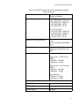
LEDs
Table 9 describes the LEDs on the AT-2745FX and AT-2746FX Series
adapter cards. The 10Base-FL port uses the 10 LED and the 100Base-FX
port uses the 100 LED.
Table 9. AT-2745FX and AT-2746FX Series LEDs
LED
10
100
34
Status
Description
Green
The 10Base-FL port
is operating at 10
Mbps, full-duplex
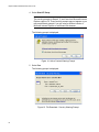
mode.
Amber
The 10Base-FL port
is operating at 10
Mbps, half-duplex
mode.
Flashing
The 10Base-FL port
is receiving or
transmitting network
packets at 10 Mbps.
Green
The 100Base-FX port
is operating at 100
Mbps, full-duplex
mode.
Amber
The 100Base-FX port
is operating at 100
Mbps, half-duplex
mode.
Flashing
The 100Base-FX port
is receiving or
transmitting network
packets at 100 Mbps.
Network Adapter Card Installation Guide
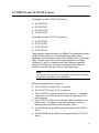
Additional Features
The following sections describe these network adapter card features:
❑ “Wake on LAN” on page 35
❑ “Driver Installation and the AT-Setup Utility” on page 36
❑ “Virtual LANs and the AT-MUX Protocol” on page 37
❑ “Operating Statistics and the AT-Stat Utility” on page 38
❑ “Diagnostics and the AT-Diag Utility” on page 39
❑ “Load Balancing and Fail-over Protection” on page 39
❑ “Managed Boot Agent” on page 43
Wake on LAN
This feature can help automate many of your network administrator
functions, such as backing up workstation files and updating system files.
It allows a network adapter card to power ON a system that has been
powered OFF or is in a sleep mode.
The feature is activated whenever the network adapter card receives a
special signal, called a Magic Packet, from a network management
program. Once the card has received the Magic Packet and instructed the
system to power ON, the network management program can run whatever
network management function needs to be performed on the system,
automatically. If your network management program permits, you can
configure the program to run the tasks during non-business hours so as
not interrupt the work of the network users. This helps simplify your
network maintenance tasks and limits the impact the tasks have on your
network users.
There are several steps you need to perform before you can use the Wake
on LAN feature on the network adapter card. First, you need to determine
whether the system where you will be installing the card supports Wake on
LAN. Not all do. The best way to determine this is by referring to the
system’s documentation.
Next, you need to determine whether the system is PCI 2.1- or PCI 2.2compliant. (PCI is an acronym for Peripheral Component Interconnect.)
Again, the system’s documentation should tell you this. Computers that
are PCI 2.1-compliant and that support Wake on LAN control the feature
through a special Wake on LAN connector on the system’s motherboard.
As part of the installation procedure you will need to connect the network
adapter card to the special connector on the motherboard using the Wake
on LAN cable included with the adapter card.
35
Chapter 1: Network Adapter Card Overview
When you install a PCI 2.2-compatible adapter in a PCI 2.2-compliant
computer, the Wake on LAN cable is unnecessary because the feature is
controlled through the connector bus on the network adapter card and the
system’s motherboard.
Note
Wake on LAN is not supported when a PCI 2.1-compliant adapter,
such as the AT-2450FTX Series, is installed in a PCI 2.2-compliant
computer. Additionally, Wake on LAN is not supported on the
10Base-FL ports on the AT-2450FTX and AT-2745FX Series
network adapter cards.
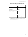
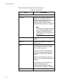
The following table can help sort things out. To determine whether you
need to use the Wake on LAN cable, match the type of adapter you
purchased with the type of system in which you are installing it.
Table 10. When to Use the Wake on LAN Cable
PCI 2.1-Compatible
System
PCI 2-2 Compatible
System
PCI 2.1-compatible
adapter
Install Wake on LAN
cable
Wake on LAN not
supported.
PCI 2.2 compatible
adapter
Install Wake on LAN
cable
Connector bus
(Wake on LAN cable
not used)
This feature also requires a network management program capable of
sending out Magic Packets to the network adapter card. An example is HP
OpenView Network Node Manager. Of course, whatever program you
choose to use should also allow you to specify what network maintenance
functions you want performed once a system has powered ON.
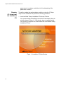
Driver
Installation and
the AT-Setup
Utility
The quickest and easiest way to install the driver for the network adapter
card on a Microsoft Windows 2000, 2003, or XP system is with the
AT-Setup utility. This utility, included on the Allied Telesyn Installation CD,
is also useful in updating an adapter driver already installed on a system
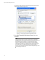
or correcting a driver installation. For systems without a CD driver, the
Installation CD comes with a utility program that creates a driver
installation diskette that contains the AT-Setup utility and the driver, so
you can run the program from a diskette drive rather than from a CD drive.
For instructions on how to use the AT-Setup utility, refer to Chapter 3,
“Microsoft Windows 2000, 2003, and XP” on page 57.
36
Network Adapter Card Installation Guide
Note
The Installation CD that comes with your network adapter card has
two drivers for Microsoft Windows 2000, 2003, or XP system. There
is a regular driver and an enhanced driver that supports load
balancing and fail-over (LBFO) protection. The AT-Setup utility can
be used to install the regular driver. To install the LBFO driver, you
must install it manually. For further information, refer to “Load
Balancing and Fail-over Protection” on page 39 and “Choosing a
Network Adapter Card Driver” on page 58.
Virtual LANs and
the AT-MUX
Protocol
All of the adapters discussed in this guide are IEEE 802.1Q-compliant and
are designed to support virtual LANs (VLANs) and tagged packets. A
VLAN is an independent traffic domain where traffic generated by the
nodes of a VLAN is restricted only to nodes that are members of the same
VLAN. Traffic within a VLAN cannot cross over a VLAN boundary unless
there is an interconnection device, such as a router or a Layer 3 switch, in
the network.
VLANs are often used to group nodes with related functions into their own
separate, logical LAN segments. These VLAN groupings can be based on
similar data needs or security requirements. VLANs can increase network
performance and security by restricting traffic to specific devices or areas
of a network.
A tagged VLAN (IEEE 802.1Q) contains one or more network links that
carry traffic from more than one VLAN. The VLAN traffic is identified by a
header tag, or simply tag, that follows the source and destination
addresses in a packet. The tag contains a VLAN identifier (VID) that
uniquely identifies the VLAN to which a packet belongs.
The Allied Telesyn network adapter cards are capable of reading the
header tag in tagged packets as they arrive on the port, as well as adding
tags to packets when transmitting packets.
Before a network adapter card can handle tagged packets, you must
configure it by specifying the appropriate VIDs of the VLANs whose tagged
packets the adapter is to process.
There are two ways to add VIDs to a network adapter card in a Microsoft
Windows 2000, 2003, or XP system. If the card will be handling tagged
traffic from only one tagged VLAN, you can specify the VID using the
Network Connections window in Microsoft Windows, as explained in
“Configuring Additional Network Adapter Card Settings” on page 96.
If the network adapter card will be handling tagged traffic from more than
one VLAN, you can use the AT-MUX protocol, which is included on the
Installation CD shipped with the network adapter card. The protocol allows
you to assign up to 16 VIDs to a single adapter, enabling a network
37
Chapter 1: Network Adapter Card Overview
adapter card to process tagged traffic from up to 16 different VLANs. The
protocol is described in Chapter 9, “AT-MUX Multiple VLAN Protocol” on
page 157.
Note
The AT-MUX protocol is compatible with Microsoft Windows 2000,
2003, and XP operating systems. You cannot use this protocol with
any other operating system.
The following briefly outlines the behavior of a network adapter card when
handling tagged and untagged VLAN traffic:
Operating
Statistics and the
AT-Stat Utility
An adapter where no VIDs have been assigned accepts and transmits
only untagged packets. (An untagged packet does not contain a
header tag and, consequently, lacks VLAN identification.) The adapter
discards any tagged packets that arrive on the port.
An adapter where at least one VID has been assigned accepts only
those tagged packets with header tags that match the assigned VIDs.
The adapter discards all untagged packets as well as any tagged
packets with VIDs that do not match the VIDs assigned to the card.
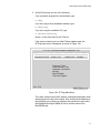
The AT-Stat utility can used to configure a card’s operating specifications
and display operating statistics. Functions include:
Displaying performance statistics, such as the number of packets sent
and received by a network adapter card.
Displaying the number of packet errors, such as CRC errors and
alignment errors.
Configuring the IP address, subnet mask, and gateway address.
Pinging another network device.
Performing a throughput test.
For instructions, refer to Chapter 8, “AT-Stat Utility” on page 133.
Note
The AT-Stat utility is compatible with Microsoft Windows 2000,
2003, and XP operating systems. This utility cannot be used with
any other operating system.
38
Network Adapter Card Installation Guide
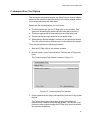
Diagnostics and
the AT-Diag
Utility
Included on the Allied Telesyn Installation CD is the AT-Diag utility. This
program is useful in testing and configuring a network adapter card.
Functions include:
Testing a network adapter card.
Performing a link test between an adapter port and a remote device,
such as an Ethernet switch or hub.
Setting the speed and duplex mode of an adapter port.
Enabling or disabling the BootPROM chip and MBA.
Specifying the default port for MBA.
Viewing hardware information.
For instructions, refer to Chapter 10, “AT-Diag Utility” on page 175.
Load Balancing
and Fail-over
Protection
Allied Telesyn offers two drivers for an adapter card installed in a Microsoft
Windows 2000, 2003, or XP system. There is a regular driver and an
enhanced driver with load balancing and fail-over (LBFO) protection.
These latter features are described in the following subsections.
Load Balancing
The load balancing feature of the LBFO driver is primarily intended for
adapters in network servers. It enhances network performance by
distributing the traffic over two adapters and also increases network
resiliency by providing a redundant link from the server to the network
should a link fail.
The LBFO driver allows you to increase the bandwidth from a network
server by configuring two network adapters to function as one virtual
adapter. The two adapters distribute traffic between themselves by taking
turns transmitting packets in a round-robin fashion. One adapter transmits
a packet, the next packet is transmitted by the other adapter, and so on.
Note the following before using the LBFO driver:
This driver is supported only on Microsoft Windows 2000, 2003, and
XP systems.
The driver is supported on the AT-2451FTX, AT-2701FX, AT-2701FTX,
and AT-2746FX Series cards. It is not supported on the older versions
of these adapters (for example, AT-2450FTX, AT-2700FX, etc.).
Note
The LBFO driver has not been certified by Microsoft Corporation.
39
Chapter 1: Network Adapter Card Overview
There are two versions of the load balancing feature: mode 1 and mode 2.
The basic characteristics of mode 1 are:
Both adapters use the same MAC address, but different IP addresses.
The ports on the two adapter cards must be connected to the same
remote device.
The basic characteristics of mode 2 are:
Both adapters use different MAC addresses and IP addresses.
The ports on the two adapter cards can be connected to the same
remote device or to different remote devices.
While Mode 1 typically offers the best in terms of performance, you might
not be able to use it in all situations. It all depends on the capability of the
Ethernet switch to which the ports on the adapters are connected. If the
switch cannot handle learning the same MAC address on more than one
port, you will probably need to use Mode 2.
Here are the steps to implementing load balancing:
1. Install two adapter cards into the system. The two cards must be
identical (for example, two AT-2701FX Series cards).
2. Manually load the LBFO driver onto the cards. Be sure to install the
LBFO driver instead of the regular driver. You must install the driver
twice, once for each card. For instructions, refer to “Manually Installing
a Driver” on page 73.
Note
You cannot use the AT-Setup utility to load the LBFO driver.
3. Manually assign both cards an IP address or activate the DHCP client.
The IP addresses must be different for the two cards, even if you are
using mode 1. The addresses must belong to the same subnet.
Consequently, the network portion of the addresses must be the same
as well as the subnet masks. For instructions, refer to “Configuring the
IP Address, Subnet Mask, and Gateway Address” on page 92. (In
mode 1, both adapters use the same MAC address. The MAC address
assignment is handled automatically by the driver.)
4. Assign both adapter cards to the same team. For instructions, refer to
“Configuring Additional Network Adapter Card Settings” on page 96.
40
Network Adapter Card Installation Guide
Fail-over Protection
Another feature of the LBFO driver is fail-over protection. This feature is
useful in situations where a network device could benefit from link
redundancy, but not necessarily load balancing. The fail-over feature
protects against a loss of network connectivity should an adapter lose its
link to a remote device or the remote device loses power or is taken out of
service, such as for maintenance. When the link is lost on the primary
adapter, the redundant adapter automatically takes over the task of
sending and receiving network traffic.
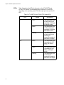
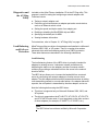
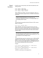
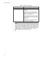
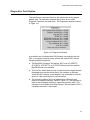
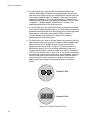
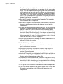
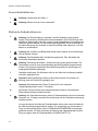
There are two possible configurations for this feature. In the first
configuration both the primary link and the redundant link are connected to
the same remote node. This is illustrated in Figure 1 where the links from a
server containing two network adapter cards both go to the same Ethernet
switch. If the primary link should fail, the redundant link automatically takes
over, preventing a loss of network connectivity to the server.
Primary
Link
Redundant
Link
Figure 1. Fail-over Protection - Configuration #1
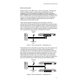
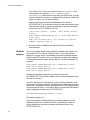
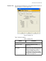
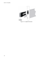
The drawback to this configuration is that it does not protect against a loss
of network access to the server should the switch lose power or be
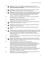
removed from service. Fortunately, with fail-over protection the links can
go to different remote nodes. An example is illustrated in Figure 2 where
the primary and redundant links of the two adapters in the server go to
different Ethernet switches. Now, if the switch where the primary link is
connected loses power or is removed from service, network connectivity to
the server continues uninterrupted through the other Ethernet switch.
Primary
Link
Redundant
Link
Figure 2. Fail-over Protection - Configuration #2
41
Chapter 1: Network Adapter Card Overview
The selection of the active adapter is determined by the network driver
and the computer’s operating system. The active, primary adapter is
determined by whichever adapter establishes a link with its remote device
first. If the primary adapter loses its link with its remote device, the
redundant adapter automatically changes to the primary function and
remains as the primary adapter until such time as the status of its link
changes.
When an adapter card driver notes that it has changed from the redundant
to the active status, it sends out a Address Resolution Protocol (ARP)
packet. The purpose of the packet is to notify the network nodes of the
system’s new MAC address and IP address.
To implement this feature, you need to install two identical adapters into
the system and create a team of the cards. Both adapters must be
members of the same team. One adapter will function as the active,
primary adapter and the second adapter will function as the redundant
adapter. There can be only one active and one redundant adapter per
team. You must also assign each adapter a unique IP address.
Implementing port redundancy requires the following steps:
1. Install two identical adapters in the network device.
2. Manually load the LBFO driver onto the cards. Be sure to install the
LBFO driver instead of the regular driver. You must install the driver
twice, once for each card. For instructions, refer to “Manually Installing
a Driver” on page 73.
Note
You cannot use the AT-Setup utility to load the LBFO driver.
3. Assign each adapter a unique IP address. The IP addresses must be
in the same subnet. Consequently, the network portion of the
addresses must be the same as well as the subnet masks. For
instructions, refer to “Configuring the IP Address, Subnet Mask, and
Gateway Address” on page 92.
4. Create a team consisting of the two adapter cards. For instructions,
refer to “Configuring Additional Network Adapter Card Settings” on
page 96.
42
Network Adapter Card Installation Guide
Managed Boot
Agent
The managed boot agent (MBA) and the BootPROM chip allow you to
perform pre-boot procedures on a system, such as installing an operating
system, running a virus checker, or downloading a predefined system
configuration. You can couple this feature with the Wake on LAN feature to
perform configuration and maintenance tasks during non-work hours so as
not to interfere with the work of your network users.
Note
The MBA and BootPROM chip come standard with the AT-2451FTX,
AT-2701FX, AT-2701FTX, and AT-2746FX Series cards. They are
sold separately for the AT-2450FTX, AT-2700FX, AT-2700FTX, and
AT-2745FX Series adapters.
In order to use MBA on a dual port card you must specify which port is
connected to the network. This is made with the AT-Diag utility, described
in Chapter 10 on page 175. The MBA can address only one port at a time
and it cannot change ports automatically. The selected port is referred to
as the default MBA port. The factory settings of the default MBA port on
the dual port adapter cards are:
AT-2450FTX and AT-2451FTX Series cards — 10/100Base-TX twisted
pair port
AT-2700FTX and AT-2701FTX Series cards — 100Base-FX fiber optic
port
AT-2745FX and AT-2746FX Series cards — 100Base-FX fiber optic
port
For example, to use MBA on the 10Base-FL port on the AT-2746FX Series
card, you would run the AT-Diag utility and specify that port as the default
MBA port.
43
Chapter 1: Network Adapter Card Overview
44
Chapter 2
Installing a Network Adapter Card
This chapter contains instructions for installing an Allied Telesyn network
adapter card. Sections in the chapter include:
“Verifying Package Contents” on page 46
“Reviewing Safety Precautions” on page 47
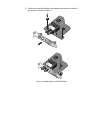
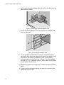
“Installing the Low Profile Bracket” on page 48
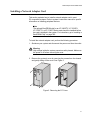
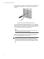
“Installing a Network Adapter Card” on page 51
45
Chapter 2: Installing a Network Adapter Card
Verifying Package Contents
Make sure the following items are included in your package. If any item is
missing or damaged, contact your Allied Telesyn sales representative for
assistance.
❑ Allied Telesyn Network Adapter Card
❑ Allied Telesyn Installation CD
❑ Wake on LAN Cable
❑ Low Profile Bracket (AT-2451FTX, AT-2701FX, AT-2701FTX, and
AT-2746FX Series)
❑ Warranty Card
46
Network Adapter Card Installation Guide
Reviewing Safety Precautions
Please review the following safety precautions before you begin to install
the network adapter card. Refer to Appendix E, “Translated Safety
Statements” on page 209 for translated safety statements in your
language.
Warning
This is a “Class 1 LED product”. 1
Warning
Do not stare into the laser beam. 2
Warning
Warning: Do not look directly at the fiber optic cable ends or inspect
the cable ends with an optical lens. 31
Warning
Do not work on this equipment or cables during periods of lightning
activity. 4
Warning
Operating Temperature: This product is designed for a maximum
ambient temperature of 40 degrees C. 9
Note
All Countries: Install this product in accordance with local and
National Electric Codes. 10
47
Chapter 2: Installing a Network Adapter Card
Installing the Low Profile Bracket
The AT-2451FTX, AT-2701FX, AT-2701FTX and AT-2746FX Series
network adapter cards come with two brackets, a pre-installed standard
bracket and a low profile bracket for systems that require low profile
adapters. If you are installing the card in a low profile system, you must
replace the standard bracket on the card with the low profile bracket.
Replacing the bracket must be performed with extreme care to avoid
damaging the network adapter card.
Caution
Wear a grounding device and observe electrostatic discharge
precautions when installing the bracket. Failure to observe this
caution could result in damage to the network adapter card.
48
Network Adapter Card Installation Guide
To install the low profile bracket, perform the following procedure:
1. Using a Phillips-head screwdriver, carefully remove the two screws
that secure the standard bracket to the network adapter card and
remove the bracket, as shown in Figure 3.
TX
RX
TX
RX
10
0
TX
RX
TX
RX
10
0
Figure 3. Removing the Standard Bracket
49
2. Position the low profile bracket on the adapter card and secure with the
two screws, as shown in Figure 4.
TX
RX
TX
RX
10
0
TX
RX
TTXX
RRXX
11000
0
Figure 4. Installing the Low Profile Bracket
Network Adapter Card Installation Guide
Installing a Network Adapter Card
This section explains how to install a network adapter card in most
PC-compatible systems. Refer to system’s instruction manual for specific
information on installing peripheral devices.
Note
The optional BootPROM chip for an AT-2450FTX, AT-2700FX,
AT-2700FTX, or AT-2745FX Series card should be installed before
the card is installed in the system. For instructions, go to “Installing a
BootPROM Chip” on page 200.
To install the network adapter card, perform the following procedure:
1. Shutdown your system and disconnect the power cord from the outlet.
Warning
High voltage inside the system presents a safety hazard. Make sure
the power is off before removing the cover.
2. Remove the system’s cover by removing the screws from the chassis
and gently sliding off the cover. See Figure 5.
Figure 5. Removing the PC Cover
51
Chapter 2: Installing a Network Adapter Card
3. Select an empty, non-shared PCI slot and remove the faceplate. Keep
the faceplate in a safe place. You may need it for future use. See
Figure 6.
Figure 6. Removing the Faceplate From PCI Slot
If you are installing the network adapter card in a PCI 2.1-compliant
system and want to use the Wake on LAN feature, choose a slot that is
near the Wake on LAN connector on the system’s motherboard. This
will make installing the Wake on LAN cable easier.
Note
If you cannot locate or know how to find an PCI slot, refer to the
documentation that came with your system.
4. Remove the network adapter card from the shipping package and
store the packaging material in a safe location.
Caution
Wear a grounding device and observe electrostatic discharge
precautions when installing the network adapter card in a system.
Failure to observe this caution could result in damage to the card.
52
Network Adapter Card Installation Guide
5. To use the Wake on LAN feature in a PCI 2.1-compatible system,
connect one end of the Wake on LAN cable included with the network
adapter card to the Wake on LAN connector on the card, as shown in
Figure 7. If you are installing the card in a PCI 2.2-compliant system or
do not intend to use this feature, skip this step. For background
information on this feature, refer to “Wake on LAN” on page 35.
Figure 7. Connecting the Wake on LAN Cable to the Adapter Card
53
Chapter 2: Installing a Network Adapter Card
6. Gently insert the network adapter card into the PCI slot. Make sure the
card is securely seated.
Figure 8. Inserting the Network Adapter Card
7. Secure the network adapter card to the chassis with a Phillips-head
screw, not provided.
Figure 9. Securing the Adapter Card
8. To use the Wake on LAN feature in a PCI 2.1-compatible system,
connect the other end of the Wake on LAN cable to the Wake on LAN
connector on the system’s motherboard. Refer to the system’s
documentation for the location of the connector. If you are installing
the card in a PCI 2.2-compliant system or do not want to use the Wake
on LAN feature, skip this step.
9. Replace the system’s cover and secure it with the screws removed in
Step 2.
10. Connect the network adapter card to the network by connecting the
appropriate network cable.
54
Network Adapter Card Installation Guide
Note
If you installed a dual port network adapter card, connect only one
port to the network.
11. Power ON the system.
If you installed the adapter card in a Microsoft Windows 2000, 2003, or
XP system and did not pre-install the driver, the Found New Hardware
Wizard launches automatically once the system detects the new card.
Figure 10 illustrates the first window of the wizard.
Figure 10. Found New Hardware Wizard Window
12. At this point, you have a choice on how to install the adapter card’s
driver. If you prefer to use the AT-Setup utility, click Cancel in the
wizard and perform the procedure “Installing or Updating a Driver
Using the AT-Setup Utility” on page 59. Alternatively, you can use the
wizard to manually install the driver by performing the procedure
“Manually Installing a Driver” on page 73.
This completes the installation of the network adapter card. Go to the
appropriate chapter in this guide for installation instructions for the
adapter card’s driver.
55
Chapter 2: Installing a Network Adapter Card
56
Chapter 3
Microsoft Windows 2000, 2003, and XP
This chapter contains instructions on how to install, update, and remove
the network adapter driver on a Microsoft Windows 2000, 2003, or XP
system. This chapter also contains the procedure for adjusting a network
adapter card’s parameters, such as assigning an IP address and changing
port speed and duplex mode. Procedures in the chapter include:
“Choosing a Network Adapter Card Driver” on page 58
“Installing or Updating a Driver Using the AT-Setup Utility” on page 59
“Creating a Driver Installation Disk” on page 68
“Manually Installing a Driver” on page 73
“Manually Updating a Driver” on page 77
“Removing a Driver” on page 85
“Running AT-Setup to Complete Driver Installation” on page 90
“Configuring the Network Adapter Card Settings” on page 91
57
Chapter 3: Microsoft Windows 2000, 2003, and XP
Choosing a Network Adapter Card Driver
The first step to installing the driver for your new network adapter card is to
select a driver. Allied Telesyn offers two drivers for Microsoft Windows
2000, 2003, and XP systems. There is a regular driver and an enhanced
driver that features load balancing and fail-over (LBFO) protection. The
LBFO driver is primarily intended for adapters in network servers. It
enhances network performance by distributing the traffic from the server
over two adapters. It also increases the resiliency of your network by
providing a redundant link from the server to the network. For background
information on the LBFO driver, refer to “Load Balancing and Fail-over
Protection” on page 39.
You can install the regular driver using the AT-Setup utility, as explained in
“Installing or Updating a Driver Using the AT-Setup Utility” on page 59 or
manually with the procedure “Manually Installing a Driver” on page 73.
To install the LBFO driver, you must use the procedure “Manually
Installing a Driver” on page 73. The LBFO driver cannot be installed using
the AT-Setup utility.
Note
The LBFO driver has not been certified by Microsoft Corporation.
58
Network Adapter Card Installation Guide
Installing or Updating a Driver Using the AT-Setup Utility
Included on the Allied Telesyn Installation CD is the AT-Setup utility. This
utility is a quick and easy way to install the regular adapter driver on a
Microsoft Windows 2000, 2003, or XP system.
Note
Do not perform this procedure to install the LBFO driver. Instead, go
to “Manually Installing a Driver” on page 73.
You can run the AT-Setup utility either before or after you install the
network adapter card. Running the AT-Setup utility before installing the
card pre-loads the driver.
If you install an adapter card in your system before running the AT-Setup
utility, your operating system will attempt to install an adapter driver
automatically. Microsoft’s New Hardware Installation Wizard will prompt
you for the location of the appropriate driver for the adapter card. You can
either instruct the installation wizard to the proper location on the Allied
Telesyn Installation CD, given in Step 11 in the procedure “Manually
Installing a Driver” on page 73, or cancel the hardware wizard and perform
the AT-Setup utility.
You can also use the AT-Setup utility to update the regular driver or to
correct problems during installation. If an error message occurs, simply
run AT-Setup again. The utility will scan your operating system and fix any
known issues.
AT-Setup
Guidelines
Before running the AT-Setup utility, please review the following guidelines:
The AT-Setup utility is designed for Microsoft Windows 2000, 2003,
and XP operating systems. Do not use this program with any other
operating system.
If the system contains more than one adapter card, you must install the
adapter driver on each card. You can either run the AT-Setup utility,
which automatically installs the driver on all of the adapter cards that it
detects in the system, or you can install the driver manually for each
card.
If the system where you installed the adapter card does not have a CD
drive, you can create a driver installation diskette and run the AT-Setup
utility from the diskette. Refer to “Creating a Driver Installation Disk” on
page 68 for instructions.
Allied Telesyn network adapter cards are PCI-compliant. The adapter
card’s operating parameters, such as interrupt level and memory
range, are set automatically by the computer to avoid conflict with
other devices in your system. Do not change any of the operating
59
Chapter 3: Microsoft Windows 2000, 2003, and XP
parameters of an adapter card without a full understanding of the
parameters’ functions.
Running
AT-Setup from
the Installation
CD
To install or update the regular adapter card driver using the AT-Setup
utility from the Installation CD, perform the following procedure:
1. Insert the Allied Telesyn Installation CD into the CD drive.
Your system should automatically launch the CD and display the main
window, shown in Figure 11. If this window does not appear, doubleclick on the My Computer icon, then double-click on the Allied Telesyn
Installation CD icon.
Figure 11. Installation CD Main Window
60
Network Adapter Card Installation Guide
2. Select Tools.
The Tools window is shown in Figure 12.
Figure 12. Tools Window
3. Select AT-Setup Utility.
The AT-Setup Utility window is shown in Figure 13.
Figure 13. AT-Setup Utility Window
61
Chapter 3: Microsoft Windows 2000, 2003, and XP
4. Select Start AT-Setup.
Note
The security prompts in Steps 4, 5, and 6 are from Microsoft Internet
Explorer version 6.0. These security prompts may not appear or you
may see different prompts if you are using a different version of
Microsoft Internet Explorer or a different web browser.
The following prompt is displayed.
Figure 14. Active Content Warning Prompt
5. Select Yes.
The following prompt is displayed:
Figure 15. File Download - Security Warning Prompt
62
Network Adapter Card Installation Guide
6. Select Run to run the AT-Setup utility from the Installation CD.
The following security warning prompt is displayed.
Figure 16. Internet Explorer - Security Warning Prompt
7. Select Run to launch the AT-Setup utility.
If you are updating a driver, the program displays the Overwrite
Protection window, shown in Figure 17.
Figure 17. Overwrite Protection Window
63
Chapter 3: Microsoft Windows 2000, 2003, and XP
8. If the Overwrite Protection window appears, select Yes to All. The
utility searches the system for any network adapter cards. If it detects
a card(s), the utility displays the card model name(s) in the ATSetup
window. (In some cases, the utility might omit the model name and
display just the words “Ethernet Controller.”) An example of the
window is shown in Figure 18.
Figure 18. AT-Setup Window (Card Installed)
If the adapter card has not been installed, the window in Figure 19 is
displayed:
Figure 19. AT-Setup Window (No Card Installed)
64
Network Adapter Card Installation Guide
9. Select OK.
The AT-Setup utility copies the adapter driver from the Installation CD
to the system’s hard disk and integrates it with the system’s operating
system. The entire process can take up to 30 seconds to complete.
Note
If you see the error message “Failed to remove network adapter for
update. The data is invalid.”, click OK. The message can be ignored.
10. If the card is already installed in the system, the AT-Setup utility
displays the message in Figure 20 once the driver is installed. Click
OK. To complete the installation, connect the twisted pair cable or the
fiber optic cable to the port on the adapter.
Figure 20. AT-Setup Window - Completion
Note
To configure the adapter’s settings, refer to “Configuring the
Network Adapter Card Settings” on page 91.
65
Chapter 3: Microsoft Windows 2000, 2003, and XP
11. If the card has not been installed, the prompt in Figure 21 is displayed.
Remove the CD from the CD driver and click Yes. The Windows
operating system and the system are automatically shut down. You
can now install the adapter card. For instructions, refer to Chapter 2,
“Installing a Network Adapter Card” on page 45.
Figure 21. Shut Down Prompt
Running
AT-Setup from a
Driver
Installation
Diskette
To install the network adapter driver using the AT-Setup utility from a
driver installation diskette, perform the following procedure:
1. Insert the driver installation disk into the floppy drive.
Note
For instructions on how to create a driver installation disk, refer to
“Creating a Driver Installation Disk” on page 68.
2. From the Start menu on the Window’s toolbar, select Run, as shown in
Figure 22.
Figure 22. Run Selection in the Start Menu
66
Network Adapter Card Installation Guide
The Run window is shown in Figure 23.
Figure 23. Run Window
3. In the Open field, type: x:\Win_XP_200X\atsetup where ‘x’ is the drive
letter of the floppy drive.
4. Select OK.
5. To complete the installation of the adapter card driver, perform Steps 8
to 11 in the procedure “Running AT-Setup from the Installation CD” on
page 60.
67
Chapter 3: Microsoft Windows 2000, 2003, and XP
Creating a Driver Installation Disk
This procedure creates a driver installation diskette. You can use the
diskette to run the AT-Setup utility on those systems that do not have a CD
drive.
To create a driver installation disk, perform the following procedure on a
system that has both a CD drive and floppy drive:
1. Make sure your system is turned ON and the Windows operating
system is running.
2. Insert the Allied Telesyn Installation CD into the CD drive.
The Installation CD main window is shown in Figure 24. If this window
does not appear, double-click on the My Computer icon, then doubleclick on the Allied Telesyn Installation CD icon.
Figure 24. Allied Telesyn Installation CD Main Window
68
Network Adapter Card Installation Guide
3. Select Tools.
The Tools window is shown in Figure 25.
Figure 25. Installation CD Tools Window
4. Select Driver Installation Diskette.
The Driver Installation Diskette window is shown in Figure 26.
Figure 26. Driver Diskette Utility Window
69
Chapter 3: Microsoft Windows 2000, 2003, and XP
5. Insert a blank, formatted floppy disk into the floppy drive.
6. Select Create driver diskette.
Note
The security prompts in Steps 4, 5, and 6 are from Microsoft Internet
Explorer version 6.0. These security prompts may not appear or you
may see different prompts if you are using a different version of
Microsoft Internet Explorer or a different web browser.
The prompt in Figure 27 is displayed.
Figure 27. Active Content Warning Prompt
7. Select Yes.
The prompt in Figure 28 is displayed.
Figure 28. File Download - Security Warning Prompt
70
Network Adapter Card Installation Guide
8. Select Run to run the utility from the Installation CD.
The following security warning prompt is displayed.
Figure 29. Internet Explorer - Security Warning Prompt
9. Select Run.
The prompt in Figure 30 is displayed.
Figure 30. InstallShield Wizard
71
Chapter 3: Microsoft Windows 2000, 2003, and XP
10. Specify the floppy drive containing the blank disk.
11. Select Next. The adapter drivers and the AT-Setup utility are saved to
the floppy disk. The program displays the message in Figure 31when
the process is complete.
Figure 31. Driver Installation Diskette Completion Message
This completes the procedure for creating a driver installation disk. To
use the diskette to install the driver on a Microsoft Windows 2000,
2003, or XP system, refer to “Running AT-Setup from a Driver
Installation Diskette” on page 66 or “Manually Installing a Driver” on
page 73.
72
Network Adapter Card Installation Guide
Manually Installing a Driver
This section contains the procedure for manually installing the regular or
LBFO network adapter driver on a Microsoft Windows 2000, 2003, or XP
operating system. You can perform the procedure using the Allied Telesyn
Installation CD or, for those systems without a CD drive, a driver
installation diskette. For instructions on how to create a driver installation
diskette, refer to “Creating a Driver Installation Disk” on page 68.
1. Shutdown the Microsoft Windows 2000, 2003, or XP operating system
and power OFF your computer.
2. Install the network adapter card. Refer to Chapter 2, “Installing a
Network Adapter Card” on page 45 and the documentation that came
with your computer for instructions.
3. Power ON the computer.
After detecting the new adapter card, the system launches the Found
New Hardware Wizard, which displays the window shown in Figure 32.
Figure 32. Found New Hardware Wizard Window (1 of 4)
73
Chapter 3: Microsoft Windows 2000, 2003, and XP
4. Insert the Installation CD or the driver installation diskette into the
appropriate drive on the system.
Note
If you system launches the web browser when you insert the
Installation CD, minimize or close the web browser window.
5. In the Found New Hardware Wizard window, select No, not this time.
6. Select Next.
The window shown in Figure 33 is displayed.
Figure 33. Found New Hardware Wizard Window (2 of 4)
7. Select Install from a list or specific location (Advanced).
74
Network Adapter Card Installation Guide
8. Select Next.
The window shown in Figure 34 is displayed.
Figure 34. Found New Hardware Wizard Window (3 of 4)
9. If selected, deselect Search removable media (floppy, CD-ROM...).
10. Select Include this location in the search.
11. Specify the location of the driver file using the Browse button or by
entering the drive letter and path in the field.
If you are installing the regular driver, the driver files are stored in
this subdirectory on the Installation CD and the driver installation
diskette:
x:\drivers\Win_XP_200x
If you are installing the LBFO adapter driver, the files are stored in
this subdirectory on the Installation CD and the driver installation
diskette:
x:\drivers\Win_XP_200X_lbfo
Where X: is the driver letter of the CD drive or the diskette drive.
12. After you have specified the location, select Next.
75
Chapter 3: Microsoft Windows 2000, 2003, and XP
13. If you are installing the LBFO driver, a message is displayed stating
that the driver has not been certified by Microsoft. If you see the
message, click Continue Anyway.
The wizard installs the adapter driver. The installation process can
take up to 30 seconds to complete.
Once installed, the window in Figure 35 is displayed.
Figure 35. Found New Hardware Wizard Window (4 of 4)
14. Select Finish.
15. Reboot your system.
This completes the procedure for manually installing the driver on a
Microsoft Windows 2000, 2003, or XP system. To adjust the adapter’s
parameters, refer to “Configuring the Network Adapter Card Settings”
on page 91.
76
Network Adapter Card Installation Guide
Manually Updating a Driver
This section contains the procedure for updating a regular or LBFO
network adapter driver on a Microsoft Windows 2000, 2003, or XP system.
You can perform the procedure using the Allied Telesyn Installation CD or,
if the system does not have a CD driver, a driver installation disk. For
instructions on how to create a driver installation disk, refer to “Creating a
Driver Installation Disk” on page 68.
Note
Since the regular adapter driver and LBFO driver are considered
different drivers, you cannot use this procedure to convert a regular
driver already installed on a system into an LBFO driver, or vice
versa. If one of the adapter drivers is already installed, you must
uninstall it prior to installing the other driver. For background
information on the two drivers, refer to “Load Balancing and Failover Protection” on page 39 and “Choosing a Network Adapter Card
Driver” on page 58.
Note
You should have the Windows Installation CD or floppy disk(s)
available. You may be prompted to copy support files for networking.
To update a driver, perform the following procedure:
1. From the desktop, right-click the My Computer icon and select
Properties from the menu, as shown in Figure 36.
Figure 36. My Computer Icon and Menu
77
Chapter 3: Microsoft Windows 2000, 2003, and XP
The System Properties window is shown in Figure 37.
Figure 37. System Properties Window
78
Network Adapter Card Installation Guide
2. Select the Hardware tab.
The Hardware tab is shown in Figure 38.
Figure 38. Device Manager Tab Window
79
Chapter 3: Microsoft Windows 2000, 2003, and XP
3. Click the Device Manager button.
The Device Manager window is shown in Figure 39.
Figure 39. Device Manager Window
4. Expand Network adapters by either double-clicking on it or by clicking
once on the expansion box next to it.
The network adapter cards installed on the system are listed under
Network adapters. An example is shown here.
Note
The branch under Network Adapters will include VLANs if VIDs were
added to the adapter with the AT-MUX protocol. The VLANs are
labelled as “Allied Telesyn VLAN-Tagging miniport Driver.” In the
next step you must choose the selection for the network adapter
card and not a VLAN. The adapter card selection has the adapter’s
model number in the label.
80
Network Adapter Card Installation Guide
5. Right-click on the network adapter card whose driver you want to
update and select Update Driver from the pop-up menu, as shown
in.Figure 40.
Figure 40. Update Driver Menu Selection
The first of the Hardware Update Wizard windows is shown in Figure
41.
Figure 41. Welcome to the Hardware Update Wizard Window (1 of 4)
6. Select No, not this time.
81
Chapter 3: Microsoft Windows 2000, 2003, and XP
7. Click Next.
The window shown in Figure 42 is displayed.
Figure 42. Hardware Update Wizard Window (2 of 4)
8. Insert the Installation CD or the driver installation diskette into the
appropriate drive on the system.
Note
If, when you insert the CD, the system launches the web browser,
minimize or close the web browser window.
9. Select Install from a list of specific location (Advanced).
10. Click Next.
82
Network Adapter Card Installation Guide
The Hardware Update Wizard window shown in Figure 43 is displayed.
Figure 43. Hardware Update Wizard Window (3 of 4)
11. If selected, deselect Search removable media (floppy, CD-ROM...).
12. Select Include this location in the search.
If you are updating the regular driver, the driver files are stored in
this subdirectory on the Installation CD and the driver installation
diskette:
x:\drivers\Win_XP_200x
If you are updating the LBFO adapter driver, the files are stored in
this subdirectory on the Installation CD and the driver installation
diskette:
x:\drivers\Win_XP_200X_lbfo
Where X: is the driver letter of the CD drive or diskette drive.
13. Click Next.
83
Chapter 3: Microsoft Windows 2000, 2003, and XP
Microsoft Windows updates the driver and displays the window in
Figure 44
Figure 44. Hardware Update Wizard Window (4 of 4)
If the new driver is the same or older than the driver that is already
installed, the system cancels the update and displays a window stating
that it could not find a better match.
14. Click Finish.
This completes the procedure for updating an adapter card driver on a
Microsoft Windows 2000, 2003, or XP system.
84
Network Adapter Card Installation Guide
Removing a Driver
To remove a network adapter driver from a Windows 2000, 2003 or XP
operating system, perform the following procedure.
1. From the desktop, right-click My Computer, then select Properties
from the pop-up menu.
Figure 45. My Computer Icon and Menu
85
Chapter 3: Microsoft Windows 2000, 2003, and XP
The System Properties window is shown in Figure 46.
Figure 46. Properties Window
86
Network Adapter Card Installation Guide
2. Select the Hardware tab.
The Hardware tab is shown in Figure 47.
Figure 47. Hardware Tab
87
Chapter 3: Microsoft Windows 2000, 2003, and XP
3. Select Device Manager.
The Device Manager window is shown in Figure 48.
Figure 48. Device Manager Window
4. Expand Network adapters by either double-clicking on it or by clicking
once on the expansion box next to it. The adapter drivers installed on
the switch are listed under Network adapters. An example is shown
here.
Note
The branch under Network Adapters will include VLANs if VIDs were
added to the adapter with the AT-MUX protocol. The VLANs are
labelled “Allied Telesyn VLAN-Tagging miniport Driver.” In the next
step you must choose the selection for the network adapter card and
not one of the VLANs. The adapter card selection has the adapter’s
model number in the label. For instructions on how to remove a VID
from the card, refer to “Adding, Changing, or Deleting VIDs” on
page 168.
88
Network Adapter Card Installation Guide
5. Right-click on the adapter driver you want to remove and select either
Remove or Uninstall from the pop-up menu, as shown in Figure 49.
Figure 49. Uninstall Menu Selection
A confirmation window is displayed.
Figure 50. Confirm Device Removal Window
6. Select OK.
If you intend to remove the adapter card from the system, go to the
next step. If you removed the adapter driver with the intent of replacing
it with another driver (for example, if you are replacing the regular
adapter driver with the LBFO driver), some additional steps might be
required, depending on the operating system. For instance, on a
Microsoft Windows XP system you might need to delete OEM.INF and
OEM.PNF files from the \WINDOWS\INF system folder before you can
load the new driver. For further information, refer to the documentation
included with the system.
7. Shutdown the Microsoft Windows operating system and power OFF
the system.
8. Remove the network adapter card from the system. For instructions,
refer to the documentation that came with your computer.
9. Power ON your computer.
This completes the procedure for removing a driver and network
adapter card from a system.
89
Chapter 3: Microsoft Windows 2000, 2003, and XP
Running AT-Setup to Complete Driver Installation
If you were unable to complete the installation of the regular adapter card
driver or if an error occurred during the installation, run AT-Setup again.
AT-Setup will scan your operating system and correct any known
problems. Refer to “Installing or Updating a Driver Using the AT-Setup
Utility” on page 59 for instructions.
90
Network Adapter Card Installation Guide
Configuring the Network Adapter Card Settings
A network adapter card has a number of parameters that you can adjust.
In some cases, the default configuration of the network adapter card will
be sufficient for it to operate without any adjustments. In other cases, you
might need to adjust one or more parameters.
Here are three of the parameters that you can set on an adapter.
IP address - Specifies a unique Internet Protocol address for the
adapter.
Subnet mask - Delineates the network portion of the IP address from
the node portion.
Gateway address - Specifies the IP address of a router or Layer 3
switch to be used by the node for traffic destined outside its virtual LAN
or network.
You can set these parameters manually or you can activate the DHCP
client software on the network adapter card and have the card retrieve this
information automatically from a DHCP or BOOTP server on your network
whenever the system is reset or power cycled. (Of course, the latter does
require that there be a DHCP or BOOTP server somewhere on your
network.) For instructions on how to set these parameters, refer to
“Configuring the IP Address, Subnet Mask, and Gateway Address” on
page 92.
Listed here are additional adapter card parameters you might need to
adjust, depending on the operating characteristics of the device to which
the port on the network adapter card is connected and the network
environment:
Port speed and duplex mode - The default speed and duplex mode
setting for a twisted pair port on an Allied Telesyn adapter card is AutoNegotiation. The default duplex mode setting for a fiber optic port is
full-duplex.
Magic packet - Enables and disables the Wake on LAN feature on the
adapter card. The default setting for this feature is disabled.
QoS tagging - Enables and disables the card’s ability to pass a Class
of Service level to packets. The default setting for this feature is
disabled.
VLAN ID - Specifies a VLAN identifier if the adapter card is to handle
tagged packets.
Network Address (LAA) - Specifies an alternate MAC address for the
adapter card.
Load balancing and fail over teams - Selects a load balancing mode
and assigns the adapter card to a team. These parameters are
91
Chapter 3: Microsoft Windows 2000, 2003, and XP
available only with the LBFO adapter driver. For background
information, refer to “Load Balancing and Fail-over Protection” on
page 39.
For instructions on how to set these parameters, refer to “Configuring
Additional Network Adapter Card Settings” on page 96.
Configuring the
IP Address,
Subnet Mask, and
Gateway Address
To configure the IP address, subnet mask, and gateway address or to
activate the DHCP client software, perform the following procedure:
1. From the desktop, right-click the My Network Places icon and select
Properties from the menu, as shown in Figure 51.
Figure 51. My Network Places Icon Menu
An example of the Network Connections window is shown in Figure
52.
Figure 52. Network Connections Window
92
Network Adapter Card Installation Guide
Note
The Network Connections window will contain more than one LAN
connection if the system contains more than one adapter or if VIDs
were added to an adapter using the AT-MUX protocol.
2. Do one of the following:
If you are not using the AT-MUX protocol, right-click the Local
Area Connections of the LAN connection icon for the network
adapter card and then select Properties, as shown in Figure 53.
The LAN connection icon for the network adapter card has the
adapter card model number in the icon’s label. (To view an icon’s
label, select the Tile menu selection under the View menu in the
Network Connections window. Alternately, you can open the
Properties window of a LAN connection.)
Figure 53. Local Area Connections Pop-up Menu
If you are using the AT-MUX protocol, right-click the Local Area
Connections of the LAN connection icon for the VLAN you want to
configure and then select Properties. The IP information on a
system using the AT-MUX protocol must be set on each VLAN
individually, and not on the adapter. For further information on the
protocol, refer to Chapter 9, “AT-MUX Multiple VLAN Protocol” on
page 157.
93
Chapter 3: Microsoft Windows 2000, 2003, and XP
An example of the Local Area Connection Properties window is shown
in Figure 54.
Figure 54. Local Area Connection Properties Window
3. Select Internet Protocol (TCP/IP), then click Properties.
Note
If the Properties button is greyed out and cannot be selected, it
probably means the system has the AT-MUX protocol and in Step 2
above you selected the icon for the adapter card instead of for a
VLAN. It is important to remember when setting the IP address,
subnet mask, and default gateway address on a system that has the
protocol that you must set this information on the individual VLANs
and not on the adapter card. To recover, simply close the Properties
window and repeat Step 2, this time selecting a VLAN icon.
94
Network Adapter Card Installation Guide
The Internet Protocol (TCP/IP) Properties window is shown in Figure 55.
Figure 55. Internet Protocol (TCP/IP) Properties Window
4. If you want the adapter to obtain its IP address, subnet mask, and
default gateway from a DHCP or BOOTP server, select Obtain an IP
address automatically. If you want to set these parameters manually,
select Use the following IP address and enter the information into
the fields.
5. If your network has a domain name service, which converts domain
names into IP addresses, and you want the computer to obtain the IP
address of the domain name server from a DHCP or BOOTP server,
select Obtain DNS server address automatically. To enter the IP
address of a domain name server manually, select Use the following
DNS server addresses and enter the IP address in the field. You can
enter up to two IP addresses of domain name servers. The alternate
DNS server address is used only if the server specified as the
preferred DNS server does not respond.
Note
The Internet Protocol (TCP/IP) Properties window has other
parameters that you can set. Do not set any other parameters
unless you have an complete understanding of their function.
95
Chapter 3: Microsoft Windows 2000, 2003, and XP
6. Click OK to close the Internet Protocol (TCP/IP) Properties window.
7. Click OK to close the Local Area Connection Properties window.
This completes the procedure for configuring the IP address and
subnet mask of a network adapter card.
Configuring
Additional
Network Adapter
Card Settings
This procedure explains how to change these parameters on a network
adapter card:
Port speed and duplex mode
Magic packet
QoS tagging
VLAN ID
Locally administered MAC address
Load balancing mode and fail-over protection
Note
For a dual port adapter Allied Telesyn recommends connecting the
appropriate port on the adapter to the network before performing this
procedure. Additionally, check to be sure that the remote device to
which the port on the adapter is connected is powered ON.
Caution
If you are planning to use the load balancing or fail-over protection
feature of the LBFO driver, do not connect both adapters to the
network at the same time until after you have configured the feature.
To configure these parameters, perform the following procedure:
1. From the desktop, right-click My Computer, then select Properties.
96
Network Adapter Card Installation Guide
The System Properties window is shown in Figure 56.
Figure 56. Properties Window
97
Chapter 3: Microsoft Windows 2000, 2003, and XP
2. Select the Hardware tab.
The Hardware tab is shown in Figure 57.
Figure 57. Hardware Tab Window
98
Network Adapter Card Installation Guide
3. Select Device Manager.
The Device Manager window is shown in Figure 58.
Figure 58. Device Manager Window
4. Expand Network adapters by either double-clicking on it or by clicking
once on the expansion box next to it.
The selection expands to display the network adapter cards installed in
the system. An example is shown here.
Note
The branch under Network Adapters will include VLANs if VIDs were
added to the adapter with the AT-MUX protocol. The VLANs are
labelled “Allied Telesyn VLAN-Tagging miniport Driver.” In the next
step you must select the network adapter card and not a VLAN. The
adapter card selection has the adapter’s model number in the label.
99
Chapter 3: Microsoft Windows 2000, 2003, and XP
5. Right-click on the adapter driver you want to configure and select
Properties from the pop-up menu, as shown in Figure 59.
Figure 59. Properties Menu Selection
The Properties window is shown in Figure 60.
Figure 60. General Tab of the Network Adapter Card Properties Window
100
Network Adapter Card Installation Guide
6. From the Properties window, select the Advanced tab.
Figure 61 illustrates the Advanced tab.
Figure 61. Advanced Tab of the Network Adapter Card Properties Window
7. Adjust the parameters as needed. The parameters are defined in
Table 11.
Table 11. Advanced Tab Parameters in the Network Adapter Card
Properties Window
Property
Definition
Group #
Assigns the adapter to a group (also
referred to as a team) for load balancing
or fail-over (LBFO) protection. A group
can have up to two adapters. This
selection appears in the window only with
the LBFO adapter card driver. For
background information, refer to “Load
Balancing and Fail-over Protection” on
page 39 and “Choosing a Network
Adapter Card Driver” on page 58.
101
Chapter 3: Microsoft Windows 2000, 2003, and XP
Table 11. Advanced Tab Parameters in the Network Adapter Card
Properties Window (Continued)
Property
Definition
LBFO
Enables or disables load balancing or failover protection. This selection appears
only with the LBFO adapter card driver.
Available settings are:
Disabled - Disables load balancing and
fail-over protection on the adapter. This is
the default setting.
Enabled - Mode 1 - Activates the mode 1
load balancing feature, where both
adapters in the team share the same
MAC address.
Enabled - Mode 2 - Activates the mode 2
load balancing feature, where both
adapters in the team use different MAC
addresses.
Failover Only - Activates fail-over
protection, where one adapter in the team
functions as the primary adapter and the
other acts as a redundant link should the
primary link fail.
You can select only one setting. For
background information on these
features, refer to “Load Balancing and
Fail-over Protection” on page 39 and
“Choosing a Network Adapter Card
Driver” on page 58.
102
Network Adapter Card Installation Guide
Table 11. Advanced Tab Parameters in the Network Adapter Card
Properties Window (Continued)
Property
Definition
Magic Packet
Enables and disables the Wake on LAN
feature on the adapter. This feature
powers ON a system that has been
powered OFF or is in a sleep mode,
whenever the network adapter card
receives a magic packet from a
management application program.
Possible settings are:
On: Enables the feature.
Off: Disables the feature. This is the
default setting.
For background information, refer to
“Wake on LAN” on page 35
Network Address (LAA)
Specifies a locally administered address
(LAA) for the network adapter card. You
can use this parameter to assign the card
a new MAC address that overrides the
address assigned to it by Allied Telesyn.
This parameter is seldom used and
should be used with caution.
103
Chapter 3: Microsoft Windows 2000, 2003, and XP
Table 11. Advanced Tab Parameters in the Network Adapter Card
Properties Window (Continued)
Property
Definition
QoS Tagging
(IEEE 802.1p/q)
Activates or deactivates Class of Service
(CoS) on the adapter. CoS, as defined in
the IEEE 802.1p standard, has eight
levels of priority. The priorities are 0 to 7,
with 0 the lowest priority and 7 the
highest. Activating this feature allows the
adapter to pass a CoS level to the packets
as they are transmitted. (This feature has
no affect on received traffic.) The CoS
level inserted into transmitted packets is
controlled by the application program
running on the system.
Possible settings are:
On - Activates CoS on the adapter.
Off - Disables the feature. This is the
default setting.
Note
Allied Telesyn is not aware of any
applications developed for the
Microsoft Windows operating
system that use CoS.
Consequently, it is unlikely you
would ever need to activate this
feature.
104
Network Adapter Card Installation Guide
Table 11. Advanced Tab Parameters in the Network Adapter Card
Properties Window (Continued)
Property
Definition
Speed/Duplex
Sets the speed and duplex mode of the
port on the adapter. The selections you
see here will vary depending on the port
type.
Note
If you are configuring a dual port
adapter, Allied Telesyn
recommends connecting the
appropriate port on the adapter to
the network before setting this
parameter. You should also check
to be sure that the remote device
(e.g., Ethernet switch or hub) is
powered ON.
VLAN ID
Specifies a VLAN identifier (VID). You can
use this parameter to specify a single VID
if you want the adapter to handle tagged
packets. By specifying a VID, you are
instructing the adapter to accept and
process only tagged packets from the
VLAN whose VID matches the number
you enter here. For example, if you were
to set this parameter to 22, the adapter
would only accept tagged packets with
that VID in the header tag. All untagged
packets and other tagged packets
containing a different VID would be
discarded.
The range is 0 to 4095. This parameter
should be set to the default value of 0,
which disables the feature, if the adapter
will not be handling tagged packets or if
you intend to use the AT-MUX protocol to
add more than one VID. For further
information, refer to “Virtual LANs and the
AT-MUX Protocol” on page 37.
8. After configuring the settings, click OK to close the Properties window.
This completes the procedure for configuring the parameter settings
on a network adapter card.
105
Chapter 3: Microsoft Windows 2000, 2003, and XP
106
Chapter 4
Microsoft Windows NT 4.0
This chapter contains the procedure for installing a network adapter driver
on a Microsoft Windows NT 4.0 system. Procedures in the chapter include:
“Installing the Driver on a Microsoft Windows NT 4.0 System” on
page 108
“Removing the Driver from a Windows NT 4.0 System” on page 115
Note
You cannot use the AT-Setup program to install the driver on a
Microsoft Windows NT 4.0 system.
107
Chapter 4: Microsoft Windows NT 4.0
Installing the Driver on a Microsoft Windows NT 4.0 System
The following procedure installs the network adapter driver on a Microsoft
Windows NT 4.0 operating system. You can perform the procedure using
the Allied Telesyn Installation CD or, for those systems without a CD drive,
a driver installation diskette. For instructions on how to create a driver
installation diskette, refer to “Creating a Driver Installation Disk” on
page 68.
Note
Allied Telesyn recommends installing Service Pack 6a (SP6a) on a
Windows NT 4.0 system before installing the network adapter driver.
To install the network adapter driver, perform the following procedure:
1. Shutdown Windows NT and power OFF the system.
2. Install the network adapter card. Refer to Chapter 2, “Installing a
Network Adapter Card” on page 45 and the documentation that came
with your system for instructions.
3. Power ON the system.
4. From the desktop, click Start.
5. Select Settings, then select Control Panel, as shown in Figure 62.
Figure 62. Start Menu
108
Network Adapter Card Installation Guide
The Control Panel is shown in Figure 63.
Figure 63. Control Panel Window
109
Chapter 4: Microsoft Windows NT 4.0
6. Double-click on the Network icon.
The Network window is shown in Figure 64.
Figure 64. Network Window
110
Network Adapter Card Installation Guide
7. Select the Adapters tab.
The Adapters tab of the Network window is shown in Figure 65.
Figure 65. Adapters Tab
111
Chapter 4: Microsoft Windows NT 4.0
8. Select Add.
The Select Network Adapter window is shown in Figure 66.
Figure 66. Select Network Adapter Window
9. Select Have Disk.
The Insert Disk window is shown in Figure 67.
Figure 67. Insert Disk Window
10. Insert the Allied Telesyn Installation CD or the driver installation
diskette into the appropriate drive.
Note
If you are using the Allied Telesyn Installation CD and your system
launches the web browser, close or minimize the web browser
window.
112
Network Adapter Card Installation Guide
11. In the Insert Disk window, specify the drive and path to the driver.
If you are using the Installation CD, enter.
x:\drivers\winnt4
Where “x” is the drive letter of the CD drive.
if you are using a driver installation diskette, enter:
x:\winnt4
Where “x” is the drive letter of the diskette drive.
The Select OEM Option window is shown in Figure 68.
Figure 68. Select OEM Option Window
12. Select the appropriate Allied Telesyn network adapter card.
113
Chapter 4: Microsoft Windows NT 4.0
13. Select OK.
The Adapters tab in the Network window is shown in Figure 69.
Figure 69. Adapters Tab
14. Verify that your new Allied Telesyn network adapter card appears in
the list, then select OK.
Note
Windows NT 4.0 prompts you to configure the protocols that you will
be using for network communications.
15. Restart your computer when prompted.
This completes the procedure for installing the adapter driver on a
Microsoft Windows NT system.
114
Network Adapter Card Installation Guide
Removing the Driver from a Windows NT 4.0 System
This section contains the procedure for removing the network adapter
driver from the Windows NT 4.0 operating system.
1. From the desktop, right-click the Network Neighborhood icon, then
select Properties from the pop-up menu, as shown in Figure 70.
Figure 70. Network Neighborhood Icon and Menu
115
The Network window is shown in Figure 71.
Figure 71. Network Window
Network Adapter Card Installation Guide
2. Select the Adapters tab.
The Adapters tab of the Network window is shown in Figure 72.
Figure 72. Adapters Tab Window
3. Select the Allied Telesyn network adapter card whose driver you want
to remove.
4. Select Remove.
5. If prompted, select Yes to confirm that you want to remove the adapter
driver. The Adapters tab is displayed again, without the icon for the
network adapter card.
6. Select OK.
7. If prompted to restart the system, select No.
Note
If you select Yes, Windows NT 4.0 will attempt to reload the adapter
driver.
117
Chapter 4: Microsoft Windows NT 4.0
8. Shutdown Windows NT 4.0 and power OFF your computer.
9. Remove the network adapter card from your computer. For
instructions, refer to the documentation that came with your system.
10. Power ON your system.
This completes the procedure for removing the network adapter card
and driver from your computer.
118
Chapter 5
Novell Netware 6.5
This chapter contains the following procedure:
❑ “Installing the Network Adapter Driver on a Novell NetWare 6.5
System” on page 120
119
Chapter 5: Novell Netware 6.5
Installing the Network Adapter Driver on a Novell NetWare 6.5 System
This section contains the procedure for installing a network adapter driver
on a system running Novell NetWare 6.5.
Files Needed for
Installation
The .LDI file and the .LAN file for your adapter must be present to
successfully complete installation.
You can perform the procedure using the Allied Telesyn Installation CD or,
for those systems without a CD drive, a driver installation diskette. For
instructions on how to create a driver installation diskette, refer to
“Creating a Driver Installation Disk” on page 68. The network adapter
driver is stored in the \drivers\netware subdirectory on the Allied
Telesyn Installation CD and in the \netware subdirectory on a driver
installation diskette.
New Server
Installation
The NetWare utility NWCONFIG provides the user with the ability to add
additional network adapter cards. At the system console, type NWCONFIG.
1. Select Driver Options and then Configure Network Driver.
2. Select Additional Driver.
The NWCONFIG displays a list of the available drivers.
3. Press <Insert> to specify a driver not listed.
4. Insert the Allied Telesyn Installation CD or the driver installation disk
into the appropriate drive.
5. Press <F3> to change the default path and specify the drive and path
to the driver. The driver is stored in the \drivers\netware
subdirectory on the Allied Telesyn Installation CD and in the
\netware subdirectory on a driver installation diskette.
6. Press Return.
The adapter driver and other required files are copied to the SYS:
volume.
7. On the next menu, Protocols and Parameters, specify any necessary
parameters. A slot value is required when loading the adapter driver. If
the slot is unknown, the driver will correctly detect the slot value when
loading.
8. Select Save parameters and load driver.
9. Proceed with the installation as outlined in the Novell documentation.
120
Network Adapter Card Installation Guide
Manual
Installation
1. At the file server console prompt, issue these load statements in the
order given here:
LOAD
LOAD
LOAD
LOAD
<DRIVE>:<PATH>\NBI
<DRIVE>:<PATH>\MSM
<DRIVE>:<PATH>\ETHERTSM
<DRIVE>:<PATH>\<DRIVER>
Where <DRIVE> and <PATH> are the drive and directory where you
copied the NLMs and the adapter driver file. <DRIVER> is the filename
of the driver.
Note
If MSM and ETHERTSM NLMs are not loaded, they are
automatically loaded before the driver. You will be prompted if you
do not specify a SLOT number.
Type the following command to bind the LAN driver to IPX in order to
attach it to the server.
BIND IPX TO <DRIVER> NET=n
Where <DRIVER> is the filename of the driver and n is the node
address Novell uses for routing IPX packets. This number is arbitrary if
there is only one server on the network. If there are multiple servers on
the same network, this value must match the other servers' external
network number.
Note
The default frame type for Novell file servers is now Ethernet_802.2.
If you require Ethernet_802.3, specify FRAME=ETHERNET_802.3 on
the command line when loading the driver.
To load multiple frame types for a single card, enter a LOAD and BIND
statement for each frame type. You need to supply a name on each
load line in order to avoid being prompted for which board to bind to an
IPX. If you do not have the name option in the AUTOEXEC.NCF file, it
will not execute completely without user intervention.
Example:
LOAD
BIND
LOAD
BIND
<DRIVER> FRAME=ETHERNET_802.3 NAME=IEE8023
IPX TO IEE8023 NET=11111
<DRIVER> FRAME=ETHERNET_802.2 NAME=IEE8022
IPX TO LAN8022 NET=22222
<DRIVER> is the filename of the adapter driver.
121
Chapter 5: Novell Netware 6.5
If you have a PCI-1 bus in your system, add BUSTYPE=PCI1 to the
command line (for example, LOAD C:\SERVER\CATNIC
BUSTYPE=PCI1). Otherwise the driver may not find the card. If you do
not know which bus you have, try loading without the driver without the
option. If it loads, you can omit the option.
Add the necessary load and bind statements to the server's
AUTOEXEC.NCF file so that the LAN driver loads automatically each
time the server starts up. Here is an example of how the commands
would look in your AUTOEXEC.NCF file.
("NCF Files Options - Create / Edit Server Startup
Files")
LOAD CATNIC FRAME=Ethernet_802.3 (overrides default
frame type)
BIND IPX to CATNIC net=1 (all servers on the LAN
segment need the same #)
2. Proceed with the installation as outlined in the Novell Netware
documentation.
Multiple
Adapters
If you have multiple Allied Telesyn adapters installed in the system, use
the keyword SLOT to identify a card to a driver. If you have multiple
adapters in a single server, each adapter must have a different network
number and SLOT number. Also, you might want to name each adapter.
To distinguish particular cards, add the options in LOAD commands. For
example:
LOAD
BIND
LOAD
BIND
CATNIC
IPX TO
CATNIC
IPX TO
FRAME=Ethernet_802.2 NAME=LAN_A SLOT=1
LAN_A NET=11
FRAME=Ethernet_802.2 NAME=LAN_B SLOT=2
LAN_B NET=22
Add the load and bind statements you need to the server's
AUTOEXEC.NCF file so that the adapter drivers load automatically each
time the server starts.
In an IPX internal router configuration (a server with two adapters, each
connected to a different network), the data transfer rate across the router
can be low. This happens if client workstations have CPU speeds equal to
or higher than the server. You might be able to increase the data transfer
rate by adding the following line to STARTUP.NCF:
SET MAXIMUM INTERRUPT EVENTS = 100000
The default setting is 10.
If you have problems loading the driver on multiple adapters and the
initialization fails due to "Insufficient RCBs," increase the number of
buffers allocated to the server by adding the following lines to the
STARTUP.NCF file:
122
Network Adapter Card Installation Guide
SET MINIMUM PACKET RECEIVE BUFFERS = 100 (or larger)
SET MAXIMUM PACKET RECEIVE BUFFERS = 500 (or larger)
The minimum value must be at least 30 times the number of PCI adapters
in the computer. Recommended settings are:
1-3 adapters: 100
4 adapters: 150
The maximum permitted value depends on the amount of memory in the
server. It must be greater than the minimum value.
Removing an
Adapter Driver
from Novell
Netware 6.5
Server
This section contains the procedure for removing a network adapter driver
from a system running Novell Netware 6.5 Server.
To remove a driver, you can either use the NWCONFIG program supplied
with NetWare or edit the AUTOEXEC.NCF file in the SYS:SYSTEM
directory with a text editor. The procedure below explains how to remove a
driver using the NWCONFIG program.
1. Type NWCONFIG at the server console to bring up the installation
module.
2. Select Driver Options and press Return.
3. Select Deselect a selected driver from the next menu and press
Return. This moves the highlight to the installed adapter(s).
4. Select the adapter you want to remove.
5. Press Return again to remove the selected driver.
123
Chapter 5: Novell Netware 6.5
124
Chapter 6
Linux 2.4 and 2.6
This chapter contains the following procedure:
❑ “Installing the ATNIC Driver on Linux 2.4” on page 126
❑ “Setting the Adapter’s Speed and Duplex Mode on Linux 2.6” on
page 128
125
Chapter 6: Linux 2.4 and 2.6
Installing the ATNIC Driver on Linux 2.4
This driver supports dynamic loading and unloading via the KLM support
provided by Linux. As a result, you must custom build the driver for the
particular version of the kernel installed. The driver is located on the Allied
Telesyn Installation CD in the \drivers\linux subdirectory and in the
\linux subdirectory of a driver installation diskette.
Limitations
Building the
Driver
The current version of the driver has been tested as a loadable module on
Red Hat 7.0, 7.1, and 7.2 Linux distributions for i386 and ia64. Testing has
also been done on other similar Linux distributions using the 2.4.x kernels.
Note
You must have the kernel source code and the full GCC library
installed in order to build and load the driver. For RedHat, the kernel
source is located on the installation CDs (Disk2), not the source
CDs. Look for a file with the name KERNEL-SOURCE-X.X.XXi386.RPM, where x stands for build number.
To insure that the kernel source code is installed, change to the
USR/SRC directory and verify that the Linux source tree is present.
Look for linux-x.x.x-x, where x stands for the current build numbers.
If you only see a linux directory, chances you installed the wrong
source files.
1. Copy the Allied Telesyn driver source TAR file to a temporary
directory, and type tar -xvf filename to extract the files.
2. Edit Makefile using VI or your favorite text editor, and change the
LINUX path variable to the directory name where the kernel source
files are installed.
3. Type make to compile the driver source code. If successful, you
should see the file atnic32.o.
4. Continue with the driver installation.
Installing the
Driver
126
Run make install to install the driver.
The atnic32.o file will be copied to the lib/modules/<build#>/
kernel/drivers/net directory and depmod - a will be run to update
dependencies.
Network Adapter Card Installation Guide
Dynamic Loading
Type insmod atnic32.o to dynamically load the driver without installing it
into the operating system.
To configure network protocol and address, refer to Linux documentations.
Changing
Configuration
Settings
To enable Auto-Negotiation, edit the /etc/conf.modules file to add the line
options atnic options=0 below the alias eth0 atnic line. The
following lines indicate the various options for enabling the various
interfaces. Only ONE of the following lines should be added. Only one
interface is activated based on the keyword it represents. If neither option
is selected the driver/device defaults to Auto-Negotiation. Each option is
selected by the number it represents.
Note
Full duplex operation on the Am79C970 chipset-based cards is only
supported on the 10Base-T interface.
options atnic options=0 #(MII, Autonegotiation)
options atnic options=1 #(MII, 100Mbps, Half duplex)
options atnic options=2 #(MII, 100Mbps, Full duplex)
options atnic options=3 #(MII, 10Mbps, Half duplex)
options atnic options=4 #(MII, 10Mbps, Full duplex)
127
Chapter 6: Linux 2.4 and 2.6
Setting the Adapter’s Speed and Duplex Mode on Linux 2.6
Linux 2.6 comes with the adapter driver. Driver installation is not required.
This section contains the procedure for setting the adapter’s speed and
duplex mode in a Linux 2.6 system. The procedure is divided into two
phases.
Phase 1
Run the AT-Diag utility and set the adapter’s speed and duplex mode. For
instructions, refer to Chapter 10, “AT-Diag Utility” on page 175.
Alternatively, you can use the BootPROM chip and MBA to configure the
adapter.
Phase 2
Edit the /etc/modprobe.conf file and add the line "options
pcnet32 options= below the line alias eth0 pcnet32. Below are
the various options for setting the speed and duplex mode:
AT-2701FX and AT-2701FTX 100Mbps Fiber Optic Port
options pcnet32 options=13 #100Mb Half Duplex
options pcnet32 options=14 #100Mbps Full Duplex
AT-2451FTX 10Mbps Fiber Optic Port
options pcnet32 options=9 #10Mb Half Duplex
options pcnet32 options=10 #10Mb Full Duplex
You can omit the line options pcnet32 options= when setting the
twisted pair port to ’Auto’ for Auto-Negotiation.
The following example configures an AT-2701FX or AT-2701FTX adapter
card to 100 Mbps, half-duplex.
alias eth0 pcnet32
options pcnet32 options=13
128
Chapter 7
Solaris 9
This chapter contains the following sections:
❑ “Supported Operating System” on page 130
❑ “Installing the Driver” on page 130
❑ “Configuring the Network Adapter Card” on page 131
❑ “Removing the Driver” on page 132
Note
Solaris 9 is supported on the AT-2451FTX, AT-2701FX,
AT-2701FTX, and AT-2746FX Series cards.
129
Chapter 7: Solaris 9
Supported Operating System
The adapter drivers have been tested on Solaris 9 with Sparc platforms in
both 32 and 64 bit environments. While the drivers should work on Solaris
8 and Solaris 10 platforms, they have not been tested on those operating
systems; consequently, those platforms are not supported at this time.
Installing the Driver
To install the driver, perform the following procedure:
1. Install the appropriate package for either Solaris 32 or 64 bit version of
the OS.
The 32 bit version of the adapter driver is stored in the following
subdirectories on the Installation CD and a driver installation diskette:
Installation CD: \drivers\Solaris\32bit
Driver installation diskette: \Solaris\32bit
The 64 bit version of the adapter driver is stored in the following
subdirectories on the Installation CD and a driver installation diskette:
Installation CD: \drivers\Solaris\64bit
Driver installation diskette: \Solaris\64bit
For instructions on how to create a driver installation diskette, refer to
“Creating a Driver Installation Disk” on page 68.
2. Uncompress the package with the following command:
uncompress atnic_sparcxx_133.tar.Z
3. Extract the files with this command:
tar -xvf atnic_sparcxx_133.tar
4. Install the package from the directory that contains the extracted files
with this command:
pkgadd -d atnic
130
Network Adapter Card Installation Guide
Configuring the Network Adapter Card
To configure the speed and duplex of the adapter, go to the following file
and configure the speed_duplex parameter to the desired value:
/kernel/drv/ae.conf
Possible values for the speed_duplex parameter are:
0 - Auto Negotiation
1 - 100Mb/half duplex
2 - 100Mb/full duplex
3 - 10Mb/half duplex
4 - 10Mb/full duplex
5 - Hardware
Note
Since a fiber optic port does not support Auto-Negotiation, the
setting “0” is inappropriate when configuring that type of port. To
configure a fiber optic port, select the appropriate speed and duplex
mode setting (1 to 4).
131
Chapter 7: Solaris 9
Removing the Driver
To remove the driver from the system, enter the following command:
pkgrm atnic
132
Chapter 8
AT-Stat Utility
The AT-Stat utility displays operating information and statistics on Allied
Telesyn network adapter cards in Microsoft Windows 2000, 2003, and XP
systems. The sections in this chapter include:
❑ “Installing the AT-Stat Utility” on page 134
❑ “Using the AT-Stat Utility” on page 142
❑ “Removing the AT-Stat Utility” on page 153
133
Chapter 8: AT-Stat Utility
Installing the AT-Stat Utility
To use the AT-Stat utility, you must install it on the system. You cannot run
the utility from the Allied Telesyn Installation CD. If the system has a CD
drive, perform the steps in the next procedure to install the utility. If the
system does not have a CD drive, go to “Installing without a CD Drive” on
page 140.
Note
The AT-Stat utility is supported on the Microsoft Windows 2000,
2003, and XP operating systems. This utility is not supported on any
other operating system.
Note
The adapter driver for AT-2450FTX, AT-2700FX, AT-2700FTX, and
AT-2745FX Series network adapter cards must be updated to obtain
custom statistics. Otherwise, only generic statistics are available. To
update an adapter driver, refer to “Installing or Updating a Driver
Using the AT-Setup Utility” on page 59 or “Manually Updating a
Driver” on page 77.
Installing with a
CD Drive
To install the AT-Stat utility on a system that has a CD drive, perform the
following procedure:
1. Insert the Allied Telesyn Installation CD into the CD drive.
The Installation CD main window is shown in Figure 73. If this menu is
not displayed, double-click on the My Computer icon, then double-click
on the Allied Telesyn Installation CD icon.
134
Network Adapter Card Installation Guide
Figure 73. Installation CD Main Window
2. Select Tools.
The Tools window is shown in Figure 74.
Figure 74. Tools Window
135
Chapter 8: AT-Stat Utility
3. Select AT-Stat Utility.
The AT-Stat utility window is shown in Figure 75.
Figure 75. AT-Stat Utility Window
4. Select Install AT-Stat.
Note
The security prompts shown in Steps 4, 5, and 6 are from Microsoft
Internet Explorer version 6.0. You may not see these security
prompts or you may see different prompts if you are using a different
version of Microsoft Internet Explorer or a different web browser.
The prompt in Figure 76 is displayed.
Figure 76. Active Content Warning Prompt
136
Network Adapter Card Installation Guide
5. Select Yes.
The prompt in Figure 77 is displayed.
Figure 77. File Download - Security Warning Prompt
6. Select Run to run the installation program from the CD.
The security warning prompt in Figure 78 is displayed.
Figure 78. Internet Explorer - Security Warning Prompt
137
Chapter 8: AT-Stat Utility
7. Select Run.
The first of the AT-Stat utility installation windows is shown in Figure
79.
Figure 79. AT-Stat Installation Window (1 of 4)
8. Click Next. The second installation window is shown in Figure 80.
Figure 80. AT-Stat Installation Window (2 of 4)
138
Network Adapter Card Installation Guide
9. Configure the window as follows:
To change the location where the utility will be stored on the
system, enter the driver and path in the Folder field, or use the
Browse button to specify a location. The default folder is Program
Files\Allied Telesyn\ATStat. To view the disk drives on the system
and the available storage space, use the Disk Cost button.
If the system has multiple user accounts and you want to limit use
of the utility to just the current account, click Just Me. If you want
all of the system’s user accounts to have access to the program,
click Everyone.
10. Click Next.
The installation program displays the confirmation window shown in
Figure 81.
Figure 81. AT-Stat Installation Window (3 of 4)
11. Click Next.
139
Chapter 8: AT-Stat Utility
The installation program installs the utility, a process that takes only a
few seconds. Once the utility is installed, the window in Figure 82 is
displayed.
Figure 82. AT-Stat Installation Window (4 of 4)
12. Click Close.
13. Shut down the Microsoft Windows operating system and either reset
or power cycle your system.
Note
A system reset is required after installing the AT-Stat utility.
This completes the installation procedure for the AT-Stat utility. For
further instructions, refer to “Using the AT-Stat Utility” on page 142.
Installing without
a CD Drive
The following procedure explains how to install the AT-Stat utility on a
system that does not have a CD drive. This procedure assumes that the
system has access to the Internet.
To install the utility on a system that does not have a CD drive, perform the
following procedure:
1. At the system where you want to install the utility, create an empty
folder to store the program files.
2. Connect to the Product Support web page on the Allied Telesyn web
site at www.alliedtelesyn.com.
140
Network Adapter Card Installation Guide
3. Download the zip file containing the adapter drivers for your adapter
card from the Product Support web page to the empty directory
created in Step 1.
4. Unzip the file.
5. Change to the ATStat subdirectory.
6. Launch the “setup.exe” file stored in the ATStat subdirectory.
7. To complete the installation, perform the procedure “Installing with a
CD Drive” on page 134 starting with Step 8.
141
Chapter 8: AT-Stat Utility
Using the AT-Stat Utility
The AT-Stat utility displays basic information and operating statistics on
Allied Telesyn network adapter cards installed in Windows 2000, 2003,
and XP systems.
In order to use the AT-Stat utility, you must install it on your system. You
cannot run the utility from the Installation CD. For installation instructions,
refer to “Installing the AT-Stat Utility” on page 134.
Starting the
AT-Stat Utility
To start the utility, select Allied Telesyn ATStat from the Programs menu
of the Start menu, as shown in Figure 83.
Figure 83. Starting the AT-Stat Utility
The utility’s interface consists of five tabs: General, Statistics, Ping,
NetCheck, and Support. The tabs are described in the following sections:
142
“General Tab” on page 143
“Statistics Tab” on page 147
“Ping Tab” on page 150
“NetCheck Tab” on page 151
“Support Tab” on page 152
Network Adapter Card Installation Guide
General Tab
Figure 84 shows the General tab.
Figure 84. General Tab
Note
If the system contains more than one network adapter card, use the
Select pull-down menu at the top of the window to choose an
adapter.
143
Chapter 8: AT-Stat Utility
Table 12 defines the information in the General tab
Table 12. General Tab
Field
Description
TCP/IP
IP Address
Displays the IP address assigned to the
adapter. For instructions on how to
manually assign an IP address or activate
the DHCP client software, refer to
“Configuring the IP Address, Subnet
Mask, and Gateway Address” on page 92.
Note
The AT-Stat utility might not display
an IP address and subnet mask if
the port on the adapter has not
established an active link with the
remote device.
Subnet Mask
Displays the subnet mask assigned to the
adapter.
Gateway
Specifies the IP address of a default
gateway router.
DHCP
Displays whether the DHCP client has
been activated on the network adapter
card. Possible values are:
Enabled - The DHCP client software is
active and the adapter is getting its IP
configuration from a DHCP or BOOTP
server.
Disabled - The DHCP client software is
inactive. The IP configuration must be set
manually.
For information on how to activate the
DHCP client software, refer to
“Configuring the IP Address, Subnet
Mask, and Gateway Address” on page 92.
MAC Address
144
Displays the adapter’s MAC address.
Network Adapter Card Installation Guide
Table 12. General Tab (Continued)
Field
Description
WINS
Displays the IP address of the Windows
Internet Name Service, used in name
resolution by converting NetBIOS names
into IP addresses.
DNS
Displays the IP address of the domain
name server.
Hardware
Hardware Status
Displays a text readable form of the user
code returned by the Microsoft Windows
operating system.
IRQ
Displays the interrupt level assigned to
the network adapter card.
I/O Range
Specifies the input/output address range
used by the system to access the
registers on the network adapter card.
Memory Range
Specifies the range of shared memory
allocated for use by the network adapter
card.
Network Connections
button
Launches the Network Connections
window. This window is used to set the IP
address, subnet mask and default
gateway of the network adapter card. For
further information, refer to “Configuring
the IP Address, Subnet Mask, and
Gateway Address” on page 92.
The Network Connections window is also
used together with the AT-MUX protocol
to add and delete VIDs for adapters that
handle tagged traffic from multiple VLANs.
For information, refer to Chapter 9,
“AT-MUX Multiple VLAN Protocol” on
page 157.
145
Chapter 8: AT-Stat Utility
Table 12. General Tab (Continued)
Field
DHCP Info Button
Description
Displays the following DHCP or BOOTP
information:
DHCP Server - The IP address of the
DHCP or BOOTP server that issued the
adapter’s IP configuration.
Lease Obtained - The date and time when
the DHCP or BOOTP server issued the IP
configuration.
Lease Expires - The expiration date and
time for the IP configuration.
Note
The IP address, subnet mask, and gateway fields display the values
assigned to the network adapter card itself. If you used the AT-MUX
protocol to add VLAN identifiers, these fields will in all likelihood be
empty since the IP configurations must be assigned to the individual
VLAN connections. For further information, refer to Chapter 9,
“AT-MUX Multiple VLAN Protocol” on page 157.
146
Network Adapter Card Installation Guide
Statistics Tab
Figure 85 shows the Statistics tab. This tab displays status information and
operating statistics of a network adapter card.
Figure 85. Statistics Tab
Table 13 defines the statistics.
Table 13. Statistics Tab
Statistic
Description
General
Connection Status
Indicates whether the port has
established a valid link to the Ethernet
switch or hub.
Line Speed
Indicates the current operating speed and
duplex mode of the port. For instructions
on how to configure a port, refer to
“Configuring Additional Network Adapter
Card Settings” on page 96. Alternatively,
you can use the AT-Diag utility, described
in Chapter 10 on page 175.
147
Chapter 8: AT-Stat Utility
Table 13. Statistics Tab (Continued)
Statistic
Description
Packets Sent
Indicates the total number of packets sent
by the adapter.
Packets Received
Indicates the total number of packets
received by the adapter.
Tx (Transmit) Stats
148
One Collision
Displays the total number of times the
network adapter card experienced at least
one collision while transmitting a packet.
More Collisions
Displays the total number of times the
network adapter card experienced more
than one collision while sending a packet.
Max Collisions
Displays the total number of times the
network adapter card experienced the
maximum number of 16 collisions while
attempting to transmit a packet, causing
the adapter to discard the packet.
Late Collisions
Specifies the total number of late
collisions experienced by the network
adapter card. A late collision occurs when
the adapter detects a collision after
sending the 512th bit of a packet.
Lost Carrier
Specifies the total number of times the
adapter lost the carrier sense condition
while transmitting a packet.
Deferred
Specifies the total number of deferred
transmissions experienced by the
adapter. A deferred transmission occurs
when the adapter delays the transmission
of a packet because the network medium
is already busy.
Underruns
Specifies the total number of underrun
errors experienced by the network
adapter card. An underrun error occurs
when the adapter sends an incomplete
frame because the system did not transfer
the frame fast enough to the adapter or
because the adapter was unable to gain
control of the system’s bus.
Network Adapter Card Installation Guide
Table 13. Statistics Tab (Continued)
Statistic
Description
Rx (Receive) Stats
CRC Errors
Displays the number of frames with a
cyclic redundancy check (CRC) error but
with the proper length (64-1518 bytes)
received on the port.
Alignment
Specifies the total number of alignment
errors encountered by the adapter. An
alignment error occurs when a received
packet contains a frame check sequence
error as well as a bit count that is not an
integral multiple of 8.
Missed
Displays the number of frames
successfully received by the port but
discarded by the network adapter card
due to a lack of buffer space.
Note
All counters return to zero when the system is reset or power cycled.
149
Chapter 8: AT-Stat Utility
Ping Tab
Figure 86 shows the Ping tab.
Figure 86. Ping Tab
You can use this tab to instruct the adapter to ping another node on the
network This feature is helpful in determining whether an operational path
exists between the adapter and another network node.
To instruct the adapter to ping another network device, do the following
procedure:
1. In the Host field, enter the IP address of the end node you want the
adapter to ping. If your network has a domain name server, you can
enter the node’s domain name in place of the IP address.
2. If you want the utility to make continuous ping requests, click
Continuous. If you leave this blank, the utility issues four pings.
3. Click Ping.
4. If you selected the Continuous option, you must click Stop to stop the
pings. If you did not select the option, the test automatically stops after
four pings.
150
Network Adapter Card Installation Guide
The results of the ping are displayed in the tab. The Min., Max., and
Avg., values are the minimum, maximum, and average response times
in milliseconds by the end node to the pings. The traffic light also
indicates the results of the ping. Green means it was successful,
yellow that it timed out, and red that the system could not launch the
ping program.
NetCheck Tab
Figure 87 shows the NetCheck tab.
Figure 87. NetCheck Tab
You can use this tab to run a throughput test.
The ping test, explained in the previous subsection, allows you to
determine whether an operational network path exists between a network
adapter and another node on the network. A throughput test allows you to
go a step further by measuring the speed at which traffic can be passed
over the path and so gauge the available bandwidth.
The utility performs the test by creating a file of 1 to 11 megabytes on the
local hard disk, sending it to a specified network drive, and then copying it
back again to the local hard disk. The file is transferred a total of three
times for each test. The speed at which the file is both sent and received
151
Chapter 8: AT-Stat Utility
by the adapter is reported in megabits per second in the Avg. Send and
Avg. Receive fields of the window.
In a properly configured network, the average send and receive values
should be roughly the same. However, widely divergent values, such as
the average received being only half the average sent, could indicate a
network configuration problem, such as a duplex mode mismatch.
To perform a throughput test, do the following:
1. Specify a network driver where the test file will be copied to and
retrieved from. There are two ways you can specify the network driver:
Use the Drive pull-down menu to select a network drive, or
Specify the network drive by entering in the UNC Path field its
Universal Naming Convention (UNC) (for example,
“\\<systemname>\drive”).
2. Using the File Size parameter, select the size of the test file. The range
is 1 to 11 megabytes. The default is 3 megabytes.
3. Click Start.
The utility creates the test file on the local hard disk and sends it to the
remote network node. Once the file has been stored on the remote
device, the test copies it back again onto the local hard disk. The file is
transferred a total of three times. During the test, the Avg. Send and
Avg. Receive statistics are updated to reflect the speed in megabits
per second at which the file is sent and received by the network
adapter card.
Once the test is complete, the file is deleted from the local hard disk
and the remote network drive.
Support Tab
152
The Support tab contains URL links to the Allied Telesyn home page, as
well as to our technical support and networking products page.
Network Adapter Card Installation Guide
Removing the AT-Stat Utility
This section contains the procedure for removing the AT-Stat utility from a
Microsoft Windows 2000, 2003, or XP system.
1. From the desktop, select Start.
2. Select Settings, then Control Panel, as shown in Figure 88.
Figure 88. Control Panel Selection
153
Chapter 8: AT-Stat Utility
The Control Panel window is shown in Figure 89.
Figure 89. Control Panel Window
3. Double-click on Add or Remove Programs. The Add or Remove
Programs window is shown in Figure 90.
Figure 90. Add or Remove Programs Window
154
Network Adapter Card Installation Guide
4. Select ATStat from the list.
5. Select Remove.
A confirmation prompt is displayed.
6. Select Yes to remove the utility or No to cancel the procedure.
If you selected Yes, the utility is removed from the system. This
completes the procedure for removing the AT-Stat utility from a
system.
155
Chapter 8: AT-Stat Utility
156
Chapter 9
AT-MUX Multiple VLAN Protocol
This chapter describes the AT-MUX protocol. Sections in the chapter
include:
❑ “AT-MUX Protocol Overview” on page 158
❑ “Installing the AT-MUX Protocol” on page 162
❑ “Adding, Changing, or Deleting VIDs” on page 168
❑ “Removing the AT-MUX Protocol” on page 173
157
Chapter 9: AT-MUX Multiple VLAN Protocol
AT-MUX Protocol Overview
The AT-MUX protocol is useful in Ethernet networks where there are
tagged virtual LANs (VLAN). You can use the protocol to assign up to 16
VLAN identifiers (VID) to an adapter so that it can process and transmit
tagged traffic from multiple tagged VLANs.
Note
The AT-MUX protocol is supported on Microsoft Windows 2000,
2003, and XP systems only. The system must have the latest
Microsoft Windows 2000, 2003, or XP Ndis 5 driver (version 4.1.10).
As explained in “Virtual LANs and the AT-MUX Protocol” on page 37, a
VLAN is an independent traffic domain where traffic generated by the
nodes of a VLAN is restricted only to other nodes of the same VLAN.
Tagged traffic within a VLAN is identified by a header tag that follows the
source and destination addresses in a frame. The tag contains the VID
that identifies the VLAN to which the packet belongs.
With the AT-MUX protocol you can assign multiple VIDs to an adapter so
that the adapter can read the tag in tagged traffic that it receives as well as
add tags to traffic that it transmits. To configure the AT-MUX protocol, you
specify the VIDs of the VLANs whose traffic you want the adapter to
handle. For instance, assume that you had installed the adapter in a
server that will handle traffic from the following three VLANs:
Sales - VID 12
Sales Support - VID 14
Marketing - VID 25
In this example, you would use the AT-MUX protocol to add these three
VIDs to the adapter. Untagged packets and tagged Ethernet traffic from
VLANs other than these three would be discarded by the adapter.
For systems with multiple adapter cards, you must install the AT-MUX
protocol on each adapter that you want to support multiple VLANs. For
instance, if a system contained two adapters and you wanted both
adapters to handle tagged packets, you would install the utility on both
adapters.
Each VID and, consequently, each VLAN is considered a separate LAN
connection by the network adapter card. This is reflected in the Network
Connections window of the Microsoft Windows operating system. A new
LAN connection is added to the window for each new VLAN. The icon for a
VLAN connection is easily identified by the label “Allied Telesyn VLANTagging miniport Driver.” (The easiest way to view this is by selecting the
Tile menu selection under the View menu in the Network Connections
158
Network Adapter Card Installation Guide
window. An alternative is to open the Properties window of a LAN
connection.)
The original LAN connection for the adapter remains in the Network
Connections window and is identified by the card’s model number in the
icon’s label and in the card’s Properties window.
This is illustrated in Figure 91 where two VLANs have been added to a
system.
Figure 91. Network Connections Window with Tagged VLANs
In the example, the network adapter card is represented by LAN Area
Connection 12. This is indicated by the card’s model number in the icon’s
label. LAN Area Connections 13 and 14 represent the two VLANs.
There is no relationship between the LAN connection numbers displayed
in the Network Connections window and the VIDs of the VLANS. The LAN
connection numbers are assigned by the Microsoft Windows operating
system based on a number of factors, such as how many network
connections there are and how many adapters have previously been
installed in the system.
The AT-MUX protocol is only active in the network adapter card’s LAN
connection. Consequently, you must use that LAN connection icon to
create, delete, or modify VIDs. All other properties of this connection, such
as file and print sharing, are deselected and inactive.
159
Chapter 9: AT-MUX Multiple VLAN Protocol
To adjust the properties of a VLAN connection, you must use the
corresponding tagged VLAN connection icon. Since each VLAN is
considered a separate connection, you can adjust the properties
individually.
This is illustrated in Figure 92 on page 161. The figure shows the Network
Connections window with three LAN connections, one for the adapter and
two others for tagged VLANs. The figure shows the properties windows for
the network adapter card and the first VLAN connection. Note that the
Properties window for the card’s connection has only the AT-MUX protocol
selected and all others deselected, while the reverse is true for the
Properties window of the tagged VLAN connection.
Each VLAN must be assigned a unique IP address. All of the addresses of
the VLANs of a network adapter card must belong to the same subnet.
Consequently, the network portion of the IP addresses must be the same
for all the addresses and they must all share the same subnet mask. For
instructions on how to set the IP configuration, refer to “Configuring the IP
Address, Subnet Mask, and Gateway Address” on page 92.
Planning is essential to using the AT-MUX protocol. This should include
determining the VIDs of the VLANs you want to add to the card. You
should also select IP addresses and a subnet mask. Of course, you can
activate DHCP client on the VLAN connections and have a BOOTP or
DHCP server assign the IP addresses and subnet mask automatically.
Creating a table similar to the following can help in implementing the
feature.
Table 14. AT-MUX Protocol Planning
VID
IP Address
5
169.14.14.24
255.255.255.0
3
16
169.14.14.17
255.255.255.0
4
22
169.14.14.32
255.255.255.0
5
1. Assigned automatically by Microsoft Windows.
160
LAN
Connection
Number1
Subnet Mask
Network Adapter Card Installation Guide
Figure 92. Relationship Between the LAN Connections and the Properties
Windows
To summarize, you must use the network adapter card’s LAN connection
to add, modify, or delete VIDs. To adjust the protocol settings for a VLAN
connection, such as print or file sharing, or to set the IP configuration, use
the VLAN’s corresponding LAN connection.
161
Chapter 9: AT-MUX Multiple VLAN Protocol
Installing the AT-MUX Protocol
This procedure explains how to install the AT-MUX protocol on a Microsoft
Window 2000, 2003, or XP system.
If the system does not have a CD drive, you can copy the files in the
\drivers\AT-Mux directory on the Installation CD into the root directory
of a blank, formatted diskette, and use the diskette in place of the
Installation CD during this procedure.
Note
For systems with more than one Allied Telesyn network adapter
card, you must install the AT-MUX protocol on each card where
multiple VLAN support is desired.
To install the AT-MUX protocol, perform the following procedure:
1. From the desktop, right-click the My Network Places icon and select
Properties from the menu, as shown in Figure 93.
Figure 93. My Network Places Icon Menu
162
Network Adapter Card Installation Guide
The Network Connections window is shown in Figure 94.
Figure 94. Network Connections Window
2. Right-click on the local area connection representing the Allied
Telesyn adapter card where you want to add the protocol and select
Properties from the pop-up menu, as shown in Figure 95.
Figure 95. Local Area Connection Icon Pop-up Menu
163
Chapter 9: AT-MUX Multiple VLAN Protocol
The Local Area Connection Properties window is shown in Figure 96.
Figure 96. Local Area Connection Properties Window
3. Select Install.
The Select Network Component Type window is shown in Figure 97.
Figure 97. Select Network Component Type Window
164
Network Adapter Card Installation Guide
4. Select Protocol, then select Add.
The Select Network Protocol window is shown in Figure 98.
Figure 98. Select Network Protocol Window
5. Select Have Disk.
The Install From Disk window is shown in Figure 99.
Figure 99. Install From Disk Window
6. Insert the Allied Telesyn Installation CD into the CD drive. If you copied
the AT-MUX files from the CD to a diskette, insert the disk into the
diskette drive.
165
Chapter 9: AT-MUX Multiple VLAN Protocol
Note
If you are using the Allied Telesyn Installation CD and the CD
interface window opens, close or minimize the window.
7. Use the Browse button or manually enter the drive letter and location
of the AT-MUX protocol files. If you are using the Installation CD, the
files are stored in the \drivers\AT-Mux subdirectory.
8. Select OK.
The Select Network Protocol window is displayed again, this time with
the AT-MUX protocol, as shown in Figure 100.
Figure 100. Select Network Protocol Window
Note
You may see the statement “This Driver Not Digitally Signed” and
error messages concerning the Windows logo. You can ignore these
messages. Allied Telesyn is in the process of digitally signing the
AT-MUX protocol but was unable to complete the process before
release of this installation guide.
166
Network Adapter Card Installation Guide
9. If it is not already chosen, select Allied Telesyn Multi-VLAN Support
Protocol and select OK.
The AT-MUX protocol (labeled as Allied Telesyn Multi-VLAN Support
Protocol) is added to the Local Area Connection Properties window, as
shown in Figure 101.
Figure 101. Local Area Connection Properties Window with the AT-MUX
Protocol
10. Select Close.
This completes the procedure for installing the AT-MUX protocol on
the system. If the system contains more than one adapter, repeat this
procedure to install the protocol on each adapter that will handle
tagged packets.
167
Chapter 9: AT-MUX Multiple VLAN Protocol
Adding, Changing, or Deleting VIDs
To add, change, or delete a VID from a network adapter card, perform the
following procedure:
1. From the desktop, right-click the My Network Places icon and select
Properties from the menu, as shown in Figure 102.
Figure 102. My Network Places Icon Menu
An example of the Network Connections window is shown in Figure
103.
Figure 103. Network Connections Window
168
Network Adapter Card Installation Guide
2. Right-click the Local Area Connections for the adapter card,
identified by the adapter card model number in the icon’s label, then
select Properties, as shown in Figure 104.
Figure 104. Local Area Connection Icon Pop-up Menu
Note
The Network Connections window will contain multiple LAN
connections if VIDs have already been added to a network adapter
card. It is important when adding, changing, or deleting VIDs that
you select the card’s LAN connection, identified by the model
number in the icon’s label, and not a LAN connection for a tagged
VLAN. VIDs can be added, changed, and deleted only through the
LAN connection of the network adapter card.
169
Chapter 9: AT-MUX Multiple VLAN Protocol
An example of the Local Area Connection Properties window for the
adapter card is shown in Figure 105.
Figure 105. Local Area Connection Properties Window
3. Select Allied Telesyn Multi-Vlan Support Protocol, then select
Properties.
Note
If the Properties button is greyed out and cannot be selected, it
probably means in Step 2 you selected a LAN connection icon for a
VLAN instead of for the adapter. It is important when adding,
changing, or deleting VIDs that you select the network adapter
card’s LAN connection icon, identified by the model number in the
icon’s label, and not a LAN connection for a tagged VLAN. To
recover, simply close the Properties window and repeat Step 2, this
time selecting the card’s icon.
170
Network Adapter Card Installation Guide
The Allied Telesyn Multi-VLAN Support Protocol Properties window is
shown in Figure 106.
Figure 106. Allied Telesyn Multi-VLAN Support Protocol Properties
Window
Note
To add a new VLAN connection, go to Step 4. To change a VID of
an existing VLAN connection, go to Step 5. To delete a VLAN
connection, go to Step 6.
4. To add a new VID, do the following:
a. In the Allied Telesyn Multi-VLAN Support Protocol Properties
window, select Add.
Note
You can ignore the “Not pass Windows Logo testing...” messages.
The Set VLAN ID window is shown in Figure 107.
2
Figure 107. Set VLAN ID Window
171
Chapter 9: AT-MUX Multiple VLAN Protocol
b. Select or enter the new VLAN ID, then select OK. The range is 0 to
4094.
A new local area connection for the VLAN is added to Current
VLANs in the Allied Telesyn Multi-VLAN Support Protocol
Properties window, shown in Figure 106 on page 171.
c. Repeat Steps a. and b. to add more VIDs, if needed.
d. Once you have finished adding VIDs, select OK to return to the
Network Connections window, shown in Figure 103 on page 168.
The window will now include new LAN connections for the new
VIDs.
5. To change the VID of an existing LAN connection, do the following:
a. From the Allied Telesyn Multi-VLAN Support Protocol Properties
window, click the LAN connection whose VID you want to change
and click Set ID.
The Set VLAN ID window, shown in Figure 107 on page 171, is
displayed.
b. Select or enter the new VID for the LAN connection and click OK.
The VID of the LAN connection is modified.
c. Repeat Steps a. and b. to change the VIDs of other LAN
connections, if needed.
d. Once you have finished modifying the VIDs, select OK to return to
the Network Connections window.
6. To delete a VID, do the following:
a. From the Allied Telesyn Multi-VLAN Support Protocol Properties
window, select the LAN connection of the VLAN you want to delete
and select Remove.
A confirmation prompt is displayed.
b. Select OK.
The selected VLAN connection is deleted.
c. Repeat Steps a. and b. to delete additional VLAN connections, if
needed.
d. Once you have finished deleting the LAN connections, select OK
to return to the Network Connections window. The LAN
connections of the deleted VIDs are removed from the window.
172
Network Adapter Card Installation Guide
Removing the AT-MUX Protocol
This procedure removes the AT-MUX protocol from a system. You do not
need to delete any existing VLAN connections prior to removing the
protocol. The connections are automatically deleted when the protocol is
removed.
To remove the AT-MUX protocol, perform the following procedure:
1. From the desktop, right-click the My Network Places icon and select
Properties from the menu.
The Network Connections window is shown in Figure 103 on page
168.
2. Right-click on the adapter’s local area connection and select
Properties from the pop-up menu.
Note
You must select the network adapter card’s LAN connection icon.
You cannot remove the protocol using the LAN connection of a
VLAN.
The Local Area Connection Properties window is shown in Figure 101
on page 167.
3. Select Allied Telesyn Multi-Vlan Support Protocol.
4. Select Uninstall.
The AT-MUX protocol is removed from the system. This completes the
procedure for removing the AT-MUX protocol.
173
Chapter 9: AT-MUX Multiple VLAN Protocol
174
Chapter 10
AT-Diag Utility
The AT-Diag utility is used to configure the speed and duplex mode of an
adapter port, enable and disable the BootPROM chip and Managed Boot
Agent, and test the adapter. Sections in this chapter include:
❑ “Starting the AT-Diag Utility” on page 176
❑ “Diagnostics Tests Option” on page 179
❑ “Communications Test Option” on page 181
❑ “Hardware Information Option” on page 183
❑ “Settings Option” on page 184
❑ “Select Adapter Option” on page 186
❑ “Technical Support Option” on page 187
175
Chapter 10: AT-Diag Utility
Starting the AT-Diag Utility
The AT-Diag utility is a quick and easy way for you to test the components
on the adapter, configure the speed and duplex mode of the port, and
enable or disable the BootPROM chip and MBA. But before you can use
the utility, there are a couple things you need to do.
The utility only works under MS-DOS. The system cannot be running
Microsoft Windows, Linux, or any other operating system. So the first thing
you need to do is determine whether the system where you want to run the
program has a DOS mode, in which it runs only MS-DOS. Refer to the
system’s documentation to determine whether this is possible and how to
access the mode.
If the system does not have a DOS mode, you can create a MS-DOS boot
diskette. There are web sites on the Internet with programs you can use to
create the disk. Simply follow their instructions. A boot diskette for
MS-DOS 6.22 will probably work for most systems.
If you are going to be using a boot diskette, you might need to change the
BIOS on your system so that it boots from the diskette drive instead of
from the hard disk. Refer to your system’s documentation for instructions
on how to access the BIOS. What you need to do is adjust the sequence
of hardware devices the system looks to for its operating system
whenever the unit is reset or power cycled. The diskette drive should
come before the hard disk drive.
The final step is to copy the diagnostic program files from the Installation
CD to a diskette or to create a driver installation diskette. When a system
is booted in DOS, the CD drive might not be accessible, making it
impossible for you to run the program from the Installation CD. The
program files are located in the \drivers\diagnos folder on the
Installation CD. There are three files. Be sure to copy all three files onto
diskette. You can store them in the root directory of the diskette. If you
prefer to use a driver installation diskette, refer to “Creating a Driver
Installation Disk” on page 68.
Once you have determined how to boot the system into DOS or,
alternatively, created a boot diskette, you are ready to run the diagnostics
program. To start the program, perform the following procedure:
1. Boot the system in DOS. If you are using a MS-DOS boot diskette,
insert the boot diskette into the diskette drive and reset the system.
Wait for the DOS prompt (A:) to appear.
2. If you copied the AT-Diag program files onto a diskette, remove the
boot diskette from the drive and insert the program diskette.
Otherwise, insert the Installation CD into the CD drive.
176
Network Adapter Card Installation Guide
3. At the DOS prompt, do one of the following:
If you copied the program files onto diskette, type:
a:\diag
If you are using a driver installation diskette, type:
a:\diag\diag
If you are using the Installation CD, type:
x:\drivers\diag\diag
where x: is the drive letter for the CD drive.
If the system contains just one Allied Telesyn adapter card, the
AT-Diag main menu is displayed, as shown in Figure 108.
AT-2701FX Ethernet Adapter Diagnostics v3.0
MAC Address
Speed / Duplex
Default Port
DefaultROM
00:30:84 32:8A:50
100Mb / Full
100Mb Fiber
Enabled
Diagnostic Tests
Communication Test
Hardware Information
Settings
Select Adapter
Technical Support
Esc - Exit
Allied Telesyn, Inc.
Figure 108. AT-Diag Main Menu
The card’s model number, MAC address, and speed and duplex mode
are displayed at the top of the window. Also included is the default port,
which applies only to dual port adapters and specifies the port where
the Managed Boot Agent (MBA) is active, and the status of the
BootPROM chip.
177
Chapter 10: AT-Diag Utility
Systems containing more than one Allied Telesyn adapter card display
a prompt similar to the following prior to displaying the main menu. You
can use this prompt to select the adapter card to test or configure. You
can configure only one card at a time.
Select NIC
0: AT-2701FX 00:30:84 33:33:8C
1: AT-2701FX 00:30:84 33:12:42
Figure 109. Select NIC Menu
4. To select a menu option, type the highlighted letter or use the up and
down arrow keys to highlight the desired option and press Return.
Note
The selections in the main menu are described in the following
sections.
5. If the system contains more that one network adapter card, use the
Select Adapter selection to change adapters to test or configure.
6. When you are finished running diagnostics, press Esc. The command
prompt is displayed again.
7. Remove the program diskette from the disk drive and reset the
computer to restart the system’s operating system.
178
Network Adapter Card Installation Guide
Diagnostics Tests Option
This selection runs a series of tests on the components of the network
adapter card. The tests start automatically as soon as you select
Diagnostic Tests from the main menu. The Diagnostics window is shown
in Figure 110.
Diagnostics
PCI Configuration Registers : PASS
Register Walking Bits : PASS
Interrupt Test : PASS
SRAM Test : PASS
EEPROM Checksum Test : PASS
BootROM Checksum Test : PASS
Internal Loopback Test : FAIL
Phy Loopback Test : PASS
Link Test : PASS
Press any key to continue
Figure 110. Diagnostics Window
A successful test is indicated with PASS and an unsuccessful test with
FAIL. In a properly functioning card, all tests will report PASS, with the
following possible exceptions:
The BootROM Checksum Test reports “N/A” for an AT-2450FTX,
AT-2700FX, AT-2700FTX, or AT-2745FX Series card if the optional
BootPROM chip is not installed.
The Link Test, which checks to see if a valid connection exists between
the adapter port and the remote device (for example, an Ethernet
switch) will fail if the port on the adapter is not connected to a remote
device or if the remote device is not powered on.
The Internal Loopback Test for an adapter with a fiber optic port
requires a loopback connector, shown in Figure 111. The connector is
used to test the adapter’s ability to transmit and receive traffic. This
connector is not available from Allied Telesyn. The test reports “FAIL” if
a loopback connector is not present.
179
Chapter 10: AT-Diag Utility
Figure 111. Loopback Connector
180
Network Adapter Card Installation Guide
Communications Test Option
This test sends raw packets between two Allied Telesyn network adapter
cards over the network to check the ability of the network adapter cards to
communicate effectively with each other.
Please note the following before you run this test:
This test requires that you run AT-Diag utility on two systems. One
system will be sending the packets and the other will be receiving.
This test is appropriate for both twisted pair and fiber optic ports.
The port can be running in either full or half duplex mode.
When testing a dual port adapter, connect only one port to the network.
The utility runs the test on whichever port is connected to the network.
To run the test, perform the following procedure:
1. Start the AT-Diag utility on two network systems.
2. At each system, select Communications Test from the AT-Diag main
menu.
The Communications Test window is shown in Figure 112.
Live Network Test
Packets Sent
Remote MAC Address
Esc : Exit
Receive Count
F5 : Start Sending
Figure 112. Communications Test Window
3. On the system that you want to send packets, press the F5 key to start
the test.
The Packets Sent field on the system sending the packets will
increment as the adapter sends the raw packets. The Receive Count
field on the other system running the AT-Diag utility should increment
as it receives the packets.
181
Chapter 10: AT-Diag Utility
4. To pause the test, press any key on the keyboard. To end the test and
return to the AT-Diag main menu, press Esc.
If the two systems and the network path between them are functioning
properly, the Packets Sent statistic on the system sending the packets
and the Packets Received statistic on the system receiving the
packets should be identical or nearly so. A difference of more than 1%
could indicate a network problem. For assistance, refer to Chapter 11,
“Troubleshooting” on page 189.
182
Network Adapter Card Installation Guide
Hardware Information Option
This menu option displays vendor and device information about the
network adapter card. You cannot change any of the values in the
Hardware Information window.
183
Chapter 10: AT-Diag Utility
Settings Option
The Settings menu option is used to do the following:
Set the speed and duplex mode of an adapter port
Specify the default port for the MBA on a dual port adapter
Enable or disable the BootPROM chip and the MBA
Selecting this menu item displays the EEPROM Settings menu, shown in
Figure 113.
EEPROM Settings
Speed / Duplex
Default Port
BootROM
Figure 113. EEPROM Settings Menu
The menu selections are described in the following sections.
Speed/Duplex
Selection
This selection sets the speed and duplex mode of a port. The selections
vary depending on the port type. For example, a fiber optic port has
settings only for duplex mode since a fiber optic port has a fixed operating
speed.
Selecting the menu item displays a list of possible speed and duplex mode
settings. To select a setting, type the corresponding number from the
menu or use the up and down arrow keys to highlight the selection and
press Return.
If you are configuring a dual port adapter, Allied Telesyn recommends
connecting the appropriate port to the network before setting this
parameter. The remote device, such as an Ethernet hub or switch, to
which the port on the adapter is connected should be active and
functioning properly.
Default Port
This selection applies only to dual port adapters and is used to designate
the port where MBA is to be active. MBA can be active on only one port at
a time and it cannot change ports automatically. You must designate the
port on dual port adapters manually using this menu selection. If you
intend to use MBA, the default port must be the port connected to the
network.
Selecting the menu item displays a list of the adapter’s two ports. Select a
port by typing the corresponding number from the menu or using the up
and down arrow keys to highlight the selection and pressing Return.
184
Network Adapter Card Installation Guide
BootROM
This selection enables and disables the BootPROM chip and the Managed
Boot Agent on the network adapter card. The default setting for the
BootPROM chip is enabled.
Selecting this menu item displays the two options Enable and Disable. To
select a setting, type the corresponding number from the menu or use the
up and down arrow keys to highlight the selection and then press Return.
Note
This menu item is not available for an AT-2450FTX, AT-2700FX,
AT-2700FTX, or AT-2745FX Series card if the optional BootPROM
chip is not installed.
185
Chapter 10: AT-Diag Utility
Select Adapter Option
You can use this menu option to select the adapter to test or configure in
systems that contain more than one network adapter card. When you
select the option, the utility displays a window listing the adapters in the
system. To selection an adapter, type its number from the list or select it
with the up or down arrow keys and press Return.
186
Network Adapter Card Installation Guide
Technical Support Option
This menu selection displays a window with the web addresses and
telephone numbers for Allied Telesyn, Incorporated.
187
Chapter 10: AT-Diag Utility
188
Chapter 11
Troubleshooting
This chapter contains suggestions on what to do if you encounter a
problem using your new network adapter card.
Note
In the following discussions the term “remote device” refers to the
device to which the port on the network adapter card is connected.
Examples include Ethernet switches and hubs.
The LINK LED is off:
Verify that the system in which the adapter card is installed is powered
on and is operating correctly.
Verify that the remote device is powered on and is operating correctly.
Check to be sure that the twisted pair cable or fiber optic cable is
securely connected to the port on the network adapter card and to the
port on the remote device.
Check that you are using the appropriate type of cable and that the
cable length does not exceed the permitted maximum length. For
cable types and lengths, refer to the appropriate table in Chapter 1,
“Network Adapter Card Overview” on page 13.
If the remote device has management firmware, verify that the port on
the device has not been disabled. If it has been disabled, use the
device’s management firmware to enable it.
For a twisted pair port, check the wiring configuration of the port on the
remote device. If it is configured as MDIX, check to be sure that you
are using a straight-through twisted pair cable. If the port on the remote
device is configured as MDI, verify that you are using a cross-over
twisted pair cable. (If the port on the remote device features auto-MDI/
MDIX, you can use either a straight-through or cross-over cable.)
Refer to the documentation that came with the device to determine the
wiring configuration of its twisted pair ports.
189
Chapter 11: Troubleshooting
For a fiber optic port, verify that the operating specifications (for
instance, wavelength and maximum operating distance) of the fiber
optic port on the remote device are compatible with the fiber optic port
on the network adapter card. For example, a fiber optic port with an
operating wavelength of 1310 nm will not function if connected to a
remote fiber optic port with an operating wavelength of 820 nm. Refer
to Chapter 1, “Network Adapter Card Overview” on page 13 for
operating specifications of the fiber optic ports.
For a fiber optic port, use a fiber optic tester to test signal attenuation
on the cable. If signal strength is too low, you have either exceeded the
permitted maximum length of the fiber optic port or the fiber optic cable
has a problem, such as too many splices. Refer to Chapter 1,
“Network Adapter Card Overview” on page 13 for operating
specifications of the fiber optic ports.
For a fiber optic port, check to be sure that the two strands of the fiber
optic cable are connected correctly on both the network adapter card
and the remote device. Duplex SC and ST ports consist of two
separate connectors, as shown in Figure 114. Each connects to a
different fiber strand. One is for receiving data and the other is for
transmitting data. When connecting a fiber optic cable to a duplex ST
or SC port, the strands have to cross. That is, the strand connected to
the transmitter connector on the port on the network adapter card must
connect to the receiver port on the remote device, while the strand
connected to the receiver connector on the port on the network
adapter card must connect to the transmitter port on the remote
device.
Duplex ST Port
TX
1
RX
Duplex SC Port
TX
1
RX
Figure 114. Duplex ST and SC Ports
190
Network Adapter Card Installation Guide
If possible, use another twisted pair or fiber optic cable to connect the
network adapter card to the remote device. If this resolves the
problem, replace the failed cable.
For a dual port card, verify that only one port is connected to the
network.
Run the AT-Diag utility and perform the Diagnostics Test to test the
network adapter card’s components. For instructions, refer to Chapter
10, “AT-Diag Utility” on page 175.
Power off the system and check to be sure that the network adapter
card is securely installed in the PCI bus. You might try installing the
network adapter card in a different PCI bus in the system to eliminate
the possibility of a problem with the PCI connector on the system’s
motherboard.
The LEDs indicate the presence of a link between the port on the network
adapter card and the remote device, but the network adapter card is not
receiving or forwarding network traffic or performance is slow or
intermittent:
For a dual port network adapter card, check to be sure that only one
port is connected to the network.
For a twisted pair port operating at 100 Mbps, check to be sure you are
using Category 5 or higher twisted pair cable. Category 3 cabling is
sufficient for 10 Mbps operation, but can cause problems at 100 Mbps.
For a fiber optic port, use a fiber optic tester to measure signal
attenuation. If signal strength is too low, you have either exceeded the
permitted maximum length of the fiber optic port or the fiber optic cable
has a problem, such as too many splices. Refer to Chapter 1, “Network
Adapter Card Overview” on page 13 for operating specifications of the
fiber optic ports.
For a twisted pair port, check the operating speed and duplex mode of
the port on the remote device by referring to the device’s
documentation. If the device has management firmware, use the
firmware to examine the port’s operating settings. All of the adapters
discussed in this guide have a default setting of Auto-Negotiation for
the twisted pair port. If the port on the remote device does not feature
Auto-Negotiation and has a fixed duplex mode of full-duplex, you must
manually configure the speed and duplex mode of the adapter’s port to
avoid a duplex mode mismatch, which can impact performance. A
twisted pair port operating in Auto-Negotiation will default to the halfduplex mode when connected to a device that is not using AutoNegotiation. This results in a duplex mode mismatch if the second
device is operating at full-duplex. To configure the port, you can use
the AT-Diag utility, explained in Chapter 10 on page 175 or, if the
system is running Microsoft Windows 2000, 2003, or XP, you can
perform the procedure “Configuring the Network Adapter Card
Settings” on page 91.
191
Chapter 11: Troubleshooting
For a fiber optic port, verify that the port on the network adapter card
and the port on the remote device are operating with the same duplex
mode. All of the adapters described in this guide have a default setting
of full-duplex for the fiber optic port. To configure the duplex mode of a
fiber optic port, you can use the AT-Diag utility, explained in Chapter
10 on page 175 or, if the system is running Microsoft Windows 2000,
2003, or XP, you can perform the procedure “Configuring the Network
Adapter Card Settings” on page 91.
Run the AT-Diag utility and perform the Diagnostics Test to test the
network adapter card’s components.
Run the AT-Diag utility and perform the Communications Test to test
the quality of the communications path between the card and the
remote device.
If system is running Microsoft Windows 2000, 2003, or XP, perform the
procedure “Configuring Additional Network Adapter Card Settings” on
page 96. Check the VLAN ID value. If the network adapter card is
handling only untagged packets or if you installed the AT-MUX utility,
the VLAN ID value should be 0 (zero). If the adapter will be handling
tagged packets from just one VLAN, this parameter should be set to
the corresponding VID value. For further information, refer to “Virtual
LANs and the AT-MUX Protocol” on page 37.
Power off the system and try installing the network adapter card in a
different PCI slot in the system.
The BootPROM chip and MBA are not functioning:
For a dual port network adapter card, check to be sure that only one
port is connected to the network.
Perform the Diagnostics Test selection in the AT-Diag utility. If the
BootROM Checksum Test fails, the network adapter card has a
problem. Replace the card.
Use the AT-Diag utility to verify that the BootPROM chip and MBA are
activated on the card. The BootPROM chip is controlled with the
Settings option in the main menu of the utility.
For a dual port network adapter card, use the AT-Diag utility to verify
that the port connected to the network has been designated as the
default port for MBA. The default port is controlled through the Settings
option in the main menu of the AT-Diag utility.
The link light is on but no cable is connected to the network adapter card:
192
This could indicate a failure of the network adapter card. Perform the
Diagnostics Test selection in the AT-Diag utility to test the card’s
components.
Appendix A
Technical Specifications
Physical Specifications
AT-2451FTX Series
Height: 6.5 cm (2.5 in.)
Length: 18 cm (7.25 in.)
AT-2701FX Series
Height: 6.5 cm (2.5 in.)
Length: 17.5 cm (7 in.)
AT-2701FTX Series
Height: 6.5 cm (2.5 in.)
Length: 17.5 cm (7 in.)
AT-2746FX Series
Height: 8.3 cm (3.25 in.)
Length: 17.7 cm (7 in.)
Operating Voltage
AT-2451FTX, AT-2701FX,
AT-2701FTX, and AT-2746FX
Series
5 VDC, 1A maximum
Environmental Specifications
Operating Temperature
0° C to 40° C (32° F to 104° F)
Storage Temperature
-25° C to 70° C (-13° F to 158° F)
Operating Humidity
5% to 90% non-condensing
Storage Humidity
5% to 95% non-condensing
Maximum Operating Altitude
4,000 m (13,000 ft)
Maximum Non-operating Altitude 4,000 m (13,000 ft)
193
Appendix A: Technical Specifications
Electrical Safety and Emissions Standards
RFI Emissions
EN55022 Class B, EN61000-3-2,
EN61000-3-3
Immunity
EN55024
Electrical Safety
EN60950 (TUV), UL 60950 (CULUS)
Laser Safety
EN60825
Twisted Pair Port Pin-outs
Figure 115 illustrates the pin layout of the RJ-45 port for those cards
described in this guide that feature a twisted pair port.
Pin 1
Figure 115 RJ-45 Port Pin Layout
Table 15 lists the RJ-45 pin signals for the 10/100Base-TX port.
Table 15. 10/100Base-TX Port MDI Pin Signals
194
Pin
MDI Signal
1
TX+
2
TX-
3
RX+
4
Unused
5
Unused
6
RX-
7
Unused
8
Unused
Appendix B
Unattended Microsoft Windows
Installations
This chapter contains the following sections:
“Unattended Microsoft Windows XP Installation” on page 196
195
Appendix B: Unattended Microsoft Windows Installations
Unattended Microsoft Windows XP Installation
This section describes the steps required to add Allied Telesyn supplied
OEM drivers to Microsoft Windows XP installations. This document
includes only those drivers that are typically installed during graphical user
interface (GUI)-mode Setup or post-Setup by standard Plug and Play
enumeration. This will permit you to pre-load ATI Plug and Play drivers
that you can use later, when the associated hardware is introduced in the
system.
This section describes how to add OEM Plug and Play drivers to be used
during an “unattended installation” of Windows XP. This document does
not cover instructions for configuring “Sysprep Setup”, RIS installations,
“Riprep” or upgrading a current windows installation.
What the Steps
Do
Drivers that are installed during the "Installing Devices" portion of the GUImode Setup have to be found in certain predefined locations. At this point
of the installation, Setup installs the devices (by using Plug and Play IDs)
that have been discovered by Windows Plug and Play. Setup searches a
predefined path on the drive, looking in .inf files to find the best match for
the Plug and Play ID of the device.
This path is defined in the following registry location and is set to
%SystemRoot%\Inf by default:
HKEY_LOCAL_MACHINE\Software\Microsoft\Windows\Curren
tVersion\DevicePath: REG_EXPAND_SZ:%SystemRoot%\Inf
Setup uses this path to locate .inf files for device installation. After Setup,
this path is also used for any new hardware found and installed. If you
modify this key during Setup by using the Sysprep.inf or Unattended
answer file, the value is saved and is also used after Setup.
The following sections of this document explain how to add ATI-supplied
drivers to unattended installations of Windows.
Unattended Setup
To add OEM drivers to an unattended Setup, follow these steps.
Note
If the OEM-supplied drivers are not digitally signed, you will receive
a warning message about this during Setup. To have the system
ignore this message, add the following entry to the [Unattended]
section of the Setup answer file (Unattend.txt):
DriverSigningPolicy = Ignore
196
Network Adapter Card Installation Guide
For additional information about this setting, view article 236029 in
the Microsoft Knowledge Base: How to Set the Driver Signing Policy
for Windows Unattended Setup.
Note
View article 308662 in the Microsoft Knowledge Base for in-depth
information on how to use Setup Manager to create the required
Answer File in Windows (Unattend.txt). This document is not
designed to provide that in-depth information.
The steps required:
1. Create a distribution point on a network server by copying the I386
folder from the Microsoft Windows CD-ROM to a location on the
distribution server. Use the Setup Manager utility (Setupmgr.exe) to
create a Unattended.txt file. You can find Setupmgr.exe on the
Windows CD-ROM in the Support\Tools folder in the Deploy.cab file,
along with the Setupmgr.chm file that contains information about
Windows unattended Setup.
2. Create a $oem$\$1\Drivers\NIC folder in the I386 folder that you
copied to the distribution server. The $1 folder resolves to
%SystemDrive%. During text-mode setup, these folders and files are
copied to the %SystemDrive%\Drivers folders. For example:
\i386
-\$oem$
- - \$1
- - - \Drivers
- - - - - \NIC
3. Copy the ATI-supplied driver files for the device to the folder created in
the preceding step.
4. Add the OemPnPDriversPath = Driver_Paths entry in the [Unattended]
section of the Setup answer file.
[Unattended]
OemPnPDriversPath = Drivers\NIC
Note
The %SystemDrive% environment variable string is automatically
inserted before the listed search path so it is unnecessary to list the
entire path.
5. Delete the file “netamd2.in_ from the \I386 directory that was
previously copied to the distribution server.
197
Appendix B: Unattended Microsoft Windows Installations
6. Step 6. Replace the deleted file “netamd2.in_” from the previous step
with the ATI “netamd2.inf” file that is provided with this document.
7. Save any changes you may have made to the unattend.txt file.
If you need to change the default adapter speed and duplex parameters,
further changes will be needed to be made to the “unattend.txt” file. These
changes are detailed here.
To change default AT-245x/270x Series adapter parameters during
unattended setup
1. You will need to edit the “unattend.txt” file. Add the following entries:
[NetAdapters]
|Adapter01=params.Adapter01
[params.Adapter01]
InfID="pci\ven_1022&dev_2000"
AdditionalParams=params.Adapter01.additional
[params.Adapter01.additional]
; ‘EXTPHY’ is for the AT-245x/270x Series adapters.
Changes the default
; ‘Speed/Duplex’ Setting.
EXTPHY=”1”
2. Edit the EXTPHY= entry to contain the desired speed/duplex value.
See chart below for the possible values.
Table 16. EXTPHY Parameter Values
Value
Definition
1
100Mbps/Half Duplex
2
100Mbps/Full Duplex
3
10Mbps/Half Duplex
4
10Mbps/Full Duplex
3. Save your modified “unattend.txt” file.
198
Appendix C
Optional BootPROM Chip and DIP
Switch Settings
This appendix explains how to install the optional BootPROM chip and set
the DIP switch on the AT-2450FTX, AT-2700FX, AT-2700FTX, and
AT-2745FX Series network adapter cards. Sections in the appendix
include:
“Installing a BootPROM Chip” on page 200
“DIP Switch Settings” on page 202
Note
This appendix does not apply to the AT-2451FTX, AT-2701FX,
AT-2701FTX, and AT-2746FX Series cards. These cards do not
have a DIP switch and come with the BootPROM chip as standard.
199
Appendix C: Optional BootPROM Chip and DIP Switch Settings
Installing a BootPROM Chip
Installing the BootPROM chip is a straightforward task, but you must take
care to ensure that components are not damaged. Be sure you
understand the following instructions before installing the chip.
Caution
Risk of equipment damage:
Before removing an adapter card, attach an earth ground to the PC
chassis. If an earth ground is unavailable, ensure that the power is
switched off and plug in the PC's grounded AC power cord.
Caution
Wear an anti-static wrist strap when handling ROMs. As an
additional measure, do not touch the ROM's connectors. Leave the
ROM in its anti-static packaging when not in use.
Caution
If the network adapter card is installed in the system, remove it
before installing the chip. Refer to your system’s hardware
documentation for instructions on how to remove adapter cards.
The BootPROM chip will be either square or rectangular. The square chip
has an angled corner that must be oriented to match the angled corner of
the socket, as shown in Figure 116. The rectangular chip has a notch in
one end that must be aligned with the notch on the socket, as shown in
Figure 117.
To install the chip, do the following:
1. If the network adapter card is already installed in the system, power off
the computer and remove the adapter. Do not attempt to install the
chip with the network adapter card in the system.
2. Remove the BootPROM chip from its anti-static packaging.
3. Position the chip on the empty socket on the network adapter card.
200
Network Adapter Card Installation Guide
The AT-BP2700 and AT-BP2501 BootPROM chips are square. They
have an angled corner that should be positioned on the angled corner
of the ROM socket on the adapter card, as shown in Figure 116.
Figure 116. MBA ROM Installation
The AT-BD2700 and AT-BD2500 BootPROM chips have a notch in
one end that must be positioned over the notch on the socket, as
shown in Figure 117.
Figure 117. MBA ROM Installed on a AT-BD2700/AT-BD2500
4. Press down gently and evenly on the BootPROM chip until it is
completely seated in the socket.
5. Examine the adapter for a DIP switch. Some of the older versions of
the AT-2450FTX, AT-2700FTX, and AT-2745FX Series cards have a
DIP switch you have to set if you install the optional BootPROM chip. If
your network adapter card has a DIP switch, refer to “DIP Switch
Settings” on page 202, for the appropriate setting.
6. Install the network adapter card in the system. For instructions, refer to
Chapter 2, “Installing a Network Adapter Card” on page 45 and the
documentation included with the system.
201
Appendix C: Optional BootPROM Chip and DIP Switch Settings
DIP Switch Settings
Some older models of the AT-2450FTX, AT-2700FTX, and AT-2745FX
Series cards have a DIP switch you need to set if you install the optional
BootPROM chip. If your network adapter card has the switch, you must set
it to reflect the active port or speed of the adapter. The possible settings
are given in the following tables.
Table 17. AT-2450FTX and AT-2700FTX Series
Active Port
Switch Position
Twisted Pair
Upa
Fiber
Down
a. Factory default.
Table 18. AT-2745FX Series
Active Port
Switch Position
100Base-FX Fiber
Upa
10Base-FL Fiber
Down
a. Factory default.
Note
If the optional BootPROM chip is NOT installed, the DIP switch
should be set to the factory default setting.
202
Appendix D
Cleaning Fiber Optic Connectors
The fiber optic connector consists of a fiber optic plug and its adapter. The
end of the fiber optic cable is held in the core of the ferrule in the plug.
Light signals are transmitted through the core of the fiber. Even minor
smudges or dirt on the end face of the fiber, completely invisible to the
naked eye, can disrupt light transmission and lead to failure of the
component or of the entire system. Therefore, it is of utmost importance to
clean all fiber optic connectors before use.
Figure 118 shows the ferrule in an SC connector.
177
Ferrule
Figure 118. Ferrule in an SC Connector Plug
Figure 119 shows part of the end face of an unclean and clean ferrule.
156
Unclean
Clean
Figure 119. Unclean and Clean Ferrule
This appendix provides the following procedures
“Using a Cartridge-Type Cleaner” on page 204
“Using a Swab” on page 206
203
Appendix D: Cleaning Fiber Optic Connectors
Using a Cartridge-Type Cleaner
PUSH OPEN
Di
re
c
A
PEng
TAWipi tion
Fiber optic cartridge cleaners are available from many vendors and are
typically called “cartridge cleaners,” as shown in Figure 120.
Figure 120. Cartridge Cleaner
Note
Do not use compressed air or aerosol air to clean a fiber optic
connector.
To clean a fiber optic connector using a cartridge cleaner, perform the
following procedure.
1. With one hand, hold the cartridge cleaner and push the lever on the
cleaning cartridge in the direction of the arrow to expose the cleaning
surface, as shown in Figure 121.
2. Place the ferrule tip on the exposed cleaning surface and rub the
ferrule in a downward direction, as shown in Figure 121.
Figure 121. Rubbing the Ferrule Tip on the Cleaning Surface
204
Network Adapter Card Installation Guide
Note
Rub the ferrule tip on the cleaning surface in one direction only.
3. When you reach the end of the cleaning surface, pick up the ferrule tip,
rotate and place it at the top and rub downwards at least 2 times.
Caution
Failing to pick up the ferrule tip when you reach the bottom of the
cleaning surface can result in static electricity that can damage the
fiber optic cable.
4. If desired, repeat steps 3 and 4.
5. If a fiber inspection scope is available, use the scope to inspect the
ferrule end face to make sure that it is clean.
6. Reconnect the cable to the port or protect the ferrule tip with a dust
cap.
Note
Always keep a dust cap on a fiber optic cable when it is not in use.
Note
Do not touch the end face of the ferrule in the connector.
Warning
Do not look directly at the fiber optic cable ends or inspect the cable
ends with an optical lens. 31
205
Appendix D: Cleaning Fiber Optic Connectors
Using a Swab
Specially treated swabs (stick cleaners) are available for cleaning inside
connector adapters or hard-to-reach ferrule tips. Shown in Figure 122,
these swabs, often referred to as “lint free” or “alcohol free” swabs, are
available from many vendors. Stick cleaners are available in both 2.5 mm
and 1.25 mm sizes for use on SC and MU connectors respectively.
Note
NEVER use a household cotton swab and/or alcohol to clean a fiber
optic connector. This may leave a residue on the ferrule tip.
Figure 122. Lint-Free and Alcohol-Free Swabs
Note
Do not use compressed air or aerosol air to clean a fiber optic
connector.
To clean a recessed ferrule using a swab, perform the following
procedure.
1. Insert the swab into the adapter as shown in Figure 121 and rub the
ferrule tip with the swab.
157
Figure 123. Cleaning a Recessed Ferrule
2. If desired, repeat step 1.
206
Network Adapter Card Installation Guide
3. If a fiber inspection scope is available, use the scope to inspect the
connector to make sure that it is clean and to check for scratches, pits,
or other problems that may affect performance.
Note
Always keep a dust cap on a fiber optic cable when it is not in use.
Warning
Do not look directly at the fiber optic cable ends or inspect the cable
ends with an optical lens. 31
207
Appendix D: Cleaning Fiber Optic Connectors
208
Appendix E
Translated Safety Statements
Important: This appendix contains multiple-language translations for the safety statements in this
guide.
Wichtig: Dieser Anhang enthält Übersetzungen der in diesem Handbuch enthaltenen
Sicherheitshinweise in mehreren Sprachen.
Importante: Este apéndice contiene traducciones en múltiples idiomas de los mensajes de
seguridad incluidos en esta guía.
Important: Cette annexe contient la traduction en plusieurs langues des instructions de sécurité
figurant dans ce guide.
Importante: Questa appendice contiene traduzioni in più lingue degli avvisi di sicurezza di questa
guida.
Важно: Данное приложение содержит переводы с разных языков по безопасности,
приведенное в данном руководстве.
209
Appendix E: Translated Safety Statements
Laser Safety Notices
1
Warning: Class 1 Laser product.
2
Warning: Do not stare into the laser beam.
Electrical Safety Notices
3
Warning: To prevent electric shock, do not remove the cover. No user-serviceable
parts inside. This unit contains hazardous voltages and should only be opened by a
trained and qualified technician. To avoid the possibility of electric shock, disconnect
electric power to the product before connecting or disconnecting the LAN cables.
4
Warning: Do not work on equipment or cables during periods of lightning activity.
5
Warning: Power cord is used as a disconnection device. To de-energize equipment,
disconnect the power cord.
6
Warning: Class I Equipment. This equipment must be earthed. The power plug must
be connected to a properly wired earth ground socket outlet. An improperly wired
socket outlet could place hazardous voltages on accessible metal parts.
7
Pluggable Equipment. The socket outlet shall be installed near the equipment and
shall be easily accessible.
8
Caution: Air vents must not be blocked and must have free access to the room
ambient air for cooling.
9
Warning: Operating Temperature. This product is designed for a maximum ambient
temperature of 40° degrees C.
10
All Countries: Install product in accordance with local and National Electrical Codes.
11
Warning: As a safety precaution, install a circuit breaker with a minimum value of 15
Amps between the equipment and the DC power source.
Always connect the wires to the LAN equipment first before you connect the wires to
the circuit breaker. Do not work with HOT feeds to avoid the danger of physical injury
from electrical shock. Always be sure that the circuit breaker is in the OFF position
before connecting the wires to the breaker.
12
Warning: Do not strip more than the recommended amount of wire. Stripping more
than the recommended amount can create a safety hazard by leaving exposed wire
on the terminal block after installation.
13
Warning: When installing this equipment, always ensure that the frame ground
connection is installed first and disconnected last.
210
Network Adapter Card Installation Guide
14
Warning: Check to see if there are any exposed copper strands coming from the
installed wire. When this installation is done correctly there should be no exposed
copper wire strands extending from the terminal block. Any exposed wiring can
conduct harmful levels of electricity to persons touching the wires.
15
This system works with positive grounded or negative grounded DC systems.
16
Warning: Only trained and qualified personnel are allowed to install or to replace this
equipment.
17
Caution: The attached mounting brackets must be used to securely mount the device
on the wall.
18
Caution: Do not install in direct sunlight, or a damp or dusty place.
19
Caution: Do not expose the gateway device to moisture or water.
20
Caution: If the gateway device is installed indoors, make sure that the site is a dustfree environment. The site should provide for easy access to the ports of the gateway
device.This will make it easy for you to connect and disconnect cables, as well as
view the LEDs.
21
Warning: The power source for the gateway unit should be located near the unit and
should be easily accessible.
22
Caution: To allow proper cooling of the gateway device, make sure that the air flow
around the unit and through its heatsink cooling fins on the rear is not restricted.
23
Circuit Overloading: Consideration should be given to the connection of the
equipment to the supply circuit and the effect that overloading of circuits might have
on overcurrent protection and supply wiring. Appropriate consideration of equipment
nameplate ratings should be used when addressing this concern.
24
Caution: Risk of explosion if battery is replaced by an incorrect type. Replace only
with the same or equivalent type recommended by the manufacturer. Dispose of used
batteries according to the manufacturer’s instructions.
Attention: Le remplacement de la batterie par une batterie de type incorrect peut
provoquer un danger d’explosion. La remplacer uniquement par une batterie du
même type ou de type équivalent recommandée par le constructeur. Les batteries
doivent être éliminées conformément aux instructions du constructeur.
25
Warning: For centralized DC power connection, install only in a restricted access
area.
26
A tray cable is required to connect the power source if the unit is powered by
centralized DC power. The tray cable must be a UL listed Type TC tray cable and
rated at 600 V and 90 degrees C, with three conductors, minimum 14 AWG.
211
Appendix E: Translated Safety Statements
27
Warning: Mounting of the equipment in the rack should be such that a hazardous
condition is not created due to uneven mechanical loading.
28
Warning: Remove all metal jewelry, such as rings and watches, before installing or
removing a line card from a powered-on chassis.
29
Use dedicated power circuits or power conditioners to supply reliable electrical power
to the device.
30
Warning: The chassis may be heavy and awkward to lift. Allied Telesyn recommends
that you get assistance when mounting the chassis in an equipment rack.
31
Warning: Do not look directly at the fiber optic cable ends or inspect the cable ends
with an optical lens.
32
Warning: This unit might have more than one power cord. To reduce the risk of
electric shock, disconnect all power cords before servicing the unit.
33
Warning: Only trained and qualified personnel are allowed to install or to replace this
equipment.
34
Warning: The power input must be provided from SELV source only, per IEC 60950.
Do not connect to a centralized DC battery bank.
35
UL recognized wires of 18 AWG minimum should be provided by the installer.
36
UL recognized wires of 22 AWG minimum should be provided by the installer.
37
Caution: Power to the hub must be sourced only from the adapter.
38
If installed in a closed or multi-unit rack assembly, the operating ambient temperature
of the rack environment may be greater than the room ambient temperature.
Therefore, consideration should be given to installing the equipment in an
environment compatible with the manufacturer’s maximum rated ambient
temperature (Tmra).
39
Caution: Installation of the equipment in a rack should be such that the amount of air
flow required for safe operation of the equipment is not compromised.
40
Warning: Reliable earthing of rack-mounted equipment should be maintained.
Particular attention should be given to supply connections other than direct
connections to the branch circuits (e.g., use of power strips).
212
Network Adapter Card Installation Guide
Telecommunications Compliance Notices
41
Warning: When using your telephone equipment, basic safety precautions should
always be followed to reduce the risk of fire, electronic shock, and injury to persons,
including the following:
Do not use this product near water, for example, near a bathtub, washbowl, kitchen
sink, or laundry tub in a wet basement or near a swimming pool.
Avoid using a telephone (other than a cordless type) during an electrical storm.
There may be a remote risk of electric shock from lightning.
Do not use the telephone to report a gas leak in the vicinity of the leak.
42
Warning: Before connecting to the telephony (TEL) ports on the gateway device,
make sure to disconnect the Public Switch Telephone Network (PSTN) feed to the
premises.
43
Warning: To reduce the risk of fire, use only No. 26 AWG or larger
telecommunication line cord.
213
Appendix E: Translated Safety Statements
Lasersicherheitshinweise
1
Achtung: Laserprodukt der Klasse 1.
2
Achtung: Blicken Sie nicht in den Laserstrahl.
Elektrische Sicherheitshinweise
3
Achtung: Um Stromschläge zu vermeiden, darf die Abdeckung nicht entfernt
werden. Die Ausrüstung enthält keine benutzerwartbaren Teile. Diese Einheit führt
gefährliche Spannungen und sollte nur durch einen ausgebildeten und qualifizierten
Techniker geöffnet werden. Zur Vermeidung der Möglichkeit von Stromschlägen ist
die Stromversorgung des Produkts vor dem Anschließen oder Abtrennen von LANKabeln zu unterbrechen.
4
Achtung: Bei Gewittern und Blitzaktivität dürfen keine Arbeiten an der Ausrüstung
oder an Kabeln erfolgen.
5
Achtung: Das Stromkabel dient als Abtrennungselement. Zum Abschalten der
Ausrüstung Stromkabel abziehen.
6
Achtung: Ausrüstung der Klasse I. Diese Ausrüstung muss geerdet werden. Der
Stromstecker muss an eine vorschriftsmäßig geerdete Steckdose angeschlossen
werden. Eine inkorrekt verdrahtete Steckdose kann gefährliche Spannungen auf
zugängliche Metallteile aufbringen.
7
Steckbare Ausrüstung. Die Steckdose sollte in der Nähe der Ausrüstung installiert
und leicht zugänglich sein.
8
Vorsicht: Belüftungsöffnungen dürfen nicht blockiert werden und müssen zur
Kühlung durch die Umluft frei zugänglich sein.
9
Achtung: Betriebstemperatur. Dieses Produkt ist für eine maximale
Umgebungstemperatur von 40° C konzipiert.
10
Alle Länder: Dieses Produkt muss entsprechend den örtlichen und nationalen
Elektrizitätsvorschriften installiert werden.
11
Achtung: Als Sicherheitsvorkehrung sollte ein Überlastschalter mit einem minimalen
Nennwert von 15 Ampere zwischen der Ausrüstung und der Gleichstromversorgung
installiert werden.
Vor dem Anschluss der Kabel am Überlastschalter sollten stets zuerst die Kabel an
die LAN-Ausrüstung angeschlossen werden. Zur Vermeidung von Verletzungen in
Folge von Stromschlag sollte nicht mit SPANNUNGSFÜHRENDEN Versorgungen
gearbeitet werden. Vor dem Anschluss der Kabel an den Überlastschalter ist stets
Sorge zu tragen, dass der Überlastschalter AUSGESCHALTET ist.
214
Network Adapter Card Installation Guide
12
Achtung: Nicht mehr als die empfohlene Kabellänge abisolieren. Durch das
Abisolieren von mehr als der empfohlenen Länge können gefährliche blanke Drähte
aus dem Anschlussblock hervorragen.
13
Achtung: Beim Installieren dieser Ausrüstung ist stets darauf zu achten, dass die
Rahmenerdung zuerst angeschlossen und zuletzt abgetrennt wird.
14
Achtung: Das installierte Kabel muss auf etwaige freiliegende Kupferlitzen überprüft
werden. Bei der korrekten Installation sollten keine freiliegenden Kupferdrahtlitzen
aus dem Anschlussblock herausragen. Jegliche freiliegende Drähte können für
Personen, die sie berühren, gefährlichen Strom führen.
15
Dieses System kann in Verbindung mit positiv geerdeten oder negativ geerdeten
Gleichstromsystemen verwendet werden.
16
Achtung: Das Installieren und der Austausch dieser Ausrüstung ist nur
ausgebildetem und qualifiziertem Personal gestattet.
17
Vorsicht: Mechanische Montage. Zur sicheren Wandmontage des Geräts sind die
beiliegenden Montageklammern zu verwenden.
18
Vorsicht: Das Gerät darf nicht an feuchten, staubigen oder direktem Sonnenlicht
ausgesetzten Orten installiert werden.
19
Vorsicht: Das Gateway-Gerät darf keiner Feuchtigkeit oder Wasser ausgesetzt
werden.
20
Vorsicht: Bei der Innenraummontage des Gateway-Geräts ist darauf zu achten, dass
es in einer staubfreien Umgebung installiert wird. Es sollte ein Installationsort gewählt
werden, an dem die Ports am Gateway-Gerät gut zugänglich sind, um das
Anschließen und Abtrennen von Kabeln zu erleichtern und den freien Blick auf die
LEDs zu ermöglichen.
21
Achtung: Die Stromquelle für die Gateway-Einheit sollte sich in ihrer Nähe befinden
und leicht zugänglich sein.
22
Vorsicht: Zur Gewährleistung der erforderlichen Kühlung des Gateway-Geräts ist
darauf zu achten, dass der Luftfluss um die Einheit und über seine an der Rückseite
befindlichen Kühlrippen nicht behindert wird.
23
Stromkreisüberlastung: Der Anschluss der Ausrüstung an den
Versorgungsstromkreis und die möglichen Auswirkungen der Überlastung von
Schaltkreisen auf den Überstromschutz und die Versorgungskabel sollten erwogen
werden. In diesem Zusammenhang sollten auch die auf dem Typenschild der
Ausrüstung angegebenen Nennwerte entsprechend berücksichtigt werden.
24
Vorsicht: Beim Ersetzen der Batterie durch einen inkorrekten Typ besteht
Explosionsgefahr. Die Batterie sollte nur durch denselben oder einen gleichwertigen,
vom Hersteller empfohlenen Typ ersetzt werden. Die Batterien sind gemäß der
Anleitungen des Herstellers zu entsorgen.
25
Achtung: Bei einem zentralisierten Gleichstromanschluss darf die Installation nur in
einem Bereich mit gesichertem Zugang erfolgen.
215
Appendix E: Translated Safety Statements
26
Bei der Versorgung der Einheit durch zentralisierten Gleichstrom ist ein Tray-Kabel
zum Anschluss der Stromquelle erforderlich. Das Tray-Kabel muss ein UL-gelistetes
Typ-TC-Tray-Kabel mit einer Nennspannung von 600 V und einer Nenntemperatur
von 90 Grad Celsius, mit drei Leitern und mindestens 14 AWG sein.
27
Achtung: Bei der Rackmontage der Ausrüstung ist darauf zu achten, dass keine
Gefahrenbedingung durch ungleichmäßige mechanische Belastung geschaffen wird.
28
Achtung: Vor dem Installieren oder Ausbauen einer Leitungskarte in das bzw. aus
dem Chassis einer eingeschalteten Einheit ist aller metallischer Schmuck wie zum
Beispiel Ringe oder Uhren zu entfernen.
29
Zur zuverlässigen Stromversorgung des Geräts sollte ein dedizierter Stromkreis oder
Netzfilter und Stabilisator (Power Conditioner) verwendet werden.
30
Achtung: Das Chassis kann schwer und schwierig zu heben sein. Allied Telesyn
empfiehlt, bei der Rackmontage des Chassis Hilfspersonal heranzuziehen.
31
Achtung: Sehen Sie nicht direkt auf die Enden der Faseroptikkabel und inspizieren
Sie die Kabelenden nicht mit einer optischen Linse.
32
Achtung: An dieser Einheit kann mehr als ein Stromkabel vorhanden sein. Vor
Wartungsarbeiten sollten zur Reduzierung des Stromschlagrisikos alle Stromkabel
abgetrennt werden.
33
Achtung: Das Installieren und der Austausch dieser Ausrüstung ist nur
ausgebildetem und qualifiziertem Personal gestattet.
34
Achtung: Der Stromeingang darf nur über eine SELV-Quelle gemäß IEC 60950
erfolgen. Eine zentralisierte Gleichstrom-Batteriebank darf nicht angeschlossen
werden.
35
UL-anerkannte Kabel mit mindestens 18 AWG sollten vom Installateur bereitgestellt
werden.
36
UL-anerkannte Kabel mit mindestens 22 AWG sollten vom Installateur bereitgestellt
werden.
37
Vorsicht: Die Stromversorgung des Hub darf nur über den Adapter erfolgen.
38
Bei der Installation in einer geschlossenen oder einer mehrere Einheiten
umfassenden Anordnung kann die Temperatur der Betriebsumgebung die
Raumtemperatur übersteigen. Es sollte deshalb darauf geachtet werden, das die
Ausrüstung in einer Umgebung installiert wird, die der maximalen
Nennumgebungstemperatur (Tmra) des Herstellers entspricht.
39
Vorsicht: Beim Installieren der Ausrüstung in einem Rack ist darauf zu achten, dass
der für den sicheren Betrieb der Ausrüstung erforderliche Luftfluss nicht
beeinträchtigt wird.
40
Achtung: Es sollte eine zuverlässige Erdung der rackmontierten Ausrüstung
aufrechterhalten werden. Andere Versorgungsleitungen als direkte Verbindungen zu
den Zweigschaltungen (z. B. Verwendung von Verlängerungskabeln) sollten
besonders sorgfältig erwogen werden.
216
Network Adapter Card Installation Guide
Telekommunikationskonformitätshinweise
41
Achtung: Bei der Verwendung Ihrer Telefonausrüstung sollten zur Reduzierung der
Brand-, Stromschlag und Verletzungsgefahr stets grundsätzliche
Sicherheitsrichtlinien, einschließlich der folgenden, befolgt werden:
Verwenden Sie dieses Produkt nicht in der Nähe von Wasser, zum Beispiel in der
Nähe einer Badewanne, einer Waschschüssel, eines Spülbeckens, eines
Waschbottichs, in einem nassen Kellerraum oder in der Nähe eines Schwimmbads.
Vermeiden Sie die Verwendung eines Telefons (mit Ausnahme eines schnurlosen
Typs) während eines Gewitters. Es könnte eine geringfügige Blitzschlaggefahr
bestehen.
Verwenden Sie das Telefon nicht, um das Austreten von Gas zu melden, wenn es
sich in der Nähe dieser Gefahrenquelle befindet.
42
Achtung: Vergewissern Sie sich vor dem Anschluss der Telefonports (TEL) am
Gateway-Gerät, dass die Verbindung des Gebäudes zum öffentlichen Telefonnetz
(PTSN) unterbrochen ist.
43
Achtung: Verwenden Sie zur Reduzierung der Brandgefahr nur
Telekommunikationsleitungskabel Nr. 26 AWG oder stärkeres Kabel.
217
Appendix E: Translated Safety Statements
Avisos de seguridad láser
1
Atención: Producto láser de clase 1.
2
Atención: No mire el rayo láser.
Avisos de seguridad eléctricas
3
Atención: Para evitar la electrocución, no quite la tapa. La unidad no contiene piezas
que pueda reparar el usuario. Esta unidad contiene tensiones peligrosas y sólo la
debe abrir un técnico convenientemente formado y cualificado. Para evitar todo
riesgo de electrocución, desconecte la alimentación eléctrica del producto antes de
conectar o desconectar los cables de la LAN.
4
Atención: No manipule el equipo ni los cables mientras haya rayos en la atmósfera.
5
Atención: El cable de alimentación se utiliza como dispositivo de desconexión. Para
desactivar el equipo, desconecte el cable de alimentación.
6
Atención: Equipo de Clase I. Este equipo debe conectarse a tierra. La clavija de
alimentación se debe enchufar a una toma eléctrica convenientemente conectada a
tierra. El uso de una toma mal conectada podría provocar tensiones peligrosas en las
piezas metálicas accesibles para el usuario.
7
El equipo requiere conexión. La toma eléctrica debe estar situada cerca del equipo y
ser de fácil acceso.
8
Precaución: Las rejillas de ventilación no deben estar obstruidas y deben tener libre
acceso al aire de la sala para facilitar la refrigeración.
9
Atención: Temperatura de funcionamiento. Este producto está diseñado para
funcionar con una temperatura ambiente máxima de 40 ºC.
10
Todos los países: Instale el producto de acuerdo con las recomendaciones de la
normativa sobre instalaciones eléctricas de su país.
11
Atención: Como medida de seguridad, instale un disyuntor con un valor mínimo de
15 A entre el equipo y la toma de alimentación CC.
Conecte siempre los cables a los equipos de la LAN antes de conectarlos al
disyuntor. No trabaje con cables activos para evitar el riesgo de lesiones físicas
derivadas de una descarga eléctrica. Asegúrese siempre de que el disyuntor está en
la posición desconectada antes de conectar los cables.
12
218
Atención: No pele más que la longitud recomendable de cable. Si se supera dicha
longitud, puede producirse un riesgo al quedar cable al descubierto en el bloque de
terminales después de la instalación.
Network Adapter Card Installation Guide
13
Atención: Cuando instale el equipo, asegúrese de instalar primero la conexión a
tierra del bastidor y de desconectarla en último lugar.
14
Atención: Compruebe si hay algún hilo de cobre al descubierto que proceda del
cable instalado. Cuando la instalación se realiza correctamente, no debe quedar
ningún hilo de cobre al descubierto fuera del bloque de terminales. Todo cable
descubierto puede conducir un nivel peligroso de electricidad a las personas que lo
toquen.
15
Este sistema funciona con sistemas CC con conexión a tierra positiva y negativa.
16
Atención: Este equipo sólo debe ser instalado y manipulado por personal
convenientemente formado y cualificado.
17
Precaución: Utilice los soportes de montaje que acompañan al dispositivo para
montarlo en un muro.
18
Precaución: No instale el dispositivo expuesto a la luz solar directa ni en un lugar
húmedo o con polvo.
19
Precaución: No exponga el dispositivo de puerta de enlace a la humedad o el agua.
20
Precaución: Si el dispositivo de puerta de enlace se instala en el exterior, asegúrese
de que el entorno esté libre de polvo. El emplazamiento debe permitir un acceso fácil
a los puertos del dispositivo de puerta de enlace. De esta forma, resultará fácil
conectar y desconectar los cables y ver los indicadores LED.
21
Atención: La toma eléctrica de la unidad de puerta de enlace debe estar situada
cerca de la unidad y ser de fácil acceso.
22
Precaución: Para permitir la refrigeración adecuada del dispositivo de puerta de
enlace, asegúrese de no limitar la circulación de aire alrededor de la unidad ni a
través de las aletas de refrigeración del radiador de la parte trasera.
23
Sobrecarga de circuitos: Tenga en cuenta la conexión del equipo al circuito de
alimentación y el posible efecto de la sobrecarga de los circuitos en la protección
contra excesos de corriente y en los cables de alimentación. Para ello, consulte los
valores que se indican en la placa de características del equipo.
24
Precaución: Si la batería se sustituye por otra de tipo incorrecto, existe un peligro de
explosión. Sustitúyala únicamente por otra batería del mismo tipo, o equivalente,
recomendada por el fabricante. Deseche la batería de acuerdo con las instrucciones
del fabricante.
25
Atención: En el caso de una conexión CC centralizada, instale la unidad en una
zona de acceso restringido.
26
Utilice un cable de control para la conexión a la toma eléctrica si la unidad utiliza
alimentación CC centralizada. El cable de control debe ser de tipo TC, figurar en la
lista UL y tener una capacidad nominal de 600 V y 90 ºC, con tres conductores y de
un mínimo de14 AWG.
219
Appendix E: Translated Safety Statements
27
Atención: Si el equipo se monta en un rack, se deberá evitar todo peligro de
irregularidad en la carga mecánica.
28
Atención: Quítese todas las joyas metálicas, como anillos y relojes, antes de instalar
o quitar una tarjeta de red de un chasis con alimentación eléctrica.
29
Utilice circuitos de alimentación dedicados o acondicionadores de alimentación para
suministrar energía eléctrica fiable al dispositivo.
30
Atención: El chasis puede ser pesado y difícil de levantar. Allied Telesyn recomienda
buscar ayuda para montar el chasis en un rack.
31
Atención: No mire directamente los extremos del cable de fibra óptica ni los
inspeccione con una lente óptica.
32
Atención: Esta unidad puede tener más de un cable de alimentación. Para reducir el
peligro de electrocución, desconecte todos los cables de alimentación antes de
manipular la unidad.
33
Atención: Este equipo sólo debe ser instalado y manipulado por personal
convenientemente formado y cualificado.
34
Atención: La alimentación sólo debe proceder de una toma SELV, conforme a la
norma UEC 60950. No conecte la unidad a un banco centralizado de baterías CC.
35
El instalador debe suministrar cables que figuren en la lista UL de un mínimo de 18
AWG.
36
El instalador debe suministrar cables que figuren en la lista UL de un mínimo de 22
AWG.
37
Precaución: La alimentación del concentrador sólo debe proceder del adaptador.
38
Si la unidad se instala en un conjunto de rack cerrado o con varias unidades, la
temperatura ambiente de funcionamiento del entorno del rack puede ser superior a la
de la sala. El equipo se debe instalar en un entorno que no supere la temperatura
ambiente nominal máxima (Tmra) indicada por el fabricante.
39
Precaución: La instalación en un rack debe realizarse de forma que se garantice el
caudal de aire necesario para el buen funcionamiento del equipo.
40
Atención: Se debe mantener en todo momento la fiabilidad de la conexión a tierra de
los equipos montados en rack. Preste especial atención a las conexiones que no
procedan directamente de los circuitos de bifurcación (por ej., regletas de conexión).
220
Network Adapter Card Installation Guide
Avisos de conformidad de telecomunicaciones
41
Atención: Cuando utilice su equipo telefónico, deberá adoptar las siguientes
precauciones de seguridad básicas para reducir el riesgo de incendio, descarga
electrónica y lesiones:
No utilice este producto en zonas húmedas; por ejemplo, cerca de una bañera, un
lavabo o un fregadero, en un sótano húmedo o cerca de una piscina.
Evite el uso de teléfonos no inalámbricos durante una tormenta eléctrica. a fin de
evitar el riesgo de electrocución como consecuencia de un rayo.
No utilice el teléfono para notificar una fuga de gas en las inmediaciones de la
misma.
42
Atención: Antes de realizar la conexión a los puertos de telefonía (TEL) del
dispositivo de puerta de enlace, asegúrese de desconectar la alimentación de la red
telefónica conmutada pública (PSTN/RTC) de las instalaciones.
43
Atención: Utilice sólo cable de telecomunicación 26 AWG o superior para reducir el
riesgo de incendio.
221
Appendix E: Translated Safety Statements
Avis de sécurité laser
1
Avertissement: Produit laser de classe 1.
2
Avertissement: Ne pas observer directement le rayon laser.
Avis de sécurité électrique
3
Avertissement: Pour éviter tout risque d’électrocution, ne pas déposer le capot.
L’appareil ne contient aucun composant réparable par l’utilisateur. Il est exposé à des
tensions dangereuses et ne doit être ouvert que par un technicien compétent et
qualifié. Pour éviter tout risque d’électrocution, débrancher l’alimentation électrique
du produit avant de connecter ou de déconnecter les câbles de réseau local.
4
Avertissement: Ne pas travailler sur cet équipement ni sur ses câbles en présence
de foudre.
5
Avertissement: Le cordon d’alimentation est utilisé en tant que mécanisme de
déconnexion. Pour mettre l'équipement hors tension, débrancher le cordon
d'alimentation.
6
Avertissement: Équipement de classe I. Cet équipement doit être mis à la terre. La
prise d’alimentation doit être branchée sur une sortie d’alimentation correctement
mise à la terre. Dans le cas contraire, les pièces métalliques accessibles risquent
d’être soumises à des tensions dangereuses.
7
Équipement à connecter. La prise d’alimentation doit se situer à proximité de
l’équipement et être facilement accessible.
8
Attention: Les orifices de ventilation doivent rester libres de toute obstruction pour
pouvoir assurer le refroidissement par l’air de la pièce.
9
Avertissement: Température de fonctionnement. Ce produit a été conçu pour
fonctionner à une température ambiante maximum de 40° C.
10
Dans tous les pays: installer le produit conformément aux réglementations
électriques nationales et locales.
11
Avertissement: Par mesure de sécurité, installer un coupe-circuit d’une intensité
minimum de 15 ampère entre l’équipement et la source d’alimentation en courant
continu.
Toujours connecter les fils à l’équipement de réseau local avant de les raccorder au
coupe-circuit. Ne pas travailler sur des composants d’alimentation CHAUDS pour
éviter tout risque d’accident corporel par électrocution. Toujours s’assurer que le
coupe-circuit est DÉSACTIVÉ avant de connecter les fils au coupe-circuit.
222
Network Adapter Card Installation Guide
12
Avertissement: Respecter les recommandations pour dénuder les fils. Un dénudage
excessif risque de présenter des risques pour la sécurité en laissant le fil exposé sur
le bornier après l’installation.
13
Avertissement: Lors de l’installation de cet équipement, toujours s’assurer que la
connexion de terre de la structure est installée en premier et déconnectée en dernier.
14
Avertissement: Vérifier la présence de fils de cuivre exposés sur le câble
d’installation. Si l’installation a été correctement réalisée, aucun fil de cuivre sortant
du bornier ne doit être exposé. Tout fil exposé peut exposer les personnes qui y
touchent à une tension dangereuse.
15
Ce système fonctionne avec les mécanismes c.c. de mise à la terre négative ou
positive.
16
Avertissement: Seul le personnel qualifié et compétent est autorisé à installer ou à
remplacer cet équipement.
17
Attention: Les supports de montage fournis doivent être utilisés pour fixer
l’équipement au mur.
18
Attention: Ne pas installer l’équipement au soleil, ni dans un endroit humide ou
poussiéreux.
19
Attention: Ne pas exposer le périphérique servant de passerelle à l’eau ou
l’humidité.
20
Attention: Si le périphérique servant de passerelle est installé à l’intérieur, s’assurer
qu’il se trouve dans en endroit non poussiéreux. Le site doit offrir un accès aisé au
port du périphérique servant de passerelle afin de faciliter la connexion et la
déconnexion des câbles, tout en permettant d’observer aisément les voyants.
21
Avertissement: La source d’alimentation d’une unité servant de passerelle doit se
situer à proximité de l’unité et rester facilement accessible.
22
Attention: Pour permettre le refroidissement correct de l’unité servant de passerelle,
s’assurer que l’air circule librement autour de l’unité et à travers les ailettes du
dissipateur thermique à l’arrière.
23
Surcharge du circuit: En connectant l’équipement au circuit d’alimentation, tenir
compte des répercussions éventuelles d’une surcharge du circuit sur la protection
contre les surcharges et le câblage d’alimentation. Tenir compte des valeurs
nominales indiquées sur la plaque signalétique de l’équipement.
24
Attention: Le remplacement de la batterie par une batterie de type incorrect peut
provoquer un danger d’explosion. La remplacer uniquement par une batterie du
même type ou de type équivalent recommandée par le constructeur. Les batteries
doivent être éliminées conformément aux instructions du constructeur.
25
Avertissement: Pour une connexion d’alimentation c.c. centralisée, installer
uniquement dans un emplacement d’accès limité.
223
Appendix E: Translated Safety Statements
26
Un chemin de câble doit être utilisé pour la connexion à la source d’alimentation si
l’unité est alimentée par alimentation c.c. centralisée. Le chemin de câble doit être de
type TC agréé UL, intensité nominale de 600 V, 90 °C, trois conducteurs, 14 AWG
minimum.
27
Avertissement: L’installation de l’équipement sur un rack doit se faire sans
provoquer de danger par un chargement mécanique déséquilibré.
28
Avertissement: Retirer les bijoux en métal, tels que les bagues et les montres, avant
d’installer ou de retirer une carte d’un châssis sous tension.
29
Utiliser des circuits d’alimentation ou des unités de conditionnement dédiés pour
fournir une alimentation électrique fiable à l’équipement.
30
Avertissement: Le châssis peut être lourd et difficile à soulever. Allied Telesyn
recommande de demander de l’aide pour installer le châssis dans un rack.
31
Avertissement: Ne pas observer directement l’extrémité des câbles en fibres
optiques ou les inspecter à l’aide d’un objectif optique.
32
Avertissement: Cette unité peut être équipée de plusieurs cordons d’alimentation.
Pour réduire les risques d’électrocution, débrancher tous les cordons d’alimentation
avant de procéder à la maintenance de l’unité.
33
Avertissement: Seul le personnel qualifié et compétent est autorisé à installer ou à
remplacer cet équipement.
34
Avertissement: L’alimentation doit être fournie par une source SELV uniquement,
conformément à la norme IEC 60950. Ne pas connecter à une rangée de batteries
c.c. centralisée.
35
L’installateur doit fournir des fils de 18 AWG agréés UL.
36
L’installateur doit fournir des fils de 22 AWG agréés UL.
37
Attention: Le concentrateur doit uniquement être alimenté par l’adaptateur.
38
Si l’équipement est installé dans un rack fermé ou à plusieurs unités, la température
ambiante de fonctionnement du rack risque d’être supérieure à la température
ambiante de la pièce. Il convient d’en tenir compte avant d’installer l’équipement dans
un environnement conforme à la température ambiante maximum du constructeur.
39
Attention: Réduction de la circulation d’air: l’installation de l’équipement dans un
rack ne doit pas compromettre la circulation d’air requise pour son fonctionnement
sécurisé.
40
Avertissement: Une terre fiable doit être maintenue sur l’équipement en rack. Faire
plus particulièrement attention aux connexions d’alimentation autres que les
connexions directes sur les circuits de dérivation (par ex. utilisation de barrettes
d’alimentation).
224
Network Adapter Card Installation Guide
Télécommunications – Avis de conformité
41
Avertissement: Les précautions élémentaires de sécurité doivent être
systématiquement respectées en utilisant l’équipement téléphonique pour réduire les
risques d’incendie, d’électrocution et d’accident corporel, notamment:
Ne pas utiliser ce produit près d’une source d’eau, telle qu’une baignoire, un lavabo,
un évier ou un baquet dans un sous-sol humide ou près d’une piscine.
Éviter d’utiliser le téléphone (autre que sans fil) en présence de foudre pendant un
orage. La foudre peut entraîner un léger risque d’électrocution.
Ne pas utiliser le téléphone pour signaler une fuite de gaz à proximité de la fuite.
42
Avertissement: Avant de connecter les ports téléphoniques (TEL) sur le
périphérique servant de passerelle, veiller à déconnecter les alimentations RTPC
(réseau téléphonique public commuté) du local.
43
Avertissement: Pour réduire les risques d’incendie, utiliser uniquement un cordon
de télécommunication n° 26 AWG ou supérieur.
225
Appendix E: Translated Safety Statements
Indicazioni sulla sicurezza laser
1
Avvertenza: Prodotto laser Classe 1.
2
Avvertenza: Non fissare il raggio laser.
Indicazioni sulla sicurezza elettrica
3
Avvertenza: Per evitare scosse elettriche, non rimuovere la copertura. All'interno non
sono presenti componenti utilizzabili dall'utente. Questa unità presenta voltaggi
rischiosi e deve essere aperta solo da un tecnico qualificato ed esperto. Per eliminare
il rischio di scosse elettriche, scollegare il cavo di alimentazione del prodotto prima di
collegare o scollegare i cavi della rete locale LAN.
4
Pericolo: Non utilizzare l'apparecchiatura o maneggiare i cavi in caso di lampi.
5
Attenzione: Il cavo di alimentazione viene utilizzato come dispositivo di
scollegamento. Per togliere la corrente all'apparecchiatura, scollegare il cavo di
alimentazione.
6
Attenzione: Apparecchiatura Classe I. Questa apparecchiatura deve essere messa
a terra. Il cavo di alimentazione deve essere collegato a un socket correttamente
cablato e messo a terra. Un socket non correttamente cablato potrebbe trasferire
voltaggi pericolosi su componenti di metallo accessibili.
7
Apparecchiatura cablata. Il socket deve essere installato accanto all'apparecchiatura
e deve essere facilmente accessibile.
8
Attenzione: Le prese d'aria non devono essere ostruite e devono avere libero
accesso all'aria dell'ambiente per raffreddare l'apparecchiatura.
9
Temperatura di esercizio. Questo prodotto è progettato per una temperatura
ambiente massima di 40°C.
10
Per tutti i paesi: Installare il prodotto in conformità con le normative sull'elettricità
locali e nazionali.
11
Avvertenza: Per precauzione, installare un salvavita con un valore minimo di 15
ampere tra l'apparecchiatura e la fonte di alimentazione CC.
Collegare i cavi all'apparecchiatura LAN prima di collegarli al salvavita. Per evitare il
rischio di danni fisici causati da scosse elettriche, non utilizzare l'apparecchiatura ad
alte temperature. Verificare che il salvavita sia in posizione OFF prima di collegare i
cavi.
12
226
Avvertenza: Non scollegare più cavi di quelli raccomandati: può essere pericoloso
lasciare dei cavi esposti sul blocco terminale dopo l'installazione.
Network Adapter Card Installation Guide
13
Avvertenza: Quando si installa l'apparecchiatura, verificare che il collegamento di
messa a terra FG (frame ground) sia installato per primo e disinstallato per ultimo.
14
Avvertenza: Verificare che non sporgano fili di rame dai cavi installati. Se
l'installazione viene effettuata correttamente, non vi sono fili di rame scoperti,
sporgenti dal blocco terminale. Gli eventuali fili scoperti possono condurre livelli di
elettricità dannosi sulle persone che li toccano.
15
Questa apparecchiatura funziona con sistemi CC con messa a terra a polarità
positiva o negativa.
16
Avvertenza: Solo personale esperto e qualificato può installare o sostituire
l'apparecchiatura.
17
Attenzione: Per un montaggio a muro sicuro del dispositivo, è necessario utilizzare i
supporti di montaggio forniti in dotazione.
18
Attenzione: Non installare il dispositivo in un luogo esposto alla luce solare, umido o
polveroso.
19
Attenzione: Non esporre il dispositivo gateway all'umidità o all'acqua.
20
Attenzione: Se il gateway è installato in un ambiente chiuso, verificare che
l'ambiente sia privo di polvere. Il sito di installazione dovrebbe disporre di un facile
accesso alle porte del gateway. Questo vi consentirà di collegare e scollegare i cavi e
visualizzare i LED in modo semplice.
21
Avvertenza: La fonte di alimentazione dell'unità gateway deve essere posizionata
vicino all'unità, in un luogo facilmente accessibile.
22
Attenzione: Per consentire il raffreddamento appropriato del dispositivo gateway,
verificare che il flusso d'aria attorno all'unità e attraverso le ventole di raffreddamento
per la dispersione del calore poste sul retro non sia ostruito.
23
Sovraccarico del circuito: Prestare attenzione al collegamento dell'apparecchiatura al
circuito di alimentazione e all'effetto che il sovraccarico dei circuiti potrebbe avere
sulla protezione contro i sovraccarichi di corrente e sui cavi di alimentazione. In tal
senso, tenere presente i valori riportati sull'etichetta dell'apparecchiatura.
24
Attenzione: Se si sostituisce la batteria con un tipo di batteria non corretto, si rischia
di provocare un'esplosione. Sostituire la batteria solo con una dello stesso tipo o di un
tipo equivalente raccomandato dal produttore. Eliminare le batterie usate secondo le
istruzioni del produttore.
25
Avvertenza: In caso di alimentazione CC centralizzata, installare l'apparecchiatura
solo in aree ad accesso limitato.
26
Se l'unità ha un'alimentazione CC centralizzata, è necessario un cavo di tipo TC
approvato UL, valutato a 600 V e 90°C, con tre conduttori, di minimo 14 AWG.
27
Avvertenza: Il montaggio dell'apparecchiatura in rack deve essere effettuato in modo
da evitare di provocare rischi dovuti a un carico meccanico irregolare.
227
Appendix E: Translated Safety Statements
28
Avvertenza: Rimuovere tutti gli oggetti di metallo, ad esempio anelli e orologi, prima
di installare o estrarre una scheda di linea da un chassis acceso.
29
Utilizzare circuiti di alimentazione o alimentatori dedicati per fornire energia elettrica
al dispositivo in modo affidabile.
30
Avvertenza: Il chassis potrebbe risultare pesante e scomodo da sollevare. Allied
Telesyn consiglia di richiedere assistenza per il montaggio del chassis in rack.
31
Avvertenza: Non osservare le estremità dei cavi a fibre ottiche direttamente oppure
attraverso una lente ottica.
32
Avvertenza: Questa unità potrebbe disporre di più cavi di alimentazione. Per ridurre il
rischio di scosse elettriche, scollegare tutti i cavi di alimentazione prima di iniziare la
manutenzione dell'unità.
33
Avvertenza: Solo personale esperto e qualificato può installare o sostituire
l'apparecchiatura.
34
Avvertenza: L'alimentazione deve essere fornita da una fonte SELV, come
specificato nello standard IEC 60950. Non collegare il dispositivo a una batteria CC
centralizzata.
35
I cavi riconosciuti UL di minimo 18 AWG non sono forniti in dotazione.
36
I cavi riconosciuti UL di minimo 22 AWG non sono forniti in dotazione.
37
Attenzione: L'hub deve essere alimentato solo mediante l'adattatore.
38
Se l'installazione è posizionata in un ambiente chiuso o in rack multi-unità, la
temperatura operativa del rack potrebbe essere maggiore della temperatura
ambiente. Per questo motivo, installare l'apparecchiatura in un ambiente compatibile
con la temperatura ambiente massima stimata dal produttore (Tmra).
39
Attenzione: L'installazione dell'apparecchiatura in rack dovrebbe essere effettuata in
modo che il flusso d'aria richiesto per un funzionamento sicuro non venga
compromesso.
40
Attenzione: È necessario mantenere la messa a terra dell'apparecchiatura montata
in rack. Prestare particolare attenzione ai collegamenti di alimentazione non CC ai
circuiti periferici (ad esempio all'uso dei cavi di alimentazione).
228
Network Adapter Card Installation Guide
Indicazioni per la conformità con le norme sulle telecomunicazioni
41
Avvertenza: Quando si utilizza l'apparecchiatura telefonica, per ridurre il rischio di
incendio, scosse elettriche e danni alle persone, è necessario seguire alcune
precauzioni di base per la sicurezza, ad esempio:
Non utilizzare il prodotto in prossimità di acqua, ad esempio, vicino a vasche da
bagno, lavabi, lavandini, piscine oppure in ambienti umidi.
Non utilizzare un telefono (di tipo non cordless) durante un temporale: esiste il
rischio remoto che i lampi provochino scosse elettriche.
Per segnalare una perdita di gas, non utilizzare il telefono in prossimità della perdita.
42
Avvertenza: Prima di utilizzare le porte per il collegamento telefonico (TEL) del
dispositivo gateway, verificare che la rete telefonica pubblica (PSTN) sia
disconnessa.
43
Per ridurre il rischio di incendi, utilizzare solo un cavo di linea telefonica di 26 AWG o
superiore.
229
Appendix E: Translated Safety Statements
Лазерная безопасность
1
Внимание: лазерный продукт, класс 1.
2
Внимание: Не смотрите прямо в лазерный луч.
Электрическая безопасность
3
Внимание: Для предотвращения электрического шока, не снимайте кожух.
Внутри нет частей, подлежащих обслуживанию пользователем. Этот устройство
– под опасным напряжением и должно открываться только обученным и
квалифицированным инженером. Для избежания возможности поражения
электрическим током, отсоедините питание перед соединением или
отсоединением сетевых кабелей LAN.
4
Внимание: Не работайте с оборудованием во время грозы.
5
Внимание: Кабель питания используется для отсоединения. Для отсоединения
оборудования, отсоедините кабель питания.
6
Внимание: Оборудование Класса I. Это оборудование должно быть заземлено.
Вилка питания должны быть присоединена к соответствующим образом
подключенному заземлению. Неправильное соединение может подвергнуть
доступные металлические части действию опасного напряжения.
7
Розетки. Розетка должна быть установлена невдалеке от оборудования и
должна быть легко доступной.
8
Предостережение: Вентиляционные отверстия не должны быть заблокированы
и должен быть свободный доступ к воздуху в комнате для охлаждения.
9
Внимание: Рабочая температура. Этот продукт предусмотрен для температуры
окружающего воздуха не выше + 40° C.
10
Во всех странах: Инсталлируйте продукт в соответствии с национальными
нормами электротехники.
11
Внимание: Для безопасности установите прерыватель для максимальной силы
тока 15 ампер между оборудованием и источником постоянного тока.
Всегда подсоединяйте провода к сетевому оборудованию (LAN) перед тем, как
присоединять кабели к прерывателю. Не работайте с кабелями под
напряжением, чтобы избежать поражения электротоком. Перед
присоединением проводов к прерывателю, убедитесь, что прерыватель
находится в положении ВЫКЛ (OFF).
12
230
Внимание: Не очищайте от изоляции провод больше, чем рекомендовано.
Чрезмерное очищение кабеля может составлять опасность после инсталляции.
Network Adapter Card Installation Guide
13
Внимание: При инсталляции оборудования, убедитесь, что заземление
подключается в первую, а отключается в последнюю очередь.
14
Внимание: Проверьте, нет ли на инсталлированных проводков на кабеле. При
правильной инсталляции на терминале свободных проводков быть не должно.
Открытые провода могут представлять опасность электрического поражения
тем лицам, которые прикасаются к проводам.
15
Эта система действует как с плюсовым, так и минусовым заземлением
постоянного тока.
16
Внимание: Это оборудование должно быть инсталлировано только обученными
и квалифицированным работниками.
17
Предостережение: Оборудование должно быть надежно прикреплено к стене с
помощью скоб.
18
Предостережение: Не инсталлируйте на солнцепеке, во влажном или пыльном
месте.
19
Предостережение: Не подвергайте шлюзовую установку действию влажности
или воды.
20
Предостережение: Если шлюзовая установка инсталлируется в помещении,
позаботьтесь, чтобы в помещении не было пыли. Должен быть обеспечен
легкий доступ к портам оборудования, чтобы Вам было легко соединять и
отсоединять кабели и видеть светодиоды.
21
Внимание: Источник питания должен быть невдалеке от установки, и к нему
должен быть удобный доступ.
22
Предостережение: Для хорошей вентиляции шлюзовой установки,
позаботьтесь, чтобы вокруг установки и через вентиляционные решетки мог
свободно циркулировать воздух.
23
Перегрузка контура: Следует подумать о том, какое количество оборудования
присоединяется к контуру питания и на возможный эффект перегрузки контуров
на защиту перегрузки и провода питания. Следует обращать внимание на
указанные предельные показатели на фабричных табличках.
24
Литиевая батарея: Должна заменяться только обученным и
квалифицированным инженером.
Предостережение: Возможен взрыв при замене неправильным типом батареи.
Заменяйте только тем же или эквивалентным типом, рекомендованным
производителем. Утилизируйте использованные батареи только в соответствии
с указаниями производителя.
25
Внимание: Для централизованного подсоединения постоянного тока,
устанавливайте только в помещении, доступ к которому ограничен.
231
Appendix E: Translated Safety Statements
26
Для подсоединения источника питания, если установка питается
централизованным постоянным током, требуется желобной кабель. Кабель
должен быть признанным UL типа и предназначен для 600 В и + 90°C, с тремя
кондукторами, минимум 14 AWG (американский калибр).
27
Внимание: Установка оборудования на раме должна быть такой, чтобы не
создавалось опасности от неровной механической нагрузки.
28
Внимание: Снимите все механические украшения, кольца и часы, перед
инсталляцией и удалением линейной карты с корпуса под напряжением.
29
Для надежного питания используйте отдельные контуры питания и
выравниватели энергии.
30
Внимание: Корпус может быть тяжелым и поднять его может быть сложно.
Allied Telesyn рекомендует, что при установке корпуса на раме Вам необходимо
обеспечить соответствующую помощь.
31
Внимание: Не смотрите прямо на торцы волоконно-оптического кабеля и не
инспектируйте торцы кабеля с помощью оптической линзы.
32
Внимание: Установка может быть оборудована несколькими проводами
питания. Перед техническим обслуживанием установки, отсоедините все
провода питания.
33
Внимание: Оборудование должно обслуживаться и заменяться только
обученными и квалифицированными работниками.
34
Внимание: Питание должно подаваться только от источника SELV, в
соответствии с IEC 60950. Не подключайте к централизованному блоку
аккумуляторов постоянного тока.
35
Инсталлятор должен обеспечивать провода, признанные UL, минимум 18 AWG.
36
Инсталлятор должен обеспечивать провода, признанные UL минимум 22 AWG.
37
Предостережение: Питание на узел должно подаваться только с адаптера.
38
При монтировке на раме с несколькими установками или в закрытом контуре,
рабочая температура оборудования на раме может быть выше, чем
температура окружающей среды. Поэтому следует позаботиться о том, чтобы
температура не превышала максимальной температуры окружающей среды,
указанной производителем (Tmra).
39
Предостережение: Уменьшенный воздушный поток: инсталляция
оборудования на раме должна быть такой, чтобы не ограничивать циркуляцию
воздуха, необходимую для безопасной работы оборудования.
40
Внимание: Оборудование на раме необходимо надежно заземлять. Особое
внимание следует обращать на соединения питания, помимо прямых
соединений к веткам контура (например, на розеточные блоки).
232
Network Adapter Card Installation Guide
Телекоммуникационное соответствие
41
Внимание: При использовании телефонного оборудования, всегда следует
обращать внимания на требования безопасности для снижения риска пожара,
поражения током и ранения, в том числе:
Не используйте оборудование рядом с водой – например ванной, раковиной или
стиральным резервуаров или в мокром подвале рядом с бассейном.
Во время электрической бури не используйте телефон (кроме беспроводного).
Есть некоторый риск поражения от молнии.
Не используйте телефон для сообщения об утечке газа вблизи от утечки.
42
Внимание: Перед соединения к телефонным портам (TEL) на шлюзовой
установке, отсоедините городской телефон (PSTN) от помещения.
43
Внимание: Для снижения риска пожара, используйте коммуникационный кабель
не меньше 26 AWG.
233
Appendix E: Translated Safety Statements
234
Index
A
alignment errors 149
AT-2450FTX Series
description 16
LEDs 20
specifications 17
AT-2451FTX Series
description 16
LEDs 20
specifications 17
AT-2700FTX Series
description 25
LEDs 28
specifications 26
AT-2700FX Series
description 21
LEDs 24
specifications 22
AT-2701FTX Series
description 25
LEDs 28
specifications 26
AT-2701FX Series
description 21
LEDs 24
specifications 22
AT-2745FX Series
description 30
LEDs 34
specifications 31
AT-2746FX Series
description 30
LEDs 34
specifications 31
AT-Diag utility
description 39
starting 176
AT-MUX protocol
description 37, 158
installing 162
managing VIDs 168
removing 173
AT-Setup utility
description 36, 59
guidelines 59
running from driver installation diskette 66
running from Installation CD 60
AT-Stat utility
description 38
installing with a CD drive 134
installing without a CD drive 140
removing 153
running ping test 150
running throughput test 151
starting 142
B
BootPROM chip
enabling or disabling 184
installing 200
bracket, replacing 48
buffer errors 149
C
Class of Service 104
collisions 148
communications test, running 181
cyclic redundancy check (CRC) errors 149
D
default port, setting 184, 202
deferred transmission errors 148
DHCP client
displaying status 144, 146
enabling or disabling 92
diagnostic tests, running 179
DIP switch settings 202
document conventions 10
documentation 11
domain name service 145
driver installation diskette
creating 68
description 36, 59
running AT-Setup utility 66
dual port adapter, defined 14
duplex mode, configuring
Linux 2.4 and 2.6 driver 128
Microsoft Windows 2000, 2003, and XP 96, 105
Solaris 9 131
with AT-Diag utility 184
duplex mode, displaying 147
F
fail-over protection
configuring 96
description 41
enabling or disabling 102
fiber optic connector, cleaning 203
235
Index
G
N
gateway address
configuring 92
displaying 144
groups, configuring 101
network adapter card
installing 51
overview 14
Novell Netware 6.5 driver
installing 120
removing 123
I
I/O address range 145
interrupt level 145
IP address
configuring 92
displaying 144
L
late collision errors 148
LEDs
AT-2450FTX Series 20
AT-2451FTX Series 20
AT-2700FTX Series 28
AT-2700FX Series 24
AT-2701FTX Series 28
AT-2701FX Series 24
AT-2745FX Series 34
AT-2746FX Series 34
Linux 2.4 and 2.6 driver
configuring 128
installing 126
load balancing
configuring 96
description 39
enabling or disabling 102
load balancing driver
description 39
installing 73
locally administered MAC address, configuring 96, 103
low profile bracket, installing 48
M
MAC address
configuring 103
displaying 144
Magic Packet 35, 103
managed boot agent (MBA)
description 43
enabling or disabling 184
setting default port 184, 202
memory range 145
Microsoft Windows 2000, 2003, and XP driver
configuring 91
installing manually 73
installing with AT-Setup utility 60, 66
removing 85
updating manually 77
Microsoft Windows NT 4.0 driver
installing 108
removing 115
MS-DOS boot disk 176
236
P
packets, sent and received 148
ping test, running 150
port speed, configuring
Linux 2.4 and 2.6 driver 128
Microsoft Windows 2000, 2003, and XP 96, 105
Solaris 9 131
with AT-Diag utility 184
port speed, displaying 147
Q
Quality of Service (QoS) 96, 104
R
RJ-45 port pin-outs 194
S
safety precautions 47
Solaris 9 driver
configuring 131
installing 130
removing 132
statistics, displaying 147
subnet mask
configuring 92
displaying 144
T
teams, configuring 101
technical specifications 193
throughput test, running 151
troubleshooting 189
U
underrun errors 148
V
virtual LANs (VLAN) 37
VLAN identifier (VID)
configuring 105, 168
defined 37
voltage, operating 193
W
Wake on LAN
configuring 103
description 35
enabling or disabling 96
Wake on LAN cable
description 35
Network Adapter Card Installation Guide
installing 53, 54
Windows Internet Name Service 145
237
Index
238