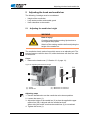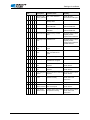
1
DA_512-211_deen_12-2013.qxd:DA-6-pages.qxd 512/532 04.12.2013 12:38 Uhr Seite 3 Service Instructions All rights reserved. Property of Dürkopp Adler AG and protected by copyright. Any reuse of this content, including extracts thereof, is prohibited without the prior written approval of Dürkopp Adler AG. Copyright © Dürkopp Adler AG - 2013 Contents 1 About this service manual ......................................................... 3 1.1 1.2 1.3 1.4 Scope of the service manual ........................................................ 3 Representation conventions – symbols and characters ............... 3 Other documents .......................................................................... 4 Liability.......................................................................................... 4 2 Safety information ...................................................................... 5 2.1 2.2 Basic safety instructions ............................................................... 5 Signal words and symbols used in warnings ................................ 6 3 Work principles........................................................................... 9 3.1 3.2 3.3 3.3.1 3.3.2 3.3.3 3.3.4 3.3.5 3.3.6 3.3.7 3.3.8 3.4 Order of settings ........................................................................... 9 Cable routing ................................................................................ 9 Removing the covers .................................................................. 10 Access to the machine bottom section ....................................... 10 Removing and fitting the head cover .......................................... 11 Removing and fitting the arm cover ............................................ 11 Removing and fitting the right-hand side cover .......................... 12 Removing and fitting the left-hand side cover ............................ 13 Removing and fitting the rear cover............................................ 13 Opening and closing the hook flap ............................................. 14 Removing and inserting the throat plate ..................................... 15 Surfaces on shafts ...................................................................... 17 4 Adjusting the light barriers...................................................... 19 4.1 4.2 4.3 Light barrier sensor disks ........................................................... 19 Adjusting the left and right switching flags.................................. 20 Thread clamp switching flag ....................................................... 21 5 Adjusting the hook and needle bar......................................... 22 5.1 5.2 5.3 Adjusting the needle bar height .................................................. 22 Adjusting the loop stroke and needle guard ............................... 23 Adjusting the distance between the hook tip and needle ........... 25 6 Adjusting the thread trimmer .................................................. 26 7 Adjusting the height of the fabric clamp lift........................... 27 8 Adjusting the thread wiper ...................................................... 29 9 Adjusting the thread regulator ................................................ 30 10 Adjusting the winder ................................................................ 31 10.1 10.2 Setting the fill volume ................................................................. 31 Adjusting the winding tension ..................................................... 32 11 Settings via software................................................................ 33 11.1 11.2 11.3 11.4 11.5 11.5.1 11.5.2 Control panel .............................................................................. 33 Switching on the sewing machine .............................................. 34 Reference the machine .............................................................. 34 Selecting a sewing pattern ......................................................... 35 Scaling axes ............................................................................... 35 Scaling the X-axis ....................................................................... 35 Scaling the Y-axis ....................................................................... 35 Service manual 512/532 Version 00.0 - 12/2013 1 Contents 11.5.3 Converting the buttonhole gap (class 532) ................................. 36 11.5.4 Converting the backtack dimensions (class 512) ....................... 36 11.6 Setting the speed........................................................................ 37 11.7 Checking the sewing pattern ...................................................... 37 11.8 Changing the sewing pattern ...................................................... 37 11.9 Winding....................................................................................... 38 11.10 Sewing ........................................................................................ 38 11.11 Counter ....................................................................................... 39 11.12 Interrupting sewing ..................................................................... 39 11.13 Protecting standard sewing patterns .......................................... 39 11.14 Storing sewing patterns .............................................................. 40 11.14.1Mapping memory buttons .......................................................... 40 11.14.2Sewing with memory buttons..................................................... 41 11.14.3Deleting the memory button assignments ................................. 41 11.15 Storing sewing pattern sequences ............................................. 41 11.16 Processing sewing pattern sequences ....................................... 42 11.17 Deleting sewing pattern sequences............................................ 42 11.18 Stopping sewing ......................................................................... 43 11.19 Editing parameters in the memory.............................................. 43 11.19.1Editing parameters in level M1 .................................................. 43 11.19.2Editing parameters in level M2 .................................................. 44 11.20 Resetting parameters to factory settings .................................... 44 11.21 Editing sewing patterns externally .............................................. 45 11.22 Working with a USB stick ........................................................... 46 11.23 Error messages .......................................................................... 48 11.24 Loading software via a USB stick ............................................... 51 11.24.1Loading the main program......................................................... 51 11.24.2Loading sewing patterns............................................................ 51 11.24.3Setting parameter U085 (class 532) .......................................... 52 11.24.4Checking the software version................................................... 52 2 12 Service settings via software .................................................. 53 12.1 12.2 12.2.1 12.2.2 12.3 12.4 12.4.1 12.4.2 12.4.3 12.4.4 Basic software operation ............................................................ 53 Accessing the technician level.................................................... 54 Editing parameters in level 1 ...................................................... 54 Editing parameters in level 2 ...................................................... 54 Setting the blade position ........................................................... 55 Loading software via a USB stick ............................................... 57 Loading the main program.......................................................... 57 Loading sewing patterns............................................................. 57 Setting parameter U085 (class 532) ........................................... 58 Checking the software version ................................................... 58 13 Maintenance work .................................................................... 59 13.1 13.2 13.3 Lubrication .................................................................................. 59 Adjusting the lubrication for the hook ......................................... 61 Cleaning work ............................................................................. 62 14 Appendix ................................................................................... 63 14.1 14.2 Software error messages ........................................................... 63 Circuit diagram ........................................................................... 65 Service manual 512/532 Version 00.0 - 12/2013 About this service manual 1 About this service manual This manual for the 512/532 sewing machines has been compiled with the utmost care. It contains information and notes in order to make long-term and reliable operation possible. 1.1 Scope of the service manual This manual describes the setting and maintenance work for sewing machines 512/532. It applies to all submodels. The intended use and set-up is described in the operating manual. 1.2 Representation conventions – symbols and characters Various information in this manual is represented or highlighted by the following characters in order to facilitate easy and quick understanding: Correct setting Indicates proper setting. Malfunctions Specifies the faults that can occur due to an incorrect setting. Steps to be performed when operating the machine (sewing and equipping) Steps to be performed for servicing, maintenance, and installation Steps to be performed via the software control panel 1. The individual steps are numbered: 1. First step 2. 2. Second step ... The sequence of the steps must always be followed. • Lists are identified by bullet points. Result of performing an operation Change to the machine or in the display. Important Special attention must be paid to this point when performing a step. Service manual 512/532 Version 00.0 - 12/2013 3 About this service manual Information Additional information, e.g. on alternative operating possibilities. Observe order Specifies the work to be performed before or after a setting. References Reference to another section in the manual. Safety Important warnings for the machine operator are specially designated. Since safety is of particular importance, hazard symbols, levels of danger and their signal words are described separately in 3 Safety information. Orientation If the figure is unclear, indications of "right" and "left" are always from the operator's point of view. 1.3 Other documents This equipment includes components from other manufacturers. Each manufacturer has performed a hazard assessment for these purchased parts and confirmed their design compliance with applicable European and national regulations. The proper use of these components is described in each manufacturer's manual. 1.4 Liability All information in this operating manual was compiled with consideration to the state of the art, and applicable standards and regulations. The manufacturer cannot be held liable for damages resulting from: • Breakage and transport damages • Failure to observe operating manual • Improper use • Unauthorized modifications to the machine • Use of untrained personnel • Use of unapproved replacement parts 4 Service manual 512/532 Version 00.0 - 12/2013 Safety information 2 Safety information This section contains basic information for your safety. Read the information carefully before setting up, programming, maintaining or operating the machine. Make sure to follow the information included in this section. Failure to do so can result in serious injury and damage to the machine. 2.1 Basic safety instructions Only authorized personnel should use the machine. Anyone working on the machine should read the operating manual first. The machine should only be used in accordance with the manual. The operating manual should be available at the machine's location at all times. Observe the generally applicable safety and accident prevention regulations and the legal regulations concerning industrial safety and environmental protection. If you are using parts from other suppliers, please also observe the safety instructions and the operating manual provided by the respective manufacturer. All warnings on the machine must always be in legible condition and may not be removed. Missing or damaged labels should be replaced immediately. In the following situations, the machine must be disconnected from the power supply using the main switch or by disconnecting the power plug: • • • • Threading Replacing the needle or other sewing tools Leaving the workplace Performing service work, maintenance work and repairs Check the machine during use for any externally visible damage. Stop working as soon as you notice any changes to the machine. Report any changes to your supervisor. A damaged machine should no longer be used. Machines or machine parts that have reached the end of their service life must not continue to be used. They have to be disposed of correctly and in accordance with the applicable statutory provisions. Only qualified specialists may set up the machine. Anyone setting up the machine must have read the set-up instructions first. Service manual 512/532 Version 00.0 - 12/2013 5 Safety information Only qualified specialists may perform maintenance work and repairs. Anyone maintaining or adjusting the machine must have read the service manual first. Safety equipment should not be removed or deactivated. If this cannot be avoided for a repair operation or service setting, the safety equipment must be refitted and put back into service immediately afterwards. Only qualified electrical specialists may perform work on electrical equipment. The power cable must have a plug authorized for the country in which the machine is being used. The power plug may only be connected to the power cable by a qualified specialist. Work on live components and equipment is prohibited. Exceptions are defined in the specifications in DIN VDE 0105. Only use original spare parts from the manufacturer. Missing or faulty spare parts could impair safety and damage the machine. 2.2 Signal words and symbols used in warnings Warnings in the text are distinguished by color bars. The color scheme is oriented towards the severity of the danger. Signal words indicate the degree of risk: Signal words Signal words and the endangerment that they describe: Signal word DANGER Will result in serious injury or death. WARNING Can result in serious injury or death. CAUTION Can result in minor or moderate injury. ATTENTION 6 Endangerment Can result in property damage. Service manual 512/532 Version 00.0 - 12/2013 Safety information Symbols The following symbols indicate the type of risk to personnel: Symbol Type of danger General risk Risk of electric shock Risk of puncturing Risk of crushing Examples Examples of the layout of the warnings in the text: DANGER Type and source of risk Consequences of non-observance Measures for avoiding the risk This is what a warning looks like for a hazard that will result in serious injury or even death if not complied with. WARNING Type and source of risk Consequences of non-observance Measures for avoiding the risk This is what a warning looks like for a hazard that could result in serious injury or even death if not complied with. Service manual 512/532 Version 00.0 - 12/2013 7 Safety information CAUTION Type and source of risk Consequences of non-observance Measures for avoiding the risk This is what a warning looks like for a hazard that could result in moderate or minor injury if the warning is not complied with. CAUTION Type and source of risk Measures for avoiding the risk This is what a warning looks like for a hazard that could result in environmental damage if not complied with. ATTENTION Type and source of risk Measures for avoiding the risk This is what a warning looks like for a hazard that could result in material damage if not complied with. 8 Service manual 512/532 Version 00.0 - 12/2013 Work principles 3 Work principles 3.1 Order of settings Observe order Always adhere to the specified sequence for the individual setting steps. Always observe all notes marked with a and follow-up settings. in the margin on prerequisites ATTENTION Machine damage possible due to incorrect order. Always adhere to the working order specified in this manual. 3.2 Cable routing Binding the cable together Ensure that all cables in the machine are laid in such a way that moving parts are not impaired in their ability to function correctly. 1. Lay excessively long cables neatly in proper cable snakes. 2. Tie the snakes together using a cable tie. If possible, bind the snakes to fixed parts. The cables must be fixed firmly in place. 3. Cut off any protruding part of the cable tie. ATTENTION Machine damage and malfunctions can be caused by laying the cables incorrectly. Excess cabling may obstruct moving machine parts in their ability to function correctly. This will affect the sewing function and may cause damage. Lay excess cabling as described above. Service manual 512/532 Version 00.0 - 12/2013 9 Work principles 3.3 Removing the covers WARNING Risk of injury! Crushing injuries from moving parts. Switch the sewing machine off before you remove the covers or refit them. In many types of setting work, you will have to remove the machine covers first in order to access the components. Described here is how to remove the individual covers and how to reattach them. Just the cover that needs to be removed is then specified in the text for that particular type of setting work. 3.3.1 Access to the machine bottom section In order to access the components at the machine bottom section, you must first tilt the machine upper section to the left. Figure 1: Tilting the machine upper section to the left and setting it upright ① (1) - Machine upper section Tilting the machine upper section to the left Tilt the machine upper section (1) to the left as far as possible. Setting the machine upper section upright Set the upper machine section (1) upright. 10 Service manual 512/532 Version 00.0 - 12/2013 Work principles 3.3.2 Removing and fitting the head cover Figure 2: Removing and fitting the head cover ① ② (1) - Screw (2) - Eye guard ③ (3) - Head cover Removing the head cover 1. Unscrew the eye guard (2). 2. Loosen both screws (1). 3. Remove the head cover (3). Fitting the head cover 1. Fit the head cover (3). 2. Tighten both screws (1). 3. Tighten the eye guard (2). 3.3.3 Removing and fitting the arm cover Figure 3: Removing and fitting the arm cover ① ② (1) - Screw Service manual 512/532 Version 00.0 - 12/2013 (2) - Arm cover 11 Work principles Removing the arm cover 1. Loosen all 6 screws (1). 2. Remove the arm cover (2). Fitting the arm cover 1. Fit the arm cover (2). 2. Tighten all 6 screws (1) firmly in place. 3.3.4 Removing and fitting the right-hand side cover Figure 4: Removing and fitting the right-hand side cover ① ② (1) - Screw (2) - Right-hand side cover Removing the right-hand side cover 1. Loosen both screws (1). 2. Remove the right-hand side cover (2). Fitting the right-hand side cover 1. Fit the right-hand side cover(2). 2. Tighten both screws (1). 12 Service manual 512/532 Version 00.0 - 12/2013 Work principles 3.3.5 Removing and fitting the left-hand side cover Figure 5: Removing and fitting the left-hand side cover ① (1) - Screw ② (2) - Left-hand side cover Removing the left-hand side cover 1. Loosen all 3 screws (1). 2. Remove the left-hand side cover (2). Fitting the left-hand side cover 1. Fit the left-hand side cover (2). 2. Tighten all 3 screws (1) firmly in place. 3.3.6 Removing and fitting the rear cover Figure 6: Removing and fitting the rear cover ② ① (1) - Screw Service manual 512/532 Version 00.0 - 12/2013 (2) - Rear cover 13 Work principles Removing the rear cover 1. Loosen all 4 screws (1) on the rear cover (2). 2. Remove the rear cover (2). Fitting the rear cover 1. Fit the rear cover (2). 2. Tighten all 4 screws (1) on the rear cover (2) firmly in place. 3.3.7 Opening and closing the hook flap Figure 7: Opening and closing the hook flap ① (1) - Hook flap Opening the hook flap Fold down the hook flap (1). Closing the hook flap Fold up the hook flap (1). 14 Service manual 512/532 Version 00.0 - 12/2013 Work principles 3.3.8 Removing and inserting the throat plate Figure 8: Removing and inserting the throat plate I ① ② ③ ④ (1) - Springs of the fabric clamp (2) - Clamp feet (3) - Screw (4) - Work surface Removing the throat plate 1. Remove both springs of the fabric clamp (1). 2. Raise both clamp feet (2). 3. Loosen the screw (3) for the work surface (4). 4. Remove the work surface (4). Figure 9: Removing and inserting the throat plate II ⑤ ⑥ (5) - Thread puller blade connecting rod Service manual 512/532 Version 00.0 - 12/2013 (6) - Screw 15 Work principles 5. Open the hook flap ( Section 3.3.7, page 14). 6. Loosen the screw (6). 7. Unhinge the thread puller blade connecting rod (5). Figure 10: Removing and inserting the throat plate III ⑧ ⑦ (7) - Throat plate (8) - Screw 8. Loosen all 4 screws (8). 9. Remove the throat plate (7) upwards. Inserting the throat plate Figure 11: Removing and inserting the throat plate IV ⑨ (9) - Connecting rod pin for needle thread clamp 1. Insert the throat plate (7) from above. When doing this make sure that the hole in the needle thread clamp, which is located underneath the throat plate, and the connecting rod pin of the needle thread clamp (9) are mounted. 2. Mount the thread puller blade connecting rod (5) and make sure that the connecting rod grips properly. 3. Tighten all 4 screws (8) of the throat plate firmly in place. 4. Tighten the screw (6). 16 Service manual 512/532 Version 00.0 - 12/2013 Work principles 5. Close the hook flap ( Section 3.3.7, page 14). 6. Fit the work surface (4). 7. Tighten the screw (3) for the work surface (4) firmly in place. 8. Mount both springs of the fabric clamp (1). 3.4 Surfaces on shafts Screw onto the surface Figure 12: Surfaces on shafts 1 2 (1) - Surface (2) - Shaft Some shafts have flat surfaces at those points where the components are screwed on. This strengthens the connection and setting work is made easier. Always make sure that the whole screw is seated completely on the surface. Service manual 512/532 Version 00.0 - 12/2013 17 Work principles 18 Service manual 512/532 Version 00.0 - 12/2013 Adjusting the light barriers 4 Adjusting the light barriers WARNING Risk of injury! Crushing injuries from moving parts. Switch off the sewing machine before adjusting the light barriers. 4.1 Light barrier sensor disks The light barrier sensor disks are used as a reference for positioning by the control unit. Checking the correct setting The 180° disk points to the front and its lower edge is precisely lined up with the light barriers slots. Faults caused by an incorrect setting • • • • • Damage to fabric, wrinkling Incorrect needle position, needle jams in the hole Incorrect transport times Incorrect thread cutting Poor sewing results Cover • Remove rear cover ( Section 3.3.6, page 13). Figure 13: Light barrier sensor disks ② ① (1) - Thread trimmer sensor disk Service manual 512/532 Version 00.0 - 12/2013 (2) - Thread wiper and fabric clamp sensor disk 19 Adjusting the light barriers 4.2 Adjusting the left and right switching flags The switching flags are used as reference by the control unit for the position of the clamps in an X and Y-direction. Checking the correct setting The clamps are centered in both an X and Y-direction. Faults caused by an incorrect setting • Damage to the needle • Incorrect needle position Cover • Remove the right-hand side cover ( Section 3.3.4, page 12). • Remove the left-hand side cover ( Section 3.3.5, page 13). Figure 14: Adjusting the right switching flag ① ② (1) - Screw (2) - Switching flag, right Figure 15: Adjusting the left switching flag ① ② (1) - Screw 20 (2) - Switching flag, left Service manual 512/532 Version 00.0 - 12/2013 Adjusting the light barriers Adjusting steps 1. Loosen the screw (1). 2. Adjust the switching flag (2) accordingly. 3. Set the zero point via the control unit. 4. Tighten the screw (1). 5. Reference the machine. 4.3 Thread clamp switching flag The thread clamp switching flag is used as reference by the control unit for the thread clamp. The switching flag is located underneath the throat plate to the right and is factory set. Service manual 512/532 Version 00.0 - 12/2013 21 Adjusting the hook and needle bar 5 Adjusting the hook and needle bar The following 3 settings must be coordinated: • Height of the needle bar • Loop stroke position and needle guard • Hook clearance to the needle 5.1 Adjusting the needle bar height WARNING Risk of injury! Crushing hazard and puncturing injuries due to moving and sharp parts. Switch off the sewing machine before adjusting the height of the needle bar. The needle bar has 4 marker lines which serve as an adjusting aid. The top two lines are valid for class 512, while the bottom two lines are valid for class 532. Cover • Remove the head cover ( Section 3.3.2, page 11). Figure 16: Adjusting the needle bar height 512 ① ② (1) - Screw (2) - Needle bar 532 ③ ④ (3) - Marker line for class 512 (4) - Marker line for class 532 Adjusting steps 1. Use the handwheel to set the needle bar at its lowest position. 2. Loosen the screw (1). 3. Adjust the height of the needle bar (2) so that the applicable upper marker line (3/4) is aligned with the needle bar bush. When doing this make sure that the needle bar (2) is not twisted. 4. Tighten the screw (1). 22 Service manual 512/532 Version 00.0 - 12/2013 Adjusting the hook and needle bar 5.2 Adjusting the loop stroke and needle guard WARNING Risk of injury! Crushing hazard and puncturing injuries due to moving and sharp parts. Switch off the sewing machine before adjusting the height of the needle bar. Loop stroke The loop stroke is the path length from the lower dead center of the needle bar to the position where the hook is in the loop stroke position. Figure 17: Loop stroke ① ③ ② (1) - Center line of the needle (2) - Hook tip (3) - Groove Checking the correct setting When the machine is in the loop stroke position, the hook tip should be located exactly on the center line of the needle. The needle must be aligned so that the surface of the groove is parallel to the running direction of the hook tip. The hook tip should be located in the lower third of the groove. Faults caused by an incorrect setting • • • • Damage to the hook Damage to the needle Missing stitches Thread breakage Order Prerequisite: • A straight and undamaged needle must be inserted ( Operating manual, Section 4.7 Changing needles). Service manual 512/532 Version 00.0 - 12/2013 23 Adjusting the hook and needle bar Cover • Open the hook flap ( Section 3.3.7, page 14). Figure 18: Adjusting the loop stroke and needle guard ① ⑤ ② 512 ③ ④ (1) - Hook tip (2) - Hook (3) - Driver (4) - Screw 532 ⑥ ⑦ (5) - Needle (6) - Marker line for class 512 (7) - Marker line for class 532 Adjusting steps 1. Use the handwheel to adjust the needle bar so that the corresponding marker line (6/7) is aligned with the needle bar bush. 2. Loosen the screw (4). 3. Remove the cover ring. When doing this make sure that the hook (2) does not work loose and fall. 4. Twist the driver (3) accordingly. 5. Shift the driver (3) axially so that the needle (5) rests against the driver tip and is easily pushed aside. 6. Insert the cover ring. 7. Tighten the screw (4). 24 Service manual 512/532 Version 00.0 - 12/2013 Adjusting the hook and needle bar 5.3 Adjusting the distance between the hook tip and needle WARNING Risk of injury! Crushing hazard and puncturing injuries due to moving and sharp parts. Switch off the sewing machine before adjusting the distance between the hook tip and needle. Cover • Open the hook flap ( Section 3.3.7, page 14). Figure 19: Adjusting the distance between the hook tip and needle ① ② ③ ④ ⑤ ⑥ ⑦ (1) - Screw (2) - Eccentric (3) - Eccentric safety screw (4) - Needle (5) - Hook tip (6) - Tip of the hook path bearing (7) - Hook path bearing Checking the correct setting The hook tip (5) must be as close as possible to the groove of the needle, without touching it. The tip of the hook path bearing (6) should have a gap of 7.5 mm to the right side of the needle. Adjusting steps 1. Loosen the screw (1). 2. Loosen the safety screw (3) of the eccentric. 3. Adjust the hook path bearing (7) axially with the eccentric (2): • Eccentric to the left: reduce distance. • Eccentric to the right: increase distance. 4. Twist the hook path bearing (7) in such a way that it has a clearance of 7.5 mm to the right-hand side. 5. Tighten the safety screw (3) of the eccentric. 6. Tighten the screw (1). Service manual 512/532 Version 00.0 - 12/2013 25 Adjusting the thread trimmer 6 Adjusting the thread trimmer For the thread trimmer to work correctly, you must set the thread puller blade and the counter blade. WARNING Risk of injury! Crushing hazard and puncturing injuries due to moving and sharp parts. Switch off the sewing machine before adjusting the blades. Faults caused by an incorrect setting • Threads are not cut • Threads are cut too long Cover • Remove the throat plate ( Section 3.3.8, page 15). Figure 20: Adjusting the blades ① ⑤ ④ ③ ② (1) - Needle guide (2) - Thread trimmer lever (3) - Screw for thread trimmer lever (4) - Counter blade screws (5) - Counter blade Adjusting steps 1. Loosen the screw (3). 2. Set a distance of 18.5 mm between the front of the throat plate and the thread trimmer lever (5). 3. Tighten the screw (3). 4. Loosen the counter blade screws (4). 5. Move the counter blade and set a distance of 0.5 mm between the needle guide (1) and the counter blade (5). 6. Tighten the counter blade screws (4). 26 Service manual 512/532 Version 00.0 - 12/2013 Adjusting the height of the fabric clamp lift 7 Adjusting the height of the fabric clamp lift WARNING Risk of injury! Crushing hazard and puncturing injuries due to moving and sharp parts. Switch off the sewing machine before adjusting the fabric clamp lift. The following maximum heights apply when adjusting the fabric clamp lift: • Max. height for class 512: 17 mm • Max. height for class 532: 13 mm Cover Remove the arm cover ( Section 3.3.3, page 11). Figure 21: Adjusting the height of the fabric clamp lift ① (1) - Screw Adjusting steps 1. Loosen the screw (1). 2. Adjust the height by turning the fabric clamp lift on the shaft. When doing this observe the values for the maximum height. 3. Tighten the screw (1). Order After changing the height of the fabric clamp lift always check the setting of the thread wiper as well. Service manual 512/532 Version 00.0 - 12/2013 27 Adjusting the height of the fabric clamp lift Adjusting the fabric clamping feet (class 512) Faults caused by an incorrect setting • The two fabric clamping feet do not raise and lower synchronously. Figure 22: Adjusting the fabric clamping feet ① (1) - Screw Adjusting steps 1. Loosen the screws (1). 2. Align the fabric clamping feet synchronously. 3. Tighten the screws (1). 28 Service manual 512/532 Version 00.0 - 12/2013 Adjusting the thread wiper 8 Adjusting the thread wiper WARNING Risk of injury! Crushing hazard and puncturing injuries due to moving and sharp parts. Switch off the sewing machine before adjusting the thread wiper. Figure 23: Adjusting the thread wiper ① > 1.5 mm 23 - 25 mm (1) - Screw Adjusting steps 1. Loosen the screw (1). 2. Adjust the thread wiper. When doing this observe the minimum distance of 1.5 mm to the needle and the distance range of 23 to 25 mm when pivoting. When using a thin needle set the distance at 23 mm. 3. Tighten the screw (1). Service manual 512/532 Version 00.0 - 12/2013 29 Adjusting the thread regulator 9 Adjusting the thread regulator The thread regulator determines the needle thread quantity to be guided around the hook. The required thread quantity depends on the thickness of the material to be sewn, thread strength, and stitch length. Larger thread quantity for • thick material • high thread strengths • large stitch lengths Lower thread quantity for • thin material • low thread strengths • small stitch lengths Checking the correct setting Open the hook flap ( Section 3.3.7, page 14) and observe the thread running around the hook: The needle thread loop runs without surplus and without jumping around the largest hook diameter. Faults caused by an incorrect setting • Poor sewing results Figure 24: Adjusting the thread regulator 1 (1) - Thread regulator (2) - Fastening screw 2 Adjusting steps 1. Turn the handwheel and observe the run of the thread around the hook. 2. Loosen the fastening screw (2). 3. Move the thread regulator (1): • Larger thread quantity: Turn the regulator counterclockwise • Lower thread quantity: Turn the regulator clockwise 4. Tighten the fastening screw (2). 30 Service manual 512/532 Version 00.0 - 12/2013 Adjusting the winder 10 Adjusting the winder 10.1 Setting the fill volume Correct setting 1. Wind onto an empty bobbin ( Operating manual, Section 4.4). Winding stops automatically when the bobbin is filled to approx. 0.5 mm below the bobbin edge. ATTENTION Possible machine damage as a result of winding without sewing. When operated without sewing material the sewing feet and bobbin case in the hook can be damaged. Enable the winding mode ( Operating manual, Section 5.8 Winding) and remove the bobbin case from the hook to perform a test winding process. Figure 25: Setting the winder fill volume 1 4 3 2 (1) - Adjusting screw (2) - Clamping screw (3) - Thread guide plate (4) - Actuating lever Adjusting steps Rough adjustment 1. Loosen the clamping screw (2). 2. Align the actuating lever (4): • Smaller fill quantity: Push towards bobbin. • Larger fill quantity: Push away from bobbin. 3. Tighten the clamping screw (2). Fine adjustment 4. Loosen the adjusting screw (1). 5. Move the thread guide plate (3): • Smaller fill quantity: Push towards bobbin. • Larger fill quantity: Push away from bobbin. 6. Tighten the adjusting screw (1). Service manual 512/532 Version 00.0 - 12/2013 31 Adjusting the winder 10.2 Adjusting the winding tension Correct setting The correct winding tension depends on the anti-friction properties and thickness of the thread. Faults caused by an incorrect setting • Wrinkled seams • Poor sewing results Figure 26: Adjusting the winding tension ① (1) - Adjusting knob Adjusting steps 1. Turn the adjusting knob (2): • Greater tension: Turn clockwise • Less tension: Turn counterclockwise 32 Service manual 512/532 Version 00.0 - 12/2013 Settings via software 11 Settings via software 11.1 Control panel Figure 27: Control panel ⑤ ⑦ ⑥ ⑧ ⑨ ⑩ ⑪ ④ ③ ② ⑫ ① Control panel buttons: Button / LED Pos. Function (1) USB button with LED Saves/loads a sewing pattern to/from a USB stick. (2) Needle thread clamp button with LED Fixes needle thread during the first stitch. LED on = needle thread clamp on LED off = needle thread clamp off (3) Memory button Processes the memory functions. (4) Reset button Deletes an error and restores settings. (5) Ready button with LED Change between programming and sewing mode. LED on = sewing mode LED off = programming mode (6) Error LED LED on = error (7) Program display Displays parameters. Service manual 512/532 Version 00.0 - 12/2013 33 Settings via software Button / LED Pos. Function (8) +/- Program buttons Changes parameters and navigates forwards/backwards. (9) Function display Displays values of selected functions/programmes. (10) +/- Function buttons Changes values of functions/programmes. (11) Selection button Selects various functions. The corresponding function LED illuminates. (12) Sewing pattern memory buttons Saves sewing patterns. 11.2 Switching on the sewing machine 1. Set main switch to ON. The sewing pattern last sewn is loaded and the sewing pattern number is shown in the Program display. 11.3 Reference the machine 1. Press the Ready button. The LED in the button illuminates. 2. Press the Ready button. The LED in the button switches off. 34 Service manual 512/532 Version 00.0 - 12/2013 Settings via software 11.4 Selecting a sewing pattern ATTENTION Damage to the needle if the sewing pattern size does not match the clamping foot. Check the clamping foot, adjust if necessary. Prerequisite: • The machine is in the programming mode, the LED in the Ready button is off. 1. Press the +/- Function buttons until the desired sewing pattern number appears in the Function display. 11.5 Scaling axes Important Changes to the axes are only valid temporarily. For permanent changes and the ability to move the sewing pattern, see 11.14 Storing sewing patterns, page 40. 11.5.1 Scaling the X-axis 1. Press the Selection button until the X-axis LED illuminates. 2. Press the +/- Function buttons until the value for the X-axis is reached. 100 % corresponds to the specified dimensions for the selected sewing pattern. 11.5.2 Scaling the Y-axis 1. Press the Selection button until the Y-axis LED illuminates. 2. Press the +/- Function buttons until the value for the Y-axis is reached. 100 % corresponds to the specified dimensions for the selected sewing pattern. Service manual 512/532 Version 00.0 - 12/2013 35 Settings via software 11.5.3 Converting the buttonhole gap (class 532) The buttonhole gap is preset to 3.4 mm (3.4 mm = 100 %). The buttonhole gap can be adjusted by changing the percentage value. Buttonhole gap [mm] Value [%] Buttonhole gap [mm] Value [%] Buttonhole gap [mm] Value [%] 1 29 2,9 85 4,8 141 1,1 32 3 88 4,9 144 1,2 35 3,1 91 5 147 1,3 38 3,2 94 5,1 150 1,4 41 3,3 97 5,2 153 1,5 44 3,4 100 5,3 156 1,6 47 3,5 103 5,4 159 1,7 50 3,6 106 5,5 162 1,8 53 3,7 109 5,6 165 1,9 56 3,8 112 5,7 168 2 59 3,9 115 5,8 171 2,1 62 4 118 5,9 174 2,2 65 4,1 121 6 176 2,3 68 4,2 124 6,1 179 2,4 71 4,3 126 6,2 182 2,5 74 4,4 129 6,3 185 2,6 76 4,5 132 6,4 188 2,7 79 4,6 135 6,5 191 2,8 82 4,7 138 11.5.4 Converting the backtack dimensions (class 512) To convert the preset dimensions to the desired dimensions, apply the following formula: Value to be set = (100 % : preset dimension) * desired value Example Preset dimension in X-direction = 16 mm Desired value in X-direction = 10 mm Value to be set = (100 % : 16 mm) * 10 mm = 62.5 % 36 Service manual 512/532 Version 00.0 - 12/2013 Settings via software 11.6 Setting the speed Important Changes to the speed are only valid temporarily. For permanent changes see 11.14 Storing sewing patterns, page 40. 1. Press the Selection button until the Speed LED illuminates. 2. Press the +/- Function buttons until the desired speed is reached. 11.7 Checking the sewing pattern 1. Press the Selection button until the Sewing pattern shape LED illuminates. The Program display shows the current sewing pattern shape. 2. Press the Ready button to confirm the sewing pattern. The LED in the Ready button illuminates. 3. Press the foot pedal forwards. The clamp is lowered. 4. Press the +/- Function buttons to sew 1 stitch each. The Function display shows the current number of stitches. 5. Press the Reset button. The clamp is raised. 6. Press the Selection button until the Sewing pattern shape LED illuminates. 11.8 Changing the sewing pattern 1. Press the Selection button until the No. Pattern LED illuminates. 2. Press the +/- Function buttons until the desired sewing pattern number appears in the Function display. 3. Press the Ready button. Service manual 512/532 Version 00.0 - 12/2013 37 Settings via software 11.9 Winding Prerequisite: • Needle removed. • Needle thread not threaded. 1. Press the Ready button. The LED in the button illuminates. 2. Press the Ready button. The LED in the button switches off. 3. Press the Selection button until the Wind LED illuminates. 4. Press the Ready button. The LED in the button illuminates, the clamp is lowered. 5. Press the pedal forwards. Winding starts. 6. To stop winding, briefly press the pedal completely forwards. 7. Press the Ready button. The LED in the button switches off, the clamp is raised. 11.10Sewing Prerequisite: • The machine is in the sewing mode, the LED in the Ready button is illuminated. • Needle fitted. • Needle thread threaded. • Sewing pattern selected. 1. Insert the material. 2. Press the foot pedal forwards to the first position. The clamp is lowered. If the pedal is released, the clamp is raised. 3. Briefly press the foot pedal completely forwards. The sewing process starts. At the end of sewing the clamp is automatically raised. 38 Service manual 512/532 Version 00.0 - 12/2013 Settings via software 11.11Counter The counter can be used as a unit counter (parameter number U020) or as an automatic stop counter (parameter number U076). Prerequisite: • The machine is in the programming mode, the LED in the Ready button is off. 1. Press the Selection button until the Counter LED illuminates. 2. Press the Reset button to set the counter to 0. 3. Press the +/- Function buttons to set the cycle count. Each sewing end decrements the counter by 1. After reaching the number of cycles, a message appears in the display. 4. Insert a new bobbin. 5. Press the Reset button. The counter is reset. 11.12Interrupting sewing 1. Press the Reset button or press the pedal back. The sewing process is interrupted; the display shows error message E-50. 2. To continue sewing, press the Reset button or press the pedal forwards. 11.13Protecting standard sewing patterns Standard sewing patterns can be protected so that they are no longer displayed. Prerequisite: • The machine is in the programming mode, the LED in the Ready button is off. 1. Press the Memory and P1 buttons in quick succession. The Program display shows the sewing pattern number; the Function display shows 0 or 1: 0 = sewing pattern is displayed. 1 = sewing pattern is protected. 2. Press the +/- Program buttons to select another sewing pattern. 3. Press the Ready button to confirm the sewing pattern. 4. Press the +/- Function buttons to change between 0 and 1. 5. Press the Ready button to confirm the value. 6. Press the Memory button. Service manual 512/532 Version 00.0 - 12/2013 39 Settings via software 11.14Storing sewing patterns Standard sewing patterns can be stored on the sewing pattern memory buttons P1 to P5; 50 memory slots are available for this. The memory slots are accessed using the +/- Function buttons; memory slots up to 25 can also be accessed using the sewing pattern memory buttons and combinations thereof. Shortcuts for sewing pattern memory buttons Memory slot no. Shortcut Memory slot no. Shortcut Memory slot no. Shortcut Memory slot no. Shortcut P1 P1 P8 P1 + P4 P15 P4 + P5 P22 P2 + P3 + P4 P2 P2 P9 P1 + P5 P16 P1 + P2 + P3 P23 P2 + P3 + P5 P3 P3 P10 P2 + P3 P17 P1 + P2 + P4 P24 P2 + P4 + P5 P4 P4 P11 P2 + P4 P18 P1 + P2 + P5 P25 P3 + P4 + P5 P5 P5 P12 P2 + P5 P19 P1 + P3 + P4 P6 P1 + P2 P13 P3 + P4 P20 P1 + P3 + P5 P7 P1 + P3 P14 P3 + P5 P21 P1 + P4 + P5 11.14.1Mapping memory buttons Prerequisite: • The machine is in the programming mode, the LED in the Ready button is off. 1. Press the Memory and P2 buttons simultaneously. 2. Press the +/- Program buttons to select a memory slot. 3. Press the Ready button to confirm the memory slot. 4. Select the sewing pattern ( 11.4 Selecting a sewing pattern, page 35). 5. Scale the axes ( 11.5 Scaling axes, page 35). 6. Set the speed ( 11.6 Setting the speed, page 37). 7. Moving the position of the sewing pattern: • Press the Selection button until the X-axis LED flashes. • Press the +/- Function button and set the values: -5/+5. • Press the Selection button until the Y-axis LED flashes. • Press the +/- Function button and set the values: -4 /+4. 8. Press the Ready button to confirm the settings. 9. Press the Memory button to quit the memory mode. 10.Check the sewing pattern ( 11.7 Checking the sewing pattern, page 37). 40 Service manual 512/532 Version 00.0 - 12/2013 Settings via software 11.14.2Sewing with memory buttons 1. Press the sewing pattern memory button/button combination. 2. Press the Ready button. 3. Check the sewing pattern. 4. Sew. 11.14.3Deleting the memory button assignments Prerequisite: • The machine is in the programming mode, the LED in the Ready button is off. 1. Press the Memory and P2 buttons simultaneously. 2. Press the +/- Program buttons to select a memory slot. 3. Press the Ready button to confirm the memory slot. 4. Press the Reset button to delete the memory assignment. 5. Press the Ready button to confirm the deletion. 6. Press the Memory button to quit the memory mode. 11.15Storing sewing pattern sequences Besides the sewing patterns in memory slots P1 ~ P50, the automatic sewing machine also lets you use memory slots C01 ~ C25. Prerequisite: • The machine is in the programming mode, the LED in the Ready button is off. 1. Press the Memory and P3 buttons simultaneously. 2. Press the +/- Program buttons to select a memory slot (C01 ~ C25). 3. Press the Ready button to save the sewing pattern sequence. 4. Press the +/- Function buttons to select the 1st sewing pattern. 5. Press the +/- Program buttons to select the 2nd sewing pattern. 6. Press the +/- Function buttons to select the 3rd sewing pattern. 7. Press the +/- Program buttons to select the 4th sewing pattern, etc. 8. Press the Ready button to confirm the sewing pattern sequence. The Program display shows the memory slot; the Function display shows the number of sewing patterns. 9. Press the Memory button to quit the memory mode. Service manual 512/532 Version 00.0 - 12/2013 41 Settings via software 11.16Processing sewing pattern sequences Prerequisite: • The machine is in the programming mode, the LED in the Ready button is off. 1. Press the +/- Function buttons to select a sewing pattern sequence. 2. Press the Ready button to confirm the sewing pattern sequence. The Program display shows the sewing pattern sequence, e.g. <1.1>; The Function display shows the sewing pattern number. 3. Briefly press the pedal completely forwards. The sewing pattern is sewn. After completing sewing, the Program display shows the further sewing pattern sequence, e.g. <1.2>; the Function display shows the next sewing pattern number, etc. 4. To change between sewing patterns in a sequence, press the +/- Program buttons and select the sewing pattern. 11.17Deleting sewing pattern sequences Prerequisite: • The machine is in the programming mode, the LED in the Ready button is off. 1. Press the Memory and P3 buttons simultaneously. 2. Press the +/- Program buttons to select a sewing pattern sequence (C01 ~ C25). 3. Press the Ready button to confirm the sewing pattern sequence. 4. Press the Reset button to delete the sewing pattern sequence. 5. Press the Ready button to confirm the deletion. 6. Press the Memory button to quit the memory mode. 42 Service manual 512/532 Version 00.0 - 12/2013 Settings via software 11.18Stopping sewing CAUTION Risk of injury from needle and moving parts. Do not place your hand below the raised clamp. 1. Press the Ready button. The LED in the button illuminates. The control unit is in the sewing mode. 2. Set main switch to OFF. Note If the automatic sewing machine is switched off without pressing the Ready button, any modified values will not be saved. 11.19Editing parameters in the memory 11.19.1Editing parameters in level M1 Prerequisite: • The machine is in the programming mode, the LED in the Ready button is off. 1. Press and hold the Memory button for 3 seconds. The controller beeps 1x; the LED in the button illuminates. The Program display shows the parameter numbers; the Function display shows the parameter values. 2. Press the +/- Program buttons to select other parameters. 3. Press the Ready button to confirm the parameter. The LED in the button illuminates. 4. Press the +/- Function buttons to change values. 5. Press the Reset button to reset a changed value. 6. Press the Ready button to save a change. The LED in the button switches off. 7. Press the Memory button. The LED in the button switches off. Service manual 512/532 Version 00.0 - 12/2013 43 Settings via software 11.19.2Editing parameters in level M2 Prerequisite: • The machine is in the programming mode, the LED in the Ready button is off. 1. Press and hold the Memory button for 6 seconds. The controller beeps 2x; the LED in the button illuminates. The Program display shows the parameter numbers; the Function display shows the values. 2. Press the +/- Program buttons to select other parameters. 3. Press the Ready button to confirm the parameter. The LED in the button illuminates. 4. Press the +/- Function buttons to change values. 5. Press the Reset button to reset a changed value. 6. Press the Ready button to save a change. The LED in the button switches off. 7. Press the Memory button. The LED in the button switches off. 11.20Resetting parameters to factory settings Prerequisite: • The machine is in the programming mode, the LED in the Ready button is off. 1. Press and hold the Memory button for 6 seconds. The LED in the button illuminates. 2. Select parameter number U098 by using the +/- Program buttons. 3. Press the Ready button. 4. Enter the function value 1 by using the +/- Function buttons. 5. Press the Selection button. The controller beeps 1x. If the controller beeps 3x, the reset was unsuccessful. 6. Set parameter U085 for class 532. Setting parameter U085 (class 532) After resetting the parameters to the factory setting, parameter U085 must be set for the button sewing machine. 44 Service manual 512/532 Version 00.0 - 12/2013 Settings via software Prerequisite: • The machine is in the programming mode, the LED in the Ready button is off. 1. Press and hold the Memory button for 6 seconds. The LED in the button illuminates. 2. Select parameter number U085 by using the +/- Program buttons. 3. Press the Ready button. 4. Enter the function value 1 by using the +/- Function buttons. Press the Selection button. 11.21Editing sewing patterns externally ATTENTION Damage to the clamp if the sewing field size does not match the clamping feet. Check the clamping foot, adjust if necessary. Sewing patterns can be created and edited externally on a PC, e.g. using MS Excel or a text editor. Each row represents a stitch coordinate in an X and Y-direction. The maximum size of a sewing pattern is 400 x 300 x 1/10 mm. Negative values or comma separated values should not be entered. The operator does not have to perform any calculations to center the sewing pattern. The machine automatically centers the sewing pattern in the middle of the sewing field. To subsequently move the sewing pattern, see 11.14 Storing sewing patterns, page 40. Figure 28: Example of stitch coordinates in MS Excel or a text editor ① ② (1) - Starting point/first stitch Service manual 512/532 Version 00.0 - 12/2013 (2) - End point/last stitch 45 Settings via software Figure 29: Example of a sewing pattern ② ① (1) - Starting point/first stitch (2) - End point/last stitch 1. Enter the stitch coordinates in MS Excel or a text editor. The coordinates are accurate to a precision of 0.1 mm and are separated by a comma. Important In the text editor, the last row of coordinates must be terminated with a break so that the cursor is positioned in the next free row. 2. Saving a file: • File name: HSR2000 ~ HSR2099 • File format: .CSV 3. Save the file to a USB stick. Information It is also possible to create sewing patterns with DA-CAD 5000 and save them as a CSV file. 11.22Working with a USB stick Up to 10 of your own sewing patterns can be saved to the controller via a USB stick. Prerequisite: • The machine is in the programming mode, the LED in the Ready button is off. 1. Insert the USB stick into the USB port on the controller. The controller beeps briefly. 2. Press the USB button. 3. The LED in the button illuminates; the Program display shows parameter number U01. 4. Press the +/- Program buttons and select a memory slot (U01 ~ U10). 46 Service manual 512/532 Version 00.0 - 12/2013 Settings via software 5. Press the Ready button. The Function display shows values 1 to 4: • 1: Load a sewing pattern from a USB stick. • 2: Load a sewing pattern onto a USB stick. • 3: Delete a sewing pattern on the controller. • 4: Edit a sewing pattern. Saving a sewing pattern from a USB stick onto the controller: Value 1 1. Press the +/- Function buttons to set value 1. 2. Press the Selection button and select the sewing pattern file (HSR2000.csv ~ HSR2099.csv). 3. Press the Selection button to load a sewing pattern from the USB stick. The Function display shows the value ok; the controller beeps, the sewing pattern is saved. 4. Press the Reset button 2x. Saving a sewing pattern from the controller to the USB stick: Value 2 1. Press the +/- Function buttons to set value 2. 2. Press the Selection button to save the sewing pattern to the USB stick (HSW2001.scv = U01 ~ HSW2010.scv = U10). 3. Press the Selection button to confirm you want to save it. The Function display shows the value ok; the controller beeps, the sewing pattern is saved. 4. Press the Reset button 2x. Deleting a sewing pattern on the controller: Value 3 1. Press the +/- Function buttons to set value 3. 2. Press the Selection button. 3. Press the Reset button to confirm the deletion. The Function display shows "----". Service manual 512/532 Version 00.0 - 12/2013 47 Settings via software Editing a sewing pattern / contour test: Value 4 Figure 30: Editing a sewing pattern 1. Press the +/- Function buttons to set value 4. 2. Press the Selection button. The Program display shows a 1 for the first stitch; the Function display shows the value for the X-axis; the X-axis LED illuminates. 3. Press the +/- Function buttons to set the coordinates of the 1st stitch for the X-axis. 4. Press the Selection button. The Y-axis LED illuminates; the Function display shows the value for the Y-axis. 5. Press the +/- Function buttons to set the coordinates of the 1st stitch for the Y-axis. 6. Press the +/- Program buttons to select the next stitch. 7. Repeat steps 3 to 5 for all additional stitches. 8. Press the Ready button to save the edited sewing pattern. 9. Press the Reset button. The LED in the button switches off. 10.Press the USB button. The LED in the button switches off. 11.23Error messages If an error occurs, the Error LED illuminates. Error E E 48 Description Possible cause 8 Error table data Unable to read the table data 1 0 Error sewing The selected sewing pattern number pattern is not saved in ROM or is set to nonreadable. The sewing pattern is "0" Remedy Save the table data again. Press the Reset button to confirm the sewing pattern number. Service manual 512/532 Version 00.0 - 12/2013 Settings via software Error Description Possible cause Remedy E 3 0 Error needle The needle bar is not at the Check the connections. bar position top top position Turn the needle bar to the top dead center position. E 4 0 Error sewing field Sewing field exceeded Press the Reset button. Check X/Y scaling. E 4 2 Error scaling Sewing length is below 10 mm Press the Reset button. Check sewing pattern and X/Y scaling. E 4 5 Error sewing pattern data Sewing pattern data cannot Press the Reset button. be applied Check ROM. E 5 0 Pause Reset button pressed while Press the Reset button. sewing. Actuate the thread Sewing machine stopped. trimmer. Restart the sewing process. Machine head has moved. Fold back machine head. E 3 0 2 Error machine head E 3 0 5 Error thread Thread trimmer blade not trimmer position at home position Set main switch to OFF. Check sensor. E 3 0 6 Error thread Thread catcher not at catcher position home position Set main switch to OFF. Check sensor. E 3 3 2 Error clamp foot Clamp foot not at home position position Set main switch to OFF. Check sensor. E 5 0 1 Data read error Data not available or saved Save the data to a USB in the wrong format stick again. E 5 0 2 USB read error MOT file error Save the data to a USB stick again. E 5 0 3 SUM read error CHECKSUM data error in MOT file Save the CHECKSUM file to a USB stick again. E 5 0 4 End block error No end block in the MOT file Save the end block file to a USB stick again. E 5 0 5 USB read error USB stick not found Set main switch to OFF. Set main switch to ON. Reinsert USB stick. E 5 0 6 USB read error Unable to read U01 ~ U10. Set main switch to OFF. Set main switch to ON. Reinsert USB stick. E 5 0 7 Read error own U01 ~ U10 read error sewing patterns Download the data again. E 5 0 8 File error own U01 ~ U10 read error sewing patterns Check file type. E 5 0 9 File error own U01 ~ U10 read error sewing patterns Check file type. Service manual 512/532 Version 00.0 - 12/2013 49 Settings via software Error 50 Description Possible cause Remedy E 5 1 0 File error own U01 ~ U10 read error sewing patterns Check file type. Save data to USB again. E 5 1 1 USB write error File with the same name already exists Delete or rename file. E 5 1 2 USB read error Data cannot be loaded from USB stick Check USB stick. Reinsert USB stick. E 5 1 3 USB write error Data cannot be copied to USB stick. Check USB stick. Reinsert USB stick. E 5 5 0 Data write error Flash memory transfer error Set main switch to OFF. Repeat process. Replace the mainboard. E 5 5 1 Internal process Software error error Set main switch to OFF. Repeat process. Replace the mainboard. Update software. E 7 7 0 7 Motor signal 3 5 error Encoder / motor has no signal Check motor / encoder. E 7 3 6 Motor rotation error Motor stops after some time / encoder has no signal Check motor / encoder. E 7 3 7 Error Z phase Z signal no longer changes Check motor / encoder. E 7 3 8 Error Z phase Z signal inaccurate / encoder has no signal E 9 0 7 Error search X- X-axis sensor does not axis respond Set main switch to OFF. Check sensor. E 9 0 8 Error search Y- Y-axis sensor does not axis respond Set main switch to OFF. Check sensor. E 9 1 0 Error clamp foot Clamp foot sensor does not Set main switch to OFF. search respond Check sensor. E 9 1 1 Error clamp foot Clamp foot motor does not Set main switch to OFF. motor operate correctly Check motor and connection. E 9 1 2 Internal error E 9 1 3 Error thread Thread catcher sensor catcher search does not respond E 9 1 4 Error thread catcher motor - Check motor / encoder. Notify DA Service Set main switch to OFF. Check sensor. Thread catcher motor does Set main switch to OFF. not operate correctly Check motor and connection. Service manual 512/532 Version 00.0 - 12/2013 Settings via software 11.24Loading software via a USB stick ATTENTION Damage to the machine as a result of interrupting the copying process. Never remove the USB stick during the copying process. Only remove the USB stick after observing the specified time period. If a new version of the software becomes available, it can be downloaded from www.duerkopp-adler.com and loaded onto a USB stick. Important The following files must be saved to the USB stick: • FUYSTS.BT • LEEYSTS.BT1 • BT1mot • BT1PAT 11.24.1Loading the main program 1. Switch on the controller. 2. Insert the USB stick. 3. Press the USB button and wait approx. 3 seconds. 4. Press the Memory button. 5. Press the +/- Function buttons to set value 5 in the Function display. 6. Press the Selection button. The process for downloading to the controller starts. Important If a value is no longer shown in the Function display, the download process is complete. Now wait at least 25 seconds, otherwise it could corrupt the controller! 7. Switch off the controller. 8. Remove the USB stick. 11.24.2Loading sewing patterns 1. Switch on the controller. The current software version is briefly displayed. 2. Insert the USB stick. 3. Press the USB button and wait approx. 3 seconds. 4. Press the Memory button. Service manual 512/532 Version 00.0 - 12/2013 51 Settings via software 5. Press the P5 button. The process for downloading to the controller starts. This will take approx. 4 minutes. 6. Press the Reset button. 7. Remove the USB stick. The software transfer is complete. 11.24.3Setting parameter U085 (class 532) After installing new software, parameter U085 must be set for the button sewing machine. Prerequisite: • The machine is in the programming mode, the LED in the Ready button is off. 1. Press and hold the Memory button for 6 seconds. The LED in the button illuminates. 2. Select parameter number U085 by using the +/- Program buttons. 3. Press the Ready button. 4. Enter the function value 1 by using the +/- Function buttons. 5. Press the Selection button. 11.24.4Checking the software version 1. Press and hold the Memory button for 6 seconds. The controller beeps 2x; the LED in the button illuminates. 2. Press the +/- Program buttons and select parameter U097. 3. Press the Ready button. The current software versions are displayed: • M X.XX = Main program • P X.XX = Control panel • T X.XX = Servo motors • A X.XX = Sewing patterns 4. Press the +/- Function buttons and check the respective software version. 5. Press the Ready button. 6. Press the Memory button. The LED in the button switches off. 52 Service manual 512/532 Version 00.0 - 12/2013 Service settings via software 12 Service settings via software This chapter describes service settings such as • • • • The basic configuration of the machine Test functions for individual elements of the machine Calibration functions Presets for programs and functions Information regarding changes to the stitch length, thread tension, curve support, etc. as well as instructions for accessing and creating sewing programs can be found in the operating manual ( Operating manual, Section 5 Settings via software). 12.1 Basic software operation The software is controlled via the control panel. Figure 31: Display and control panel for the software ⑤ ⑥ ⑦ ⑧ ⑨ ⑩ ⑪ ④ ③ ② ⑫ ① (1) (2) (3) (4) (5) (6) - USB button with LED (7) - Program display - Needle thread clamp button with LED (8) - +/- Program buttons - Memory button (9) - Function display - Reset button (10) - +/- Function buttons - Ready button with LED (11) - Selection button - Error LED (12) - Sewing pattern memory buttons Service manual 512/532 Version 00.0 - 12/2013 53 Service settings via software 12.2 Accessing the technician level All of the settings in the service area are performed at the technician level. 12.2.1 Editing parameters in level 1 Prerequisite: • The machine is in the programming mode, the LED in the Ready button is off. 1. Press and hold the Memory button for 3 seconds. The controller beeps 1x; the LED in the button illuminates. The Program display shows the parameter numbers; the Function display shows the parameter values. 2. Press the +/- Program buttons to select other parameters. 3. Press the Ready button to confirm the parameter. The LED in the button illuminates. 4. Press the +/- Function buttons to change values. 5. Press the Reset button to reset a changed value. 6. Press the Ready button to save a change. The LED in the button switches off. 7. Press the Memory button. The LED in the button switches off. 12.2.2 Editing parameters in level 2 Prerequisite: • The machine is in the programming mode, the LED in the Ready button is off. 1. Press and hold the Memory button for 6 seconds. The controller beeps 2x; the LED in the button illuminates. The Program display shows the parameter numbers; the Function display shows the values. 2. Press the +/- Program buttons to select other parameters. 3. Press the Ready button to confirm the parameter. The LED in the button illuminates. 4. Press the +/- Function buttons to change values. 5. Press the Reset button to reset a changed value. 6. Press the Ready button to save a change. The LED in the button switches off. 7. Press the Memory button. The LED in the button switches off. 54 Service manual 512/532 Version 00.0 - 12/2013 Service settings via software 12.3 Setting the blade position Prerequisite: • The machine is in the programming mode, the LED in the Ready button is off. 1. Press and hold the Memory button for 6 seconds. The controller beeps 2x; the LED in the button illuminates. The Program display shows the parameter numbers; the Function display shows the values. 2. Press the +/- Program buttons and select parameter U099. 3. Press the Ready button to confirm the parameter. The LED in the button illuminates. The Program display shows "°°20". 4. Press button P1. The thread trimmer sensor disk travels to position. Figure 32: Thread trimmer sensor disk 5. Check to see if the hole of the thread puller blade and the needle guide of the throat plate are aligned: Figure 33: Checking the hole of the thread puller blade A C B Service manual 512/532 Version 00.0 - 12/2013 55 Service settings via software • Case A: The setting is wrong; the thread puller blade overlaps the counter blade: Adjust blade sensor upwards. • Case B: The setting is wrong; the thread puller blade overlaps the needle guide: Adjust blade sensor downwards. • Case C: The setting is correct. 6. Press button P1. The thread trimmer sensor disk travels to position again. 7. Check once again to see if the hole of the thread puller blade and the needle guide of the throat plate are accurately aligned. 8. Press the Ready button to save the change. The LED in the button switches off. 9. Press the Memory button. The LED in the button switches off. 56 Service manual 512/532 Version 00.0 - 12/2013 Service settings via software 12.4 Loading software via a USB stick ATTENTION Damage to the machine as a result of interrupting the copying process. Never remove the USB stick during the copying process. Only remove the USB stick after observing the specified time period. If a new version of the software becomes available, it can be downloaded from www.duerkopp-adler.com and loaded onto a USB stick. Important The following files must be saved to the USB stick: • • • • FUYSTS.BT LEEYSTS.BT1 BT1mot BT1PAT 12.4.1 Loading the main program 1. Switch on the controller. 2. Insert the USB stick. 3. Press the USB button and wait approx. 3 seconds. 4. Press the Memory button. 5. Press the +/- Function buttons to set value 5 in the Function display. 6. Press the Selection button. The process for downloading to the controller starts. Important If a value is no longer shown in the Function display, the download process is complete. Now wait at least 25 seconds, otherwise it could corrupt the controller! 7. Switch off the controller. 8. Remove the USB stick. 12.4.2 Loading sewing patterns 1. Switch on the controller. The current software version is briefly displayed. 2. Insert the USB stick. 3. Press the USB button and wait approx. 3 seconds. Service manual 512/532 Version 00.0 - 12/2013 57 Service settings via software 4. Press the Memory button. 5. Press the P5 button. The process for downloading to the controller starts. This will take approx. 4 minutes. 6. Press the Reset button. 7. Remove the USB stick. The software transfer is complete. 12.4.3 Setting parameter U085 (class 532) After installing new software, parameter U085 must be set for the button sewing machine. Prerequisite: • The machine is in the programming mode, the LED in the Ready button is off. 1. Press and hold the Memory button for 6 seconds. The LED in the button illuminates. 2. Select parameter number U085 by using the +/- Program buttons. 3. Press the Ready button. 4. Enter the function value 1 by using the +/- Function buttons. 5. Press the Selection button. 12.4.4 Checking the software version 1. Press and hold the Memory button for 6 seconds. The controller beeps 2x; the LED in the button illuminates. 2. Press the +/- Program buttons and select parameter U097. 3. Press the Ready button. The current software versions are displayed: • M X.XX = Main program • P X.XX = Control panel • T X.XX = Servo motors • A X.XX = Sewing patterns 4. Press the +/- Function buttons and check the respective software version. 5. Press the Ready button. 6. Press the Memory button. The LED in the button switches off. 58 Service manual 512/532 Version 00.0 - 12/2013 Maintenance work 13 Maintenance work 13.1 Lubrication ATTENTION Environmental damage due to lubricating grease Lubricating grease is a pollutant and must not enter the sewage system or the soil. Collect residual lubricating grease carefully and dispose of it along with greasy machine parts in accordance with the applicable statutory regulations. Please observe all safety and environmental protection instructions provided by the lubricant manufacturer. Figure 34: Lubrication I ① ① ① ① (1) - Points of lubrication Service manual 512/532 Version 00.0 - 12/2013 59 Maintenance work Figure 35: Lubrication II ① ① (1) - Points of lubrication Special grease for lubricating the machine components is available in the accessory kit. It can also be purchased from DÜRKOPP ADLER AG retail outlets under the following part number: • 9047 098004 Maintenance work: 60 Maintenance work Explanation Operating hours Lubricating the sewing machine Grease the points shown (1) on the sewing machine with special grease. 1000 Service manual 512/532 Version 00.0 - 12/2013 Maintenance work 13.2 Adjusting the lubrication for the hook Figure 36: Adjusting the lubrication for the hook ① (1) - Screw Adjusting steps 1. Loosen and remove the screw (1). The lubricating screw is located underneath the screw. The lubricating screw presses against the oil wick of the hook lubricator. 2. Adjusting the lubricating screw: • Loosening the screw: Increases lubrication for the hook • Tightening the screw: Reduces lubrication for the hook 3. Insert and tighten the screw (1). Service manual 512/532 Version 00.0 - 12/2013 61 Maintenance work 13.3 Cleaning work Lint and thread remnants should be removed after every eight hours of operation using a compressed-air pistol or a brush. Points that need to be cleaned particularly thoroughly: • Hook • Throat plate • Handwheel filter This cleaning work is described in the operating manual ( Operating manual, Section 6 Maintenance). ATTENTION Damage to the paintwork due to solvent-based cleaners. Solvent-based cleaners will damage paintwork on the machine. Only use solvent-free substances when cleaning the machine. 62 Service manual 512/532 Version 00.0 - 12/2013 Appendix 14 Appendix 14.1 Software error messages The remedial measures are to be processed in the order specified. Error Meaning Possible cause Error table data Unable to read the table data Remedial measures Process in the order specified! E 8 • Save the table data again. E 1 0 Error sewing pattern The selected sewing number pattern is not saved in ROM or is set to nonreadable. The sewing pattern is "0" E 3 0 Error needle bar position top The needle bar is not at the • Check the connections. top position • Turn the needle bar to the top dead center position. E 4 0 Error sewing field Sewing field exceeded • Press the Reset button. • Check X/Y scaling. E 4 2 Error scaling Sewing length is below 10 mm • Press the Reset button. • Check sewing pattern and X/Y scaling. E 4 5 Error sewing pattern Sewing pattern data cannot • Press the Reset button. data be applied • Check ROM. E 5 0 Pause • Press the Reset button to confirm the sewing pattern number. Reset button pressed while • Press the Reset button. sewing. • Actuate the thread trimmer. Sewing machine stopped. • Restart the sewing process. E 3 0 2 Error machine head Machine head has moved. • Fold back machine head. E 3 0 5 Error thread trimmer Thread trimmer blade not position at home position E 3 0 6 Error thread catcher Thread catcher not at home • Set main switch to OFF. position position • Check sensor. E 3 3 2 Error clamp foot position Clamp foot not at home position E 5 0 1 Data read error Data not available or in the • Save the data to a USB stick again. wrong format E 5 0 2 USB read error MOT file error • Save the data to a USB stick again. E 5 0 3 SUM read error CHECKSUM data error in MOT file • Save the CHECKSUM file to a USB stick again. E 5 0 4 End block error No end block in the MOT file • Save the end block file to a USB stick again. E 5 0 5 USB read error USB stick not found • Set main switch to OFF. • Set main switch to ON. • Reinsert USB stick. E 5 0 6 USB read error Unable to read U01 ~ U10. • Set main switch to OFF. • Set main switch to ON. • Reinsert USB stick. Service manual 512/532 Version 00.0 - 12/2013 • Set main switch to OFF. • Check sensor. • Set main switch to OFF. • Check sensor. 63 Appendix Error Meaning Possible cause Remedial measures Process in the order specified! E 5 0 7 Read error own sewing patterns U01 ~ U10 read error • Download the data again. E 5 0 8 File error own sewing patterns U01 ~ U10 read error • Check file type. E 5 0 9 File error own sewing patterns U01 ~ U10 read error • Check file type. E 5 1 0 File error own sewing patterns U01 ~ U10 read error • Check file type. • Save data to USB again. E 5 1 1 USB write error File with the same name already exists • Delete or rename file. E 5 1 2 USB read error Data cannot be loaded from USB stick • Check USB stick. • Reinsert USB stick. E 5 1 3 USB write error Data cannot be copied to USB stick. • Check USB stick. • Reinsert USB stick. E 5 5 0 Data write error Flash memory transfer error • Set main switch to OFF. • Repeat process. • Replace the mainboard. E 5 5 1 Internal process error Softwar error • • • • E 7 7 0 7 3 5 Motor signal error Encoder / motor has no signal • Check motor / encoder. E 7 3 6 Motor rotation error Motor stops / encoder has no signal E 7 3 7 Error Z phase Z signal no longer changes • Check motor / encoder. E 7 3 8 Error Z phase Z signal inaccurate / encoder has no signal E 9 0 7 Error search X-axis X-axis sensor does not respond • Set main switch to OFF. • Check sensor. E 9 0 8 Error search Y-axis Y-axis sensor does not respond • Set main switch to OFF. • Check sensor. E 9 1 0 Error clamp foot search Clamp foot sensor does not • Set main switch to OFF. respond • Check sensor. E 9 1 1 Error clamp foot motor Clamp foot motor does not • Set main switch to OFF. operate corrrectly • Check motor and connection. E 9 1 2 Internal error - E 9 1 3 Error thread catcher Thread catcher sensor search does not respond E 9 1 4 Error thread catcher Thread catcher motor does • Set main switch to OFF. motor not operate corrrectly • Check motor and connection. 64 Set main switch to OFF. Repeat process. Replace the mainboard. Update software. • Check motor / encoder. • Check motor / encoder. • Notify DA Service • Set main switch to OFF. • Check sensor. Service manual 512/532 Version 00.0 - 12/2013 Appendix 14.2 Circuit diagram Circuit diagram - Sheet 1 Service manual 512/532 Version 00.0 - 12/2013 65 Appendix Circuit diagram - Sheet 2 66 Service manual 512/532 Version 00.0 - 12/2013 Appendix Circuit diagram - Sheet 3 Service manual 512/532 Version 00.0 - 12/2013 67 Appendix Circuit diagram - Sheet 4 68 Service manual 512/532 Version 00.0 - 12/2013 Appendix Circuit diagram - Sheet 5 Service manual 512/532 Version 00.0 - 12/2013 69 Appendix 70 Service manual 512/532 Version 00.0 - 12/2013 DA_512-211_deen_12-2013.qxd:DA-6-pages.qxd 04.12.2013 12:38 Uhr Seite 2 Subject to design changes - Printed in Germany - © Dürkopp Adler AG - Service Instructions - 0791 512640 EN - 00.0 - 12/2013 DÜRKOPP ADLER AG Potsdamer Straße 190 33719 Bielefeld GERMANY Phone +49 (0) 521 / 925-00 E-mail [email protected] www.duerkopp-adler.com