1
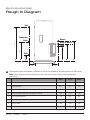
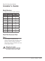
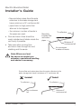
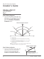
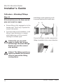
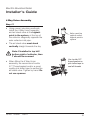
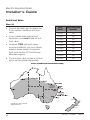
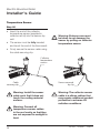
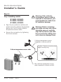
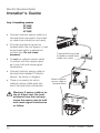
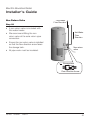
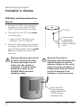
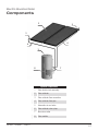
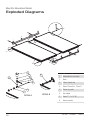
Installer’s Guide IMPORTANT INFORMATION For an easier installation, please read this document before you begin. On completion, sign and leave with owner. Electric Boosted Solar Water Heater Models: 2F136S 2F136SD 3F136S 3F136SD 4F136S 4F136SD 2S136ED 3S136ED 4S136ED Installation by a licensed tradesperson and in accordance with: • AS/NZS 3500.4 “National Plumbing & Drainage Code Hot Water Supply Systems – Acceptable Solutions” • Adherence to local authority and OH&S regulations • Victorian PIC Requirements For advice, repairs and service, call: 1300 365 115 (Australia) 0800 729 389 (New Zealand) Carefully remove all packaging and transit protection from the heater before installation. Dispose of the packaging responsibly using re-cycling facilities where they exist. Specifications and materials may change without notice. Effective for electric boosted solar water heaters manufactured and sold after 1 January 2012. H3163 025247 Rev. D Electric Boosted Solar Installer’s Guide Rough In Diagram 1 Flashing17 Model Numbers 2 Temperature Sensor 18 Safety Audit 3 Only if installing models 20 Removal of Existing Tank 4 Non Return Valve 21 Placement of New Tank 4 PTR Valve and Drain Down Line 22 Water Connections 5 GPO23 Pipes – Important Points 6 Tempering Valve 24 Collectors – Alignment and Inclination Commissioning the System 24 8 Commissioning Checklist 25 Collectors – Important Points 9 Installation Declaration 26 Collectors – Attaching to Roof 10 Collectors – Attaching Fittings 12 4 Way Union Assembly 15 Anti-Frost Valve 16 Components27 Exploded Diagrams 28 © 2012. All rights reserved. H3163 025247 Rev. D Electric Boosted Solar Rough In Diagram Hot Tempering Valve Return Drain to Waste Flow A B F E Cold C D 100 100 Approximate location of pipework. A tolerance of 25mm is acceptable to dimensions shown in table below. Note: Ensure pipes protrude horizontally from wall, and leave enough length of pipe to allow easy connections. 250 L 315 L 400 L Tank Height 1444 1754 1704 Overall diameter 617 617 705 A Hot water outlet 1211 1521 1445 B Tempered water outlet (mid-way between A and D) 624 779 742 C Flow to solar collectors 507 507 531 D Cold water inlet 195 195 219 E Drain to waste 592 592 616 F Return from solar collectors 628 838 642 H3163 025247 Rev. D 1 Electric Boosted Solar Installer’s Guide Model Numbers • Below is a list of model numbers: Model Capacity Number (L) Panel Management 2F136S 250 No 2F136SD 250 Yes 2S136ED 250 Yes 3F136S 315 No 3F136SD 315 Yes 3S136ED 315 Yes 4F136S 400 No 4F136SD 400 Yes 4S136ED 400 Yes Read This Document First Step 1 • This Installer’s Guide and the Owner’s Manual (also included in the product carton) contain important information about installation and use of this water heater. Note: For an easier installation, please read this document before you begin. 2 H3163 025247 Rev. D Electric Boosted Solar Installer’s Guide Safety Audit Step 2 • Arrive at site, park vehicle as close as allowable to installation, and conduct a safety audit, also known as Work Method Statements (WMS) or Job Site Analysis (JSA). • Prior to working at heights, it is the responsibility of the installer to ensure that all practices are compliant with any relevant OH&S legislation. Note: Do not commence a job where the risks cannot be controlled. • Refer to local working at heights regulations. NSW Ref: “Safe Work on Roofs – Part 2 Residential” Code of Practice 2004, Work Cover NSW. H3163 025247 Rev. D 3 Electric Boosted Solar Installer’s Guide Removal of Existing Tank Step 3 • The existing tank (if applicable) should be drained and removed in a responsible manner. Note: Do not drain on to grass or garden beds. Placement of New Tank Step 4 • Safely position new storage tank on a level surface in accordance with all plumbing and building regulations. Note: We recommend a plinth be installed under the water heater where the water heater is subjected to wet conditions. • Refer to the section called “"Rough In Diagram" on page 1 for detailed information on position of plumbing. 4 Install a plinth under the water heater where the water heater is subjected to wet conditions H3163 025247 Rev. D Electric Boosted Solar Installer’s Guide Water Connections Step 5 • Using correct plumbing methods, connect the cold water pipe to the storage tank. • According to local regulations and the plumbing code, fit any and all valves that are necessary e.g. tempering valves, pressure limiting valves, line strainer, duo valves, cold water expansion valves etc. • We recommend the use of new valves for all Installation. Refer to plumbing code and/or local requirements. Hot water outlet Cold water inlet • The hot water line should be connected to the hot water outlet. H3163 025247 Rev. D 5 Electric Boosted Solar Installer’s Guide Pipes – Important Points Step 6 Critical: Due to the high temperature imposed by solar heated water, all solar system pipes and fittings must be DR brass and copper, including collector compression fittings (as supplied). No plastic pipes or fittings. • Flow and return lines must be installed as direct as possible between tank and collector. • Pipes must be fully insulated with UV stabilized insulation suitable for solar working temperatures. We recommend Armaflex DuoSolar / Solar insulation, minimum 13mm thick (refer to local regulations). Note: Warranty will be void if this minimum insulation requirement is not used. Pipes must be DR brass and copper. Refer to AS/NZS 3500.4. Pipes must be fully insulated with UV stabilized insulation suitable for solar working temperatures, minimum 13mm thick (refer to local regulations) No pipes can be higher than the air bleed valve • It is critical to stop any chance of an air lock developing, so ensure that: – no pipework is higher than the automatic air vent valve Pipes must have no high points that allow air to be trapped 6 H3163 025247 Rev. D Electric Boosted Solar Installer’s Guide – flow and return pipes from the solar collectors to the water storage tank have a minimum of 5° continuous fall – pipes have no high points that allow air to be trapped – the minimum number of bends in the pipes are used. • Flow and return lines should be neatly installed and hidden inside the roof cavity if possible. • Take care when running flow and return lines through the roof, cladding and the eaves. Must fully insulate flow and return pipes To collectors Minimum 5° continuous fall Use minimum number of bends Note: Where roof and the eaves are made from asbestos, specialised handling and advice is necessary. Ensure flow and return pipes from the solar collectors to the water storage tank have a minimum of 5° continuous fall Incorrect To collectors Non continuous fall H3163 025247 Rev. D Correct To collectors Minimum 5° continuous fall 7 Electric Boosted Solar Installer’s Guide Collectors – Alignment and Inclination Step 7 Solar Collector Alignment • For the most efficient solar gain, the collectors must be aligned ±45° from true north (i.e. north west to north east). See Collector Orientation Compass below. Collector Orientation Compass Collector Orientation Compass True North True North A A NW NW 60° from true north 45° West West A. B. 45° 50° from true north 50° from true north 45° 45° C C C C NE B B 60° from true north NE Surface Plate East Surface Plate East Preferred range A. Dux Preferred range Complies with the Victorian Plumbing regulations when B. Complies with the installed Victorian Plumbing regulations when installed with two panels with two panels C.1. If A and B are not practical, an additional collector installedan additional collector can be installed C.1. If A and B arecan notbe practical, at the home owner's discretion in range C. home owner's discretion in range C. at the C.2. Complies with the Victorian Plumbing regulations when C.2. Complies with the installed Victorian Plumbing regulations when installed with three panels. with three panels. Note: When establishing the correctNote: Collector Orientation, please accountCollector Orientation, please account When establishing the correct for the Magnetic Declination of your for geographic location the Magnetic Declination of your geographic location Collector Inclination Guide Collector Inclination Guide Solar Collector Inclination True North True North • For the most efficient solar gain, the A collectors must be inclined within 10° to 45° from horizontal. See Collector Inclination Guide right. BA B A = 500mm, or greater if roof allows A = 500mm, or greater if roof allows B = Between 10° and 45° 8 B = Between 10° and 45° H3163 025247 Rev. D Electric Boosted Solar Installer’s Guide Collectors – Important Points Step 8 • Inspect fittings after collectors are pressurized with water. Critical: Fittings must be as tight as possible. Warning: Only pressurize the the collectors for inspection and de-pressurize them immediately after inspection. Critical: Do not leave collectors pressurised for longer than 24 hours. • To prevent damage, collectors should be left pressurised only when connected to the storage tank with appropriate pressure relief valves. • Collectors can be located a maximum of 20 metres (with minimal bends) from the storage tank if pipe layout is simple. Note: For more energy efficiency, locate the collectors as close as possible to the tank • This system is suitable for 2 storey homes. H3163 025247 Rev. D 9 Electric Boosted Solar Installer’s Guide Collectors – Attaching to Roof Step 9 For Both Metal and Tiled Roofs • Locate the lower mounting rail a minimum of 500mm distance from the gutter, or greater if roof allows. 500mm or greater Note: Ensure that the rail is parallel with the gutter. Step 10 For Metal Roofs Only • Fix roofing screws through the mounting straps on both sides, using rubber grommets to prevent corrosion. Note: A minimum of 3 roofing screws of 40mm length must be used to fix the collector strap to the truss. 500mm or greater • Ensure that the rail is parallel with the gutter. 10 H3163 025247 Rev. D Electric Boosted Solar Installer’s Guide For Tiled Roofs Only • Carefully remove a roof tile and locate the nearest roof truss. • Attach the first (2 per mounting rail) stainless steel collector strap to the mounting rail. Collector Strap • Shape the collector strap over the tile and position over the roof truss. Note: A minimum of 3 roofing screws of 40mm length must be used to fix the collector strap to the truss. • Ensure collector strap is located on truss vertically. Use minimum of 3 screws • Repeat this process for the collector strap at the other end of the mounting rail. Collector Strap Step 11 • Once the bottom rail has been secured, the collector can now be lifted on to the roof. Note: Ensure this is done with full consideration to OH&S regulations. Care should be taken. H3163 025247 Rev. D 11 Electric Boosted Solar Installer’s Guide Collectors – Attaching Fittings Step 12 All connections must be brass and all pipe work must be copper Hold fitting A while tightening nut B to prevent twisting the header pipe A B • Ensure fitting is fully engaged on to the header pipe. This is very important for correct connection. • To ensure leak proof installation, hold fitting A (see illustration in margin) while tightening nut B to prevent twisting the header pipe. Critical: Do not use multi grips or similar tool, as you will damage the brass fittings. Ensure you use the correct size spanner. Ensure the brass conetite compression fitting is installed in the correct direction Critical: The fitting must be as tight as possible on the barrel union to prevent the fitting coming loose. 12 H3163 025247 Rev. D Electric Boosted Solar Installer’s Guide Step 13 • Secure the collectors to the mounting rail with the Z brackets, screws, nuts and bolts provided with the water heater. Step 14 • Repeat the process for the second collector. Note: Ensure this is done with full consideration to OH&S regulations. Care should be taken. Step 15 • Now position the top mounting rail and repeat the above steps for that rail. Collector clamp bracket 24mm self tapping galvanised screw Collector strap Collector mounting rail • Join the top connections with the brass compression fittings supplied. H3163 025247 Rev. D 13 Electric Boosted Solar Installer’s Guide Step 16 • Connect collector flow and return pipes to the collectors. ~40mm ~40mm • Ensure that you connect the solar flow (cold) and solar return (hot) pipes to the correct connections: – the solar flow (cold) pipe connects to the bottom of the collectors – the solar return (hot) pipe connects to the top of the collectors, diagonally opposite to the solar cold pipe connection. • We suggest when you install pipes through roof, that you consider colour coding the pipe ends to show flow and return. Critical: During connection, the header pipe can move in the collectors. It is critical that the header pipe is centred to provide about 40mm of tube on both sides of the collector. 14 H3163 025247 Rev. D Electric Boosted Solar Installer’s Guide 4 Way Union Assembly Step 17 • Using correct plumbing methods, install the 4 Way Union assembly and air bleed valve at the highest point in the system, at the top of the collector diagonally opposite the solar collector inlet pipe. Valve must be vertical and at highest point in system • The air bleed valve must stand vertically straight towards the sky. Note: If installed in top left/ bottom right of collector, then T should be reversed. • When fitting the 4 Way Union assembly, we recommend Loctite 577 Thread sealant and/or a good quality pink teflon tape to secure the air bleed valve. Tighten by hand. Do not use spanner. H3163 025247 Rev. D Use Loctite 577 thread sealant or pink teflon tape to seal all threads 15 Electric Boosted Solar Installer’s Guide Anti-Frost Valve Step 18 • Consult the table right to determine if your system needs an anti-frost valve. • If your model does require frost protection, you must install an antifrost valve. • However, TWO anti-frost valves must be installed if you live in alpine areas or areas subject to extreme frost, such as the ACT and Snowy Mountain regions. • The anti-frost valve comes in kit form and must be ordered separately. Tank Model Anti-Frost Valve Needed? 2F136S Yes 2F136SD No 2S136ED No 3F136S Yes 3F136SD No 3S136ED No 4F136S Yes 4F136SD No 4S136ED No Frost Protection Installation Map Auckland Locations in grey may be subject to frost. Wellington Christchurch 16 H3163 025247 Rev. D Electric Boosted Solar Installer’s Guide • Connect the anti-frost valve to the top collector connection, on the opposite collector to where the thermowell/air bleed valve is installed. Anti-Frost Valve • Ensure the valve is pointing down the collector towards the gutter, parallel to the collector. 1 Collector Anti-Frost Valve must point towards the gutter, parallel to the collector 2 Collectors A 3 Collectors A A B B B A - Normal position of anti-frost valve (if required) B - Position of second anti-frost valve (if required) Flashing Step 19 • As per local authority regulations, use an approved method of flashing on the flow and return lines, e.g. Dektite or lead collars. • Where flow and return lines penetrate the roof surface, the penetration must occur on the high side of the roof profile, not in the valley. • Seal the roof penetration with a flexible waterproof flashing. We recommend the use of the appropriate Dektite brand solar flashing (available for either tile or steel roofs). H3163 025247 Rev. D Flexible waterproof flashing Roof penetration must be on high side of tile 17 Electric Boosted Solar Installer’s Guide Temperature Sensor Step 20 • Insert the end of the collector temperature sensor (supplied in collector rail kit) into the sensor dry well. • The sensor must be fully inserted and touch the end of the thermowell. Warning: Extreme care must be taken to not damage the sensor by pulling on collector temperature sensor. • Firmly secure the sensor cable using the cable securing clip. Collector temperature sensor Cable securing clip Warning: Install the sensor cable such that it does not touch the roofing material surface. Sensor secured by clip Warning: The collector sensor cable is a silicon rubber that may require additional conduit protection in extreme UV radiation conditions. Warning: Conceal all temperature sensor cables in the roof cavity so that they are not exposed to sunlight or heat. 18 H3163 025247 Rev. D Electric Boosted Solar Installer’s Guide Step 21 Only if installing models 2F136SD, 2S136ED 3F136SD, 3S136ED 4F136SD, 4S136ED • Align the pin positions carefully and press home the collector temperature sensor into the 20 metre collector temperature sensor cable. • Secure the connection by tightening the thumb screws. Warning: If the collector temperature sensor cable is exposed to atmosphere, you must insulate the cable from UV radiation damage. Warning: Sensor connector pins align one way only. When attaching sensors, carefully align the connector pins with the correct holes, taking care not to bend or damage them. Collector temperature sensor (supplied in collector rail kit) Caution: Sensor connector pins align one way only Collector temperature sensor cable 1 3 2 3 2 1 20m collector temperature sensor cable (supplied in collector rail kit) H3163 025247 Rev. D 19 Electric Boosted Solar Installer’s Guide Only if installing models 2F136S 3F136S 4F136S • Connect collector sensor cable to a terminal block secured to the timber or metal truss inside the roof cavity. • If the terminal block cannot be located within the roof space, it must be enclosed within a waterproof junction box. Do not leave exposed. • Do not run collector sensor cable in contact with the copper pipes as it may melt and cause signal interference. Terminal block secured to timber or metal truss inside roof cavity MODULE SENSOR MODULE SENSOR H3163 TOP SENSOR BOTTOM SENSOR 20 Attach collector sensor cable to terminal block COLLECTOR SENSOR Warning: If sensor cable is on top of a steel roof, the heat produced from the roof may cause the sensor wire to melt and cause signal interference or failure. TOP SENSOR • There is no polarity for which collector sensor cable goes into which terminal block connection. BOTTOM SENSOR COLLECTOR SENSOR • Connect collector sensor cable to terminal block labelled “Collector Sensor” as shown in diagram. 025247 Rev. D Electric Boosted Solar Installer’s Guide Non Return Valve Step 22 Cold Water Flow Direction • A non return valve is included with this water heater. Hot Water Flow Direction • We recommend fitting the non return valve at the solar return pipe connection. • Ensure the non return valve is installed so that the flow direction arrow faces the storage tank. Non return valve • All pipe work must be insulated. Storage tank FLOW RELIANCE Flow Direction Arrow H3163 025247 Rev. D 21 Electric Boosted Solar Installer’s Guide PTR Valve and Drain Down Line Step 23 • Connect the PTR valve and plumb to waste to comply with AS/NZS 3500.4 and local plumbing codes. PTR valve • The pipe from the PTR valve must: – be easily seen Plumb to waste to comply with AS/NZS 3500.4 and local plumbing codes – pose no risk of damage to the building or injury to persons. • Plumb the drain down line to waste to comply with AS/NZS 3500.4 and local plumbing codes. This line must not be connected to the the PTR drain line. Warning: Extreme care should be taken as this drain down line may discharge very hot water once the system is operating. It must be safely plumbed to waste as per AS/NZS 3500.4 and local plumbing codes. Warning: The point of discharge from each drain line shall be located so that the release of steam or hot water does not cause a nuisance, is readily discernible and incurs no risk of damage to the building or injury to persons. Drain down line. Plumb to waste to comply with AS/NZS 3500.4 and local plumbing codes. 22 H3163 025247 Rev. D Electric Boosted Solar Installer’s Guide GPO Step 24 • Install a Weatherproof GPO for the system. • This water heater requires the following electrical connections: 1. Solar Pump Module – CONTINUOUS TARIFF must be used. 2. Supplementary Electrical Boost Element (3.6kW) – Off Peak recommended, single phase 240V A.C. supply. A 15 amp power supply is needed. • Separate continuous electrical power must be supplied to the Hotlogic controller. This ensures the protection features are enabled. Note: This water heater is designed to allow the tank boost to be connected to continuous or off peak power supply. Large daytime users of hot water that exceed the capacity of the off peak boost option should connect to continuous supply. Warning: Power cables should be routed away from any hot water pipes. If this is not practical, insulate the hot water pipes to avoid direct contact with the power cables. H3163 025247 Rev. D 23 Electric Boosted Solar Installer’s Guide Tempering Valve Step 25 • Fit the solar tempering valve that is included with this water heater. Note: Any adjustment to the valve should be made according to the valve manufacturer’s recommendations. Hot Tempered Cold Commissioning the System Step 26 • When the power is turned on, the Hotlogic will go through initialisation: Sensors (red) and Power (green) status lights will alternate for 4 seconds. • After the initialisation, if there are no red status lights visible on Hotlogic, the system is functioning normally. • If there are any red status lights visible, refer to the Owner’s Manual for a full list and description of possible errors. 24 H3163 025247 Rev. D Electric Boosted Solar Commissioning Checklist Tick Task See Step No. Installer’s Guide read 1 Safety audit conducted 2 Existing tank removed 3 New storage tank safely positioned on a level surface 4 Cold and hot water pipes connected 5 Collectors aligned and attached to roof 6 – 11 Fittings attached to collectors 12 – 16 4 Way Union Assembly fitted 17 Anti-Frost Valve fitted 18 Roof penetration sealed with a flexible waterproof flashing 19 Temperature sensor installed Non return valve fitted 22 PTR valve fitted 23 GPO installed 24 Tempering valve fitted 25 Commissioning the water heater 26 H3163 025247 Rev. D 20 – 21 25 Electric Boosted Solar Installation Declaration Location of Installation: ........................................................................................... ............................................................................................................................... ............................................................................................................................... Tank Serial Number: ............................................................................................... Tank Model Number: .............................................................................................. Date Installed: ............................ Terms and conditions of warranty will apply only if the below is signed by the installer. This notifies the manufacturer that all the requirements of proper installation have been carried out by the installer in accordance with the Installer’s Guide, Owner’s Manual, and any other documentation supplied with the water heater. Upon completion of installation, this document must be given to the home owner in its entirety. When required by the manufacturer, the home owner will provide this document as evidence that the installation of the water heater was carried out in accordance with installation requirements. Declaration I have installed the water heater in accordance with the above instructions. If the instructions have not been followed then I understand that the terms and conditions of warranty will be void. Name:..................................................................................................................... Signed: . ................................................................................................................. Company: .............................................................................................................. Plumber’s Licence Number: . .................................................................................. Date: .......................................... 26 H3163 025247 Rev. D Electric Boosted Solar Components a 2 5 3 6 4 1 7 8 System Components H3163 025247 Rev. D 1 Solar electric tank assembly 2 Solar collector 3 Solar collector flow connection 4 Solar collector flow pipe 5 Automatic air vent valve 6 Solar collector return pipe 7 Non return valve 8 Solar module 27 DETAIL C SCALE 1 : 10 10 DETAIL D Electric Boosted Solar Exploded Diagrams 13 14 12 11 15 16 DETAIL E A B C E D 1 1 System Components 8 8 2 2 6 6 3 3 4 4 5 5 3 3 7 7 DETAIL DETAIL A A DETAIL DETAIL B B 1 Automatic air vent valve 2 Bush 3 15mm female tee 4 Union 15mm M × 15mm C 5 Sensor dry well 6 Hex nipple 7 Union 1" C × ½" M 8 Union conetite 9 9 28 H3163 025247 Rev. D 1 1 2 2 6 6 3 3 Electric Boosted DETAIL A 8 8 4 Solar 4 5 5 Exploded Diagrams 9 3 3 7 7 DETAIL A DETAIL A DETAIL B DETAIL B DETAIL C SCALE 1 : 10 13 9 9 DETAIL C DETAIL C SCALE 1 : 10 SCALE 1 : 10 13 13 11 12 12 10 10 DETAIL D DETAIL D 14 12 11 15 16 DETAIL E 11 System Components 14 15 14 16 DETAIL E 15 16 DETAIL E 9 End stop 1" conetite 10 Union 1" C × ½" C 11 24mm galvanised screw, self tapping 12 Bolt 13 Bracket - clamp 14 Solar heater rail 15 Nut 16 Collector strap B C H3163 025247 Rev. D A A C B 29 Electric Boosted Solar Installer’s Guide H3163 025247 Rev. D