1
6HFWLRQ
,QWURGXFWLRQ
7KH3URMHFWRUV
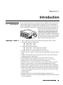
Mirage 2000/5000 projectors are professional quality DMD multimedia projectors
that use Digital Light Processing (DLP) technology from Texas Instruments to
produce high-brightness stereoscopic three-dimensional graphics. These models can
interface with IBM-compatible PC, Macintosh computers and workstations and,
with an optional video decoder installed, are
compatible with standard international video
formats. Mirage 2000/5000 projectors offer
exciting realism with large three-dimensional
graphic images for simulation, virtual reality and
other related 3D applications, all with a brilliance
that can stand up to even high levels of ambient
light. Features and other options include:
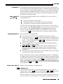
)HDWXUHV DQG 2SWLRQV ¡ Native resolution of 1280 x 1024, with other 2D resolutions fully scaleable
¡ Achievable brightness (ANSI lumens):
x Mirage 2000 = 2000
x Mirage 5000 = 5000
¡ Achievable Contrast Ratio (ANSI):
x Mirage 2000 = 300:1 ANSI, 450:1 full field
x Mirage 5000 = 300:1 ANSI, 500:1 full field
¡ 3D images (requires customized RGB signal at native resolution)
¡ Intuitive software controls for uniform color and light output in multiple-projector
walls
¡ Tandem horizontal and vertical sizing software control, with vertical stretch for
¡
¡
¡
¡
¡
¡
¡
¡
¡
¡
¡
changing aspect ratio when desired
Interchangeable lenses for diagonal screen sizes up to 40 or more feet
Display of NTSC, PAL and SECAM video input (requires optional decoder)
Display from PCs, VCRs, laser disc players, video cameras, etc.
Memory for up to 99 custom “channels” or source setups, switched via keypad
Intuitive on-screen menus as well as option allowing hidden direct control
Identical built-in and remote keypads, with controller and switcher compatibility
Built-in RS-232 and RS-422 ports for computer control and networked projectors
Motorized lens mount upgrade available for smooth and versatile remote control
of lens, with Intelligent Lens System (ILS™) for automatic recall of lens settings
from source-to-source
Optional shutter
Optional interfaces for connecting additional analog or digital sources
Modular components for easy servicing and minimum downtime. Durable exterior
of metal and polymer.
0LUDJH 8VHU·V 0DQXDO
,1752'8&7,21
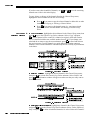
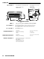
+RZ 7KH 3URMHFWRUV :RUN &RPSRQHQWV
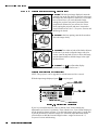
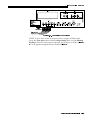
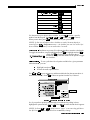
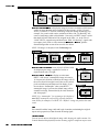
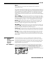
Mirage 2000/5000 models accept data/graphics and video input signals for projection
on to front or rear flat screens. High brightness light is generated by an internal
Xenon arc lamp (500W in the Mirage 2000, 1200W in the Mirage 5000), then
modulated by three DMD (digital micromirror device) panels that provide digitized
red, green or blue color information. Light from the “on” pixels of each panel is
reflected, converged and then projected to the screen through a single front lens,
where all pixels are perfectly superimposed as a sharp full-color 2D or 3D image.
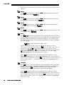
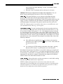
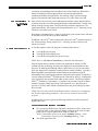
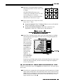
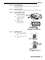
Mirage 2000/5000 models include an infrared (IR) remote keypad, line cord, a 9/64”
hex socket ball driver, and a User’s Manual. Make sure that you have all these items,
and note that purchasers also receive a Warranty Registration Card–complete this
card and return it directly to the manufacturer as soon as possible.
)LJXUH &RPSRQHQWV
'LIIHUHQFH %HWZHHQ 0RGHOV
3XUFKDVH
5HFRUGDQG
6HUYLFLQJ
The Mirage 2000 is the same projector as the Mirage 5000, but has a 500W lamp
rather than a 1200W lamp. This affects the brightness output and range of
adjustment.
Whether the projector is under warranty or the warranty has expired, Christie’s
highly trained and extensive factory and dealer service network is always available to
quickly diagnose and correct projector malfunctions. Service manuals and updates
are available to service technicians for all projectors.
Should you encounter a problem with the projector and require assistance, contact your
dealer or Christie. In many cases, any necessary servicing can be performed on site. If you
have purchased the projector, fill out the information below and keep with your records.
3XUFKDVH 5HFRUG
'HDOHU
'HDOHU 3KRQH 1XPEHU
3URMHFWRU 6HULDO 1XPEHU
3XUFKDVH 'DWH
,QVWDOODWLRQ 'DWH LI DSSOLFDEOH
* NOTE: The projector serial number is located on the projector's rear identification label
0LUDJH 8VHU·V 0DQXDO
6HFWLRQ
,QVWDOODWLRQ6HWXS
This section explains how to install and set up your projector. If you are familiar with the projector and want to
quickly set it up for temporary use, follow the Quick Setup instructions below. For a more complete setup, follow the
instructions and guides covered in the remaining subsections.
NOTES: 1) The lens is not installed for shipping. For instructions on how to install or replace a lens, refer to 4.5,
Replacing the Lens. 2) This section assumes that the optional video decoder module is installed.
4XLFN6HWXS
Follow these steps for quick setup of the projector in a standard floor mount position.
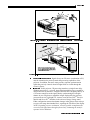
67(3 3RVLWLRQ WKH 3URMHFWRU
Set the projector at the expected throw distance (projector-to-screen distance) and
vertical position. See 2.3, Projector Position and Mounting and Appendix E. Make
sure that the projector is level from side-to-side (see 2.7, Leveling) and lens cap is off.
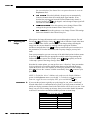
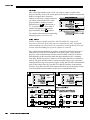
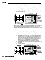
67(3 &RQQHFW D 6RXUFH
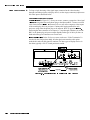
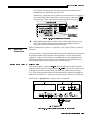
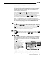
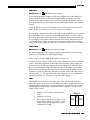
Locate the main input panel at the rear of the projector. The lower left area, labeled
,1387 , accepts an RGB input via BNC connectors. The upper right area (assuming
a video decoder is installed) accepts a composite video at ,1387 or S-video input at
,1387 . Connect your source to the appropriate panel connectors.
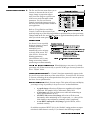
67(3 &RQQHFW WKH /LQH &RUG WR $& 3RZHU
Connect the projector’s line cord to the AC receptacle at the lower right rear corner of the
projector and to proper AC. The Mirage 2000 requires input power of 100-240 VAC, 5060 Hz @ 9 amps (@ 100 V). The Mirage 5000 requires input power of 200-240 VAC, 5060 Hz @ 8.5 amps (@ 200 V). Use the line cord provided with the projector. See Section 5.
:$51,1*
'R QRW DWWHPSW RSHUDWLRQ LI WKH $& VXSSO\ DQG FRUG DUH QRW
ZLWKLQ WKH VSHFLILHG YROWDJH DQG SRZHU UDQJH 6HH 6HFWLRQ 67(3 7XUQ WKH 3URMHFWRU 21
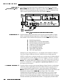
Using either the built-in or remote keypad, press 3RZHU and hold for approximately 1
second to turn the projector on (or press 3RZHU 21 ). Let the projector warm up for
about five minutes. The 32:(5 LED, located in the lower right corner of the rear
input panel, should glow a steady green.
67(3 6HOHFW D 6RXUFH
Using either the built-in or remote keypad, press ,QSXW , ,QSXW , ,QSXW , or ,QSXW to select
and display the image for the source you connected in Step 2. The display will resize
as needed, producing an image as large as possible for the type of source present.
0LUDJH 8VHU·V 0DQXDO
,167$//$7,21 $1' 6(783
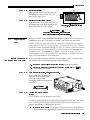
67(3 $GMXVW ,PDJH 67$1'$5' 12102725,=(' /(16
x
=220 With the input image displayed, rotate the
textured ring on the lens barrel to increase or decrease
the image size (this requires a zoom lens). If you don’t
have a zoom lens or you can’t adjust the image
enough, the projector may not be positioned at the
proper throw distance for your screen size. Power
down, unplug the projector and move it towards or
away from the screen. See 2.3, Projector Position and
Mounting for details.
x )2&86 At the lens opening, turn the focus tabs to
focus the image clearly.
x
2))6(76 Turn either or both of the knobs adjacent
to the lens if you need to align the image with your
screen—turn the top knob to raise or lower the image,
turn the bottom knob to shift the image left or right.
Re-check focus.
x
27+(5 Press 0HQX to refine other display
parameters as described in Section 3.
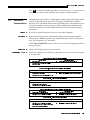
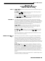
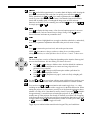
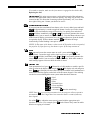
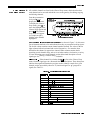
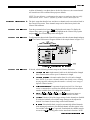
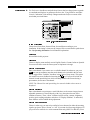
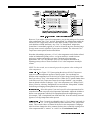
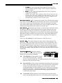
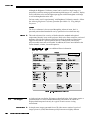
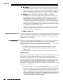
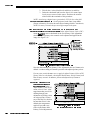
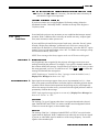
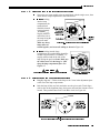
$GMXVW ,PDJH 5(48,5(6 02725,=(' /(16
NOTE: This projector can be upgraded to include motorized lens controls.
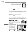
With the input image displayed, press
/HQV
on any keypad.
)LJXUH 0RWRUL]HG /HQV $GMXVWPHQWV
If you’ve just installed the lens, select “Calibrate Lens” before making any
adjustments (see Section 3 for details). Then, with the Lens Control menu displayed,
use the keypad as shown in Figure 2.1 to focus the image clearly and, if a zoom lens
is present, to increase or decrease image size. If desired, adjust horizontal and/or
vertical offsets to shift the lens and image location—ranges are shown in 2.3,
Projector Position and Mounting.
0LUDJH 8VHU·V 0DQXDO
,167$//$7,21 6(783
Press 0HQX to refine other display parameters, if necessary. See 3.5, Using Inputs and
Channels if you want to work with other source inputs or defined channels.
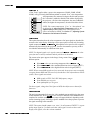
,QVWDOODWLRQ
&RQVLGHUDWLRQV
/LIWLQJ
+RLVWLQJ
Although this projector delivers a high brightness quality output, final display quality
could be compromised if the projector is not properly installed. This subsection
discusses issues you should consider before proceeding with a final installation. Even
if you do not intend to use the projector in a fixed and permanent installation, this
subsection will help you to better understand what you can do to enhance display
performance.
Never lift or suspend a projector by its feet or any other component.
Remove the lens and securely wrap hoisting cabling and safety straps around the
entire projector. Whether inverted or not, attach to the proper Christie ceiling mount
only. Never suspend or “fly” this model.
NOTE: Mirage 2000/5000 projectors cannot use a Christie Hoisting/Stacking Kit for
hoisting into place.
6WDFNLQJ
,QVWDOODWLRQ 7\SH
Mirage 2000/5000 projectors cannot be stacked.
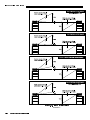
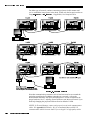
Choose the installation type which suits your needs: front or rear screen, floor mount
or inverted mount.
)URQW 6FUHHQ )ORRU 0RXQW ,QVWDOODWLRQ
$'9$17$*(6
x
x
x
(DV\ WR VHW XS
&DQ EH PRYHG RU FKDQJHG TXLFNO\
(DV\ WR DFFHVV
&216,'(5$7,216
x
6KDUHV IORRU VSDFH ZLWK DXGLHQFH
)URQW 6FUHHQ ,QYHUWHG 0RXQW FHLOLQJ ,QVWDOODWLRQ
$'9$17$*(6
x
x
x
'RHV QRW WDNH XS DXGLHQFH VSDFH
3URMHFWRU LV XQREWUXVLYH
3URMHFWRU FDQQRW EH DFFLGHQWDOO\ PRYHG
&216,'(5$7,216
x
x
,QVWDOODWLRQ LV PRUH SHUPDQHQW
,W LV PRUH GLIILFXOW WR DFFHVV WKH SURMHFWRU
5HDU 6FUHHQ )ORRU 0RXQW ,QVWDOODWLRQ
$'9$17$*(6
x
x
x
3URMHFWRU LV FRPSOHWHO\ KLGGHQ
3URMHFWRU LV HDVLO\ DFFHVVHG
8VXDOO\ JRRG DPELHQW OLJKW UHMHFWLRQ
&216,'(5$7,216
x
5HTXLUHV VHSDUDWH URRP
5HDU 6FUHHQ ,QYHUWHG 0RXQW FHLOLQJ ,QVWDOODWLRQ
$'9$17$*(6
x
x
3URMHFWRU LV FRPSOHWHO\ KLGGHQ
8VXDOO\ JRRG DPELHQW OLJKW UHMHFWLRQ
&216,'(5$7,216
x
x
5HTXLUHV VHSDUDWH URRP
,QVWDOODWLRQ FRVW LV XVXDOO\ KLJKHU
5HDU 6FUHHQ )ORRU 0RXQW ZLWK 0LUURU
$'9$17$*(6
x
x
x
3URMHFWRU LV FRPSOHWHO\ KLGGHQ
8VXDOO\ JRRG DPELHQW OLJKW UHMHFWLRQ
&216,'(5$7,216
x
x
5HTXLUHV VHSDUDWH URRP
,QVWDOODWLRQ FRVW LV XVXDOO\ KLJKHU
5HTXLUHV OHVV VSDFH EHKLQG VFUHHQ WKDQ
RWKHU UHDU VFUHHQ LQVWDOODWLRQV
0LUDJH 8VHU·V 0DQXDO
,167$//$7,21 $1' 6(783
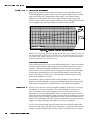
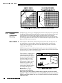
6FUHHQ 7\SH )URQW 6FUHHQ ,QVWDOODWLRQV
While there are two basic screen types, flat and curved, generally flat screens are
recommended for this projector. Flat screens offer a gain of about 1 with a viewing
angle just less than 180°. Incident light reflects equally in all directions so the
audience can see the display from various angles. Because of the low gain, flat
screens are most effective when ambient lighting is reduced, although this difference
may be negligible given the high brightness output from this projector.
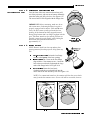
)LJXUH $XGLHQFH &RYHUDJH ZLWK )ODW 6FUHHQ
NOTE: Lenses for this projector are designed primarily for use with flat screens, but
the projector depth-of-field range allows the lens to be focused on curved screens as
well. While focus remains sharp in the corners, there may be significant pincushion
distortion, primarily at the top of the screen.
5HDU 6FUHHQ ,QVWDOODWLRQV
There are two basic types of rear screens: diffused and optical. A diffused screen has
a surface which spreads the light striking it. Purely diffused screens have a gain of
less than 1. The main advantage of the diffused screen is its wide viewing angle,
similar to that of a flat screen for front screen projection. Optical screens take light
from the projector and redirect it to increase the light intensity at the front of the
screen. This reduces it in other areas. A viewing cone, similar to that of a curved
front screen installation, is created.
To summarize, optical screens are better suited for brightly lit rooms where the
audience is situated within the viewing cone. Diffused screens may be better suited
when a wide viewing angle is required but there is low ambient room lighting.
6FUHHQ 6L]H Screen size may be from 5 to 40 feet diagonal, depending on the lens you are using.
For instance, a 1.2:1 lens can produce a 5 to 25 foot image size, whereas a 4-7:1
zoom lens produces an 8 to 40 foot image size. Choose a screen size which is
appropriate for your lens and application. Keep in mind that if the projector will be
used to display text information, the image size must allow the audience to recognize
all text clearly. The eye usually recognizes text clearly if eye-to-text distance is less
than 150 times the height of the letter. Small text located too far from the eye may be
illegible at a distance no matter how sharply and clearly it is displayed.
To fill a screen with an image, the aspect ratio of the screen should be equal to the
aspect ratio of the image. The aspect ratio of an image is expressed as the ratio of its
width to its height. Standard video from a VCR has a 4:3 aspect ratio. For example,
0LUDJH 8VHU·V 0DQXDO
,167$//$7,21 6(783
to display a VCR output with a 4:3 aspect ratio onto a 10 foot (3m) high screen, the
width of the screen must be at least 13.3 feet (4m).
6FUHHQ $VSHFW 5DWLR Aspect ratio describes the proportion of the screen and is expressed as the ratio of
width to height, such as “4:3” or “5:4” (see right). Although image size and image
aspect ratio can both be adjusted quickly through projector software, it is still a good
idea to choose a screen aspect ratio which is most appropriate for your intended
applications. Ideally, to exactly fill a screen with an image, the aspect ratio of the
screen should correspond to the aspect ratio of the image, which depends on the
source in use. For example, standard video from a VCR has a 4:3 ratio
(approximately), whereas a high resolution graphics signal typically has a 5:4 aspect
ratio. By default, images from your projector will be as large as possible and, with
the exception of graphics sources, will maintain their aspect ratio.
NOTE: With a few exceptions, sources with less than 1280 x 1024 resolution have a
4:3 aspect ratio. The normal aspect ratio for 1280 x 1024 sources is 5:4.
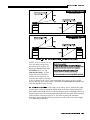
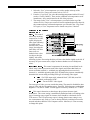
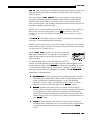
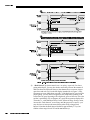
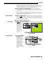
8VLQJ D 6FUHHQ
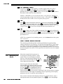
With one exception, XGA images will—
by default—resize to fill an SXGA (5:4)
screen. The exception is that video signals
will retain their aspect ratio, as shown in
Figure 2.3. In this case, fill the screen by
increasing Vertical Stretch to slightly
expand the image to the top and bottom
edges of the screen. For details, see 3.6,
Adjusting the Image.
)LJXUH $GMXVWLQJ D 9LGHR
,PDJH
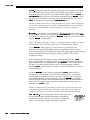
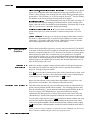
8VLQJ D 6FUHHQ
If you are using a 4:3 screen (but producing 5:4 images), images will—by default—
slightly overlap the screen vertically. To remedy, reduce Vertical Stretch so that the
“too tall” 5:4 image no longer spills over the top or bottom of the screen (Figure 2.4).
This control eliminates the need for simply moving the projector farther from the
screen, which would result in black borders for all sources. See 3.6, Adjusting the
Image.
NOTE: The Vertical Stretch adjustment may soften the image slightly, but is not
noticeable in most cases.
)LJXUH 8VLQJ D 6FUHHQ IRU D PL[ RI DQG VRXUFHV
0LUDJH 8VHU·V 0DQXDO
,167$//$7,21 $1' 6(783
,GHDO 5RRP /LJKWLQJ The high brightness output of this projector is certainly well suited for locations
where ambient lighting is less than optimum for projection, yet there are still many
simple things you can do to optimize your installation.
Visiting a movie theater can give you an idea of what makes an ideal projection
environment. Walls, floors and furnishings are dark and matte finished. A projection
room should not have white reflective ceilings or non-directional lighting such as
fluorescent lights. The white ceiling spreads light, making the room appear brighter.
Keep lighting and reflections to a minimum.
If it is not possible to eliminate fluorescent lights, consider using incandescent spot
lighting or parabolic reflectors ("egg crates") to direct light down to the floor. Light
dimmers or rheostats allow further control.
Outside windows are undesirable in any projection room. A small crack between
curtains on a sunny day can wash out a projected image. If you do have windows,
make sure that window coverings are opaque and overlapping — some window
coverings are designed to provide up to 100 percent blockage of outside light.
Ideally, the material should have a matte finish.
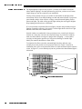
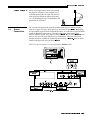
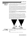
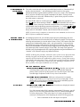
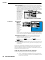
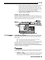
To minimize the effects caused by unwanted light from door and aisle ways,
carefully choose the position of your projector and screen. Figure 2.5 shows an
installation where poor screen placement allows too much unwanted light to enter the
screen. In Figure 2.6, screen and the projector are positioned so that unwanted light is
minimized.
)LJXUH 3RRU 6FUHHQ 3ODFHPHQW
0LUDJH 8VHU·V 0DQXDO
,167$//$7,21 6(783
)LJXUH %HWWHU 6FUHHQ 3ODFHPHQW
Even with all lighting removed it is still possible that room reflections within the
room can slightly degrade the image. Light from the projection screen should be
absorbed by the ceilings, walls and floors so that it will not be reflected back to the
screen. Again, keep reflective surfaces to a minimum.
2WKHU &RQVLGHUDWLRQV
Here are some other considerations and tips which can help you improve your
installation:
x
Ventilation is an important factor when preparing a projection room. The ambient
temperature should be kept constant and below 35°C (95°F). Keep the projector
away from heating and/or air conditioning vents. Changes in temperature can
cause drifts in the projector circuitry which may affect performance.
x
Keep the projector away from devices which radiate electromagnetic energy such
as motors and transformers. Common sources of these are slide projectors,
speakers, power amplifiers, elevators, etc.
x
For rear screen applications, less space is required if a mirror is used to fold the
optical path.
x
Choose the right screen size for the application:
¡
¡
¡
x
As screen size increases, magnification increases and reduces brightness.
Select a screen size which is appropriate for the venue, but not larger
than that required.
Installing a large screen in a small room is similar to watching television
close up; too large a screen can overpower a room. A good rule of thumb
is to be no closer than 1.5 times the width of the screen.
Larger screens require greater attention to lighting conditions.
When laying out the projection room, consider positioning the projector and
screen in a manner which will achieve maximum audience coverage and space
efficiency. For example, placing the screen along the larger wall in a rectangular
room will reduce audience coverage. Figure 2.7 shows two examples of how
audience coverage is maximized.
0LUDJH 8VHU·V 0DQXDO
,167$//$7,21 $1' 6(783
)LJXUH 6FUHHQ /RFDWLRQV IRU 0D[LPXP $XGLHQFH &RYHUDJH
Installation type, screen type, and lighting all affect where the projector is positioned.
In addition, both throw distance (the distance between the projector and screen) and
vertical position (the height of the projector in relation to the screen) must be
determined for every new installation. Both depend on the screen size and lens type
you are using. Make sure that the room can accommodate the required position of the
projector for the chosen screen size.
3URMHFWRU
3RVLWLRQDQG
0RXQWLQJ
7KURZ 'LVWDQFH
Throw distance is the distance between the projector's front feet and the screen. For
any installation, an accurate throw distance must be determined in order for the
image to be of the right size for your screen–the farther the projector is from the
screen, the larger the image.
NOTE: If your projector is tilted in relation to the screen, as is sometimes the case
for large venues or elevated installations, throw distance still represents the smallest
measurement between the screen and front feet.
Throw distance is roughly equal
to the horizontal width of the
screen multiplied by the type of
lens you are using. For example,
if you are using a 0.8:1 lens,
proper throw distance will be
approximately 0.8 [ the screen
width. Once you know your
screen size and lens, you can
estimate throw distance needed
(see example in Figure 2.8).
)LJXUH (VWLPDWLQJ 7KURZ 'LVWDQFH
For proper
6(( $33(1',; (
placement in an installation,
always refer to the throw distance formula and/or graph for your lens as listed in
Appendix E. Keep in mind that due to lens manufacturing tolerances for lens focal
length, actual throw distance can vary ±5% between lenses described as having the
same throw ratio.
,03257$17
0LUDJH 8VHU·V 0DQXDO
,167$//$7,21 6(783
9HUWLFDO +RUL]RQWDO 7+( 9(57,&$/ 326,7,21 of the projector in relation to the screen also depends on the
3RVLWLRQ
size of the screen and the lens type. Correct vertical position helps ensure that the
image will be rectangular in shape rather than keystoned (having non-parallel sides)
and that image focus and brightness both remain optimized.
In addition, vertical position of the image can be offset—that is, moved up or done—
either by turning the top knob on the front of the projector (the one nearest to the IR
sensor) in non-motorized projectors, or through software in motorized projectors.
Offsets range up to 130%, depending on the specific lens, whether it is motorized or
not, what amount of zoom is in effect and whether or not you are also offsetting
horizontally.
See Table 2.1 for the maximum percentage of the image that can be displayed above
or below the center of each type of motorized lens. These image offsets are also
illustrated in Figure 2.9.
NOTE: Shown are approximate motorized offset ranges—manual offsets standard in
Mirage 2000/5000 may differ.
0D[LPXP RI ,PDJH 2IIVHW IURP /HQV &HQWHU
7DEOH /HQV 7\SH
> > ² >
> 0D[ 5HFRPPHQGHG ,PDJH 2IIVHW
×
×
×
×
×
×
×
Ø
Ø
Ø
Ø
Ø
Ø
Ø
NOTE: VistaGRAPHX lens. Threaded lens adapter required.
The 0.8:1 lens is not recommended for use in SXGA models.
Motorized ZOOM feature is not available for VistaGRAPHX lenses.
0LUDJH 8VHU·V 0DQXDO
,167$//$7,21 $1' 6(783
)LJXUH 0D[LPXP 9HUWLFDO 2IIVHWV
Continued…
0LUDJH 8VHU·V 0DQXDO
,167$//$7,21 6(783
)LJXUH 0D[LPXP 9HUWLFDO 2IIVHWV &RQWLQXHG $//
/(16(6
NOTES: 1) If you cannot raise or
lower the image enough using
mechanical vertical offsets, try
adjusting V-Position in the Size
and Position menu (see 3.6,
Adjusting the Image). 2) If the
image becomes keystoned or
exhibits uneven brightness, the
projector may simply be too high
or low in relation to the screen. 3) Recommended offset ranges can be exceeded,
however this may affect image quality. 4) Simultaneous horizontal and vertical offset
limits the adjustment range of each.
7+( +25,=217$/ 326,7,21 of the image can be offset—that is, shifted left or right
of lens center—either by turning the bottom knob on the front of the projector (the
knob farthest from the IR sensor) in non-motorized projectors or through software in
motorized projectors. The maximum horizontal offset for lenses that can be installed
in this projector is shown in Figure 2.10. This value expresses the maximum
percentage of the image that can be projected to one side of the lens center (roughly
77%, depending on the lens).
0LUDJH 8VHU·V 0DQXDO
,167$//$7,21 $1' 6(783
)LJXUH 0D[LPXP +RUL]RQWDO 2IIVHWV $// /(16(6
0RXQWLQJ
For typical front or rear floor mounts, mount the projector on a
secure table or cart. Take care with a mobile cart—avoid
sudden stops, excessive force and uneven surfaces that may
cause the projector and cart combination to overturn.
The table or cart should be reasonably level. Fine adjustments to the projector level
can be made by adjusting the height of the projector legs; refer to 2.7, Leveling for
details.
6SHFLDO 0RXQWLQJ
Note that projector can be rotated and mounted at any vertical angle—i.e., you can
tilt the face of the projector up or down as much as desired for your installation. The
side-to-side tilt, however, must not exceed 15° (see Figure 2.11). This limit ensures
that the arc lamp in the projector operates properly and safely. Always make sure that
exhaust air from the projector does not vent towards the lens, otherwise you may
detect heat waves in your projected image.
)LJXUH +RUL]RQWDO DQG 9HUWLFDO 7LOW 5DQJHV
You must use the proper ceiling mount fixture (and/or stacking kit, if applicable) for
your projector. For more information, contact your dealer.
0LUDJH 8VHU·V 0DQXDO
,167$//$7,21 6(783
)ROGHG 2SWLFV In rear screen applications where space behind
the projector is limited, a mirror may be used
to fold the optical path. See right. The position
of the projector and mirror must be accurately
set—if considering this type of installation, call
your dealer for assistance.
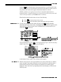
6RXUFH
&RQQHFWLRQV
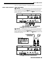
The rear panel of the projector provides standard input panels to which you may
connect a variety of sources. See Figure 2.12–the lower left area (,1387 ) typically
accepts an RGB signal from an external RGB source, or it can also be used for YPbPr
signals or additional video sources. The upper right panel–the optional Video
Decoder Module–accepts only composite video at ,1387 or S-video at ,1387 from
devices such as VCRs, laser disk players or DVD players. There are also several
optional interfaces available for connecting other sources at ,1387 Such an option
installs in the upper left area, just above ,1387 .
NOTE: For all connections, use only high-quality shielded cables.
)LJXUH 5HDU &RQQHFWRU 3DQHO
0LUDJH 8VHU·V 0DQXDO
,167$//$7,21 $1' 6(783
5*% 6LJQDOV
provides 5 BNCs (connectors) for linking to a variety of sources, typically to
an RGB source such as VGA, SVGA, XGA, Mac, PowerMac, DEC, Sun, SGI and
others. This projector supports multiple sync types with RGB signals: sync-on-green,
composite sync, and separate H & V syncs.
,1387 NOTE: Depending on the source, you may need a custom adapter cable with BNC
connectors at the projector end and a different type of connector at the other (such as
a 15-pin "D" connector for computer sources). Contact your dealer.
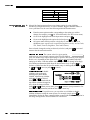
Connect the 6<1& BNC input(s) first. Then connect the red, green and blue source
outputs to the 5(', *5((1, and %/8( BNCs on the ,1387 panel. If the source uses
sync-on-green, only the red, green, and blue connections are required. If the source
provides a composite sync output, connect it to the 6<1& input labeled +25&203. If
the source provides separate horizontal and vertical sync outputs, connect horizontal
sync to the 6<1& input labeled +25&203 and connect vertical sync to 6<1& input
labeled 9(57 See Figure 2.13.
NOTES: 1) If for some reason the projector fails to recognize as an RGB signal,
specify this Color Space option within the Image Settings menu. See 3.6, Adjusting
the Image. 2) To connect YPbPr signals–such as from DVD or analog HDTV sources–to
,1387 , use the red, green and blue BNCs as described in YPbPr Signals later in this
section.
)LJXUH &RQQHFWLQJ 5*% ,QSXW
<3E3U 6LJQDO
Connect a YPbPr signal (component video) to ,1387 as shown in Figure 2.14.
&20321(17 9,'(2
0LUDJH 8VHU·V 0DQXDO
,167$//$7,21 6(783
)LJXUH &RQQHFWLQJ <3E3U 6LJQDO
NOTES: 1) If, for some reason, the projector fails to recognize a YPbPr signal,
specify this Color Space option within the Image Settings menu. See 3.6, Adjusting
the Image. 2) Do not connect digital component signals (known as YCbCr) to ,1387
. Use the appropriate digital interface installed at ,1387 .
0LUDJH 8VHU·V 0DQXDO
,167$//$7,21 $1' 6(783
&RPSRVLWH 9LGHR
The video decoder input panel provides simultaneous connection of both a composite
video source (,1387 ) and an S-Video source (,1387 ).
If connecting a composite video source, use the Composite BNC connector or the
RCA phono jack at ,1387 –do not use both as inputs. See Figure 2.15.
NOTE: If you want to loop a composite signal through to another projector or
display device, see Video Loop Through later in this section.
)LJXUH &RQQHFWLQJ &RPSRVLWH 9LGHR
0LUDJH 8VHU·V 0DQXDO
,167$//$7,21 6(783
69LGHR
The video decoder input panel provides simultaneous connection of both a composite
video source (,1387 ) and an S-Video source (,1387 ).
If connecting an S-Video source, use the 4-pin mini DIN connector or the Y and C
BNC connectors (luma and chroma) at ,1387 ²do not use both as inputs. See Figure
2.16.
)LJXUH &RQQHFWLQJ 69LGHR
NOTE: If you want to loop an S-video signal through to another projector or display
device, see Video Loop Through below.
0LUDJH 8VHU·V 0DQXDO
,167$//$7,21 $1' 6(783
9LGHR /RRS 7KURXJK
To loop a single incoming video signal input (connected at the video decoder)
through to another projector or display device, use the empty connector(s) adjacent to
this same input as described below.
&RPSRVLWH 9LGHR /RRS 7KURXJK
See Figure 2.17. From your source, connect a composite video signal
to ,1387 using either the small phono plug or the adjacent BNC. Connect a second
cable from whichever ,1387 connector is free to one of the composite video inputs
of the next display device or projector. Continue this looping method for each
projector, using either the phono plug or the adjacent BNC as input into ,1387 then using the other connector as an output (i.e., loop through). Whether you use the
BNC or the phono plug as input or output depends on the type of cable you have on
hand and what type of connectors are on each end.
&211(&7,216
In the Preferences menu, make sure “Video Termination” is
checked for the final projector only. All other projectors must have this option
unchecked in order for the signal to continue. For other types of display devices in
the chain, typically a “Hi-Z” switch position is needed.
9,'(2 7(50,1$7,21
)LJXUH &RQQHFWLRQV IRU &RPSRVLWH 9LGHR /RRS 7KURXJK
0LUDJH 8VHU·V 0DQXDO
,167$//$7,21 6(783
69LGHR /RRS 7KURXJK
&211(&7,216 See Figure 2.18. From your source, connect an S-video source signal
to ,1387 using either the 4-pin mini DIN or the 2 adjacent BNCs labeled Y and C.
Connect a second cable from whichever ,1387 connector is free to one of the Svideo inputs of the next display device or projector. Continue this looping method for
each projector, using either 4-pin mini DIN or the 2 adjacent BNCs as input into
,1387 then using the other connector(s) as an output (i.e., loop through). Whether
you use 4-pin mini DIN or the 2 adjacent BNCs as input or output depends on the
type of cable you have on hand and what type of connectors are on each end.
9,'(2 7(50,1$7,21 In the Preferences menu, make sure “Video Termination” is
checked for only the final projector. All other projectors must have this option
unchecked in order for the signal to continue. For other types of display devices in
the chain, typically a “Hi-Z” switch position is needed.
)LJXUH &RQQHFWLRQV IRU 69LGHR /RRS 7KURXJK
0LUDJH 8VHU·V 0DQXDO
,167$//$7,21 $1' 6(783
([WUD 9LGHR
If you want to use an extra video source in addition to the video source(s) connected at
,1387 or ,1387 connect either a Composite or S-Video source to ,1387 as shown in
Figure 2.19. Do not connect both types here simultaneously. NOTE: For additional video
inputs, install an optional Composite/S-Video Input Module at ,1387 .
² &20326,7( 25 69,'(2
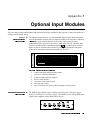
)LJXUH &RQQHFWLQJ DQ ([WUD 9LGHR 6RXUFH WR ,QSXW 2SWLRQDO ,QSXWV
Optional modules from Christie allow you to increase your total number of inputs
and/or accommodate different signal types, whether analog or digital. Any one of
these modules can be installed in the projector area labeled ,1387 . They include:
x
x
x
x
x
x
x
x
RGB 500 Input Module
RGB 400 Active Loop Thru Input Module
RGB 400 Buffered Amplifier Input Module
Composite/S-Video Input Module
PC250 Analog Input Module
Serial Digital Input Module
Digital HDTV Input Module
DVI / DFP Input Module
Alternatively, the analog interfaces (i.e., non-digital) can be installed in a Marquee
Case/Power Supply or Marquee Switcher, if desired, for use with the projector.
NOTES: 1) Audio ports on optional interfaces are non-functional. 2) Optional digital
interfaces cannot be used in a Marquee Case/Power Supply or Switcher. 3) Connect
analog HDTV signals directly to ,1387 or to any “RBG” input module installed at
,1387 —the optional HDTV Input Module used in earlier Christie projectors is not
needed or recommended . 4) See Appendix F, Optional Input Modules for a brief
description of each interface.
&RQQHFWLQJ D VZLWFKHU
0LUDJH You may wish to use one or more external Marquee Signal Switchers or a third party
8VHU·V 0DQXDO
switcher in order to significantly increase the number of sources you can select. If
you are using a Marquee Signal Switcher, connect the switcher’s RGB output to
,1387 and connect an RS-232 serial communication cable between the switcher and
the projector serial port labeled 6:,7&+(5 (see Figure 2.20). The switcher
communication link (permanently set at 9600 baud) enables you to access inputs
connected to the switcher in the same manner as those connected directly to the
projector. For most other third-party switchers, connect and access sources according
to the documentation provided with that switcher. Use high-quality shielded cables.
,167$//$7,21 6(783
NOTE: Make sure any Marquee Signal Switcher connected directly to the projector
is set as “Switcher #1”. If it is not, unplug the switcher and turn the thumbwheel to
“1” before plugging back in and connecting to the projector and/or network.
)LJXUH &RQQHFWLQJ D 0DUTXHH 6LJQDO 6ZLWFKHU
&RQQHFWLQJ 0XOWLSOH
6ZLWFKHUV
3RZHU
&RQQHFWLRQ
If you are using more than one Marquee Signal Switcher, daisy-chain the RS-232
switcher inputs/outputs together to form a complete network of inputs accessible
from the projector (you can network up to 9 switchers), and connect Switcher #1 to
the projector as shown in Figure 2.20. In addition, connect the RGB output from each
switcher to its matching slot on switcher #1–for example, connect the RGB output
from switcher #2 to slot #2 on switcher #1, and the RGB output from switcher #3 to
slot #3 on switcher #1. Note that slots used in this manner on switcher #1 are no
longer recognized as inputs to the projector–if you select a slot location that is
connected to another switcher’s RGB output, the projector will display the “no input
signal” error message.
Plug the projector’s high-current line cord into the line input socket located in the
lower right corner of the rear panel of the projector, then plug the 3-pronged end of
the line cord into a grounded AC outlet. Input voltage to Mirage 2000 must be 100240 VAC. Input voltage to Mirage 5000 must be 200-240 VAC. Use the proper
power source and the high-current rated line cord provided. See Section 5,
Specifications for all power requirements.
:$51,1*
'R QRW DWWHPSW RSHUDWLRQ LI WKH $& VXSSO\ DQG FRUG DUH
QRW ZLWKLQ WKH VSHFLILHG YROWDJH DQG SRZHU UDQJH
Caution: Once the projector is turned off, the lamp cooling fans will continue to
run for approximately five minutes to ensure that the projector and lamp have
sufficiently cooled, at which point the fans will automatically shut off. To avoid
thermal stress to the lamp, do not unplug the line cord while the lamp cooling fans
are running—and do not unplug the projector in order to power down.
0LUDJH 8VHU·V 0DQXDO
,167$//$7,21 $1' 6(783
2SHUDWLQJ
2ULHQWDWLRQ
The projector is set up at the factory for use in a front screen, floor mount orientation.
If your initial installation is ceiling mount or rear screen, displayed images may be
upside down and/or reversed. To correct, you must change the image orientation
from within the Preferences
menu (you may prefer to do
this before physically
installing the projector in its
final position/orientation).
In the Preferences menu,
highlight and select the
"Image Orientation" pulldown list. Select from Rear,
Inverted Rear, Front or
Inverted Front according to
your intended installation.
See Section 3, Operation for
further information.
/HYHOLQJ
=RRP)RFXV
/HQV2IIVHW
For most installations, the
lens surface of the projector
is parallel to the screen—this
prevents major keystoning of
the image (i.e., an image
with non-parallel sides). In
addition, the projector must
be kept level from side-to)LJXUH $GMXVWLQJ WKH )HHW +HLJKW
side in order for the lamp to
function safely. To make small corrections to the projector's level, rotate each leg as
necessary to raise or lower. For angled installations, see “Special Mounting” under
2.3, Projector Position and Mounting earlier in this section.
Once the projector is properly set up and producing an image, you are ready to make
quick lens adjustments. Refer to 3.3, Using the Keypad and 3.4, Navigating the
Menus if you are unfamiliar with using the keypad and menu system.
NOTE: A manual lens mount is standard on Mirage 2000/5000 projectors.
=RRP If you have a zoom lens installed, turn the textured ring of the lens
barrel to decrease or increase the size of the image at the current throw distance.
12102725,=('
If you have a zoom lens installed, press /HQV to display the Lens Control
menu. Select the “Zoom” option ( ) and adjust image size as desired with
or
. Refer back to Figure 2.1.
02725,=('
0LUDJH 8VHU·V 0DQXDO
,167$//$7,21 6(783
:$51,1*
.HHS ILQJHUV DZD\ IURP WKH OHQV RSHQLQJ ZKHQ
RSHUDWLQJ WKH PRWRUL]HG ]RRP IXQFWLRQ
)RFXV
12102725,=('
Near the lens opening, turn the lens focus tab until the image is as
sharp as possible.
Press /HQV to display the Lens Control menu. Adjust image clarity as
desired with
or
. Refer back to Figure 2.1.
02725,=('
NOTES: 1) Initially, your image may be so blurry you cannot recognize the “Focus”
menu option. Remember that /HQV activates the “Focus” control (#1)—from here,
press
or
to adjust. 2) If focus is not uniform throughout the image, bore
sight is likely poor. Contact your dealer for service.
/HQV 2IIVHW
Lens offsets move the lens and image. Try to achieve the desired overall image
position and best brightness while maintaining a rectangular image. If the brightness
looks uneven, or the edges do not look perfectly straight, the projector may not be in
the optimal position for your screen. See 2.3, Projector Position and Mounting for
full details. Lens offset ranges are also listed on page 5-1.
To relocate the image, turn either or both of the front knobs
adjacent to the lens. The top knob “Vertical” will raise or lower the image, the
bottom knob “Horizontal” will shift the image left or right.
12102725,=('
Press /HQV to display the Lens Control menu. Select either lens offset
or ) and move the image as desired with
or
. Refer back to
02725,=('
option (
Figure 2.1.
Other display adjustments are available through keypad commands and on-screen
menus—refer to Section 3, Operation.
70
,QWHOOLJHQW /HQV 6\VWHP
70
,/6 NOTE: Requires motorized lens, available as an upgrade for Mirage 2000/5000.
Once you’ve defined lens settings for the current display, you can automatically
recall these positions whenever you use this channel. This Intelligent Lens System
(ILS ) function is particularly useful if you are working with a variety of source
types that may differ in size and/or aspect ratio, since the custom lens settings you’ve
chosen for any channel will be quickly and accurately applied whenever you use that
channel.
TM
TM
(1$%/,1* ,/6 70 In the Lens Control menu, enable the “Intelligent Lens System”
option (highlight it and press (QWHU ). This will add the 4 lens positions—focus, zoom,
horizontal and vertical offset—to the current channel settings recorded in projector
memory (see 3.5, Using Inputs and Channels if you are unfamiliar with channels).
The lens will then automatically reposition itself according to these lens settings each
time you use this channel. The ILS is a global function—any lens settings you
subsequently define for other channels will also be recalled whenever you use those
channels.
TM
You can still change lens settings as usual when the ILS is enabled. Changes will be
recalled the next time you use the channel.
TM
0LUDJH 8VHU·V 0DQXDO
,167$//$7,21 $1' 6(783
70 To use consistent zoom, focus, and offset settings for all channels,
delete the “Intelligent Lens System” checkmark (highlight the option and press (QWHU ).
The lens will not move until you adjust one of its settings.
',6$%/,1* ,/6
2SHUDWLQJ 7LSV IRU /HQV 6HWWLQJV DQG ,/6
70
NOTES: 1) ILS requires motorized lens mount. 2) Accurate ILS performance
requires a calibrated lens mount. Calibrate after installation of a lens, and repeat if
the lens is moved or bumped. See Section 3.
TM
TM
When defining the focus, zoom, horizontal offset and vertical offset slidebar settings
for a given channel, keep in mind the following considerations for optimized ILS
performance:
TM
x
x
x
x
x
x
x
The lens mount must be calibrated.
When decreasing (
), values are always even (1004-1002-1000-etc.).
When increasing (
), values are always odd (1001-1003-1005-etc.).
Lens movements begin slowly and subtly before reaching full speed—changes
may not be evident on screen until after a second or two of
or
.
or
, lens movement gradually accelerates.
When holding
As with any setting, you can directly enter a value using the numbers on the
keypad, if desired. Press (QWHU before and after.
Because of how gears function, movement to an even value is always
approached from a higher value, even if the direction of lens movement must
reverse to do this. Likewise, an odd value is approached from a lower value.
This protocol helps ensure ILS accuracy. In general:
¡ If decreasing to an odd value, movement will reverse its approach.
¡ If increasing to an even value, movement will reverse its approach.
TM
x
To make small adjustments for ILS recall, always maintain the current odd or
even status for the new value—this will prevent the lens from reversing at a
point very near to the requested setting and settling in the area of extra travel
known as the “backlash” zone, an area which is not recognized by the ILS .
For accurate tweaking of an odd setting, press
. If even, press
.
)25 (;$03/( If the current setting is 1001 and you enter 1002, the lens must
move slightly beyond the requested setting before quickly reversing back
down to 1002. Although 1002 will appear in the menu, the physical location of
the lens will not be accurately recalled by the ILS .
Instead, if you need to slightly increase a current odd setting (such as 1001),
either press
as often as necessary or go to a nearby odd setting (1003,
1005, etc.) rather than switching to an even setting (1002, 1004, etc.). This
technique will prevent the lens from reversing and settling in the backlash
zone.
or
key before reaching a desired lens setting, then
Try to release the
continue as necessary with small incremental adjustments in the same
direction. If you “overshoot” slightly, do not reverse and “tweak” into place
unless you have overshot beyond the backlash zone (which can vary from 10
to 600 increments, depending on the function). Otherwise, the ILS function
will not recognize the final “tweaked” value when you return to this channel,
and lens performance will appear inaccurate. In general, use small
TM
TM
TM
x
TM
0LUDJH 8VHU·V 0DQXDO
,167$//$7,21 6(783
“incremental” fine-tuning only if the direction of lens movement has not
changed during an adjustment. See Figure 2.22.
Alternatively, simply enter a new position to reverse direction. For example, if
. If
the current setting is 2000, enter 2001 to start moving up—then press
current setting is 2001, enter 2000 to start moving down—then press
.
70
)LJXUH /HQV 6HWWLQJV DQG WKH ,/6
x
NOTE: Communication software is required for serial control. Contact your dealer
for details.
6HULDO3RUW
&RQQHFWLRQV
,I XVLQJ D FRPSXWHU
When adjusting lens offsets, slidebar values will not reach extremes of 0 or
9999. This is normal and does not mean that corresponding lens mount
movements failed to reach their physical extremes.
You may wish to use equipment other than the keypad for controlling the projector or
for performing other special functions. Such equipment—such as most personal
computers—requires a serial interface for sending and receiving communications
through the serial ports on the projector. Note that there are two different types of
serial communication ports on this projector as described below.
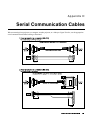
56 3RUWV
From most computers, connect an 56 serial communication cable between the
computer and the projector serial port labeled 56 ,1—this 9-pin D connector port
is located near the bottom center of the projector's rear control panel (see Figure
2.23). Then set the projector baud rate to match that of the computer (changing the
baud rate is described in 3.7, Adjusting System Parameters and Advanced Controls).
NOTE: Refer to Appendix D for complete cable wiring details.
)LJXUH 56 6HULDO &RQQHFWLRQ WR D &RPSXWHU
0LUDJH 8VHU·V 0DQXDO
,167$//$7,21 $1' 6(783
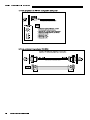
56 3RUWV
Some computers can provide 56 serial communications (often through a plug-in
adapter or external converter) rather than the more common RS-232. RS-422
communication has differential “transmits-and-receives” and is generally better
suited for long distances than is RS-232 communication. RS-422 is not compatible
with RS-232—connecting one to the other could damage the equipment at either end.
If you wish to control the projector with a computer and/or other controlling device
(such as the Two-Way Controller) having RS-422 capability, connect 56 serial
communication cables between the computer (or other device) and either (or both) of
the projector serial ports labeled 56—these 6-pin XLR connector ports are
located near the upper right corner of the projector's rear control panel (see Figure
2.24). Use an 56 port only if your equipment has RS-422 capability—always
first consult the documentation supplied with your equipment.
)LJXUH 56 6HULDO &RQQHFWLRQ WR D &RPSXWHU
:$51,1*
'R QRW XVH DQ 56 SRUW XQOHVV \RX DUH XVLQJ D
FRPSXWHU ZLWK 56 FDSDELOLW\ 7KH YROWDJH OHYHOV RI
WKLV VLJQDO FDQ GDPDJH LQFRPSDWLEOH HTXLSPHQW
,I XVLQJ D VZLWFKHU
0LUDJH You may wish to use one or more external Marquee Signal Switchers or a third party
8VHU·V 0DQXDO
switcher in order to significantly increase the number of sources you can select. If
you are using a Marquee Signal Switcher, connect the switcher’s RGB output to
,1387 and connect an RS-232 serial communication cable between the switcher and
the projector serial port labeled 6:,7&+(5 (refer back to Figure 2.20). The switcher
communication link (permanently set at 9600 baud) enables you to access inputs
connected to the switcher in the same manner as those connected directly to the
projector. For most other third-party switchers, connect and access sources according
to the documentation provided with that switcher.
,167$//$7,21 6(783
NOTE: See 2.4, Source Connections, “Connecting a Switcher” for complete details.
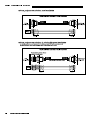
,I XVLQJ PXOWLSOH SURMHFWRUV 6HULDO &RPPXQLFDWLRQV
: To control multiple projectors with a computer/controller having
an RS-232 interface, first set them all to the same baud rate needed, then chain the
projectors together by connecting the 56 287 connector of the first projector
(already connected to the computer/controller) to the 56 ,1 connector of the next
projector in the chain.
56 1(7:25.
)LJXUH $GGLQJ $QRWKHU 3URMHFWRU YLD 56
: To control multiple projectors with a computer/controller having
an RS-422 interface, first set them all to the same baud rate needed, then chain the
projectors together by connecting the 56 3257 connector of the first projector
(already connected to the computer/controller) to the 56 3257 connector of the
next projector in the chain.
56 1(7:25.
)LJXUH $GGLQJ $QRWKHU 3URMHFWRU YLD 56
0LUDJH 8VHU·V 0DQXDO
,167$//$7,21 $1' 6(783
For either type of network, continue connecting projectors in this manner until
you’ve reached the last projector in the chain, so that only the last projector has an
empty 56 287 (or 56 3257, if applicable). See examples below.
)LJXUH $VVRUWHG 1HWZRUNV
Note that communication parameters such as baud rate must be set to match the
particular controlling device before connecting as a network—refer to the
documentation that came with your controlling device in order to determine the
proper baud rate. See 3.7, Adjusting System Parameters and Advanced Controls if you
need help changing the projector baud rate from its default of 19200.
NOTES: 1) To avoid damage, connect only properly wired serial communication
cables. See Appendix D for details. 2) It is recommended that each RS-232
communication cable be no more than 25 feet in length. Use high quality cables.
0LUDJH 8VHU·V 0DQXDO
,167$//$7,21 6(783
%DFNXS RU ´6SOLWµ 1HWZRUNV
In a typical network, broadcast serial communications or messages destined for a
specific projector travel through all serial ports in each projector regardless of
whether the messages originate from an RS-232 or RS-422 source (refer back to
Figure 2.27, bottom example). The communication path depends on the serial cabling
connected at each projector.
You may prefer the option of two separate communication paths—RS-232 or RS422—in your network, essentially creating a redundant “back-up” communication
path that can take over should a failed projector (or controller) prevent
communications via the other path. For this setup, connect each projector to the next
using both RS-232 and RS-422 ports.
Then enable the “Split Network”
setting in the Communications menu
for each projector present so that RS232 communications remain on RS232 paths only and RS-422
communications remain on RS-422
paths only (Figure 2.28). Each
projector can then receive and send
either type of message depending on
)LJXUH (QDEOH ´6SOLW 1HWZRUNµ
which controller initiates the
commands—should one path fail, the second “back-up” network path can be used.
Only one network should be active at a given time, as determined by the controller
(whether it is RS-232 or RS-422). Note that the “Broadcast Key” option is OFF.
,03257$17
:KHQHYHU GRZQORDGLQJ QHZ SURMHFWRU VRIWZDUH WR QHWZRUNV XVH D
VLQJOHURXWH QHWZRUN RQO\ ',6&211(&7 DQ\ UHGXQGDQW VHULDO FDEOLQJ
DQG 81&+(&. WKH ´6SOLW 1HWZRUNµ FKHFNER[ IRU HDFK SURMHFWRU
7ZR 'LIIHUHQW ´6SOLWVµ
There are two different split network configurations possible (Figure 2.29). Set up
whichever option best suits your application needs:
$ 63/,7 1(7:25. :,7+ 21( &21752//(5² If you have a single controller and
want a back-up serial link, connect one controller standard (e.g., RS-232) to
one physical end of the network and the other controller standard (e.g., RS422) at the other physical end of the network. Make sure the “Split Network”
option is enabled in the Communications menu. If a projector should then fail
anywhere in the network, communication with the remaining projectors can be
resumed in the opposite direction using the other standard. NOTE: This
configuration requires that both standards be available from a single
controller, or that you use an RS-232/RS-422 adapter.
% 63/,7 1(7:25. :,7+ 7:2 &21752//(56² If you have two controllers (one
RS-232 and one RS-422) and want one to be a back-up, connect each
controller to the appropriate port on the first projector in the network. Then
connect projectors together using both RS-232 and RS-422 ports as shown.
Make sure the “Split Network” option is enabled in the Communications
menu. Now, if either controller fails, you can simply switch to the other
controller and communicate via the other standard.
0LUDJH 8VHU·V 0DQXDO
,167$//$7,21 $1' 6(783
)LJXUH 7ZR 7\SHV RI 6SOLW 1HWZRUNV
3URMHFWRU 1XPEHUV
Each projector can be assigned a unique 3-digit projector number (for example, 001).
These numbers are necessary when you are working with multiple linked projectors,
enabling you to direct commands to a certain projector rather than always
broadcasting to the entire network. For complete information on how to assign
projector numbers, see 3.7, Adjusting System Parameters and Advanced Controls.
NOTE: To loop a single incoming video source through to another projector or
display device on a network, see Video Loop Through in 2.4, Source Connections.
0LUDJH 8VHU·V 0DQXDO
,167$//$7,21 6(783
.H\SDG
3URWRFROVDQG
&RQYHUVLRQ
At manufacture every keypad is assigned “A” as its default protocol, which is simply
a collection of settings that determine how the keypad operates. Once assigned, this
protocol remains in effect until it is changed—that is, the keypad will operate as it
currently does until you change its protocol.
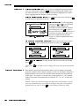
Protocols are most useful for multiple-projector applications. For example, you might
want to change a keypad protocol if you are working with two projectors and two
remote keypads in the same room and need to control each projector independently
(Figure 2.30). When Keypad A has a different protocol than Keypad B, each keypad
communicates only with the projector having a matching protocol. Or, if you have a
network of two or more projectors connected together via RS-232 serial ports, you
may want only certain projectors to respond to a wired keypad, thus you can use
different protocols to limit responses.
NOTE: Matching the protocol on the projector to that of a keypad is done through a
setting in the Communications menu. See 3.7, Adjusting System Parameters and
Advanced Controls for further information on how to change the projector's infrared
sensor (rear and front) protocol.
A protocol for either type of remote keypad — IR or wired — can be changed
through software commands entered on the keypad. A new protocol set through
software commands remains in effect until the keypad batteries are removed and
replaced (if an IR remote), or until the keypad is unplugged (if a wired remote). A
remote can also be changed manually —you can "hard-wire" new jumper settings
inside the keypad so that they remain in effect until you change the hard-wiring. Note
that a hard-wired protocol can be temporarily overridden by the software protocol
change, effective until the keypad is unplugged and plugged in again (if a wired
remote) or until a battery is removed (if an IR remote).
)LJXUH ,QGHSHQGHQW .H\SDGV DQG 3URMHFWRUV
5HPRWH .H\SDG
3URWRFRO
³ ,5 25 :,5(' .(<3$' ³
The standard IR remote keypad or the optional wired remote can be set to one of two
different protocols — “A” or “B”. To hard-wire a protocol to “A” or “B” in either
remote, follow Steps 1 through 5:
6WHS Unplug the keypad from the projector (applies to wired remote only).
0LUDJH 8VHU·V 0DQXDO
,167$//$7,21 $1' 6(783
6WHS Unlatch and open the empty battery compartment on the back of the keypad as shown
in Figure 2.31.
NOTE: A wired keypad opens as shown, but a cable passes through the battery
compartment cover.
)LJXUH 2SHQLQJ WKH .H\SDG
6WHS Find the 4 jumpers located along the latching side of the battery compartment. These
jumpers set the keypad protocol and other settings so that the keypad functions in a
certain manner.
6WHS 6HW WKH -XPSHUV
Set the jumpers as shown in Figure 2.32. Take care to refer to the correct part of the
drawing — IR or wired (optional). Use tweezers or needle-nose pliers to remove and
replace each jumper as necessary.
x
- jumper: For either remote, set between pins 1 and 2 to set as Protocol “A”.
Set between pins 2 and 3 to set as Protocol “B”.
x
- jumper: For either remote, set between pins 2 and 3 as shown; otherwise, the
projector will not respond correctly to keypad commands.
x
- jumper: For the IR remote, make sure that the jumper is set between pins 2
and 3 as shown. For the wired remote, make sure that the jumper is set between
pins 1 and 2 as shown.
x
- jumper: For the IR remote, make sure that the jumper is set between pins 1
and 2 as shown. For the wired remote, make sure that the jumper is set between
pins 2 and 3 as shown.
6WHS Replace battery compartment cover. Plug into projector (wired keypad only) and test.
0LUDJH 8VHU·V 0DQXDO
,167$//$7,21 6(783
)LJXUH /RFDWLQJ DQG 6HWWLQJ WKH -XPSHUV
NOTE: A wired keypad can be converted into an IR remote keypad, and vice versa.
Follow the settings shown above, adding or deleting the cable and batteries as required.
The cable with 3-pin XLR connector is available separately from your dealer.
6+257&87 0(7+2'
You can also issue software protocol settings through the keypad. These software
commands will be lost when the keypad is either unplugged or when a battery is
removed — the keypad will revert back to the hard-wired jumper settings (see above)
until you enter the software commands again.
Press
,QSXW
&RORU
3L[HO
3RVLWLRQ
Press
,QSXW
&RORU
3L[HO
3RVLWLRQ
= Protocol “$”
= Protocol “%”
NOTE: If you change any keypad to a new protocol and the projector stops
responding, the projector may be set to a conflicting protocol. Use the projector's
built-in keypad to access the Communications menu. Under “Front IR” or “Back
IR” or "Wired Keypad", select the protocol that matches the new protocol of the
keypad at hand. The projector should now respond properly.
0LUDJH 8VHU·V 0DQXDO
,167$//$7,21 $1' 6(783
&RQYHUWLQJ D .H\SDG
If desired, you can convert an IR remote keypad into a wired remote keypad and vice
versa (available February 2000).
72 &+$1*( )520 ,1)5$5(' 72 :,5('
x
x
x
x
x
x
x
Remove battery compartment cover from back of keypad.
Remove batteries.
Wait 1-2 minutes.
Plug the keypad cable (available separately) into the empty battery
compartment. Make sure that the battery cover is notched smoothly to
accommodate the cable.
Set keypad protocol as desired, using “wired” jumper settings.
Replace battery compartment cover.
Plug into the 3-pin XLR port at the rear panel of the projector.
72 &+$1*( )520 :,5(' 72 ,1)5$5('
x
x
x
x
x
x
0LUDJH 8VHU·V 0DQXDO
Unplug the keypad from the projector.
Open the keypad back and unplug the keypad cable.
Wait 1-2 minutes.
Install batteries (see Section 4).
Set keypad protocol as desired, using “IR” jumper settings.
Replace battery compartment cover.
6HFWLRQ
2SHUDWLRQ
This section explains how to use the projector once it has been installed. Please read
through these pages before using the projector for the first time. An understanding of
projector features and how to access them will help you to take full advantage of the
capabilities of the projector within minutes.
2YHUYLHZ
NOTE: Installation involves locating the projector and adjusting it for use at that
location. If you have not yet installed the projector, refer to Section 2, Installation
and Setup.
Most projector functions and adjustments are entered through keypad commands that
either control the projector directly or activate a system of intuitive menus. Variations
in settings can be defined and retained in the projector's internal memory as a custom
channel, with up to 99 different channels possible.
3URMHFWRU
%DVLFV
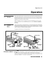
Components and functions are illustrated below.
)LJXUH %DVLF 3URMHFWRU &RPSRQHQWV
&RPSRQHQWV )HDWXUHV
Accessed manually (or via the keypad if a motorized zoom lens is present),
the lens barrel of a zoom lens (optional) rotates to adjust the size of the image
without moving the projector. Minimum and maximum image sizes depend on which
zoom lens is installed — see Section 5, Specifications.
=220 0LUDJH 8VHU·V 0DQXDO
23(5$7,21
Accessed manually via 2 “tabs” on the lens (or via the keypad if a motorized
lens mount is installed), focus adjusts the sharpness and clarity of the image at the
current throw distance.
)2&86 /(16 2))6(7 ² Accessed manually using the 2 front knobs (or via the keypad if a
motorized lens is present), vertical and horizontal offsets shift the lens and move the
image up or down and left or right. See Section 2, Installation and Setup for the
offset ranges for any given lens. These are also listed on page 5-1.
6+877(5 RSWLRQDO Closing the shutter blocks the lens internally and turns the
image to off. The shutter is controlled via a dedicated key on the keypad.
/$03 6,'( 3$1(/ For accessing the interior lamp door and replacing the lamp
module. NOTE: Lamp replacement requires a qualified service technician.
),/7(5 6,'( 3$1(/ Louvered grille for air intake. Remove to replace air filter.
&20326,7(69,'(2 ,1387 RSWLRQDO Accepts a composite video and S-Video
signal from devices such as VCRs. Requires optional video decoder module.
Accepts RGB and sync signals from devices such as computers, as well
as composite video, S-Video or YPbPr component signals.
5*% ,1387 Allows one or more projectors to
be remotely controlled by a computer or controller, and provides a communications
connection for Christie’s Marquee Signal Switchers.
56 6(5,$/ ,17(5)$&( :,7+ /223 7+528*+ Allows one or more projectors to
be remotely controlled by an RS-422 compatible computer or controller (such as the
Two-Way Controller accessory). RS-422 communications can travel greater distances
than can RS-232 communications, but require RS-422 compatible equipment.
56 6(5,$/ ,17(5)$&( :,7+ /223 7+528*+ 0LUDJH 8VHU·V 0DQXDO
23(5$7,21
$& /,1( &25' ,1387 The Mirage 2000 requires input power of 100-240 VAC,
50-60 Hz @ 9 amps (@ 100 V). The Mirage 5000 requires input power of 200-240
VAC, 50-60 Hz @ 8.5 amps (@ 200 V). Use the line cord provided with the projector.
See Section 5.
:$51,1*
'R QRW DWWHPSW RSHUDWLRQ LI WKH $& VXSSO\ LV QRW ZLWKLQ WKH
VSHFLILHG YROWDJH DQG SRZHU UDQJH 8VH WKH VSHFLILHG OLQH FRUG
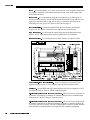
Two LEDs (light emitting diodes) located in the lower right
corner of the rear connector panel indicate projector "Status" (top) and "Power"
(bottom). During normal operation, the "Power" light is steady green and the "Status"
light flashes green each time a key is pressed or when the projector receives a serial
command. Use the following as a guide:
67$78632:(5 /('6 )LJXUH 5HDGLQJ WKH 6WDWXV /('V
NOTE: A steady red power light accompanied by a coded pattern of red and yellow
flashes from the status light indicates an internal system error. Consult the rear LCD
display for an explanation, and see 3.10, Error Conditions. Should the problem
persist, contact a qualified service technician available through your dealer.
5(027( :,5(' .(<3$' &211(&725 SLQ ;/5 For optional tethered remote
control of the projector.
%8,/7,1 .(<3$' Alternative location for entering commands. NOTE: If desired, the
keypad can be inverted by a qualified service technician. Contact your dealer.
/&' 67$786 ',63/$< ²
Visual feedback for monitoring projector activities and status.
The infrared (IR) sensors on the front and rear of the projector
receive infrared signals from the IR keypad for remote control of projector functions.
For proper operation make sure that these sensors are not blocked.
,1)5$5(' 6(16256 Emergency access for powering down the projector in the event of a
system failure. Insert a pen point or small screwdriver.
+$5' 5(6(7 0LUDJH 8VHU·V 0DQXDO
23(5$7,21
The keypad appears in three locations:
8VLQJWKH
.H\SDG
x
x
x
Built-in to the rear of the projector
Infrared (IR) Remote for tetherless control up to 100 feet away
Wired Remote (optional) tethered to the rear of the projector
While each keypad is identical in layout and provides complete control of the
projector, you may find one keypad more convenient than another for your specific
installation and application.
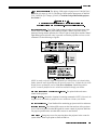
%XLOWLQ
The built-in keypad is located at the rear of the projector. An LCD window above
this keypad provides feedback regarding current status and activities of the projector.
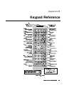
)LJXUH .H\SDG
0LUDJH 8VHU·V 0DQXDO
23(5$7,21
,5 5HPRWH
The IR Remote Keypad controls the projector by way of wireless communications
from a battery-powered infrared (IR) transmitter. Use the IR remote keypad the same
way you would use a remote keypad supplied with a TV or VCR. When making key
presses, point the keypad either toward the screen or toward the front or rear of the
projector. One of two sensors on the projector will detect the signals and relay the
commands for internal processing.
:LUHG 5HPRWH
³237,21$/³
The wired remote keypad connects to the 3-pin XLR jack via a 50 ft. cable. It is
recommended when:
x
x
x
the rear of the projector is inaccessible
the lighting conditions are unsuitable for proper IR transmission
you want to use a separate keypad for each projector in a group
NOTES: 1) For extra long distances and/or harsh environments, you may prefer to
use an optional remote Two-Way Controller to control the projector. For operating
details, please see the Two-Way Controller User’s Manual included with this
accessory. 2) Old VistaGRAPHX “Roadie style” keypads can be used with this
projector, but the )XQF key codes listed on the back are different and do not apply.
*XLGH WR .H\SDGV
Keep in mind the following guidelines:
Press keys one-at-a-time; there are no simultaneous key presses required.
For any key having an “*” ( 3RZHU , for example), hold the key for approximately 1
second in order to toggle the function with a single key press. For other keys (or
to use a “*” key in conjunction with 21 or 2)) ), a momentary press similar to
a mouse click is sufficient.
Press the “lightbulb key” to temporarily illuminate the backlight for the keys
without sending any other command.
,
, 21 , and 2)) repeat their “arrow” actions when held down. For
other keys, release and press again to repeat an action. In a network, pause
between adjustments to ensure that the last projector can “keep up” with the
commands.
If you press a key while the projector is busy with another action, such as during
a power-up, the key press may not take effect.
When you turn on the projector it begins operating at presentation level, displaying
an image from the most recently used source signal. The projector temporarily leaves
presentation level whenever you use the keypad to work with control settings, display
menus, or on-line help. For example, pressing 0HQX after startup displays the main
menu — presentation level is no longer active, although the image still appears in the
background. Press 0HQX again (or ([LW ) to return or leave the menu system and return
to presentation level.
.H\SDG &RPPDQGV
Specific keypad commands are explained below:
3RZHU
3RZHU 212))
Press and hold for approximately 1 second to turn the projector on or off with a
single key press. Or press 3RZHU followed immediately by 21 or 2)) if you want to
guarantee the correct toggle (useful if you are unsure of the present status).
NOTES: 1) Whenever the projector is turned off, the lamp cooling fans remain on for
about five minutes to cool the lamp. 2) It is a good idea to avoid turning a projector
0LUDJH 8VHU·V 0DQXDO
23(5$7,21
back on until it has been off for a few minutes. Hot re-strikes of the lamp may reduce
lamp life.
,QSXW
,QSXW Press ,QSXW to select the source connected to ,1387 on the projector (data input).
This is the same as entering ,QSXW
.
,QSXW
,QSXW Press ,QSXW to select the source connected to ,1387 on the projector (an optional
.
interface). This is the same as entering ,QSXW
,QSXW
,QSXW Press ,QSXW to select the source connected to ,1387 on the projector (composite
video). This is the same as entering ,QSXW
.
,QSXW
,QSXW Press ,QSXW to select the source connected to ,1387 on the projector (S-Video). This
.
is the same as entering ,QSXW
,QSXW
,QSXW
when you want to display from a specific source location, such as a
Press ,QSXW
switcher connected serially to the projector’s switcher port. The first digit represents
the number you have assigned to your switcher (usually 1-9, or “0” for one of the
four inputs on the projector). The second digit represents the switcher’s slot number
(1-9). For example:
,QSXW
= display data from switcher 1, slot 2.
NOTES: 1) Although you don’t need to use the input key unless a switcher is
connected to the projector, you can also use ,QSXW to access the four input “slots” on
as the first digit (representing the projector as the
the projector itself: use
as the second digit (the desired input slot number).
switcher), then , ,
, or
in combination with higher numbers is an invalid entry. 2) See 3.5, Using
Channels and Inputs for a detailed explanation of inputs.
NOTE: ,QSXW key behavior during a presentation depends on whether or not the
Display Channel List option is selected in the Preferences menu. You can choose to
have on-screen feedback when you press ,QSXW , or you may prefer to enter the desired
source location “blind”, i.e., without on-screen feedback. See Preferences later in
this section.
&KDQ
&KDQQHO
Press &KDQ to select a specific source setup (channel) defined and stored in projector
memory. Once you enter a 2-digit channel number (or, if there is a list displayed,
highlight it and press (QWHU ), the display will automatically change and update
according to the numerous setup parameters defined for that channel.
NOTE: &KDQ key behavior during a presentation depends on whether or not the
Display Channel List option is selected in the Preferences menu. You can choose to
use a scrollable list of channels when you press &KDQ , or you may prefer to enter the
desired channel number “blind”, i.e., without on-screen feedback. See Preferences
later in this section.
0LUDJH 8VHU·V 0DQXDO
23(5$7,21
6WE\
6WDQGE\
Press 6WE\ and hold for approximately 1 second to blank all display while keeping the
projector in a warmed-up and ready state. Or quickly press and release 6WE\ and
follow immediately by 21 or 2)) if you want to guarantee the correct toggle
(useful if you are unsure of the present status). Note that the lamp and electronics
remain ON in standby mode, even though the image turns to black and most
functions are disabled. To leave standby press and hold 6WE\ again (or use 6WE\ 2)) ).
Or simply press ([LW or 0HQX .
0HQX
0HQX
Press 0HQX to display the Main menu. A list of several options appears for access to
specific functions, such as Channel Setup or Image Settings. Press 0HQX again to
remove all menus and return to presentation level.
(QWHU
(QWHU
Press (QWHU to select a highlighted item, to toggle a checkbox (checked vs. unchecked),
or to accept a parameter adjustment and return to the previous menu or image.
([LW
([LW
Press
([LW
to return to the previous level, such as the previous menu.
NOTE: ([LW does not save changes within text editing boxes (including number
editing of a slidebars) or within pull-down lists. It acts as a “cancel” in these cases.
$UURZ .H\V
The arrow keys have a variety of functions depending on the situation. Some typical
uses are described below. See also Editing Text later in Section 3.
x
x
x
21
or
Use
or
to change a slidebar value—hold as desired for continuous
adjustment (note the adjustment increments and range depend on the
parameter being adjusted).
Use
or
to change to a different option within a pull-down list
without having to display the list first
Use
or
to jump between “pages”, such as in Help or lengthy pulldown lists.
Use the 21 or 2)) keys to navigate within a menu, pull-down list or text box, or to
increase or decrease the value in the second (bottom) slidebar of a double slidebar.
2))
You can also use 21 or 2)) in conjunction with certain toggle keys—i.e., those
including an asterisk symbol—to ensure a toggle only in the desired direction. When
turning the projector on, for instance, you may be too far from the projector to know
whether it is really off or if the shutter is merely closed. If you press 3RZHU and hold it
for approximately 1 second in hopes of turning the projector on, the projector will
actually turn off if the projector was already on. Instead, to avoid the risk of toggling
in the wrong direction, quickly press and release normally the function key you wish
to toggle (in this case 3RZHU ). Then immediately (within 2 seconds) press either 21
or 2)) as desired. The specific toggle will occur.
Toggle keys are labeled with an asterisk on the keypad. They are listed below:
0LUDJH 8VHU·V 0DQXDO
23(5$7,21
x
6KXWWHU
6KXWWHU
x
6WE\
+
+
3RZHU +
3RZHU +
0XWH +
0XWH +
26' +
26' +
6WE\
x
x
x
&RORU
+
+
21
= close the shutter (OPTIONAL)
= open the shutter (OPTIONAL)
21 = put the projector in standby mode
2)) = leave standby
21 = turn the projector on
2)) = turn the projector off
21 = hide the current menu
2)) = show the current menu
21 = turn the menu system on
2)) = turn the menu system off
2))
&RORU
Press &RORU to adjust the color saturation level, i.e. the amount of color in a video
image. Lower settings produce less saturated colors — a setting of “0” produces a
black and white image, for example. If the color level is too high, colors will be
and
until the desired color saturation
overpowering and unrealistic. Use
&RORU
level is displayed. The
key has no effect when the ADP option is used.
7LQW
7LQW
Press 7LQW to adjust the red/green color hue for true color reproduction of NTSC video
signals or HDTV signals. For best results, adjust tint while displaying a proper
external test pattern from the source — otherwise, it is recommended that tint remain
and
until the desired tint is displayed.
at its default setting. Use
'HWDLO
'HWDLO
Press 'HWDLO to adjust the sharpness of a video image (it is of limited use for nonvideo). Use
and
until the display is as sharp as desired, keeping in mind
that any level of detail above 3 will also introduce a certain degree of noise in the
image. Set below 3 to filter the signal and remove noise from a noisy source.
&RQW
&RQWUDVW
and
until you
Press &RQW to change the amount of white in your images. Use
reach the desired level of contrast—for best results, start low and increase so that
whites remain bright but are not distorted or tinted, and that light areas do not
become white (i.e., are “crushed”). Conversely, low contrast causes dim images. See
3.6, Adjusting the Image (Image Settings subsection).
%ULJKW
%ULJKWQHVV
Press %ULJKW to increase or decrease the amount of black in the image. Use
and
until you reach the desired level of contrast—for best results, start high and
decrease so that dark areas do not become black (i.e., are “crushed”). Conversely,
high brightness changes black to dark gray, causing washed-out images. See 3.6,
Adjusting the Image (Image Settings subsection).
9RO
9ROXPH
Non-functional.
3URM
3URMHFWRU
Press 3URM when you want to access a specific projector within a network or if you
simply need to see if the local projector is listening. The number appearing in the
“Enter Number” window indicates which projector is currently listening to
0LUDJH 8VHU·V 0DQXDO
23(5$7,21
commands, and will match the projector number that has been defined in its
Preferences menu.
The “Projector” checkbox (read-only) shows whether or not the projector physically
connected to a keypad is listening to commands from that keypad. A checkmark
means that connected projector is listening; if there is no checkmark, you are
communicating with a different projector.
To use a specific projector, enter the 3-digit number assigned to the projector you
want to use. Press (QWHU to select, press ([LW to cancel. If you switch to a projector
other than the one you are currently using, the checkmark will be deleted.
To broadcast to multiple projectors, press 3URM and then 3URM again without entering a
projector number. Keypad commands will then affect all projectors present.
NOTES: 1) The "Broadcast Keys" option in the Communications menu must be
selected for only one (any) projector in a serial network. The keypad in use must be
OFF (disabled) for the remaining projectors. See 2.10. Keypad Protocols and
Conversion, and 3.7, Adjusting System Parameters and Advanced Controls.
3L[HO
3L[HO
Press 3L[HO to access the pixel tracking and pixel phase double slidebar. Adjust pixel
tracking first: use
and
to increase or decrease the frequency of the pixel
sampling clock to correct consistency of the image. For proper phase, use 21 and
2)) to increase or decrease pixel phase so that any shimmer disappears and the
image is stable throughout. See 3.6, Adjusting the Image (Size and Position
subsection) for a complete explanation of tracking and phase.
3RVLWLRQ
3RVLWLRQ
Press 3RVLWLRQ to move the image using the double slidebar. At the slidebar, use
and
to move the image left or right, use 21 and 2)) to move the image up or
down.
/HQV
/HQV 237,21$/
NOTES: 1) Requires a motorized lens. In non-motorized projectors, adjust the lens
manually for proper focus, zoom and offsets as described on page 2-2. 2) For full
details regarding use of motorized lens functions, refer to 2.8, Zoom, Focus and
Lens Offset.
Press /HQV to access remote
motorized control of
horizontal/vertical offsets, focus
and zoom, and other related
functions in the Lens Control
menu. All slidebars can be
and
, or
adjusted with
set with a specific value entered
from the keypad.
)LJXUH /HQV &RQWURO 0HQX /HQV NOTE: Since the direction of lens
travel affects the final true position of the lens, setting a lens position (focus, zoom or
an offset) to a specific value may cause the lens to reverse its direction of travel,
depending on its starting point, so that it approaches the setting from the necessary
0LUDJH 8VHU·V 0DQXDO
23(5$7,21
direction. Any even-numbered setting is approached from above (the slidebar values
will decrease), any odd-numbered setting is approached from below (the slidebar
value will increase). This ensures accurate lens positioning.
)2&86 Adjust the image clarity. If focus is not uniform throughout the image, bore
sight is likely poor. Contact your dealer for service.
=220 Enlarge or shrink the image (note: requires a non-VistaGRAPHX zoom lens).
+25,=217$/ 2))6(7 Shift the lens and image left or right. Note that slidebar values
will not reach extremes of 0 or 9999. This is normal.
9(57,&$/ 2))6(7 Shift the lens and image up or down. Note that slidebar values
will not reach extremes of 0 or 9999. This is normal.
,17(//,*(17 /(16 6<67(0 Enable “Intelligent Lens System” (ILS ) to add the 4
lens positions—focus, zoom, horizontal and vertical offset—to the current channel
settings recorded in projector memory (see 3.5, Using Inputs and Channels if you are
unfamiliar with channels). This feature is particularly useful if you are using sources
with differing aspect ratios, such as anamorphic vs. 5:4. When switching to and from
such displays, the
lens will
automatically
move to the last
defined position
for each channel,
quickly
optimizing the
display for focus,
zoom and offsets.
)LJXUH /HQV 6HWWLQJV DQG WKH ,/670
ILS is a global
function—any
lens settings you subsequently define for other channels will be recalled whenever
you use those channels. Delete the checkmark if you want to use consistent zoom,
focus and offset settings for all channels—the lens will not move unless you re-adjust
a lens setting.
TM
TM
For full details regarding optimization of ILS performance, refer to 2.8, Zoom,
Focus and Lens Offset.
TM
Select “Calibrate Lens” to ensure that the physical mid-point for
each of the four lens functions is defined as such in software, and that lens mount
movements remain accurate to this reference. Regular calibration can correct for
slight eventual mechanical “drifting” of movements over time. It is particularly
recommended whenever the projector is bumped or subjected to vibration, and it is
required whenever a new lens is installed and after certain service procedures.
&$/,%5$7( /(16
During calibration, the lens mount will move in various directions for approximately
30 seconds, detecting the center of focus and offset ranges and the extremes for
zoom. A small “Lens Calibrating” message appears on screen during calibration.
Calibration is complete when lens mount movement stops (and the menu
reappears)—note that the lens returns to the previous settings.
NOTES: 1) Calibration with a fixed lens installed causes the zoom calibration to
time-out, possibly delaying the completion of calibration by a few seconds. This is
normal. 2) If calibration with a zoom lens installed takes longer than approximately
0LUDJH 8VHU·V 0DQXDO
23(5$7,21
30 seconds to complete, make sure the focus motor is engaged as described in 4.5,
Replacing the Lens.
This option removes most vertical and horizontal offset and returns
the lens to the approximate center of the lens opening—the image will be fairly wellcentered on this axis. Note that if centering remains significantly “off”, lens mount
bore sight is likely poor. Contact your dealer for service.
&(17(5 /(16
6KXWWHU
6KXWWHU
237,21$/ )81&7,21
If your projector has a mechanical lens shutter (a.k.a. dowser) added, press and hold
6KXWWHU for approximately 1 second to toggle the shutter closed or open with a single
key press (this also blanks the image electronically). Or quickly press and release
6KXWWHU and follow immediately with
21 or
2)) if you want to guarantee the correct
toggle (useful if you are unsure of the present status). Close the shutter whenever you
want to mute all display yet maintain access to projector functions. Open the shutter
to regain the display. With no shutter installed, 6KXWWHU still blanks the image
electronically, but the blanking is not quite as black.
NOTES: 1) The status of the shutter is shown in the LCD window on the rear panel of
the projector. 2) Upon power-up, the shutter is open. 3) The lamp remains on.
0XWH
0XWH
0XWH temporarily turns the current menu on or off—press and hold 0XWH for
approximately 1 second to toggle with a single key press. Or quickly press and
release 0XWH and follow immediately with 21 or 2)) if you want to guarantee the
correct toggle (useful if you are unsure of the present status). With either method, a
small message appears on screen while the menu is muted.
)XQF
)XQFWLRQ .H\
From presentation level, press )XQF followed by a 2-digit number to enable a specific
will display only red and green
color or colors in the display. For example, )XQF
data, )XQF
will display all colors data. The list of available color combinations is
shown below and also appears on the back of the IR remote keypad. Color enabling
can also be accessed through the menu system rather than these shortcuts.
)XQF
)XQF
)XQF
)XQF
)XQF
)XQF
)XQF
= Red
= Green
= Blue
= Red and Green
= Green and Blue
= Red and Blue
= All colors ( ([LW does the same thing)
NOTE: Once )XQF is pressed in presentation level, the projector will not respond to
non-numeric entry until 2 digits have been entered or until 5 seconds of inactivity
have elapsed.
Use of the )XQF key within the menu system is noted with the appropriate topic
elsewhere in Section 3. For example, press )XQF in the Channel Setup menu to enable
deletion or copying of a channel.
0LUDJH 8VHU·V 0DQXDO
23(5$7,21
26'
26' 2QVFUHHQ GLVSOD\
Press and hold 26' for approximately 1 second to toggle menus on or off (i.e.,
visible or invisible). Or press 26' followed immediately by 21 or 2)) to
guarantee the correct toggle direction (useful if you are unsure of the present status).
Note that invisible menus are fully functional.
NOTES: 1) With OSD on, you can still mute menus, error messages, slidebars, etc.
with the appropriate setting in the Preferences menu. 2) The status of the 26' key is
displayed in the LCD window on the rear panel of the projector.
+HOS
+HOS
Press +HOS for detailed information about any current menu and highlight. Press +HOS
again to exit. From presentation level, press +HOS to access the General Help menu
consisting of Using Help, Setup, Keys, Source (Input) Selection, Stat/Pwr LEDs and
Using 3D. Press ([LW to leave General Help and return to presentation level.
7HVW
7HVW
Press 7HVW to display one of the available test patterns. Press 7HVW again to display the
next available pattern in the sequence. 7HVW will exit after the last pattern, or press ([LW
at any time to remove the current test pattern from the screen and return to
presentation level.
NOTE: For a complete list of available patterns, see the Advanced menu description
later in Section 3.
.H\SDG RSHUDWLQJ VHWWLQJV SURWRFROV
The remote keypad and the optional wired keypad both store keypad operating
settings (called protocols) in memory. In some advanced applications, such as when
you want to use two separate keypads to control two projectors independently, you
may want to override the original protocol set at manufacture (which is "A or B") for
one of the keypads. See section 2.10, Keypad Protocols and Conversion for complete
instructions.
1DYLJDWLQJWKH
0HQXV
Most of the controls for the projector are
accessed from within the projector’s menu
system. There are several groups of related
functions, with each group selectable from the
Main menu as shown at right. Press 0HQX at any
time to display the Main menu.
On the keypad, either enter the number
corresponding to the function menu you wish to
for the Image Settings menu,
access, such as
)LJXUH 0DLQ 0HQX
or use the
keys to highlight the desired
option and press (QWHU . The function menu you
selected will then appear. If you select “Auto Setup”, this will not activate a separate
function menu but rather begin an automated process of optimizing critical display
parameters such as size, position, pixel tracking, etc.
Once you have a function menu displayed, navigate in a similar manner—enter a
to move the highlight
menu option number for any numbered option, or use
0LUDJH 8VHU·V 0DQXDO
23(5$7,21
and press (QWHU at the desired option. Extra long menus have a scroll bar on the right–
use the arrow keys to see the remainder of the menu. Items that are locked out or do
not pertain to the current action appear dimmed and cannot be selected.
NOTES: 1) If there is no signal present, all source-dependent adjustments are
disabled. 2) After 15 minutes of inactivity, the projector leaves the menu system and
returns to the presentation. 3) The Status menu is read-only.
When finished with a function menu, do one of the following:
2QOLQH +HOS
x
Press
([LW
x
Press
0HQX
to return to the previous screen
to leave the menu system and return to the presentation
If at any time you are uncertain what to do next, press
+HOS
to display detailed
information about the current menu or highlighted option. A scroll bar appears on the
right-hand side of a help window if there is additional text–use the arrow keys to
scroll. Press +HOS again to exit.
From presentation level, press +HOS to access general Help Topics. Scroll as necessary
within a topic. Press ([LW to return to your presentation.
)LJXUH $FFHVVLQJ *HQHUDO +HOS 7RSLFV
At the bottom of some menus, a line of hint text also appears.
7LPHRXWV
Whenever the projector is not at presentation level, such as when there is a slidebar,
menu, message or test pattern displayed, you have limited time in which to make a
keypad entry before the projector returns to presentation level and the graphic
disappears. These time-outs vary depending on the current display, as shown in the
following chart:
0LUDJH 8VHU·V 0DQXDO
23(5$7,21
7,0(2876
8VLQJ 6OLGHEDUV DQG
2WKHU &RQWUROV
6OLGHEDU IURP SUHV
VHFRQGV
6OLGHEDU IURP PHQX
PLQXWHV
/DPS 7LPHU 0VJ
VHFRQGV
&KDQQHO HQWU\
VHFRQGV
2WKHU
PLQXWHV
Most of the function menus allow you to change settings by using slidebars,
checkboxes, and pull-down lists. To select a slidebar, toggle a checkbox status, or
view a pull-down list, do one of the following within the function menu:
x
x
x
x
Enter the menu option number corresponding to the setting you wish to
for Vertical Stretch in Size & Position menu).
change (for example, press
Or move the highlight to the desired parameter and press (QWHU .
Or move the highlight to the option desired and press
or
.
Or bypass menus entirely and use a single key to immediately access an
adjustment (note: applies only to options having their own key, such as Color,
Tint, Detail, Contrast, Brightness, Pixel and Position).
Once selected, change the setting as desired (see below) and press
return to the current function menu.
(QWHU
to save and
The current value for a given option,
such as size or vertical stretch, appears to the left of its slidebar
icon. This number may express a percentage or specific units (such as pixels, degrees
or
to gradually adjust the
Kelvin, etc.), depending on the option. Press
setting up or down—both the number and the length of the bar change accordingly
(for continuous adjustment, hold down the desired arrow key). Or press (QWHU to
activate a slidebar text box for specific number entry via the keypad, then press
or
and (QWHU to save (or press ([LW to cancel).
6OLGHEDUV LQ PHQXV 'RXEOH VOLGHEDUV In double
slidebars, such as the pixel
tracking/pixel phase double
slidebar, adjust the top slidebar
or
as desired.
with
When you have finished with the
top slidebar (whether changed or
not), adjust the bottom slidebar
with 21 or 2)) . When you are done, press ([LW to return to your presentation. For
fast continuous adjustments, hold down the desired arrow key.
For quick access, you can often use a slidebar (or double
slidebar) without traveling the menu system. For example, simply press &RQW to
immediately display the same contrast slidebar accessed with the &RQWUDVW option in
the Image Settings menu. Direct slidebars are listed below.
´'LUHFWµ VOLGHEDUV 0LUDJH 8VHU·V 0DQXDO
23(5$7,21
/,67 2) ',5(&7 6/,'(%$56
+3RVLWLRQ RU 93RVLWLRQ
3RVLWLRQ
3L[HO 7UDFNLQJ RU 3KDVH
3L[HO
9ROXPH
&RQWUDVW
&RQW
%ULJKWQHVV
%ULJKW
&RORU
&RORU
7LQW
'HWDLO
7LQW
'HWDLO
Use the arrow keys to adjust a direct slidebar, or press (QWHU and enter a specific
number from the keypad , then (QWHU or
or
to save ( or ([LW to cancel).
([LW
When you are done, press
to save and return to your presentation.
NOTES: 1) You can still adjust a direct slidebar as usual if the menu display is
turned off (see 26' or Preferences menu) — the slidebar just won’t be visible. 2) A
direct slidebar disappears if it is not used within 5 seconds.
&KHFNER[HV Conditions are present if its adjacent checkbox contains a checkmark.
To toggle the checkbox, simply highlight and press (QWHU , or highlight and use
to
check and
to uncheck. For a checkbox that is
numbered, simply enter the number of the option to toggle
the checkbox.
To see a pull-down list of options available for a given parameter
labeled with a W, you can:
3XOOGRZQ OLVWV ²
x
x
Highlight it and press (QWHU
Or enter the menu option number.
Use 21 or 2)) keys to navigate up and down within the list (the current choice is
noted with a small ). Press (QWHU to choose an option from the list, if desired.
)LJXUH ([DPSOH RI 3XOO'RZQ /LVW
Or, of you prefer to quickly scroll through a list without first pulling it down,
highlight the option and use
or
. Press (QWHU when the desired choice appears.
or
to jump between “pages” in an extra long pull-down
NOTES: 1) Press
list. 2) Press ([LW while in a pull-down list to cancel any change.
0LUDJH 8VHU·V 0DQXDO
23(5$7,21
(GLWLQJ 7H[W
To enter or edit text, highlight the desired parameter
(such as a channel name) and press (QWHU to activate its adjacent edit window. Any
previously entered text is displayed with its first character highlighted in a square
cursor, signifying that this character is ready for editing.
$&7,9$7( 7+( (',7 :,1'2:
Press
to move the cursor backwards as desired.
1$9,*$7( :,7+,1 7+( (',7 :,1'2:
to move the cursor forward or
To edit a highlighted
and
character, use
to scroll through
the alphabet, numbers, spaces and
punctuation available. When the character
to select it—
you need appears, press
the cursor will move to the next character of
current text, if present. Note that you can
also enter a number directly from the
keypad—it will be accepted and the cursor
will move on.
(',7 $ &+$5$&7(5
)LJXUH (QWHULQJ 7H[W
To insert a space at the cursor location,
. To delete a highlighted character (or space), press )XQF
.
$'' 25 '(/(7( $ &+$5$&7(5 25 63$&(
press
)XQF
35(66 (QWHU :+(1 ),1,6+('
press
(QWHU
NOTE: Press
text.
(GLWLQJ 1XPHULFDO 9DOXHV
To accept the edits and move out of the edit window,
.
([LW
at any time to cancel changes and return to the previously-defined
Enter numbers directly from the keypad in order to specify numbers representing
projectors, channels (source setups), switchers, or slots. As each digit is entered, it is
displayed and the cursor moves on. Note that channel numbers are always defined
with 2 digits—for example, if you enter only a single digit (like “7”) for a channel
number, the channel will automatically be defined as “07”. Use “07” to utilize this
channel.
NOTES: 1) Once you enter the first digit, this digit replaces all old digits. 2) If you
press any non-numbered key, the number entered up to that point is accepted and
updated as the new value. 3) Press ([LW to cancel editing of numerical values.
0LUDJH 8VHU·V 0DQXDO
23(5$7,21
NOTE: See Section 2, Installation and Setup, for a full explanation of how to
connect a variety of sources to the projector.
8VLQJ,QSXWV
DQG&KDQQHOV
'R , 6HOHFW DQ ,QSXW
2U D &KDQQHO"
The projector stores and automatically recalls up to 99 different channels (source
setups) for a variety of inputs. This memory feature allows you to define and
conveniently use a wide variety of customized setups rather than having to repeatedly
re-configure the projector for different presentations. Each physical source (i.e.,
input) can have several different channels associated with it.
,1387 An input simply describes a physical location for an incoming signal
connection. These connections are always either on the projector itself (one of the
four inputs at the rear of the projector) or on any switcher connected to the
projector’s switcher port. ,QSXW describes the source signal according to two specific
criteria only—to which switcher it is connected and to which slot it is connected—
and is identified by a 2-digit number entered on the keypad. The first digit specifies
the switcher (0-9), the second specifies the slot (1-9). Note that the projector is
always considered “switcher #0”.
(;$03/(6
,QSXW
,QSXW
= use source connected to switcher #1, slot #3
= use source connected to the projector, slot #1 (i.e.,
,QSXW
)
You can switch to an input in either one of two ways. Pressing the appropriate direct
key — ,QSXW , ,QSXW , ,QSXW , or ,QSXW — is a quick and seamless way to display from one
of the four inputs connected at the rear of the projector. Or, if your projector has a
switcher connected to it at the 6:,7&+(5 port, press the general ,QSXW key and enter
the 2-digit number representing the switcher and slot location for the desired signal
(note there is no on-screen feedback for entering the numbers).
Regardless of which method you use to select a source/input, the image will be
displayed according to the following:
If it is the first time you have used the source/input (or if you used the input but did
not define a channel by adjusting anything ), the projector will recognize the new
input signal based on its frequencies and polarities, and will automatically display an
image according to default settings for such a signal. Note that a graphic source will
resize into a full-screen image, whereas video or HDTV sources will resize only as
much as possible while maintaining their aspect ratio.
If you used the source once before and changed a display parameter such as
contrast, V-Position etc., then a channel was automatically created and still exists in
projector memory (see below). Using an ,QSXW key will automatically recall this
channel—and all its setup parameters—and update the display accordingly.
If more than one channel exists for the input, the image will be displayed according
to the setup parameters for the first channel with matching characteristics.
A channel is a collection of measurements, locations and settings that
tailor a display to your specific needs. Since source types and applications can vary
greatly, you will likely want to adjust and define a wide variety of parameters, such
as brightness, contrast, tint, size, etc., in order to customize and optimize the display
coming from a particular source. For example, the display settings you choose for a
VCR source may be very different from those you choose for a high resolution
computer source, or one signal may simply vary from another signal used earlier
&+$11(/ 0LUDJH 8VHU·V 0DQXDO
23(5$7,21
through the same input location. Once you have adjusted a display parameter, such as
pixel tracking or contrast, all current settings are collectively stored in the projector's
. You can have numerous distinct
memory as a unique 2-digit channel, such as
channels available for the same input, any of which can be selected by using the &KDQ
key on the keypad followed by the 2-digit channel number.
NOTE: The &KDQ key may display a channel
list or not, depending on what you have
defined within the Preferences menu (see
Preferences later in this section). Shown at
right is a sample channel list available from
&KDQ .
In order to use channels ( &KDQ on the keypad),
you must first create them. See below.
&UHDWLQJ D 1HZ To use a new source with the projector, a new
&KDQQHO /LVW &KDQ &KDQQHO
channel must be added to projector memory
³ $8720$7,& ³
so that the projector will respond properly to an input signal from that source in the
future. A new channel can be created automatically, as described here, or it can be
copied from an existing channel and then edited as necessary (see Copying or
Deleting Channels later in this section).
When you select a direct input (press ,QSXW or ,QSXW , ,QSXW , ,QSXW or ,QSXW ), the existing
channels in the projector are searched for matching input and signal parameters. If no
match to the incoming input signal is found in the currently defined channels, a new
channel is temporarily created based on factory-defined defaults for this signal. The
channel number assigned to this channel is the lowest available number from 01-99.
NOTES: 1) An automatic channel will be discarded unless one or more of its
parameters are changed, and will not appear in the Channel List (see below). 2) If
two channels have the same distinguishing source characteristics except for the
reversal of sync connectors (i.e., H-sync and V-sync, are switched), they are still
defined as distinct channels. 3) You cannot define a new channel without a signal
present.
If the incoming signal does match an existing channel, the image will be set up and
displayed as usual according to the parameters currently defined for that channel.
You can normally select a channel at any time by pressing &KDQ
(see right). If you want to prevent a channel from appearing in this list, you must edit
the channel as described
in Channel Edit later in
this section. Such a
channel can still be
selected by entering its
number as shown at right.
86,1* $ &+$11(/
NOTES: 1) The current
channel is highlighted
upon entering the
Channel List, or, if this channel is not displayed in the list, the first channel in the
list is highlighted. 2) Channels created automatically do not appear in the Channel
List unless a parameter has been changed.
0LUDJH 8VHU·V 0DQXDO
23(5$7,21
:KDW &KDQQHOV All available channels are listed in the Channel Setup menu, which describes how
$UH 'HILQHG 6R )DU"
each channel can be accessed and which serves as the gateway for editing, copying
and deleting channels.
From the presentation
level press 0HQX to
display the Main menu.
To display the Channel
Setup menu, press , or
move the highlight to the
Channel Setup option and
press (QWHU . The Channel
Setup menu will appear
(see sample at right),
with the active channel
highlighted.
)LJXUH $OO &KDQQHOV $SSHDU LQ WKH
&KDQQHO 6HWXS 0HQX
As shown in Figure 3.10, this menu
lists all channels defined so far and indicates how they are connected to the projector.
The far left column contains current channel numbers defined. The values in the far
right columns indicate horizontal and vertical frequencies—if a name has been
defined for this channel, it appears here instead. Other columns contain details
pertaining to each channel setup, such as its switcher number, slot location, a variety
of icons indicating access to the channel, and an abbreviated description of each
signal type. See Editing a Channel Setup for details.
:+$7 $33($56 ,1 7+( &+$11(/ 6(783 0(18"
Either channel list, whether the &KDQ key list or the Channel Setup
menu, identifies signal types in a shortened form as defined below. These descriptors
indicate what signal information the projector used to identify a match for a given
channel, and are preceded by either an “i” (interlaced signal) or “p” (progressive
signal). See Table 3.1.
6,*1$/ 7<3( ³
7DEOH $EEUHYLDWLRQV IRU 6LJQDO 7\SH
$EEUHY
6LJQDO 7\SH
:+
&RPSRVLWH ZLUH RQ +& LQSXW
:9
&RPSRVLWH ZLUH RQ 9 LQSXW
6*
6\QFRQJUHHQ
65
6\QFRQUHG
:
6HSDUDWH +9
:5
6HSDUDWH +9 VZDSSHG
69LG
69LG
&9LG
&RPSRVLWH 9LGHR
/+
7UL/HYHO RQ +& LQSXW
/9
7UL/HYHO RQ 9 LQSXW
/*
7UL/HYHO RQ JUHHQ
(/+
(XURSHDQ 7UL/HYHO RQ +& LQSXW
(/9
(XURSHDQ 7UL/HYHO RQ 9 LQSXW
(*
(XURSHDQ 7UL/HYHO RQ JUHHQ
'LJ
'LJLWDO
0LUDJH 8VHU·V 0DQXDO
23(5$7,21
If you have more than a handful of channels, use
channels not visible in this initial display.
and
to see the remaining
To copy, delete or edit any of the channels listed in the Channel Setup menu,
highlight the desired channel and do one of two things:
x
x
&RS\LQJ RU
'HOHWLQJ &KDQQHOV
Press )XQF if you want to copy the selected channel or delete this or other
channels. See Copying or Deleting a Channel below.
Press (QWHU if you want to edit channel setups (i.e., non-image related
parameters) for the selected channel. See Editing a Channel Setup,
below.
, highlight the desired channel in the Channel Setup menu, then
to go to the Channel Copy/Delete submenu. Select “Copy” and press
press
(QWHU —a new channel will be created. It is identical to original, which still remains,
but it is identified with the next available number from 01-99. If you change your
mind and do not want to copy the current channel, press ([LW to cancel and return to
the previous menu. Copying channels is a quick method for creating numerous
channels, each of which can then be edited and adjusted for a variety of presentations
in the future.
72 &23< $ &+$11(/
)XQF
)LJXUH &RS\LQJ $ &KDQQHO
, highlight the desired channel in the Channel Setup menu,
then press )XQF to activate the Channel Copy/Delete submenu. Select “Delete” and
press (QWHU —a confirmation window will appear to make sure that you really want to
delete this channel.
72 '(/(7( $ &+$11(/
)LJXUH 'HOHWLQJ D &KDQQHO
, highlight any channel in the Channel Setup menu
and press )XQF to go to the Channel Copy/Delete submenu. Select “Delete Unlocked
Only” and press (QWHU to delete all unlocked channels. Or select “Delete All Channels”
72 '(/(7( 08/7,3/( &+$11(/6
0LUDJH 8VHU·V 0DQXDO
23(5$7,21
to delete all channels, even those that are locked. In either case, the current channel
will remain but will be redefined from projector defaults.
NOTE: For any deletion, a confirmation box appears to make sure that you really
want to delete. Select “Cancel” (default) if you don’t want to delete after all.
(GLWLQJ D &KDQQHO 6HWXS The basic setups that describe how and where a channel can be accessed are listed in
the Channel Setup menu. These channel setups can be edited at any time in the
Channel Edit submenu.
&+$11(/ (',7 ³ 67(3 From the presentation level press
0HQX
to display the main menu. To display the
Channel Setup menu, press , or move the highlight to the Channel Setup option
and press (QWHU . The Channel Setup menu will appear.
&+$11(/ (',7 ³ 67(3 To edit parameters shown in the Channel Setup menu, select the relevant channel and press
(QWHU .
The Channel Edit menu will appear similar to the sample shown in Figure 3.13.
)LJXUH &KDQQHO (GLW 0HQX 6$03/(
&+$11(/ (',7 ³ 67(3 If desired, edit the following channel setups in the Channel Edit menu:
x
&+$11(/ 1$0( An alpha-numeric label can be defined and/or changed
here. Channel names can be up to 12 characters in length.
x
A channel number from 01 to 99 can be changed
here. NOTE: If you enter a channel number that already exists, a dialog
message appears indicating that this number is already in use–assign a
different channel number.
x
6:,7&+(5 180%(5 ´0” represents the projector itself. Or, if the input
source is connected to a switcher, the default will be the lowest switcher
number available (from 1-9)–change here as desired.
x
1 ( ,QSXW ), 2 ( ,QSXW ), 3 ( ,QSXW ), or 4 ( ,QSXW ) for projector inputs, or
current slot number (1-9) if the source is connected to a switcher.
&+$11(/ 180%(5
6/27
x
/2&.('
x
,1 0(18
If checked, all of the image settings for this channel are disabled.
If unchecked (default), all available image settings can be adjusted as
desired. You cannot use Auto Setup with a locked channel.
If checked (default, except for automatically defined channels
with unchanged parameters), this defined channel will then appear in the
list available when &KDQ key is pressed. If unchecked, the channel must be
accessed via &KDQ on the keypad or via the Auto Source function. NOTE:
0LUDJH 8VHU·V 0DQXDO
23(5$7,21
On-screen display of the channel list is an option that must be set in the
Preferences menu.
x
x
x
$GMXVWLQJWKH
,PDJH
If checked, (default), the projector can automatically
locate this channel when an incoming input signal matches. If not
checked, the projector can locate the selected channel only when it is
directly selected via &KDQ on the keypad—and a change in input signal will
not result in a channel change.
$872 6285&(
Select this option to see or change Channel Edit
settings for the previous channel in the Channel Setup list.
35(9,286 &+$11(/
1(;7 &+$11(/ Select this option to see or change Channel Edit settings
for the next channel in the Channel Setup list.
Most options for image adjustments can be accessed through two menus: Size and
) and Image Settings ( 0HQX
), both of which are listed in the Main
Position ( 0HQX
menu. While in either of these two menus, you can change settings affecting the
image from the current channel by working with the appropriate slidebars,
checkboxes and pull-down lists. ([LW will always return to the previous menu (or to
the presentation, if from the Main menu) and accept any changes you may have
made.
From your presentation, you can access any of the individual options in these menus
by pressing 0HQX followed by the appropriate two-digit number representing their
location in the menu system. For example, press 0HQX
to quickly access the
“color temp” option in the Image Settings menu.
Note that for certain options, you may prefer to use a “direct key” from presentation
level to go directly to a particular option rather than traveling through the menu
system at all (note: this is not available for all display parameters). For example,
press &RQW to access the “contrast” slidebar immediately. Press ([LW to return to your
presentation.
NOTE: 1) To hide the “direct” slidebars only, make sure the Display Slidebars
option in the Preferences menu is unchecked. 2) To hide the entire menu system
from view, toggle the on-screen display OFF: press and hold the 26' key.
$XWR 6HWXS If you want the projector to quickly set up the image for you, select “Auto Setup”
from the Main menu. A confirmation box will ask if you really want to continue, in
which case display parameters listed in the Table below will be set for you. An “Auto
Setup” can save time in setting up an image, then you can make further adjustments
as desired. You must have an unlocked channel present to use Auto Setup.
:KDW DQ ´$XWR 6HWXSµ 'RHV
0LUDJH 8VHU·V 0DQXDO
237,0,=(6
6(76 72 '()$8/7
3L[HO 7UDFNLQJ
3L[HO 3KDVH
6L]H
9HUWLFDO 6WUHWFK
3RVLWLRQ
,QSXW /HYHOV LI DQDORJ VRXUFH
&RQWUDVW %ULJKWQHVV
$XWR ,QSXW /HYHO RII
%ODQNLQJ
'HWDLO LI YLGHR VRXUFH
)LOWHU
/XPD 'HOD\
23(5$7,21
,PDJH 6L]H DQG 3RVLWLRQ
The Size and Position menu allows you to
increase or decrease the size of your
image, change its proportion (aspect
ratio), move the image to a specific area
of the screen, and refine other related
parameters. Use Size and Position
controls to match the image precisely to
the screen size and aspect ratio needed for
your application.
Refer to "Using Slidebars and Other
)LJXUH 6L]H DQG 3RVLWLRQ 0HQX
Controls" (earlier in this section) if you
need help using any of the following slidebars or pull-down lists to alter your image.
Changes made to the Size and Position menu are applied immediately and are saved
when you exit the menu (press ([LW or 0HQX ).
5HVL]H 3UHVHWV
Use Resize Presets to quickly
display an image in its native
resolution (including
anamorphic) or to
automatically resize an image
to closely fit the screen. The
value for Size, Position and
Blanking parameters
(described later) will, in turn,
change as necessary without
your having to set them manually.
)LJXUH 5HVL]H 3UHVHWV 6XEPHQX
:+$7 ,6 7+( 352-(&725·6 '()$8/7" When displaying a new source, by default
your image will fill the screen as fully as possible for the type of source present. See
Select “Default” below.
The “Custom” descriptor automatically appears in the
Size and Position menu when any of the values for Size, Vertical Stretch, H-Position,
V-Position or Blanking do not correspond to those for a preset. It is not an option in
the Resize Presets pull-down list.
:+(1 ´&86720µ $33($56
x
6(/(&7 ´'()$8/7µ (default) for most images. This option will center and display
your image as large as possible for the present source as described below:
9
9
9
9
A graphic image will resize to fill the screen, regardless of its original
aspect ratio. For example, 1024 x 768 becomes 1280 x 1024.
A video image will resize to fill the screen while still maintaining its
aspect ratio (assumed to be 4:3).
An HDTV wide-screen (16:9) image will resize to fill the screen
horizontally while maintaining its 16:9 aspect ratio—i.e., there will be
black borders at top and bottom, commonly called “letterboxed”.
A non-HDTV anamorphic (16:9) image, typical of DVDs, will be
stretched vertically.
So with the exception of HDTV (16:9), the “Default” setting produces an aspect
ratio that is either almost or exactly 5:4, as shown in the following examples.
0LUDJH 8VHU·V 0DQXDO
23(5$7,21
x 6(/(&7 ´12 5(6,=,1*µ to display the image in its native resolution, which may be
smaller or larger than the native resolution of the projector. All Size, Vertical
Stretch, H-Position, V-Position or Blanking values will change accordingly. For
example, for a source with a native resolution of 800 x 600, “No Resizing” will
center a small image within a black border. Conversely, an HDTV image is wider
than both 1024 and 1280 and will be cropped on the sides—or, in the case of
“1080i” HDTV, cropped at top and bottom too. With “No Resizing”, signals with
non-square pixels, such as video connected to ,1387 or ,1387 , produce
distorted images that are too tall or too wide. See below.
NOTE: 3D images are displayed with No Resizing only.
x 6(/(&7 ´)8// 6&5((1µ to use all pixels (1280 x 1024)
for displaying the image, regardless of source or
original aspect ratio. See right.
x 6(/(&7 ´$1$0253+,&µ to display an entire non-
HDTV “wide screen” (anamorphic) image in its native
16:9 aspect ratio. Known as letterbox, the image will fill
the screen from left-to-right, but will not use all vertical
pixels available (top and bottom will be black). If you
do not choose “Anamorphic” when a non-HDTV
anamorphic image is present, the default image will be
stretched vertically, characterized by obvious distortion
and “thin people”.
NOTE: Use “Anamorphic” for regaining a 16:9 display of
non-HDTV anamorphic sources only (typically found on
some DVDs, for example). For HDTV, the “Default” setting will produce the same
result.
6L]H
Size controls both the image width and height in tandem, maintaining the original
aspect ratio (proportion) of data from the incoming signal.
9HUWLFDO 6WUHWFK
Vertical stretch adjusts the height the image while keeping the width constant. Use
Vertical Stretch to display data from the incoming signal in a different aspect ratio.
0LUDJH 8VHU·V 0DQXDO
23(5$7,21
3L[HO 7UDFN
6+257
&87
Press
3L[HO
and adjust the top slidebar.)
Pixel tracking adjusts the frequency of the pixel sampling clock, indicated by the
number of pixels per line, so that all pixels generated by a particular source are
sampled. Proper pixel tracking ensures consistent image quality–whether good or
poor–across the screen, proper aspect ratio and enables optimization of pixel phase
(below).
NOTE: By default, the projector will sample at the correct frequency for most sources.
Make sure that pixel tracking is set to 1424 or higher for 3D images.
Pixel tracking is adjusted most effectively using a good test pattern, such as a smooth
gray consisting of a clear pattern of tiny black and white dots, or a similar “half on,
half off” graphic image, such as the Windows™ shutdown screen. Steady flickering
or several soft vertical stripes or bands across the entire image indicates poor pixel
tracking. Adjust the slidebar until the stripes broaden to the point where one large
stripe fills the image. Again, the image may still exhibit some noise. See Pixel Phase.
3L[HO 3KDVH
6+257
&87
Press
3L[HO
and adjust the bottom slidebar.)
Pixel phase adjusts the phase of the pixel sampling clock relative to the incoming
signal. It is used primarily for adjusting RGB inputs.
NOTE: Adjust pixel phase after pixel tracking is properly set.
Adjust pixel phase when the image (usually from an RGB source) shows shimmer or
“noise”. Pixel phase adjustment is done most effectively from within a proper test
pattern, such as a smooth gray consisting of a clear pattern of tiny black and white
dots, or a similar graphic image, such as the Windows™ shutdown screen. Adjust
until the image is stable and each dot is clearly defined. Using the numbers on the
slidebar as a guide, you will notice that you can actually stabilize the image at more
than one point—i.e., you may find that the image appearance at "11" is identical to
the image appearance at "38", thus you can select either setting.
)LOWHU
Filter applies a low pass filter to the input signal. This removes high frequencies
which can improve pixel phase noise but which also reduces signal bandwidth. Note
that most signals will not require any filter adjustment—use the filter option only if
standard pixel tracking and phase adjustments do not adequately clear up a “noisy”
signal. For best results:
1. Optimize Pixel Tracking and jot down the
value.
2. Optimize Pixel Phase
3. If the image is still too noisy, return to Pixel
Tracking and “mis-adjust” so that 2 vertical
bands of noise appear, separated by a good
center band. See right.
0LUDJH 8VHU·V 0DQXDO
23(5$7,21
4. Adjust Filter to maximize the width of the good
area. See right.
5. Return Pixel Tracking to its correct setting from
Step 1.
6. Readjust Phase.
NOTE: “Filter” affects only the current signal.
+3RVLWLRQ
6+257
&87
Press
3RVLWLRQ
and adjust the top slidebar.)
This option moves image right or left.
NOTES: 1) The value shown represents where the approximate center of the image
lies in relation to the total number of pixels available horizontally. This varies widely
according to the signal—watch the image while adjusting. 2) Range of adjustment is
limited in 3D mode.
93RVLWLRQ
6+257
&87
Press
3RVLWLRQ
and adjust the bottom slidebar.)
This option moves the image up or down.
NOTES: 1) The value shown represents where the approximate center of the image
lies in relation to the total number of pixels available vertically. This varies widely
according to the signal—watch the image while adjusting. 2) Range of adjustment is
limited in 3D mode, and affects 3D performance. See 3.8, 3D Images for details.
%ODQNLQJ 7RS %RWWRP /HIW RU 5LJKW
This submenu blanks (turns to black) the top, bottom,
left, or right edge of the image so that any unwanted
information is cropped from view. For example, when
displaying native size video you may want to blank out
a few of the top lines.
,PDJH 6HWWLQJV
Use any of the following slidebars,
pull-down lists or the checkbox to
alter your image. Refer to "Using
Slidebars and Other Controls"
(earlier in this section) if you need
help in selecting options and
adjustments. Changes made to the
Image Settings menu are applied
immediately and are saved when
you exit the menu (press ([LW or
0HQX ).
0LUDJH 8VHU·V 0DQXDO
)LJXUH ,PDJH 6HWWLQJ 0HQX
23(5$7,21
&RQWUDVW
6+257
&87
Press
&RQW
and adjust the slidebar.)
“Contrast” increases or decreases the perceived difference between light and dark
areas of your image (0-100). If contrast is set too high, the light parts of the image
lose detail and clarity. If set too low, the light areas will not be as bright as they could
be and the image will be dim. Start low and increase so that whites remain bright but
are not distorted or tinted, and that light areas do not become white (i.e., are
“crushed”). For best results, keep close to 50.
NOTE: If environment lighting changes, it may be necessary to re-adjust both
options.
%ULJKWQHVV
6+257
&87
Press
%ULJKW
and adjust the slidebar.)
“Brightness” increases or decreases the amount of black in the image (0-100). Start
high and decrease so that dark areas do not become black (i.e., are “crushed”).
Conversely, high brightness changes black to dark gray, causing washed-out images.
For best results, keep close to 50.
&RORU
6+257
&87
Press
&RORU
and adjust the slidebar.)
“Color” adjusts color saturation level, or the amount of color in a video image. For
example, setting Color to "0" produces a black and white image. If Color is set too
high, the color levels in the picture will be over-powering and unrealistic. Use
or
until the desired color saturation level is displayed.
7LQW
6+257
&87
Press
7LQW
and adjust the slidebar.)
“Tint” adjusts color hue to obtain true color reproduction of NTSC video signals or
or
until the you reach optimum balance of red-to-green
HDTV signals. Use
in your image. It is best to adjust tint while displaying an external test pattern—
otherwise, it is recommended that tint remain at its default setting.
'HWDLO
6+257
&87
Press
and adjust the slidebar.)
or
until the display
“Detail” adjusts the sharpness of the video image. Use
is as sharp as possible, keeping in mind that any level of detail above 3 (default) will
increase the level of detail as well as introduce some level of noise in the image. Set
below 3 to filter the signal and remove noise from a noisy source. Keep at 3 to apply
no detail.
0LUDJH 8VHU·V 0DQXDO
23(5$7,21
&RORU 7HPS
“Color Temp” applies either a preset color temperature (3200K, 5400K, 6500K,
9300K) or any previously defined Interpolated or custom “User” color temperature.
All temperatures are measured in degrees Kelvin and represent
the "coloration" (reddish or bluish) of the whites displayed by
the projector—the lower the temperature, the more reddish the
whites, the higher the temperature, the more bluish the whites.
NOTE: The custom temperatures “User” or “Interpolated” can
be defined in the Advanced Color Temperature menu or the
Adjust Primary Colors (CSC) menu. Until defined, these
choices all default to 6500K. See Section 3.7, Adjusting System
Parameters and Advanced Controls.
&RORU 6SDFH
This option determines how the color components of an input signal are decoded for
accurate color in the display. Selecting a color space option is useful only for analog
signals connected to ,1387 or ,1387 Although the color space for such a signal is
automatically determined by the projector, in some circumstances you may wish to
override this and manually set a different color space.
NOTE: For digital signals or for signals connected to ,1387 or ,1387 , the color
space function is entirely automatic and the pull-down list disabled.
The current color space appears in the Image Settings menu. Press
different option:
x
x
x
to select a
Select 5*% unless you are using component video at ,1387 or Select <3E3U 9LGHR with a standard definition televised signal (SDTV)
Select <3E3U +'79 with a high definition televised signal (HDTV).
NOTE: When certain RGB signals are first connected, the projector may not initially
recognize them as RGB and will incorrectly decode their color information as YPbPr
(video). These signals can include:
x
x
x
RGB signals in NTSC, PAL, SECAM frequency ranges
Scan-doubled sync-on-green
Scan-quadrupled sync-on-green
For these signals, change the Color Space to RGB, then define a new channel for
future use.
9LGHR 6WDQGDUG
The projector automatically detects the video standard present and displays the name
of this standard here. Press
to view or select a different video standard from a
complete list available to the projector (some will appear disabled, depending on the
current incoming signal). Selecting a specific standard forces the projector to process
the signal according to this standard.
NOTE: This option should remain set at “Auto” for all instances EXCEPT: 1) a poor
quality input signal or 2) a black-and-white video signal. In order to detect and
display such signals, select the relevant standard.
0LUDJH 8VHU·V 0DQXDO
23(5$7,21
*DPPD
NOTE: Gamma does not normally require adjustment and is intended for
experienced users only.
The "Gamma" option affects the shape of the curve determining what gray shades are
available for a given amount of signal input between minimum (black) and maximum
(white). Different curves can improve performance for certain kinds of source input
and applications. Generally the best gamma curve is one that produces maximum
contrast, brightness and color performance for the current signal and ambient lighting
conditions.
This setting provides good black levels and high contrast under
optimum viewing conditions for virtually all types of images, including video, HDTV
and computer graphics. “Default” is the only Gamma setting available when using
the Adjust Primary Colors feature—see 3.9, Using Multiple Projectors for details.
'()$8/7 GHIDXOW ²
This setting elevates middle gray levels compared to “Default”, and
provides a more gradual rolled-off transition to maximum white. Together, these
differences can improve the appearance of many kinds of images.
(1+$1&(' ²
+,*+ $0%,(17 ² This setting elevates low gray levels compared to the “Default” and
“Enhanced” settings. In high ambient light conditions, details can be seen in the dark
parts of an image that would otherwise be difficult to perceive.
3$/6(&$0 ² This setting results in a darker image with higher contrast. The gamma
curve more closely matches the official standard for PAL and SECAM video signals.
/,1($5 ² This setting is a straight, linear transition from black to white. For normal
source signals, it results in a picture of low contrast with highly elevated low- and
mid- level grays. It should be used only with sources that have their own pre-applied
gamma control.
$GMXVWLQJ
6\VWHP
3DUDPHWHUVDQG
$GYDQFHG
&RQWUROV
&RPPXQLFDWLRQV
Use the Communications, Preferences and Status menus to display and/or alter
overall system parameters rather than those that affect a specific source or channel.
Use the Advanced menu whenever you need to work with or replace the lamp, select
a test pattern, define a new color temperature, or access lesser-used image control
settings intended for experienced users.
Use the checkboxes and pull-down lists in the Communications menu to alter the
methods or types of communication to and from the projector. Refer to "Using
Slidebars and Other Controls" subsection if
you need help. Changes made to the
Communications menu will be saved when you
exit the menu.
)LJXUH &RPPXQLFDWLRQV 0HQX
0LUDJH 8VHU·V 0DQXDO
23(5$7,21
%DXG 5DWH
The baud rate setting determines the speed of communications to and from the
projector. By default, the projector baud rate is set to 19200. Setting the correct speed
is important when you are controlling the projector with an external
device such as a computer or another projector via an RS-232 or RS422 port. You must set the projector baud rate at these ports to match
the baud rate of the controlling device. If you are unsure about what
baud rate to choose, refer to the documentation for the controlling
device. In an existing network, if you discover that a projector has the
wrong baud rate, make sure to use the pull-down list and select the
'HIDXOW
correct baud rate with the (QWHU key—do not just scroll this control with
and
keys.
NOTE: 1) The baud rate setting does not affect the switcher port, which is always
9600 baud. 2) See 2.9, Serial Port Connections and Appendix D for more
information about cable connections between devices.
)URQW ,5 %DFN ,5
As described in Section 2, the standard IR remote keypad is capable of
sending data to the projector in either one of two protocols called $ or
%. Likewise, the front and rear IR sensors on the projector can be set to
accept IR data accordingly, responding to $ % or both. The projector’s
$ RU % default is adequate for most single-projector installations. Select
a specific protocol to prevent interference when you are controlling
two protectors in the same area and want to work with one projector at a time.
Note that the front and rear IR sensors cannot respond to different protocols–if you
change a protocol for either sensor to anything other than 2)), the protocol for the
other sensor also changes. For example, setting Front IR to % also changes the Back
IR to %. If you want only one sensor to respond to a particular protocol—$, %, or $ RU
%—disable the other sensor by setting its protocol to 2)).
If you want to disable both IR sensors, you cannot use the IR remote keypad to select
the second 2)) setting. This safeguard prevents accidentally disabling a keypad
while you are using it. Instead, use either the built-in keypad or the wired remote to
set the remaining active sensor to 2)). The projector will no longer respond to an IR
remote keypad.
,03257$17
.HHS DW ´$
25 %µ
XQOHVV \RX DUH VXUH RI
WKH FXUUHQW ,5 NH\SDG SURWRFRO
NOTES: 1) The IR remote keypad for this projector is set at manufacture to
"Protocol A". See 2.10, Keypad Protocols and Conversion for information about
changing the keypad protocol. 2) A key press from a conflicting protocol will cause a
single yellow flash on the Status LED located in the lower right corner of the rear
projector panel.
:LUHG .H\SDG
Like the IR remote keypad, the optional wired keypad is either a "Protocol $" keypad
(default) or a "Protocol %" keypad. Likewise, the projector can be set to accept wired
keypad data accordingly, responding to $ or %. If desired, you can prohibit the
projector from responding to a particular wired keypad protocol, or you can ensure
0LUDJH 8VHU·V 0DQXDO
23(5$7,21
that the projector responds to either protocol (default). You can also prevent the
projector from responding to the keypad entirely. In the pull-down list, select the
desired protocol.
NOTE: The wired keypad for this projector is set at manufacture to "Protocol A". See
2.10, Keypad Protocols and Conversion for information about changing the keypad
protocol.
$'',1* $ 35272&2/
To add a protocol, select the $ RU % option.
As a safeguard, you cannot accidentally select an option in
the “Wired Keypad” list that would disable the wired keypad during use, since such
options are automatically disabled in the list. In other words, you cannot switch to the
opposite protocol or select 2)) using the wired keypad. Instead, if you want to
quickly change to the other protocol, you may find it more convenient to use one of
the other keypads (the built-in keypad or the IR remote) to execute the protocol
change for the wired keypad. The projector will now recognize only the opposing
wired keypad protocol. Or, if you prefer, use the wired keypad to safely change its
own protocol:
&+$1*,1* $ 35272&2/
1. Select the $ RU % option. This will ensure that once your keypad is
manually changed (see Step 2), it will still be recognized by the
projector.
2. Unplug the keypad and change the protocol in the keypad as desired. Do
this either by entering the short-cut software command or by hard-wiring
the keypad as described in 2.10, Keypad Protocols and Conversion.
3. Plug the keypad back into the projector. Return to the Communications
menu and select the new protocol you have just set up in the wired
keypad.
7851,1* 2)) 7+( :,5(' .(<3$' If you want to disable the wired keypad entirely,
you cannot use it to select the 2)) option. This safeguard prevents you from
accidentally disabling the wired keypad during use. Instead, use either the built-in
keypad or the IR remote keypad to select 2)). The projector will no longer respond
to the wired keypad.
%URDGFDVW .H\V
Enter a checkmark if you want keypad commands sent to one projector to be relayed
to all projectors in a network. Note the
key will temporarily “override” the
effect of a broadcast setting and allow you to control a specific projector when
necessary.
0LUDJH 8VHU·V 0DQXDO
23(5$7,21
3URMHFWRU
Enter a three-digit number (such as "001") to assign or change a number to the
projector currently in use–if the current projector already has a number assigned, that
number will appear here. Numerical
identity for projectors is required whenever
you want to communicate with a single
projector within a multiple-projector
key description in
application (see
3.3, Using the Keypad). If you make a
mistake in assigning or changing the
projector number, press ([LW to cancel.
For complete information about controlling
multiple projectors, see Section 3.9.
6SOLW 1HWZRUN
NOTES: 1) Requires double serial links—RS-232 and RS-422—between all
projectors in a network. 2) Set each projector’s Broadcast Key OFF. 3) Keypads
cannot broadcast in a split network—use controller(s) instead. 4) Do not use a split
network when downloading new projector software to a network.
Enter a Split Network checkmark if you have a network in which each projector is
connected via both its RS-232 and RS-422 serial ports (Figure 3.18A). At each
projector, serial communications will then remain on either its RS-232 or RS-422
path (depending on the controller) rather than being broadcast to all 3 remaining
serial ports. Should a projector or path ever fail, the other path will be available as a
back-up. The Split Network feature is unnecessary when only a single serial link is
connected between any two projectors (Figure 3.18B), and will cause communication
errors if these single links vary from RS-232 to RS-422 anywhere in the network.
Likewise, if you have two serial links connected between any two projectors, failure
to use the Split Network checkbox can also cause a communication error.
)LJXUH 8VH RI 6SOLW 1HWZRUN 2SWLRQ
0LUDJH 8VHU·V 0DQXDO
23(5$7,21
3UHIHUHQFHV Use Preferences checkboxes and pull-down lists to alter how the projector responds
to commands and displays its parameters. Refer to the "Using Slidebars and Other
Controls" subsection if you need help. Changes made to the Preferences menu will be
saved when you exit the menu.
)LJXUH 3UHIHUHQFHV 0HQX
,PDJH 2ULHQWDWLRQ
Choose from Front, Rear, Inverted Front, Inverted Rear according to your
installation. If the setting is incorrect, the image will be reversed and/or upside down.
See 2.6, Operating Orientation for an illustrated explanation.
.H\VWRQH
Not available in this projector.
/DQJXDJH
Choose to display menu and help text in English, French, German, Italian or Spanish.
You must exit and re-enter the menu system to implement a change.
'LVSOD\ &KDQQHO /LVW
Enter a checkmark if you want to see a scrollable channel list whenever you press
&KDQ from your presentation (note that each channel to be included in the list must
also be tagged in the "In Menu" checkbox in the Channel Setup menu). This option
also enables on-screen feedback when using the ,QSXW key. If you prefer to hide the
channel list and input dialog box while switching channels and sources during a
presentation, do not enter a checkmark.
NOTE: The Channel List and input dialog box cannot be hidden when a menu is
displayed.
'LVSOD\ 6OLGHEDUV
Enter a checkmark to superimpose a small slidebar over the current image when an
adjustable parameter is selected directly with a key (the option does not affect
slidebars in menus). These “direct” slidebars include volume, contrast, brightness,
position, pixel tracking and phase, and others. If “Display Slidebars” is unchecked,
these slidebars will be hidden during adjustment.
'LVSOD\ (UURU 0HVVDJHV
Choose in what way you want to be notified of errors detected in either the incoming
signal or projector. Select “Screen” or “All” if you want a brief message displayed. If
you prefer to be notified via a serial communication only (RS-232 or RS-422), select
0LUDJH 8VHU·V 0DQXDO
23(5$7,21
“RS232” instead. To disable error messages entirely (except invalid user entries),
select “Off”.
NOTE: Display of invalid user entries cannot be disabled, even if you choose “Off”.
$XWR 3RZHU 8S
Enter a checkmark to enable the projector to automatically power up after losing
power due to unplugging or a power failure. Note that unsaved display adjustments
may be lost.
9LGHR 7HUPLQDWLRQ
Enter a checkmark to terminate the video
inputs 3 and 4 (75 6). The input should be
terminated unless the signal loops through
(continues) to another projector or display
device, in which case only the last projector
in the chain should be terminated.
0HQX 2SWLRQV
In this submenu, choose the default location desired for on-screen menus. You can
use the shift options to move a location up or down, creating a Custom location. Note
that menus for this projector often expand and can be quite large—avoid placing
them too low or too far to the right where they may be cropped.
)LJXUH 6XEPHQX IRU 0HQX 2SWLRQV
3OXJ 3OD\ (6,'
NOTE: Requires optional DVI/DFP Input Module. Disabled for all other inputs.
By default, the Plug & Play option detects an incoming digital
flat panel video signal and displays it in the native resolution of
your projector. If you have additional daisy-chained projectors,
they will display in this resolution as well. If you want to use a
different resolution (for example, your graphics card may not
support the current resolution), select a different Plug & Play setting from the list—
XGA (1024 x 768), SXGA (1280 x 1024) OR UXGA (1600 x 1200).
0LUDJH 8VHU·V 0DQXDO
23(5$7,21
$GYDQFHG &RQWUROV The Advanced menu includes a variety of special
options that an experienced operator may want to
adjust for certain applications, such as color-critical
displays or multiple projector walls. In addition,
this menu provides access to test patterns, lamp
settings and service, and the password-protected
Service submenu.
'LDJQRVWLFV
)LJXUH $GYDQFHG 0HQX
Use the “Diagnostics” submenu to select a test
pattern or to freeze the current image, both helpful
for closely examining performance. You can also
turn specific colors on or off to further pinpoint
where a suspected problem may be occurring.
7(67 3$77(516 ² Select this option to use a pull-down list of
all available internal test patterns.
NOTE: For quicker access from your presentation, use the
key to cycle through the patterns. At the last pattern, press
to return to your presentation—or press ([LW at any time.
7HVW
7HVW
Use the “Freeze Image” checkbox to freeze
(stop) the image at a single frame. This diagnostic tool is
useful if you need to examine in detail a still version of the
incoming image which may not be “freezeable” at the source.
For example, in moving images it is difficult to observe
artifacts such as external deinterlacing/resizing and signal noise.
)5((=( ,0$*( ²
NOTE: “Freeze Image” is disabled for 3D images.
Select which color or colors you want to see, useful while working
with color temperature white levels or input levels.
&2/25 (1$%/( ²
,QSXW /HYHOV
NOTES: 1) It is recommended that only experienced users use the Input Levels
menu—the projector automatically optimizes input levels for all but the most unusual
of sources. 2) Always check that overall contrast and brightness settings are near 50
and that color temperature is properly set up on an internal grayscale test pattern
before attempting an input level adjustment. 3) There must be at least one white pixel
present in the image for proper “Auto Input Level” function. Leave this control off.
0LUDJH 8VHU·V 0DQXDO
23(5$7,21
Good RGB or input
levels—that is, the
drives and blacklevels
for each of the three
colors, red, green and
blue—ensure that
images from analog
sources other than
decoded video have
maximum contrast
without crushing black
)LJXUH ,QSXW /HYHOV 6XEPHQX
or white. By default
(and in an “Auto
Setup” from the Main menu), the projector automatically determines the best input
levels by monitoring image content and adjusting the controls appropriately—further
adjustment is typically not required to obtain proper blacks or whites. NOTE: This
automatic adjustment requires at least 1 white pixel in the image. Without a white
pixel, input levels may produce skewed colors, particularly in non-video images.
However, for a very unusual source exhibiting overly high blacklevels (most often
caused by a noisy source that causes blacklevel spikes), an experienced user may
prefer to use the Input Levels menu (see Figure 3.22). These adjustments, which are
actually a calibration process to compensate for differences in sources and cabling,
enables an experienced user to perfect the source image input levels. Note that Input
Levels are of limited use with digital signals, but offer some ability to tweak poorly
mastered source materials.
$872 ,1387 /(9(/ ² Keep off for virtually all sources (default). Temporarily enter a
checkmark only if you are an experienced user and you have an unusual source that
you feel needs further color temperature and/or input level adjustment. After entering
a checkmark, wait for the six values to stabilize, then delete the checkmark and exit.
%/$&./(9(/6 $1' '5,9(6 To check your image and adjust these controls:
1. Make sure overall Contrast and Brightness are both set to near 50.
NOTE: Not required for “Auto” adjustment.
&RQW = 50 (approx.)
x
= 50 (approx.)
x
2. Check the color temperature setup using an internal grayscale test
pattern, adjusting as desired to obtain a neutral grayscale. NOTE: Not
required for “Auto” adjustment.
3. Make sure you are using an analog source not connected to ,1387 or
,1387 , as Input Levels are not applicable for digital sources or sources
going through the video decoder. A grayscale is recommended.
4. If the blacks and/or whites appear OK, input levels do not need
adjustment. If black levels are too high (and/or whites are too low, which
is rare), you likely have a noisy source that is producing skewed input
levels. Continue with Step 5.
5. Temporarily enable “Auto” in the Input Levels submenu. Wait for all 6
values to stabilize. Alternatively, do not use “Auto”—reduce blacklevels
manually instead. Judge by eye and change one or more of the six levels
as necessary to obtain proper blacks and whites. You may want to see
0LUDJH 8VHU·V 0DQXDO
23(5$7,21
only a certain color while adjusting—use the “Color Enable” option
(described below).
6. Delete the “Auto” checkmark and leave the Input Levels menu.
IMPORTANT: Do not use Input Levels to adjust color temperature. This will
distort Contrast and Brightness functions as well as color temperature.
&/$03 7,3 ² This option (full name sync tip clamping) can brighten the image
produced from certain high resolution, high frequency graphic sources. Enter a
checkmark if the image appears unusually dim, if there are horizontal streaks across the
image, or if there is significant color drift. Delete the checkmark if the image is either
sufficiently bright or overly bright. This option is useful for non-3D as well as 3D.
NOTE: The clamp tip option is not used for video sources or any RGB source with
sync information on the video (e.g., sync-on-green).
&+520$ ,1387 *$,1 ² For most incoming signals, the projector produces the best
color saturation by applying the same gain for chroma levels (blue and red, i.e. “Pb,
Pr”) as it does for luma levels (green, i.e. “Y”)—this default processing is indicated
by a Chroma Input Gain value of “1000”. With certain YPbPr signals, however, you
may need to improve the color saturation by applying a different gain (500-2000) for
chroma relative to luma—this new gain will modify how “Auto Input Level” sets the
red and blue drive values. Adjust the Chroma Input Gain slidebar under either of the
following conditions:
If the ADP option is installed and you want to adjust color saturation
produced by your YPbPr signal (the &RORU key or “Color” menu control do
not function with ADP)
or
If a certain type of YPbPr (analog) component video signal—typically
Betacam or M11 format—is producing incorrect color saturation.
Note that the Chroma Input Gain slidebar is not useful for other types of signals and
has no effect unless “Auto Input Level” is run (either through the checkbox or during
an Auto Setup), or unless there is no channel defined yet. When Chroma Input Gain
adjustments are done before a channel is defined, the new channel will be defined
with the chosen value rather than the default of “1000”.
&2/25 (1$%/( ² Select which color or colors you want to see, useful while working
with color temperature white levels or input levels.
NOTES: 1) Input levels apply for the current source only, but for any color
temperature used. 2) Assuming that color temperature has been set up based on the
internal test patterns, you can then set up input levels for a given source so that it
matches the color temperature of the internal test patterns.
0LUDJH 8VHU·V 0DQXDO
23(5$7,21
2GG 3L[HO $GMXVWPHQW
NOTE: For sources with Color Space set to RGB only.
When using certain RGB
sources with static images, you
may need to adjust the normal
gain or offset of odd pixels in
relation to even in order to
smooth out very narrow (1pixel wide) checks or vertical
stripes. These patterns signify
adjacent “on” and “off” pixels,
and can be removed as
follows:
1. Use an external grayscale test pattern of some kind (make sure it has
both dark grays and light grays).
2. Make sure the image is displayed in its native resolution, i.e. with No
Resizing.
3. Display a single color — choose through the “Color Enable” menu
option or use the )XQF key shortcuts shown on the back of the remote
keypad.
4. Examine an area of darkest gray (but not black). If there is a 1-pixel
wide pattern present, adjust “Odd Pixel Adjustment” offset for the
current color. Stop when the pattern disappears and the area is smooth.
5. Examine an area of lightest gray (but not white). If there is a 1-pixel
wide pattern present, adjust “Odd Pixel Adjustment” gain for the current
color. Stop when the pattern disappears and the area is smooth.
6. Repeat for each color, adjusting offset then gain for each.
NOTES: 1) Always adjust offset before gain, since offset affects gain. 2) A value of
128 represents no change in normal odd pixel offset or gain. 3) Odd Pixel Adjustment
eliminates “1 pixel on, 1 pixel off” patterns only, not any type of larger patterns.
$GYDQFHG &RORU 7HPSHUDWXUH
Select the Advanced “Color Temp” option if you want to apply, alter, add, or copy a
color temperature, or if you want to use an unaltered factory default color
temperature.
By default, the projector can utilize any of four calibrated factory-set color
temperatures: 3200, 5400, 6500 or 9300 (expressed in degrees Kelvin). For most
applications, these temperatures will display accurate and realistic colors from a
variety of sources. They can be selected at any time in either the Image Settings menu
or in the Advanced Color Temperature menu.
NOTE: By default, color temperature is 6500K for a new source unless you have
defined and enabled a “User 1” color temperature in the Adjust Primary Colors
(CSC) menu. In this case, your “User 1” color temperature will be the default for a
new source. See 3.9, Using Multiple Projectors for complete information.
0LUDJH 8VHU·V 0DQXDO
23(5$7,21
)LJXUH $GYDQFHG &RORU 7HPSHUDWXUH 0HQX
However, if you require extra color temperatures, you can also add up to five custom
color temperatures–four “User” and one “Interpolated”–by defining them within the
Advanced Color Temperature menu or in the Adjust Primary Colors (CSC) menu
(each defaults to 6500K until then). Any “User” or “Interpolated” temperature
created here is immediately applied, or it can be selected at any time from the Image
Settings menu as usual, regardless of your source or channel. The Advanced Color
Temperature menu options are described below.
Note that with multiple projectors, a “User” color temperature can be further refined
so that its fundamental primary colors—red, green and blue—match from one
projector to another and produce even more consistent color temperature
performance. See 3.9, Using Multiple Projectors for complete instructions on
adjusting primary colors to create a uniform “User” color temperature in multiple
screens.
NOTE: For best results, use an internal grayscale test pattern when working with
color temperature.
&2/25 7(03 ² See Figure 3.23. Upon opening the Advanced Color Temperature
menu, the current temperature appears as the top option. You can change to a
different color temperature here as desired, just as in the Image Settings menu. Note
that if you select a “User” color temperature, the “White Level” options further down
in the Advanced Color Temperature menu are no longer disabled—you can adjust
them as desired to define or change a “User” color temperature (see “White Levels”,
below). Likewise, selecting “Interpolated” here activates the “Interpolated” slidebar
for defining or changing an interpolated color temperature.
,17(532/$7(' ² Select this option if you need a specific color temperature that lies
somewhere between one preset color temperature and another. Adjust the slidebar to
define a new temperature which will be interpolated from the neighboring presets
(for example, 7841 is interpolated from 6500 and 9300). It can be used any time and
appears as a 4-digit temperature when present.
These 3 controls are adjustable only if a “User” choice is selected (in
which case “User 1, 2, 3 or 4” appears at the top of the Advanced Color Temperature
menu). Their current values are shown for the active color temperature. Changing a
white level here changes the drive (contrast) for that color, essentially creating a new
color temperature that is “warmer” or “cooler” etc. For maximum overall
:+,7( /(9(/6 ²
0LUDJH 8VHU·V 0DQXDO
23(5$7,21
brightness, always keep at least one white level at 100. When you are satisfied with
the new “User” temperature, it can be used immediately upon exit or it can be
selected from either the Image Settings menu or the Advanced Color Temperature
menu as usual. You can re-define a “User” color temperature at any time using the
Advanced Color Temperature menu.
&2/25 (1$%/( ² Select which color or colors you want to see, useful while working
with color temperature white levels.
Use this option to replace the currently selected “User” color
temperature setup with that of another. This function can be particularly useful for
creating a starting point for a new “User” color or for accessing an unaltered factory
default. It is disabled for all color temperatures except “User”. See Figure 3.24.
&23< )520 ²
)LJXUH ´&RS\ )URPµ
To create a starting point: To set a starting point for a new custom user color
temperature, select a user temperature, then highlight “Copy From” and select a
temperature that is similar to what you want. Adjust white levels from there as
desired.
To use a factory default: The preset
color temperature setups (3200K,
5400K, 6500K and 9300K) can be
altered from within the passwordprotected Service menu only—note that
although such an alteration changes the
setup and appearance for a preset, it
does not change its name. If you
suspect that you are using a preset
temperature that has been altered and
you want instead to use the original
factory-calibrated color temperature
)LJXUH 3UHVHWV DQG
without clearing the entire projector
´)DFWRU\µ 3UHVHWV
memory, you can use the “Copy From”
option in the Advanced Color
Temperature menu to set up a “User” temperature with settings from a permanent
factory preset:
0LUDJH 8VHU·V 0DQXDO
23(5$7,21
1. Select the “User” color temperature you wish to update at the top of the
Advanced Color Temperature menu, such as “User 2”.
2. From the “Copy From” list, select the matching temperature labeled “Factory”
(such as “Factory 5400K”). These are the calibrated color temperatures set at
manufacture—they remain intact for the life of the projector.
3. The setups for the “User” color temperature you selected at the top of the
Advanced Color Temperature menu will now be updated/replaced by those for
the permanent factory calibrated temperature you selected in the “Copy From”
list. Again, a “User” temperature can be altered at any time, if desired.
$GYDQFHG ,PDJH 6HWWLQJV
'(&2'(5 /80$
This control
affects any incoming
composite or S-video
signal, delaying the
luma signal (intensity)
in relation to the
chroma (color). In the
image, increasing the
luma delay will move
luma (seen as a
shadow where colors
overlap) to the right
127( $OO VHWWLQJV DIIHFW FXUUHQW VRXUFH RQO\
slightly, with colors
remaining in place. Decreasing this delay will move the shadow slightly to the left. If
necessary for your current source, adjust so that no shadows occur with adjacent
colors.
'(/$< ²
This control compensates for incoming elevated black levels–
called “setup”–that are present in certain video signals, and ensures that blacks on
screen are neither crushed (i.e., with dark gray appearing black) nor excessively
elevated (i.e., with black appearing dark gray). By default, the projector automatically
determines the correct setting according to the type of incoming video signal:
,1387 9,'(2 %/$&. ²
x
x
– For DVD output with “enhanced black”, SECAM, most PAL
standards, and Japanese NTSC.
,5( – For most NTSC video signals.
,5(
For some types of video, you can override the setting. The control is disabled for other
types of video, and also for graphics sources. Generally, if black appears crushed when
brightness = 50, choose “0 IRE”. If black appears excessively elevated, use “7.5 IRE”.
This control determines to what degree the projector tolerates signal
disturbances. The correct setting is automatically determined and set according to the
type of incoming source signal–for instance, there should be a checkmark for all
VCR sources. The VCR option may require a change from its auto setting in very
rare circumstances only, such as if you are having difficulty switching between two
unusual and almost identical VGA computer sources. Otherwise, it is not necessary
to change this option.
9&5 ²
0LUDJH 8VHU·V 0DQXDO
23(5$7,21
This control determines the projector’s processing method for
352&(66,1* 02'( ²
the incoming signal.
$872 (default): The
projector will
automatically select the
correct processing mode
according to what input
signal it detects. Use
“Auto” unless you want or
need to override its performance and apply a specific mode instead.
NOTE: Auto does not process 3D signals. You must select “Minimum Delay”
mode instead.
2. 9,'(2 Performs 15 kHz NTSC/PAL video de-interlacing, regardless of signal
type. Note that this option utilizes standard 8-bit processing.
3. *5$3+,&6 +'79 Performs basic de-interlacing and scaling, regardless of
signal type. Note that this option utilizes standard 8-bit processing.
4. 0,1,080 '(/$< Provides minimum frame delays for 3D and simulation
purposes. You cannot display in 3D unless using “Minimum Delay”. This
option requires the following conditions:
1.
Stable RGB source (progressive), customized to match the projector
Native 1280 x 1024 resolution—i.e., the 3D image cannot be resized
Additional hardware and software as described in 3.8, 3D Images.
NOTES: Use of “Minimum Delay” applies No Resizing, limits ranges for
Horizontal and Vertical Position, and disables the “Freeze Image” option.
5.
Uses 10-bit processing instead of the standard 8-bit
processing provided in the projector, resulting in smoother and clearer details
in all video images. This feature requires installation of optional internal
hardware—the Advanced Digital Processing (ADP) module—and is disabled
unless this module is present. It provides full source-to-screen 10-bit
processing for a digital video source, typically connected via the optional
Serial Digital Input Module or the Digital HDTV Input Module (INPUT 2).
Images from analog signals (Input 1, 3 or 4) are also noticeably improved,
however these signals are first converted with 8-bit processing before routing
through the ADP module.
$'9$1&(' %,7 $'3
This control is most useful for smoothing out
moving images from interlaced sources. In most cases the proper
Motion Filter setting is automatically determined according to the
type of incoming source signal. However, if your source is noisy
and/or inconsistent you may wish to “force” a setting to ensure
stable processing for this source—if desired, override the default “Auto” setting by
selecting the appropriate motion filter:
027,21 ),/7(5 ²
(default): The projector will automatically use the correct motion
filter according to the incoming signal. Note that the “Still” filter will be
applied for RGB non-HDTV interlaced signals, and the “Motion” filter
will be applied for RGB HDTV interlaced sources.
2. 67,// For static images with no motion, such as graphics from a CD.
Note: Applied for RGB non-HDTV interlaced signals.
1.
0LUDJH 8VHU·V 0DQXDO
$872
23(5$7,21
3.
For video images that did not originate from film, or for
moving computer-generated images. NOTE: Applied for RGB HDTV
interlaced signals.
4. ),/0 For video images that originated from film. This will optimize
image quality and stability.
NOTES: 1) For 60 Hz video standards: NTSC, PAL M, PAL 60. 2) Also
recommend for PAL video standard if the ADP module is present—note
that you must select film mode manually in this case. 3) Signals can be
from RGB video, composite video or S-video sources.
027,21
The “automatic gain control” affects decoded video images
only. Enter a checkmark (default) for most decoded video sources—this activates the
AGC circuit to ensure properly bright images. Delete the checkmark if a decoded
video image exhibits strange color artifacts such as stripes in highly saturated colors,
indicating an incompatibility between this source and the AGC.
(1$%/( '(&2'(5 $*& ²
When displaying 3D images, use this setting to artificially increase
the amount of dark time between displayed frames. Higher settings provide more
time for shutters in 3D glasses to open/close, ensuring that each eye sees the full
display intended for it. Symptoms of cross-talk and/or color artifacts indicate that the
Dark Interval setting is incorrect for the current source. Note that the Dark Interval
default is approximately 375 µs, but slidebar values range from 0-255 and do not
indicate µs.
'$5. ,17(59$/ ²
NOTE: See 3.8, 3D Images for a full explanation of Dark Interval use.
3// /223 *$,1 ² This control changes the relative offset to the default gain. The
default PLL (Phase Lock Loop) Loop Gain setting of 10 is set automatically with a
Pixel Tracking adjustment and is correct in most cases. In rare instances, such as if
your image exhibits tearing or “flag-waving”, increase the PLL loop gain setting as
necessary. Or, if your image is unstable and “breaks up”, this may indicate that the
PLL loop gain setting is either too high or too low. PLL Loop Gain affects the current
channel only.
$'9$1&(' %,7 $'3 ²Select this option to
access a submenu of controls affecting Advanced
Digital Processing module performance.
x
Noise Reduction: Set the amount of image
noise reduction desired, with “0” applying
no noise reduction (default) and “10” applying maximum noise reduction. The
higher the value, the softer the image.
x
Horizontal Filter: Set the amount of horizontal filtering desired for the current
source. Note that the default setting of “0” allows the projector to optimize the
amount of horizontal filtering according to the current source, and is the
recommended setting for most situations. You can override this by selecting a
value from 1-10, with “1” applying no filtering and “10” applying maximum
filtering. High filtering levels will soften the image slightly, particularly
evident along vertical edges.
x
Vertical Filter: Set the amount of vertical filtering desired for the current
source. Note that the default setting of “0” allows the projector to optimize the
0LUDJH 8VHU·V 0DQXDO
23(5$7,21
amount of vertical filtering according to the current source, and is the
recommended setting for most situations. You can override this by selecting a
value from 1-10, with “1” applying no filtering and “10” applying maximum
filtering. High filtering levels will soften the image slightly, particularly
evident along horizontal edges.
NOTES: 1) The Advanced 10-bit (ADP) submenu is available only if the optional
Advanced Digital Processing module has been installed in your projector. 2) The
ADP module is optimized for use with digital inputs, such as the Serial Digital Input
Module or the Digital HDTV Input Module. Images from analog inputs (Input 1, 3
or 4) will also be noticeably improved, however these signals are first converted with
8-bit processing before routing through the ADP module.
70 ² This option is enabled
,19(57 67(5(2 '
and useful only if you are using a Stereo3DTM
Interface Module—and related components—
to reverse the projector’s 3D display of
left/right frames. Such a configuration replaces
the need for a separate TTL inverter as
described in 3.8, 3D Images.
With your sync, Z-screen and, if desired,
emitter connected as described in 3.8, 3D Images, enter a checkmark (default). This
will invert the sync signal so that left/right image data is seen by the intended eye,
producing proper perspective in the display. Delete the checkmark if you do not want
to invert the signal via your Stereo3DTM Interface Module.
NOTE: This option has no function unless the Stereo3DTM module is properly
installed and connected. By default, the checkbox is checked and the signal inverted.
/DPS
Whenever you install a new lamp in the
projector you need to access the Lamp
submenu and record the lamp serial number in
the projector’s memory. You can also set
different Lamp submenu options such as
intensity (output) or power required. These
setups can be changed at any time.
NOTE: See 4.4, Replacing the Lamp and
Filter for complete instructions on installing a
new lamp in the projector.
)LJXUH /DPS 6XEPHQX
From the Advanced menu, select the “Lamp”
option for access to the Lamp submenu, where all lamp functions and data appear.
Read-only information includes the number of hours logged on the lamp so far and
the serial number recorded for the installed lamp.
shows the number of hours logged on the current lamp. Whenever you
record a new lamp serial number, this value automatically resets to “0”, where it
begins to log time for the new lamp. NOTE: Read-only. This information also
appears in the Status menu.
/$03 +2856
0LUDJH 8VHU·V 0DQXDO
23(5$7,21
is the serial number recorded for the current lamp. When you install a new
lamp and enter its serial number, the number will appear here in the Lamp menu.
NOTE: Read-only.
/$03 61
Enter a checkmark for /$03 0(66$*( if you want to enable a warning message
upon power-up that the lamp has reached the specified lamp limit and should be
replaced. Delete the checkmark if you do not want to see this warning—instead,
when your lamp expires, only the status information on the back of the projector will
provide the warning to replace the lamp.
NOTES: 1) It is recommended that the Lamp Message checkbox remain enabled. 2)
to temporarily cancel the
When a lamp warning message appears, press
message. The message will continued to appear upon power-up until you install a
new lamp.
Set /$03 /,0,7 to the number of hours you expect to log on the current lamp before
replacing it. The recommended limit is 1000 hours.
NOTES: 1) If you change modes over the life of a lamp, the lamp limit you originally
expected may no longer be possible. 2) Turning the lamp on and off can reduce lamp
life significantly, as will other factors.
Set which /$03 02'( you want to use in order to control the
light output. Although there are exceptions, in most lamps, the
higher the light output or power setting, the shorter the life
span of the lamp.
)LJXUH Use the lamp mode that best suits your brightness needs. For
example, in a tiled application you may want to precisely match brightness levels
between adjacent images—choose ,QWHQVLW\ for each projector, then judge by eye and
set each individual intensity setting as necessary (see “Intensity”, below). Or you
may simply always need as much brightness as possible—choose 0D[ %ULJKWQHVV.
Lamp modes are described below:
x
x
x
0D[ %ULJKWQHVV The lamp will always burn as brightly as possible, driven by
maximum power of either 500W (Mirage 2000) or 1200W (Mirage 5000).
Keep in mind that the “maximum brightness” for any lamp gradually
diminishes with age—images will become dimmer over time. Its current
output level (note: not in lumens) appears in the “,QWHQVLW\” option.
Brightness will remain close to a specified level for as long as
possible. Once you select this option, enter a number representing the intensity
level (brightness) you wish to maintain—the projector will automatically
adjust power as needed to maintain this intensity as closely as possible. Note
that the intensity value is a correlation only (0-9999), not actual lumens level.
See “,QWHQVLW\” below.
,QWHQVLW\
3RZHU The power supplied to the lamp will remain at a desired watt level
throughout the life of the lamp. Once you select this option, enter the number
of watts representing the power level you wish to maintain. See “3RZHU”
below.
0LUDJH 8VHU·V 0DQXDO
23(5$7,21
The number shown here indicates how many watts are applied to the lamp.
Set from 350-500 watts (Mirage 2000) or 800-1200W (Mirage 5000) as desired.
Keep in mind that lower power levels produce dimmer images. When in “3RZHU” or
0D[ %ULJKWQHVV modes, the power level remains constant. When in “,QWHQVLW\” mode,
the power level will change as necessary. Specifying the maximum power level in
3RZHU mode is the same as operating in 0D[ %ULJKWQHVV mode.
32:(5 NOTES: 1) Power level can be set only if the lamp is in “power” mode. 2) If you are
in “Intensity” mode, the power level value will automatically increase over time as
necessary to closely maintain the desired brightness, until power reaches its
maximum.
This number is a representation of the current brightness of your lamp,
decreasing over time when you are operating at 0D[ %ULJKWQHVV or at a specific 3RZHU
level. However, when you are operating in “,QWHQVLW\” mode, this value remains at the
original “,QWHQVLW\” setting chosen.
,17(16,7< ²
NOTE: The number shown for “intensity” is not the actual lumen output, but rather a
correlated value only—9999 may represent up to 5000 lumens, for example.
To use “,QWHQVLW\” mode, judge by eye and set the level as desired for your
application, remembering that higher settings can significantly shorten lamp life.
Over time, the projector will automatically increase the power supplied to the lamp as
needed to maintain the chosen intensity as closely as possible. This is called
“brightness tracking”.
Keep in mind that once the lamp power has reached its maximum (see “3RZHU”,
above), such tracking is no longer possible. At this point, the lamp will gradually
begin to dim as usual, even though your original “,QWHQVLW\” value will still appear in
the menu. To resume accurate tracking, reduce the intensity setting so that the
resulting “3RZHU” value is under its maximum—the lower the intensity, the longer it
can be maintained.
Do not set “,QWHQVLW\” so low that the corresponding “3RZHU” value reaches its
minimum (350 watts in Mirage 2000, 800 watts in Mirage 5000)—the intensity
setting cannot be maintained and will be inaccurate. For best results in achieving
fairly uniform intensity amongst tiled images, choose an “,QWHQVLW\” setting that
enables all lamps to operate at less than the maximum number of watts available in
your projector but high enough to keep the corresponding lamp power above its
minimum. See “3RZHU”, above.
NOTES: 1) Lamps become more stable over time, thus a specific intensity is more
easily maintained as the lamp ages. 2) Intensity can be set only if the lamp is in
"Intensity" mode 3) Intensity cannot exceed the output of Max Brightness mode.
This read-only option lists the most lamps most
recently installed and recorded in the projector. Lamp History
automatically updates whenever you record a new lamp serial
number—the new lamp is added to the bottom of the list.
/$03 +,6725< 0LUDJH 8VHU·V 0DQXDO
23(5$7,21
Use &+$1*( /$03
to record the serial
number for a newly
installed lamp.
In the Lamp S/N
window, use the
number text entry
keys to record the
new lamp serial
number, and press
)LJXUH 5HFRUGLQJ WKH 1HZ /DPS 6HULDO 1XPEHU
again to accept
the change. See
Using Slidebars and Other Controls if you need help entering the number. Once
entered, the new lamp serial number will be added to the Lamp History menu and the
Lamp Hours timer will reset to “0”. Lamp Mode and Lamp Limit remain as they were
for the previous lamp, and can be changed at any time.
NOTE: Enter a serial number only if you have just installed a new lamp. This will
help ensure that lamp timer is not reset on an old lamp and that the number of hours
logged on the lamp will be accurate.
,03257$17
$OZD\V '2 UHFRUG WKH VHULDO QXPEHU RI D 1(: ODPS
$GMXVW 3ULPDU\ &RORUV &6&
This feature, sometimes called color space conversion, enables precise matching of
colors and intensity in multi-screen environments so that a wall of images is as
consistent as possible. Selecting this option activates the Adjust Primary Colors
(CSC) menu, where for each projector you can adjust and judge by eye the specific
hue or “cast” of its individual primary colors—red, blue and green—so that resulting
full color images will be closely matched from screen-to-screen. Primary color
adjustments affect all sources and can be applied or disabled at anytime by entering
or deleting a checkmark at the top of the Adjust Primary Colors (CSC) menu,
offering a quick and flexible method of color control.
For complete instructions on using the Adjust Primary Colors (CSC) menu, refer to
3.9, Using Multiple Projectors.
NOTE: It is not necessary to adjust primary colors in stand-alone projectors.
%ULJKWQHVV 8QLIRUPLW\
Brightness Uniformity provides further refinement of screens already matched for
their primary colors (see Adjust Primary Colors, above) and overall light output,
creating an exceptionally smooth screen in which no area of the screen appears
brighter and/or more red, green or blue than another. Selecting this option activates
the Brightness Uniformity menu, where you can enable the “Uniformity Enable”
checkbox and access a multitude of adjustments for critical color light output control
in specific areas throughout the image. Brightness Uniformity settings are applied as
long as the “Uniformity Enable” checkbox is enabled and you are using the User 1
color temperature defined by the controls. To disable the Brightness Uniformity
function, delete the “Uniformity Enable” checkmark.
0LUDJH 8VHU·V 0DQXDO
23(5$7,21
Although the Brightness Uniformity control can be used for a single image, it is
particularly useful for setting up and maintaining tiled images as a “seamless” display
wall in which the color cast and light output appear uniform throughout each image
as well as throughout the entire wall.
For best results, avoid “experimenting” with Brightness Uniformity controls—follow
the Achieving Brightness Uniformity procedure provided in 3.9, Using Multiple
Projectors.
6HUYLFH
The Service submenu is also accessed through the Advanced menu, but it is
password-protected and intended for use by qualified service technicians only.
6WDWXV This read-only menu lists a variety of details about the standard and optional
components currently in use on the projector. Refer to the Status menu for versions of
hardware (left side) and software (right side) installed, the number of lamp hours
logged in total and for a specific period (such as a rental period), and for your
projector model name and serial number. In addition, the Status menu identifies the
current channel, switcher, slot and frequencies.
Use
21
,
2))
,
or
to see additional Status information.
)LJXUH 6WDWXV 0HQX 6$03/(
',PDJHV
A single projector can display 3D images as described below. Such images require a
specialized source as well as additional hardware and software in order to be
displayed and interpreted correctly in a typical 3D active stereo viewing
environment.
'HVFULSWLRQ In simple terms, images generated from a 3D-video source consist of a series of
images (frames or fields) that alternate quickly between two slightly different
0LUDJH 8VHU·V 0DQXDO
23(5$7,21
viewpoints corresponding to the separation of our left and right eyes. When these
frames are displayed with enough speed and viewed with special glasses
synchronized with the left/right frames, the resulting “single” perceived image
appears with much the same depth and perspective we sense in the real world.
+RZ WR $FWLYDWH ' Once you have the necessary source and hardware/software setups described below,
0HQX
you must select the correct Processing Mode option “Minimum Delay” located in the
Advanced Image Settings menu. The projector does not detect and process a 3D
signal automatically. For complete processing information, see 3.7, Adjusting System
Parameters and Advanced Controls.
Note that the “Minimum Delay” setting is applied only to the current source and must
be selected for each 3D source you have connected.
In addition, a Stereo3DTM system requires the correct Stereo3DTM checkbox setting in
the Advanced Image Settings menu. See 3.7, Adjusting System Parameters and
Advanced Controls.
:KDW ' 6RXUFHV :RUN" A 3D-video signal is sent to the projector via analog cables such as:
x
x
x
3-wire RGB sync-on-green
4-wire RGB with composite sync
5-wire RGB with separate H-sync and V-sync
NOTE: Refer to 2.4, Source Connections for full details and illustrations.
Most 3D signal formats currently available are optimized for display via CRT
(cathode ray tube) technology, thus they have high pixel rates unsuitable for this
projector. By reducing the blanking in these signals, however, you can lower their
pixel rate enough to be compatible with the projector (under 160 MHz). Typically, a
high-end graphics workstation that includes hardware and software tools for
customizing video output timing parameters can produce the requisite 3D signals, as
can a PC running WindowsTM 98/2000 (use the “PowerStrip” utility)—consequently
your 3D displays must originate from either of these sources. The Silicon Graphics
ONYXTM workstation is an example—it includes Video Format Compiler software
capable of properly modifying “timing” in the signal for use in the projector (it
provides a .vfo file). Other similar workstations may also provide the special video
driver needed.
NOTE: Not all systems include the hardware/software necessary for reconfiguring
the 3D video output timing parameters—these sources cannot be used with the
projector.
In addition, this projector requires the following conditions for 3D work at these
higher frame rates:
' 6RXUFH 5HTXLUHPHQWV DQG &RQGLWLRQV
x
x
Use a progressive RGB source with native resolution of 1280 x 1024 (can be
cropped to 1024 x 1024 if desired). Higher resolution can be used, but edge
pixels will be cropped rather than the image resized to fit.
NOTE: Total number of lines in the image, including blanking > 1036.
Total number of pixels-per-line, including blanking > 1424
96-108 Hz input frame rate
0LUDJH 8VHU·V 0DQXDO
23(5$7,21
x
x
x
Pixel rate must be less than 160 MHz
Set Pixel Tracking to 1424 or higher.
Use “Minimum Delay” Processing Mode. Note that this option produces only
a single frame delay, disables resizing and the “Freeze Image” option, and
limits vertical and horizontal position ranges.
See Customizing the Input Signal later in this section.
+DUGZDUH 5HTXLUHPHQWV
Typical hardware configurations for active and passive 3D systems are shown in
Figure 3.30, Figure 3.31, Figure 3.32 and Figure 3.33. Hardware descriptions follow
the illustrations.
7\SLFDO ' &RQILJXUDWLRQ ZLWK $FWLYH *ODVVHV 77/ ,QYHUWHU
)LJXUH )LJXUH 7\SLFDO ' &RQILJXUDWLRQ ZLWK 3DVVLYH *ODVVHV 77/ ,QYHUWHU
0LUDJH 8VHU·V 0DQXDO
23(5$7,21
)LJXUH 7\SLFDO ' &RQILJXUDWLRQ $FWLYH *ODVVHV 6WHUHR'70 &RPSRQHQWV
)LJXUH 7\SLFDO ' &RQILJXUDWLRQ 3DVVLYH *ODVVHV 6WHUHR'70 &RPSRQHQWV
x
x
$335235,$7( ' 6285&(: Signals from your 3D source (workstation or PC)
must be customized to precisely match the processing capabilities of the
projector. In addition, the source must provide a separate synchronization
signal that precisely controls when left/right fields are visible through the
viewer’s glasses.
,19(57(5: In this projector, 3D processing introduces a single frame delay.
Without correction (i.e., reversal), image data intended for one eye would be
delayed and seen by the other—images would lose their 3D quality entirely. If
a 3D source cannot invert the signal, thereby synchronizing the left/right
shutters in your 3D glasses to match the images displayed by the projector,
you must invert via a left/right TTL inverter or use the Stereo3DTM Interface
Module and Stereo3DTM checkbox in the Advanced Image Settings menu.
Either configuration ensures that shutter changes in the glasses allow each eye
to receive the image data intended for it, regaining the 3D effect of the display.
NOTE: Depending on your workstation, it may be possible to implement the
reversal of left/right frames through software only, eliminating the need for
separate inverter hardware.
0LUDJH 8VHU·V 0DQXDO
23(5$7,21
x
x
x
6RIWZDUH 5HTXLUHPHQWV &XVWRPL]LQJ WKH ,QSXW 6LJQDO
,5 (0,77(5: In response to an incoming sync signal, this small device emits
left/right IR signals to a receiver in active 3D glasses, causing their left/right
shutters to alternately open and close for active 3D application. Connecting an
emitter to the emitter port on the Stereo3DTM Interface Module also enables
you to switch back-and-forth between active and passive systems, if desired.
*/$66(6: Active glasses differ in speed/performance—consult the
documentation for your glasses and keep their specifications in mind when
reconfiguring your source signal. The input signal must be optimized for the
available shutter speed in order to prevent obvious “ghosting” of image
content (known as cross-talk in 3D applications) as well as other more subtle
color artifacts. Such problems indicate that the eyes are detecting portions of
the opposing frame due to an “out-of-sync” system, and can occur in either
active or passive 3D configurations. See Customizing the Input Signal, below,
for examples of well-synchronized systems.
NOTE: In a passive system, where glasses do not have shutters and instead
depend on the speed and accuracy of the Pi Cell polarizer, the input signal
must be synchronized with the polarizer.
0,5$*( 352-(&725
To customize your 3D input signal for use with the projector, you will need access to
software that controls video output timing from the graphics source. For example, the
Video Format Compiler (vfc) and ir combine are required when using the Silicon
Graphics ONYXTM workstation.
The display must be synchronized with shutter control—called gating—so that each
eye receives only the frames of data intended for it, otherwise you will detect
opposing data frames (cross-talk) and see faulty images. This requirement means that
timing parameters in your source should guarantee the following:
1) Each new frame begins after the opposing shutter mechanism is closed
2) Each frame completes its display before the opposing shutter mechanism
begins to open.
3) Each frame (mirror sequence) is displayed in its entirety to the correct eye.
:KDW 7R $GMXVW
Since current 3D-video sources do not have the necessary characteristics for use with
this projector, you must synchronize the projector’s display with your gating
mechanism by adjusting the vertical sync width and/or vertical back porch of the
input signal and, in many cases, by adjusting the projector’s Dark Interval control.
These two parameters—input timing and dark interval—are described below. Note
that because they interact with each other, you may have to go back and forth
between them when optimizing the 3D display. In general, vertical frequency + Dark
Interval/10 = 110 Hz or less.
1) Vertical sync width and/or vertical back porch blanking of your input source.
Choose the vertical sync width and/or vertical back porch timing to determine
when the next field begins displaying relative to the vertical sync signal. The
degree of timing adjustment needed depends on the specific signal at hand as
well as the performance of your glasses. An example of improvements to poor
synchronization is shown in Figure 3.34. After adjustment, shutter changes
occur during the dark interval between frames.
0LUDJH 8VHU·V 0DQXDO
23(5$7,21
NOTE: The example in Figure 3.34 assumes that the first active line of your signal is
displayed on the first line of the Mirage display panel rather than being repositioned
higher or lower using the projector’s V-Position control.
)LJXUH &XVWRPL]LQJ WKH ,QSXW 6LJQDO
0LUDJH 8VHU·V 0DQXDO
23(5$7,21
)LJXUH ([DPSOHV RI 3RRU DQG ,GHDO 6\QFKURQL]DWLRQ
2)
0LUDJH 8VHU·V 0DQXDO
“Dark Interval” projector control (note: not always required). For slower
gating technologies, you may also need to artificially increase the amount of
dark time between displayed frames so that shutters have even more time to
open/close and each eye sees the full display intended for it (Figure 3.35B).
Symptoms are more subtle than cross-talk—if the dark interval is too brief for
proper gating, you may notice an apparent color temperature problem, with
some whites or grays appearing with a slight red, green or blue tint. This color
artifact is particularly easy to diagnose in a grayscale test pattern displayed in
3D mode (i.e., with Minimum Delay). In the Advanced Image Settings menu,
increase the “Dark Interval” as necessary until the grayscale is correct—you
may also have to increase the internal delay when using a longer Dark
Interval. Note that the Dark Interval default is approximately 375 µs, but
slidebar values range from 0-255 and do not indicate µs.
23(5$7,21
NOTES: 1) Increasing the Dark Interval decreases the peak brightness of the image.
Use only if necessary—you may prefer some color artifacts rather than reduced
brightness, or vice versa. 2) Higher input frame rates limit the range of Dark Interval
adjustment. 3) You may have to adjust Gamma (if available—it is set to “Default” if
the Adjust Primary Colors function is also in use) to account for the longer dark
interval. 4) Faster glasses enable use of a briefer dark interval.
93RVLWLRQ DQG 6\QFKURQL]DWLRQ
By default, the projector begins display on its first (top) line of pixels. However, it is
important to remember that a V-Position adjustment (accessed in the Size and
Position menu) determines the first active line in the source, moving your display
accordingly. Such an adjustment, therefore, increases or decreases the delay in your
display signal, in turn changing the required synchronization in your 3D application.
x
x
,) 9326,7,21 ,6 +,*+
,) 9326,7,21 ,6 /2:
¨ More delay, so display starts later in the signal
¨ Less delay, so display starts earlier in the signal
Note that H-Position and Blanking controls do not affect timing parameters.
&RPSDWLEOH ' 6RXUFHV
The following sources are optimized for active 3D images using the projector and
active glasses. Clamp Tip is “off”. The first signal in the table is 1024 x 1024 and all
others are 1280 x 1024.
7DEOH &RPSDWLEOH ' 6RXUFHV
+RUL]RQWDO 7LPLQJ 3DUDPHWHUV 3L[HOV
*ODVVHV 6SHHG
9HUW 5DWH
FORVHG V
+]
FORVHG V
+]
@
3L[HO 5DWH
9HUWLFDO 7LPLQJ 3DUDPHWHUV /LQHV
)URQW 3RUFK
6\QF :LGWK
%DFN 3RUFK
)URQW 3RUFK
6\QF :LGWK
0+]
%DFN 3RUFK
0+]
FORVHG V
+]
0+]
FORVHG V
+]
0+]
FORVHG LQ V
+]
0+]
@ 1024 x 1024. All others shown are 1280 x 1024.
' 7URXEOHVKRRWLQJ
Refer to the following guide when 3D images displayed by your projector do not
appear as you expect:
: Make sure your source signal is 96 Hz or higher.
)/,&.(5,1* ,0$*(
,0$*( ,6 &2035(66(' +25,=217$//<: Increase pixel tracking to 1424 or higher. If
already maximized, the pixel clock rate of the source is too high for the projector.
&$1·7 6(/(&7 ´0,1,080 '(/$<µ: If this option is disabled (gray), you likely do not
have an appropriate signal connected. Check your source—make sure it meets the
criteria listed earlier in 3D Source Requirements and Conditions.
: 1) Make sure the IR emitter is not blocked and that its
signals can reach glasses. 2) If using a Pi Cell polarizer and passive glasses, make sure
you are using a screen that maintains polarity. 3) Are depleted batteries slowing down the
active glasses? 4) Fix timing parameters in your source. 5) Adjust Dark Interval setting.
' &52667$/. *+267,1*
: Your video card’s minimum
timings for blanking and pulsed width are too slow for use with the projector.
12 ,0$*( -803< ,0$*( 25 12,6( $7 ,0$*( 723
:,7+287 */$66(6 , 6(( 21/< $ 6,1*/( ,0$*(: You are not in 3D mode. Make
sure “Minimum Delay” processing mode is selected in the Advanced Image Settings
menu.
0LUDJH 8VHU·V 0DQXDO
23(5$7,21
: If vanishing points of objects
appear in the foreground rather than background, destroying perspective, the TTL
inverter is likely missing or not working (you can confirm this by turning the glasses
upside-down—3D will return). Or, if you are using the Stereo3DTM Interface Module,
the checkbox in the Advanced Image Settings needs to be toggled.
:,7+ */$66(6 3(563(&7,9( $33($56 ´5(9(56('µ
,0$*( ,6 %5($.,1* 83: The horizontal back porch may be too small or too large. If
you can lock to the signal by changing H-Position but have a black left edge in the
image, reduce the source’s horizontal back porch blanking. If the black edge is on the
right, increase the source’s horizontal back porch blanking.
: You may need to enable the Clamp Tip
option in the Input Levels menu (accessed via Advanced menu) with 4- or 5-wire
signals.
+25,=217$/ 675($.6 ,1 7+( ,0$*(
&2/256 $5( ´2))µ: If some grays in your grayscale appears tinted when viewed in
3D mode (i.e., Minimum Delay), your glasses may be slightly slow for the current
signal setup. 1) If possible, adjust the projector’s Dark Interval control. 2) Doublecheck timing adjustments to the source. 3) Use faster glasses.
When working with multiple projectors, you may want to use the RS-232 or RS-422
serial ports to chain the projectors together in a network that you control from either a
keypad or a computer/controller (see 2.9, Serial Port Connections). Or you may prefer
that each projector stands alone, in which case you will probably use a single IR
remote keypad. In either case, you can switch back and forth between broadcasting to
all projectors or controlling each projector individually. You may also want to match
adjacent images to one another with an accuracy that demands adjustment of one or
more of their primary color “cast”.
8VLQJ0XOWLSOH
3URMHFWRUV
$VVLJQLQJ D
3URMHFWRU
Make sure you have assigned a unique projector number to each projector present —
this number will be required in order get the exclusive attention of an individual
projector. To assign a projector number:
Press 0HQX and select the Communications menu. In the Communications menu, scroll
down to "Projector#" and enter a three-digit number (000 to 999) for identifying the
current projector. Press (QWHU to accept the entry, or ([LW to cancel.
Repeat for each projector, using a unique three-digit number for each. Once every
projector has its own number, you can begin to control the network.
&RQWUROOLQJ 2QH 3URMHFWRU
First make certain that only one (any) networked projector has its "Broadcast Keys"
option selected (checked) and IR sensors enabled — the remaining projectors must
have the “Broadcast Keys” option unchecked and their keypads disabled (do this in
Preferences menu). The "Broadcast Keys" projector will then relay keypad
commands to the other projectors. If using a wired remote, make sure to select the
“Broadcast Keys” option for the projector to which the wired remote is connected.
to display an editable window from each
To work with a single projector, press
projector. Enter the three-digit number you have assigned to the projector you wish to
control. All keypad commands will then affect this projector exclusively until you press
again and enter a different number, or until you switch to broadcast mode (below).
NOTE: If you are using a computer or controller to issue commands, use the correct
RS-232 software command to gain control of a single projector.
0LUDJH 8VHU·V 0DQXDO
23(5$7,21
%URDGFDVWLQJ WR First make certain that only one (any) networked projector has its "Broadcast Keys"
$OO 3URMHFWRUV
option selected (checked) — the remaining projectors must have the option
unchecked and their keypads disabled (do this in Preferences menu). The "Broadcast
Keys" projector will then relay keypad commands to the others. If using a wired
remote, make sure to select the “Broadcast Keys” option for the projector to which
the wired remote is connected.
to display the projector box.
On either the IR remote or wired keypad, press
again without entering a number — the keypad commands will now affect
Press
all projectors. Due to time lags in network communications, direct number entry is
or
recommended when broadcasting a parameter adjustment—i.e., holding
will not ensure uniform adjustment, since more remote projectors are subject to time
delays and will “fall behind”. Instead, enter the desired value to broadcast.
NOTE: If you are using a computer or controller to issue commands, use the correct
RS-232 software command to broadcast.
0DWFKLQJ &RORUV In a multiple-projector wall, you will likely want to precisely match image color and
,Q 0XOWLSOH 6FUHHQV
intensity from screen-to-screen so that the wall is as uniform as possible. The first step in
achieving such consistency is to use the Adjust Primary Colors (CSC) menu to fine-tune
each projector’s fundamental primary colors—red, green and blue—so that each color
hue and intensity appears exactly the same from projector to projector. Once matched,
these colors work together to essentially create a single new color temperature or “image
cast” that all projectors can attain (range is 5250-6750K). This setup can be applied or
disabled at any time throughout the wall, simplifying both the setup and maintenance of a
“seamless” wall. Follow the step-by-step instructions below.
NOTES: 1) During this procedure, look at the center of each screen. 2) On-line hints
and help can guide you through the procedure. 3) A color meter is helpful but not
required. 4) Color matches are optimized for graphic sources. If using video sources
with radically adjusted primary colors, you may notice a slight posterized or banded
effect in images.—you may have to forfeit some color matching to eliminate this. 5)
Review primary colors upon installation of a new lamp.
6WHS 35(/,0,1$5< 6(783
D 6(7 83 $1' 237,0,=( $// 352-(&725 6(77,1*6 Note that you can ignore
color temperature at this point, since it will be redefined when adjusting
primary colors, but do set up the projectors in every other aspect. Also make
sure that edges of adjacent screens lie very close to one another.
E $66,*1 352-(&725 180%(56. Make sure each projector is assigned a
unique 3-digit number (see Assigning a Projector #, previous page). You’ll
then be able to switch between communicating with an individual projector
###) and broadcasting (
) at any time.
(
,Q $OO 3URMHFWRUV
F ',63/$< :+,7( ),(/' ,17(51$/. On each screen, display the internal
white field test pattern.
Use of the internal white field is strongly recommended. If, however, you still
prefer to use an externally generated white field, set Contrast and Brightness
to 50 for each projector. Then, in the Input Levels menu, set input levels
correctly for each projector while displaying an external 256-step grayscale:
1. Enter a checkmark for the Auto Input Level option
0LUDJH 8VHU·V 0DQXDO
23(5$7,21
2. Wait for the 6 values (blacklevels and drives) to stabilize.
3. Delete the checkmark and leave the Input Levels menu. Input
levels are now correct for this source. Switch to the external
white field for the remainder of this procedure.
NOTE: Avoid using a digital source (particularly YUV) for the white field.
. Set all projectors to the same Lamp Mode
(Power or Intensity). Set all to the same desired setting (default = maximum).
NOTE: Do not try to match the perceived light output at this point.
G 86( 7+( 6$0( /$03 32:(5
6WHS (67$%/,6+ 67$57,1* 32,17 )25 &2/25 $'-8670(17
In the Adjust Primary Color (CSC)
), enter a checkmark in the Use Primary Color Adjustment
menu ( 0HQX
checkbox so that primary color controls can be adjusted and applied to the
image. See Figure 3.36.
D (1$%/( 35,0$5< &2/25 $'-8670(17
(QDEOLQJ 3ULPDU\ &RORU $GMXVWPHQW
)LJXUH Note also that enabling Use Primary Color Adjustment also sets Gamma to its
default—no other setting of Gamma is possible with adjusted primary colors.
If at any time you decide not to use or apply the Adjust Primary Colors (CSC)
feature, delete its checkmark—this disables Red Primary, Green Primary and
Blue Primary controls. In addition, full normal adjustment of Gamma is
regained.
E 6(/(&7 $ ´86(5µ &2/25
7(03(5$785( ´8VHU µ
In the
Adjust Primary Color (CSC)
menu, select a “User” color
temperature that you will be
defining through your
adjustment of primary colors
on each projector. Choose
any of the four User choices,
but note that User 1 is the
default color temperature
applied if you add a new
source in the future while
Primary Color Adjustment is
5(&200(1'('
0LUDJH 8VHU·V 0DQXDO
)LJXUH 6WDUW :LWK D ´8VHUµ
7HPSHUDWXUH DQG :KLWH /HYHOV
23(5$7,21
activated (instead of the usual default of 6500K applied when Primary Color
Adjustment is not enabled). As in any color temperature menu, white levels
for preset color temperatures cannot be changed. See Figure 3.37.
F
6(7 :+,7( /(9(/6 67$57,1* 32,176 In the Adjust Primary Color
(CSC) menu, set all White Levels to 90% (note: appears as 90.2 in the menu).
See Figure 3.37.
NOTE: A starting point should not be 100% because this color could not then
be added to the mix for either of the two remaining primary colors, therefore
limiting the success of matching all colors.
,Q ,QGLYLGXDO 3URMHFWRUV
G 0$7&+ $// /,*+7 287387 Compare all white fields and choose the dimmest.
### function to talk to the other projectors individually, reduce
Using the
Lamp Power settings as necessary until each projector has approximately the
same light output as the dimmest.
6WHS 35,0$5< &2/25 $'-8670(17
,Q $OO 3URMHFWRUV
D 6(/(&7 *5((1 35,0$5< 68%0(18 In the Adjust Primary Color (CSC) menu
( 0HQX
),
select the Green
Primary option.
The Green
Primary menu
will appear and
your screens
will turn to a
full green field.
See Figure
3.38.
)LJXUH *R WR WKH *UHHQ 3ULPDU\ 0HQX
ZLWK *UHHQ )LHOG
,Q ,QGLYLGXDO 3URMHFWRUV
E 0$7&+ *5((1 /,*+7
287387 Compare
green fields and
choose the dimmest. In
the Green Primary
menu for each
remaining projector,
reduce the Green
White Level as
necessary until all
green light output
appears to match. See
right.
)LJXUH 5HGXFH 3ULPDU\ :KLWH /HYHO LI
1HFHVVDU\
0LUDJH 8VHU·V 0DQXDO
23(5$7,21
Compare green fields and choose the least saturated green
(i.e. the screen which you feel is furthest from “pure green” and leans slightly
toward yellow or blue). In the Green Primary menu for each remaining
projector—starting with the adjacent projector—add red or blue as necessary
until all green fields match the first, both in color and light output. Sometimes
all projectors need
color added, other
times certain
projectors will
need red and others
will need blue, etc.
See right. NOTE:
Green affects the
light output of any
)LJXUH $GG 6HFRQGDU\ &RORUV $V 1HFHVVDU\
color the most,
blue the least.
F 0$7&+ *5((16
,Q $OO 3URMHFWRUV
G $'-867 1(;7
35,0$5<
When all
greens match,
select Next
Primary from
the Green
Primary menu.
The Blue
Primary menu
will appear
and your
screens will turn to a full blue field. Repeat steps 3b and 3c for blue, then for
red. For each primary adjustment, add other “secondary” colors as necessary.
Because one color may be slightly affected by
settings used for another, recheck all 3 colors to make sure your initial
matching is still good. Adjust if necessary.
H 5(&+(&. $// &2/256
NOTE: If desired, use
)XQF
for blue.
)XQF
for full red field,
)XQF
for green, and
Exit to the main Adjust Primary Colors (CSC) menu to view
all white fields once more. If necessary, adjust white levels slightly to match
all white fields.
I $'-867 :+,7(6
You have now completed the color matching of all screens. On each projector, the
settings now define your chosen User color temperature (see Step 2b). For best
results, set Lamp Mode to Intensity on all projectors—light output from each will be
maintained as closely as possible over time.
$SSO\LQJ WKH 3ULPDU\ &RORU $GMXVWPHQWV )RU 1HZ 6RXUFHV
For any new sources that you may use, keep in mind the following:
0LUDJH 8VHU·V 0DQXDO
“User 1” is the default color temperature for all sources as long as the
Use Primary Color Adjustment checkbox remains checked in the Adjust
Primary Colors (CSC) menu.
23(5$7,21
6500K is the default color temperature if you adjusted primary colors for
User 2, 3 or 4 (see Step 2b in Matching Colors In Multiple Screens),
regardless of the Use Primary Color Adjustment checkbox status. To
switch to your primary color adjustments, select the proper User color
temperature as usual from any color temperature menu. Make sure that
the Use Primary Color Adjustment checkbox is checked.
6500K is the default color temperature if the Use Primary Color
Adjustment checkbox is unchecked, regardless of which “User” color
temperature you chose in Step 2b.
&DQFHOLQJ $ 3ULPDU\ &RORU $GMXVWPHQW
If you do not want to use primary color adjustments, delete the Use Primary Color
Adjustment checkmark in the Adjust Primary Color (CSC) menu. This disables Red
Primary, Green Primary and Blue Primary controls. In addition, the Gamma setting
returns to normal function and can now be changed if desired.
)LJXUH 'LVDEOLQJ 3ULPDU\ &RORU $GMXVWPHQW
$FKLHYLQJ %ULJKWQHVV :+$7 ,6 %5,*+71(66 81,)250,7<" When used to refine screens already matched
8QLIRUPLW\
for their primary colors (see Adjust Primary Colors, above) and overall light output,
proper adjustment of Brightness Uniformity can create an exceptionally smooth
screen in which:
x no area of the screen appears more red, green or blue than another
x no area of the screen appears brighter than another
x color and light output from one screen closely matches adjacent screens
Although the Brightness Uniformity control can be used for a stand-alone projector, it
is particularly useful for setting up and maintaining tiled images that form a
“seamless” display wall in which the color “cast” and light output appear uniform
throughout each image as well as throughout the entire wall. The procedure provided
here assumes a multiple-screen application.
Before You Begin
Read through the entire procedure before attempting to adjust Brightness Uniformity
controls, and keep in mind the following checklist of prerequisites and guidelines:
Always activate and adjust the primary colors control
as described in the “Matching Colors in Multiple Screens” procedure (above)
before attempting to work with Brightness Uniformity. This ensures that
86( 35,0$5< &2/256³
0LUDJH 8VHU·V 0DQXDO
23(5$7,21
primary colors, color temperature, and maximized light output are all wellmatched from one screen to another. These matches are needed before you can
achieve good Brightness Uniformity results.
581 /$03 )25 +2856³Light output and Brightness Uniformity can vary
significantly during the first 100 hours of lamp use. For best results with new
lamps, either set up Brightness Uniformity after this period, or do an initial
setup and re-check at 100 hours.
6(7 /$03 32:(5³Make sure each “Lamp Power” setting is as high as
possible for your application while still maintaining a good overall match of
light output from screen-to-screen. By nature, achieving a uniform brightness
will then require a reduced overall brightness—this reduction will help ensure
that you have enough range of adjustment when examining brightness
variables more closely from screen-to-screen, and will help prevent premature
“maxing out” when trying to match to a certain color, zone or projector.
86( ´86(5 µ &2/25 7(03(5$785(³Always adjust Brightness Uniformity
for the User 1 color temperature defined when you matched primary colors,
and continue to use it for all sources displayed on the wall. Your other color
temperatures will not necessarily be matched from screen-to-screen.
,*125( 7+( &2/25 2) 0(186³Menu color will vary between screens that
are otherwise well-matched.
:+,7( 81,)250,7< 6/,'(%$56³White Uniformity slidebar values may not
reduce to “0”. Each slidebar adjusts overall light output in a specific screen
zone, but the value shown represents the current setting for green in this zone.
When other “hidden” values (red or blue) are lower than green, during
adjustment in the White Uniformity menu their values will reach “0” first,
causing the slidebar to stop earlier than expected.
-8'*( %< (<( 25 86( $ 0(7(5³Good brightness uniformity can be
achieved with either.
6WHS *HQHUDO 6HWXS
D
Adjust primary colors (see Matching Colors in Multiple Screens for this
procedure). This ensures matched overall color temperatures and light output
between screens.
,03257$17
'RXEOHFKHFN WKDW DOO :+,7(6 DQG /,*+7 287387 DUH ZHOOPDWFKHG
0DWFKLQJ &RORUV LQ 0XOWLSOH 6FUHHQVµ SURFHGXUH
6HH 6WHS I RI WKH ´
8VH D FRORU PHWHU LI QHFHVVDU\
E
0LUDJH 8VHU·V 0DQXDO
Enable the Brightness Uniformity checkbox.
This will enable access to the uniformity
controls and will apply the settings to your
image.
23(5$7,21
F
Select the 13 Point test pattern for display.
This pattern provides 9 screen “zones” with
13 targets.
FOR BEST RESULTS: Rather than
examining the CENTER of each zone when
assessing Brightness Uniformity
adjustments, focus on extreme EDGES as
indicated in the illustration at right.
G
In the Advanced Color Temperature menu,
select “User 1”. Then:
x
x
If you have adjusted “User 1” Primary Colors to create a well-matched
wall (recommended), continue to Step H.
If you prefer maximum brightness rather than a particular color
temperature, set the User 1 white levels to 100 (maximum).
,03257$17
1HYHU FKDQJH FRORU WHPSHUDWXUH ZKLWH OHYHOV
LQ FRORUPDWFKHG DSSOLFDWLRQV
H
In the White Uniformity menu, reduce each color light output level to 50.0.
This decreases the light output from each color just enough throughout the
screen so that any
color level can
then be increased
later as necessary
for matching light
output from zoneto-zone. Do not
exceed 50.0—a
higher level will
likely interfere
with achieving
brightness
)LJXUH uniformity and is
not recommended.
See Figure 3.42.
Ensure that overall light output remains well-matched from one screen center
to the next. Where necessary, increase or decrease Lamp Power slightly to
recover center matches.
6WHS $GMXVW &RORU 7HPSHUDWXUH OHYHO RI UHGJUHHQEOXH LQ =RQHV
NOTES: 1) At this point, ignore the brightness of individual zones. 2) Always ignore
menu colors.
D
On each screen, compare the color temperatures in the 8 target zones (4 edges
and 4 corners) to that of the color temperature of the center. Compare using a
white field only, and take note of any areas that do not match the center. Also
decide if any screen exhibits a more obvious color shift than other screens—
begin with this screen in Step E.
0LUDJH 8VHU·V 0DQXDO
23(5$7,21
E
Return to the Brightness Uniformity menu. Beginning with the screen that exhibits
the most obvious color shift(s), for each edge that exhibits a noticeably different
color temperature from the center, select the corresponding Uniformity adjustment
menu—Left, Right, Top or Bottom. For example, if any part of the left side is too
blue, too red or too green, go to the Left Uniformity menu and adjust the colors
(i.e., change their light output) until all portions of the left side closely match the
center color temperature. Adjust an edge first (focusing on its center), then adjust
its corners. See Figure 3.43.
)LJXUH 0DWFK =RQHV WR &HQWHU &RORU 7HPSHUDWXUH
Repeat the color adjustment of sides and corners for each edge of the screen that does
not yet match the center (note that each corner is adjustable in either of its two
adjacent “side” menus). When done, all areas of a given screen should match. Repeat
Steps D & E for all remaining screens.
6WHS $GMXVW /LJKW 2XWSXW LQ =RQHV
D
For each screen, compare the light output of each edge and corner to that of
the center. If any of the areas differ, use the White Uniformity menu to match
edges and corners to the center as described below (see Figure 3.44). Begin
with the screen exhibiting the most obvious variations in light output.
N
N
N
Adjust edge White Uniformity first—note that each edge adjustment also
affects the rest of the screen slightly. Keep all edges just slightly lower
than the center light output rather than matching light output precisely.
Otherwise, it may not be possible to brighten the corners (typically the
dimmest areas of the screen) enough. I.e., the best uniformity is a
compromise between the brightest and darkest areas of the screen.
Adjust corner White Uniformity last—each corner adjustment affects only
this quadrant.
Repeat for each screen.
)LJXUH 0DWFK =RQHV WR &HQWHU /LJKW 2XWSXW
0LUDJH 8VHU·V 0DQXDO
23(5$7,21
6WHS 5HDGMXVW &RORU 7HPSHUDWXUH OHYHO RI UHGJUHHQEOXH LQ =RQHV
D
Return to Steps D & E and, if necessary, fine tune the zones so that they all
still exhibit a single color temperature.
&DQFHOLQJ %ULJKWQHVV 8QLIRUPLW\
If you do not want to use or apply Brightness Uniformity settings, delete the
checkmark from the “Uniformity Enable” checkbox at the top of the Brightness
Uniformity menu.
Occasionally the projector may encounter an error condition that interrupts normal
operation. Such a condition can be caused by an invalid user entry, an input signal
error (most common) or other system error.
(UURU
&RQGLWLRQV
If you would like to be notified on-screen of such errors, select the “Screen” option
from the “Display Error Messages” pull-down list (in Preferences menu). If you
would like to be notified via a serial communication only, select the “RS-232” option
instead. To receive both notifications, select “All”. To disable error messages (except
for invalid user entries), select “Off”.
NOTE: Error messages also always appear at the rear LCD next to the keypad.
8VHU (UURUV
,QYDOLG 8VHU (QWU\
Any keypad entry not recognized by the projector will trigger an on-screen error
message describing the problem. For example, if you specify a channel number that
has not been defined, the message “Invalid Channel will appear. Or if you try to enter
the wrong password, you’ll see “Invalid Password”. Press (QWHU or ([LW to confirm the
message and eliminate the message box.
NOTE: Displaying of “Invalid User Entry” messages cannot be disabled, even if
Display Error Messages has been set to “Off”.
,QSXW 6LJQDO (UURUV
Input signal errors messages appear when you are in presentation level (i.e., when
there are no menus present) and have selected an input on which the projector detects
a problem. While menus remain operational and pressing any key will temporarily
remove the message from the screen, you must resolve the signal problem in order to
permanently eliminate the message.
NOTE: Input signal messages appear on-screen only if Display Error Messages has
been set to “Screen” or “All”.
1R 6LJQDO
The message "No signal" appears when there is no signal detected at the selected
input. Both HSYNC and VSYNC are inactive and the screen background is black.
Connect or correct the signal, or select another input.
%DG 6\QF
The message "Bad Sync" is displayed when HSYNC or VSYNC are active but the
signal cannot be displayed. Such a condition occurs when only one of the two signals
is present, or when either signal is unstable or of the wrong frequency. Correct the
signal or select another input.
0LUDJH 8VHU·V 0DQXDO
23(5$7,21
2WKHU 6LJQDO (UURU 0HVVDJHV
In addition to the common "Bad Sync" and “No Signal” errors, you may encounter a
signal error message indicating that Hsync and/or Vsync are either too fast or too
slow. When such a message appears, check the frequencies shown in the Status
menu. If they are correct, then the signal is not recognized by the projector. On some
PCs you may be able to change the settings to generate a compatible signal. If the
frequencies shown in the Status menu are incorrect, check the cabling to see where
the problem is.
6\VWHP :DUQLQJV (UURUV
When the projector encounters a system malfunction, either a System Warning
message or a System Error message may appear. Both types of messages are
accompanied by a steady red “Power” LED and a flashing red-and-yellow error code
on the “Status” LED. This condition indicates the need for service by a qualified
service technician.
NOTE: System messages appear on-screen only if Display Error Messages has been
set to “Screen” or “All”.
6\VWHP :DUQLQJV
A system warning message indicates that a system malfunction has been detected
(see Status LED Codes, below). A system warning message replaces any input signal
message and disappears when the input signal status changes. While the projector
will remain operational, the message indicates the presence of a serious problem that
to remove the message,
should be reported to the manufacturer. You can press
but for best results you should reset the projector—power the projector down and up
again with the
key.
6\VWHP (UURUV
A system error message indicates that a serious malfunction has been detected and
must be reported to the manufacturer (see Status LED Codes, below). The projector
will no longer operate and must be reset—power the projector down and up again
key.
with the
7KH 6WDWXV /(' &RGHV
If the "Status" LED on the back of the projector repeatedly flashes a pattern of yellow
and red light while the "Power" LED glows a continuous red, you have encountered a
likely system error requiring the attention of a qualified service technician (see
System Warnings and System Errors, above). Try resetting the projector by powering
it off and on again, cooling when necessary. Consult Table 3.3 and contact your
dealer if the problem persists.
The specific pattern of flashing indicates the 2-digit code identifying the type of
problem encountered—the number of yellow flashes represents the first digit and the
number of red flashes indicates the second digit. For example, a pattern of “yellowyellow-red-red-red” is “Code 23”, meaning the lamp ballast (power supply) is
overheated. These codes are listed in Table 3.3.
0LUDJH 8VHU·V 0DQXDO
23(5$7,21
7DEOH 6\VWHP (UURU &RGHV
&RGH 'HVFULSWLRQ
*(1(5$/
6RIWZDUH EXJ &RQWDFW GHDOHUIDFWRU\
&5& HUURU LQ IODVK 520 'RZQORDG QHZ VRIWZDUH
5HSODFH ,30
$WWHPSWLQJ WR GRZQORDG FRGH ZLWKRXW EHLQJ LQ ERRW PRGH
,QYDOLG LQWHUUXSW 3RZHU RIIRQ ,I SHUVLVWV FRQWDFW GHDOHUIDFWRU\
8QDEOH WR WXUQ WKH ODPS RQ
/DPS LV RYHUKHDWHG
/DPS EDOODVW SRZHU VXSSO\ LV RYHUKHDWHG
2QH RU PRUH RI WKH ODPS LQWHUORFNV DUH RSHQ
/DPS PD\ EH RQ EHIRUH EHLQJ WXUQHG RQ
&DQQRW UHDG YDOLG ODPS EDOODVW ,'
8QH[SHFWHG ODPS VKXWRII
/DPS QRW LQVWDOOHG
%RRW FRGH &5& IDLOHG
8QDEOH WR SURJUDP WKH 6\QF ;LOLQ[ SDUW
8QDEOH WR SURJUDP D GHYLFH RQ $OWHUD SURJUDPPLQJ EXV
8QDEOH WR SURJUDP D GHYLFH RQ -7$* SURJUDPPLQJ EXV
8QUHFRJQL]HG 520 W\SH
:ULWH WR IODVK 520 IDLOHG
*HQHUDO ,30 IDLOXUH
&RGH EHLQJ GRZQORDGHG ZLOO QRW ILW LQ 520V
8QUHFRJQL]HG 3DQHO 'ULYHU 0RGXOH 3'0
8QDEOH WR SURJUDP D GHYLFH RQ 3DQHO 'ULYHU SURJUDPPLQJ EXV
3DQHO 'ULYHURSWLFDO V\VWHP FRPPXQLFDWLRQ SUREOHP
5HG )RUPDWWHUIOH[ FDEOH SUREOHP
*UHHQ )RUPDWWHUIOH[ FDEOH SUREOHP
%OXH )RUPDWWHUIOH[ FDEOH SUREOHP
0L[HG )RUPDWWHUV
'RZQORDG IDLOXUH LQ GLVSOD\ HQJLQH
/$03 %$//$67
,0$*( 352&(6625 02'8/(
3$1(/ '5,9(5 02'8/( ',63/$< (1*,1( (/(&7521,&6
32:(5 &22/,1*
)DQ IDLOHG SDUW RI &RROLQJ 0RGXOH
)DQ IDLOHG SDUW RI &RROLQJ 0RGXOH
)DQ IDLOHG VLGH IDQ ERWWRP³FRQQHFWV WR - RQ ,&0
)DQ IDLOHG VLGH IDQ WRS³FRQQHFWV WR - RQ ,&0
/RZ YROWDJH SRZHU VXSSO\ IDLOHG WR WXUQ RQ
02725 &21752/ 02'8/( 3UREOHP FRPPXQLFDWLQJ ZLWK 0&0
8QDEOH WR SURJUDP WKH 0&0 ILHOGSURJUDPPDEOH JDWH DUUD\
QRW LQ DOO SURMHFWRUV
,17(5&211(&7 25 &+$66,6 ,'
8QDEOH WR DFFHVV ((3520 RQ WKH ,&0
((3520 PHPRU\ KDV UHLQLWLDOL]HG
8QDEOH WR SURJUDP WKH YLGHR GHFRGHU 9'0
8QDEOH WR SURJUDP WKH RSWLRQ FDUG
9,'(2 '(&2'(5 02'8/( ,1387 25 237,21$/ ,17(5)$&( 02'8/(
If you encounter a system error, try resetting the projector by powering it off and on again
(cooling if necessary). Contact dealer/factory if error persists.
0LUDJH 8VHU·V 0DQXDO
6HFWLRQ
0DLQWHQDQFH
:DUQLQJVDQG
*XLGHOLQHV
This projector is CSA approved and is designed for safe and reliable operation.
However, safe operation cannot be assured by design alone; installers, maintainers,
and users must maintain a safe operating environment for the system. Please read
through and understand the following warnings and guidelines promoting safe usage
of the projector.
:$51,1*
$OZD\V 5(029( WKH OHQV ZKHQ VKLSSLQJ D SURMHFWRU
:$51,1*
1HYHU ORRN GLUHFWO\ LQWR WKH SURMHFWRU OHQV 7KH H[WUHPHO\ KLJK
EULJKWQHVV RI WKLV SURMHFWRU FDQ FDXVH SHUPDQHQW H\H GDPDJH
:$51,1*
)RU SURWHFWLRQ IURP XOWUDYLROHW UDGLDWLRQ
NHHS DOO SURMHFWRU VKLHOGLQJ LQWDFW GXULQJ RSHUDWLRQ
/DEHOV DQG 0DUNLQJV Observe and follow all warnings and instructions marked on the projector.
The exclamation point within the equilateral triangle alerts the user
to important operating and maintenance (servicing) instructions in
the literature accompanying the projector.
The lightning flash and arrowhead symbol within the equilateral
triangle alerts the user to non-insulated "dangerous voltage" within
the projector's enclosure that may be of sufficient magnitude to
constitute a risk of electric shock.
3URMHFWRU /RFDWLRQ Operate the projector in an environment which meets the operating range
specifications in Section 5, Specifications. Do not operate the projector close to
water, such as near a swimming pool.
Do not place the projector on an unstable cart, stand or table. If the
projector is to be ceiling mounted, only use a Christie-approved
ceiling mount fixture.
A projector and cart combination should be used with care. Sudden
stops, excessive force, and uneven surfaces may cause the
projector and cart combination to overturn.
0LUDJH 8VHU·V 0DQXDO
0$,17(1$1&(
:$51,1*
/DPS DQG )LOWHU 5HSODFHPHQW
1HYHU DWWHPSW WR UHPRYH WKH ODPS KRXVLQJ GLUHFWO\ DIWHU XVH
7KH ODPS LV XQGHU JUHDW SUHVVXUH ZKHQ KRW DQG PD\ H[SORGH
FDXVLQJ SHUVRQDO LQMXU\ DQGRU SURSHUW\ GDPDJH $OORZ WR FRRO
FRPSOHWHO\
The arc lamp operates at a very high temperature and
pressure. Failure to allow the lamp to sufficiently cool prior to
handling could result in an explosion causing personal injury
and/or property damage. After turning the projector off it is
important that you wait at least five minutes before
unplugging it. This provides enough time for the internal lamp cooling fans to cool
the lamp and to automatically shut off. Cool completely before handling.
:$51,1*
8VH RQO\ ODPSV VXSSOLHG E\ &KULVWLH
Replace the side filter every 1000 hours or sooner. If this filter is not
replaced, air flow may become restricted and cause the projector to overheat.
),/7(5
See 4.4, Replacing the Lamp and Filter for the complete replacement procedure.
:$51,1*
8VH RQO\ ILOWHUV VXSSOLHG E\ &KULVWLH
3RZHU &RUG Only use attachments or accessories recommended by Christie, such as the specific
DQG $WWDFKPHQWV
power cord supplied. Use of other attachments or accessories with this projector may
result in the risk of fire, shock or personal injury.
:$51,1*
8VH RQO\ WKH $& SRZHU FRUG VXSSOLHG 'R QRW DWWHPSW RSHUDWLRQ
LI WKH $& VXSSO\ DQG FRUG DUH QRW ZLWKLQ WKH VSHFLILHG YROWDJH
DQG SRZHU UDQJH 6HH 6HFWLRQ Do not allow anything to rest on the power cord. Locate the projector where the cord
cannot be abused by persons walking on it or objects rolling over it.
Operate the projector at the specified voltage only. Do not overload power outlets
and extension cords as this can result in fire or shock hazards.
The projector is equipped with a three wire plug having a third (grounding) pin. This
is a safety feature. If you are unable to insert the plug into the outlet, contact an
electrician to have the outlet replaced. Do not defeat the safety purpose of the
grounding-type plug.
9HQWLODWLRQ Before unplugging the power cord, make sure the internal
lamp cooling fans have shut off. The fans automatically shut
off when the projector has adequately cooled down.
Slots and openings in the projector provide ventilation. To
ensure reliable operation of the projector and to prevent overheating, these openings
must never be blocked or covered. The projector should never be placed near or over
a radiator or heat register. The projector should not be placed in an enclosure unless
proper ventilation is provided.
0LUDJH 8VHU·V 0DQXDO
0$,17(1$1&(
Do not push objects of any kind into the projector through the ventilation openings.
They may touch dangerous voltages or short-out components resulting in a fire or
shock hazard. Do not spill liquids of any kind into the projector. Should an accidental
spill occur, immediately unplug the projector and have it serviced by a qualified
service technician.
6HUYLFLQJ If any of the following conditions exist, immediately unplug the projector from the
power outlet and refer service to qualified service personnel.
x
The power cord has been damaged.
x The internal cooling fans do not come on when the projector is first turned on.
x Liquid has been spilled into the projector.
x The projector has been exposed to excessive moisture.
x The projector does not operate normally.
x The projector has been dropped or the case has been damaged.
x Projector performance has deteriorated.
Do not attempt to service the projector yourself. All servicing must be performed by
a qualified Christie service technician only. If replacement parts are required, it is
important that only Christie-approved parts are used. Other parts may result in fire,
electric shock or risk of personal injury.
Clean the projector when required. Before cleaning, always unplug the projector from
the power outlet.
&OHDQLQJ
/HQV To avoid the risk of scratching the lens, clean the lens only if absolutely required. A
small amount of dust on the lens will have very little effect on picture quality. If the
lens must be cleaned, use a DRY soft cotton cloth. Clean gently in a circular motion.
/DPS It is important to never touch the glass surface of the lamp, as the oil imprint will
seriously degrade lamp performance. Should you accidentally touch the surface of
the lamp, clean carefully with a lint-free cloth moistened with isopropyl alcohol.
&DVH Clean the case with a soft dampened cloth. Use a mild commercial cleaner. Do not
use liquid or aerosol cleaners.
5HSODFLQJ
.H\SDG
%DWWHULHV
The optional IR Remote Keypad uses four AA size, 1.5V batteries (preferably
alkaline). To install new batteries, open the battery compartment at the back side of
the keypad by pulling on the raised portion of the cover as shown (Figure 4.1).
Remove the old batteries and properly discard. Wait a minute or two and place the
new batteries in the compartment, orienting the positive/negative of each battery
according to the labels in the compartment. When batteries are in place, replace the
cover by inserting its bottom edge first and snapping the top into place. Do not force.
NOTE: Always wait a minute or two when replacing batteries so that the internal
electronics discharge and can recognize the change.
0LUDJH 8VHU·V 0DQXDO
0$,17(1$1&(
)LJXUH 5HSODFLQJ .H\SDG %DWWHULHV
5HSODFLQJWKH
/DPSDQG)LOWHU
NOTE: For this procedure you will need a “Roadster / Vista / Mirage 5000 Lamp
and Filter Replacement Kit” or a “DLV1280-DX / Mirage 2000 Lamp and Filter
Replacement Kit”. Both are manufactured by Christie Digital Systems.
The high brightness of your projector is provided by a Xenon lamp (500W in Mirage
2000, 1200W in Mirage 5000) permanently mounted inside its own protective
housing. For maximum brightness, this lamp assembly should be replaced after 1000
hours of use.
+RZ 2OG LV 7KH /DPS"
The number of hours logged on the current lamp appears both in the Lamp submenu
(accessed through the Advanced menu) and the Status menu. In the Status menu, do
not confuse “Lamp Hours” with “Lamp Counter”, which indicates the number of
hours logged during the current rental period only and is normally used just for
rented projectors.
NOTE: As the lamp nears its limit (as set in Lamp Limit), a message can appear on
screen to warn that the lamp needs to be replaced. To make sure that this warning
appears, enter a checkmark in the Lamp Message checkbox located in the Lamp
submenu.
/DPS 5HSODFHPHQW You will need a long (10”) Phillips screwdriver for this procedure.
3URFHGXUH
:$51,1*
/DPS UHSODFHPHQW LV WR EH GRQH E\
D TXDOLILHG VHUYLFH WHFKQLFLDQ RQO\
:$51,1*
1HYHU DWWHPSW WR UHPRYH WKH ODPS ZKHQ LW LV KRW 7KH
ODPS LV XQGHU JUHDW SUHVVXUH ZKHQ KRW DQG PD\ H[SORGH
FDXVLQJ SHUVRQDO LQMXU\ DQGRU SURSHUW\ GDPDJH $OORZ
WR FRRO FRPSOHWHO\ DQG KDQGOH E\ WKH KRXVLQJ RQO\
:$51,1*
0DNH VXUH WR XVH WKH FRUUHFW ZDWWDJH ODPS VXSSOLHG E\ &KULVWLH
0LUDJH 8VHU·V 0DQXDO
0$,17(1$1&(
67(3 7XUQ RII WKH SURMHFWRU
Turn the projector off and allow the cooling fans to stop automatically before
proceeding with Step 2.
67(3 8QSOXJ WKH SURMHFWRU
When the cooling fans have stopped, turn main power off and unplug the projector.
67(3 5HPRYH WKH OHIW VLGH SDQHO
x
x
x
See Figure 4.2. Remove
the 3 screws securing the
projector’s left side panel.
Lower the panel slightly
to clear two pins at the
bottom edge of the
projector.
Pull the panel off to
expose the lamp door
near the front corner.
)LJXUH 5HPRYH WKH OHIW VLGH SDQHO
67(3 2SHQ WKH ODPS GRRU
x
x
See Figure 4.3. Loosen the 2
screws fastening the lamp door
shut.
Lift the door fully open (it will
stay up).
)LJXUH 2SHQ WKH ODPS GRRU
0LUDJH 8VHU·V 0DQXDO
0$,17(1$1&(
67(3 /RRVHQ WKH VSULQJORDGHG 7EROWV
x
The lamp module is secured
to its adjustment plate with 3
large spring-loaded T-bolts
that lock in-and-out with a
90° turn (they are the largest
heads visible on the
adjustment plate). To remove
each T-bolt, use a Phillips
screwdriver to push and
turn each bolt 90°. The pin
behind each bolt will align
with its slot and pop the bolt
free. See right. NOTE: If you
can’t access the bottom
screw in the 5000, decrease
vertical offset.
)LJXUH /RRVHQ VSULQJORDGHG 7EROWV
6+2:1 25,(17$7,21 5(9(56( )25 67(3 5HPRYH ODPS DQG GHWDFK IURP WHUPLQDO EORFN
x
x
Pull the lamp module out slightly. Note that it is still attached to a “terminal
block” which connects to the lamp power supply via anode and cathode
cables–the lamp module cannot be fully removed yet.
Remove the single screw securing the lamp module to the terminal block. See
Figure 4.5. The lamp should now be fully free–refer to the recycling/disposal
instructions provided with the new lamp kit.
)LJXUH 'HWDFK ODPS IURP WHUPLQDO EORFN 723 9,(:
,03257$17
'HWDFK WKH ODPS IURP WKH WHUPLQDO EORFN RQO\
'R QRW GLVFRQQHFW FDEOHV
0LUDJH 8VHU·V 0DQXDO
0$,17(1$1&(
67(3 $WWDFK QHZ ODPS WR WKH WHUPLQDO EORFN DQG LQVHUW
x
x
x
Secure the new lamp module to the terminal block with the single screw, then
insert into the lamp compartment as described below:
,) Looking
into the lamp
compartment, the
terminal block
should be located
at approximately
“9 o’clock”, i.e.,
roughly centered
and on the side of
the lamp facing the
projector rear.
)LJXUH 0LUDJH /DPS ,QVWDOODWLRQ
Make sure heavy
lamp cables are
twisted together, and secure all cabling as shown in Figure 4.6.
,) Looking into the lamp
compartment, the terminal block should be
located at approximately “3 o’clock”, i.e.,
roughly centered and on the side of the
lamp facing the projector front. Make sure
the cables travel over the lamp, i.e. NOT
along the lamp compartment floor. See
Figure 4.7.
:$51,1*
)LJXUH 0LUDJH &KHFN OHDG GUHVVLQJ LQ ODPS FRPSDUWPHQW
/DPS ,QVWDOODWLRQ
67(3 6HFXUH WKH QHZ ODPS WR WKH DGMXVWPHQW SODWH
x
Roughly align the 3 T-bolts on the lamp to the 3 slots in the adjustment plate
at the rear of the lamp compartment.
x
Push the lamp all the way back and make sure the pin on each T-bolt aligns
with its slot on the alignment plate–slowly turn each until the clearance slot is
located. Then push and turn each T-bolt 90° to lock. See Figure 4.8.
)LJXUH 8VLQJ WKH 7EROWV
6+2:1 25,(17$7,21 0,5$*( :,// %( 836,'( '2:1
0LUDJH 8VHU·V 0DQXDO
0$,17(1$1&(
67(3 &ORVH WKH ODPS GRRU
x
67(3 Swing the door down and secure the 2 screws.
5HSODFH WKH OHIW VLGH SDQHO
x
Align the bottom of the left side panel with two pins at the bottom edge of the
projector and swing up into place. Secure with 3 screws.
NOTE: The lamp module is calibrated for maximum performance and brightness in
this projector. Do not attempt to re-align or adjust an installed lamp module.
67(3 3RZHU XS WKH SURMHFWRU DQG UHVHW WKH ODPS WLPHU
In the Advanced menu, select the “Lamp” option. In the Lamp submenu, select the
“Change Lamp” option–enter the new serial number in the S/N text box (see Section
3, Operation if you need help entering the number). When the new number is
recorded, the lamp timer will automatically reset to “0” hours and begin to log time.
,03257$17
,I \RX QHJOHFW WR HQWHU D VHULDO QXPEHU WKH ODPS WLPHU
ZLOO QRW UHVHW WR ´µ DQG ZLOO WKHUHIRUH EH LQDFFXUDWH 7KH
ODPS OLIH OLPLW PD\ WKHQ H[SLUH SUHPDWXUHO\
NOTES: 1) Once entered, the new lamp serial number is also automatically added to the
“Lamp History” submenu (read-only). 2) Lamp life data is required for warranty claims.
3) Light output and uniformity can vary significantly during the first 100 hours of
lamp use. If you are using the Brightness Uniformity control, it is recommended that
you either set up Brightness Uniformity after this period, or do an initial setup and
re-check at 100 hours. See 3.9, Using Multiple Projectors.
)LOWHU 5HSODFHPHQW
It is a good idea to replace the air filter whenever the lamp module is replaced (or
more frequently if operating the projector in a dusty environment). The filter is
located behind the right side panel.
3URFHGXUH
67(3 7XUQ RII WKH SURMHFWRU FRRO DQG XQSOXJ
Before removing or installing a filter, turn off the projector and allow to cool for five
minutes before unplugging. Make sure that the lens cap is on.
67(3 5HPRYH WKH ULJKW VLGH SDQHO
:$51,1*
8QSOXJ WKH SURMHFWRU
x
x
x
See Figure 4.9. Remove the 3
screws securing the projector’s
right side panel.
Lower the panel slightly to
clear two pins at the bottom
edge of the projector.
Pull the panel off to expose the
filter near the front corner.
)LJXUH 5HPRYH WKH ULJKW VLGH SDQHO
0LUDJH 8VHU·V 0DQXDO
0$,17(1$1&(
67(3 5HSODFH WKH ILOWHU
Slide the used filter out from under the top
tab and replace. Make sure the wire side
faces IN. See Figure 4.10.
67(3 5HSODFH WKH ULJKW VLGH SDQHO
Align the bottom of the panel with 2 pins at
the bottom edge of the projector and swing
up into place. Secure with 3 screws.
)LJXUH ,QVWDOO ZLUH VLGH ,1
:$51,1*
8VH RQO\ &KULVWLH ILOWHUV 1HYHU RSHUDWH
WKH SURMHFWRU ZLWKRXW WKH ILOWHU LQVWDOOHG
5HSODFLQJWKH
/HQV
A variety of lenses can accommodate different throw distances and specific types of
installations. See page 5-1 for details. To change a lens, follow the steps below.
NOTES: 1) You will need a 9/64”(3mm or 3.5mm) hex socket ball driver (supplied
with projector) or allen key for this procedure. For motorized zoom lenses, you may
also need a remote keypad and flashlight. 2) “Top” or “bottom” references assume a
non-inverted projector, as illustrated. 3) If you are installing a VistaGRAPHX lens,
first make sure its “VistaGRAPHX Lens Adapter” is present on the lens. Such an
adapter/flange secures to the projector in the same manner as the flange described
below, but accommodates a screw-mount lens.
%HIRUH <RX %HJLQ Before removing a motorized zoom lens, you must adjust “zoom” in order to reach
02725,=(' =220 /(16 21/<
lens mount screws accessible through holes in the zoom gear:
(if not already done).
32:(5 83 $1' &$/,%5$7( 7+( /(16 02817
$'-867 =220 *($5 72 )25 $&&(66,1* 6&5(:6
Press
/HQV
(zoom adjust). Set to 1000.
67(3 7XUQ RII WKH SURMHFWRU FRRO DQG XQSOXJ
Before removing or installing any
lens, turn off the projector and
allow fans to stop before
unplugging. Make sure that the lens
cap is on.
:$51,1*
8QSOXJ WKH SURMHFWRU
67(3 /RRVHQ WKH OHQV PRXQW
VFUHZV
NOTE: If there is no lens installed, skip to Step 5.
Use the hex socket ball driver provided with the projector to loosen the 3 lens mount
screws securing the lens flange to the mount–loosen these screws only, do not
remove. Accessibility is illustrated in Figure 4.11.
x
,) 0$18$/ =220 /(16 Access to the 3 lens mount screws is likely blocked
by the toothed zoom ring. Manually rotate the zoom ring until its access holes
0LUDJH 8VHU·V 0DQXDO
0$,17(1$1&(
align with the screws beyond, then insert the hex socket ball driver as shown.
See Figure 4.11.
x
,) 02725,=(' =220 /(16 As shown in Figure 4.11, the 3 access holes on
the zoom gear will be “skewed” away from the lens mount screws (see Before
You Begin instructions). Insert the hex socket ball driver through the holes at
approximately 30° to access each screw. Aim down for 4 o’clock screw, aim
up for 8 o’clock screw.
)LJXUH $FFHVVLQJ WKH /HQV 0RXQW 6FUHZV
67(3 5RWDWH /HQV DQG 5HPRYH )LJXUH 527$7( 7+( /(16 6/,*+7/< See below. Using both hands, rotate the lens
barrel counterclockwise until the screw heads align with the larger end of their
slots on the lens flange.
38// /(16 287
Carefully pull the lens assembly straight out of the projector
and set aside.
)LJXUH 5RWDWH /HQV DQG 5HPRYH ),;(' /(16 6+2:1
0LUDJH 8VHU·V 0DQXDO
0$,17(1$1&(
67(3 5RWDWH ]RRP JHDU FORFNZLVH IXOO\
02725,=(' =220 21/<
Face the front of the new motorized zoom lens (still
out of the projector), with cut-out at bottom. Manually
rotate the zoom gear fully clockwise. See Figure 4.13.
The access holes will be aligned with the flange slots.
IMPORTANT: Before continuing, make sure focus
tabs cannot move, indicating that the focus gear is
properly engaged with its motor. If the tabs do move
freely, the focus motor (visible just inside the lens
opening, at the bottom) has likely popped forward
during rough transit and is no longer engaged with the
gear. The motor must be as far into the projector as
possible—move focus tabs slightly while pushing the
motor back fully (maximum movement is
approximately ¼”).
)LJXUH *HDU URWDWHG IXOO\
FORFNZLVH
67(3 ,QVHUW 1HZ /HQV
NOTE: Remove small rear lens cap and any lens
opening material from the projector. Keep front cap
ON.
x
x
x
&87287 $7 %27720 Orient the lens flange
cut-out to the bottom of the lens opening.
,16(57 /(16 The 3 slots on the lens flange
align with the 3 lens mount screws—insert the
lens so that screw heads slip through the large
ends of the flange holes. See Figure 4.14.
527$7( /(16 Rotate the lens barrel
clockwise until the screw heads lock into the
small ends of the lens assembly slots. See Figure 4.14.
NOTE: For a motorized zoom lens, the rotation will skew the access holes
away from the lens mount screws. Screws will still be accessible, however.
)LJXUH ,QVHUW /HQV DQG 5RWDWH ),;(' /(16 6+2:1
0LUDJH 8VHU·V 0DQXDO
0$,17(1$1&(
67(3 6HFXUH QHZ OHQV DVVHPEO\
Secure the 3 lens mount screws. Refer back to Figure 4.11. Accessing the Lens
Mount Screws—note 30° angle of hex driver required to secure a motorized zoom
lens.
67(3 3RZHU 8S DQG &DOLEUDWH WKH /HQV
Remove the lens cap and power up the projector. Press
the “Calibrate Lens” option in the Lens Control menu.
67(3 /HQV
to focus, then select
5HSRVLWLRQ WKH SURMHFWRU IRU QHZ OHQV
Reposition the projector closer or further from the screen as necessary for the screen
and the new lens type—refer to lens descriptions in Section 2 and Section 5 and
Appendix E, Throw Distance. In a permanent installation, always use the appropriate
throw distance formula.
,03257$17
$OZD\V &$/,%5$7( D QHZO\ LQVWDOOHG OHQV
7URXEOHVKRRWLQJ
If the projector does not appear to be operating properly, note the symptoms present
and use the following guide to assist you. If you cannot resolve the problems
yourself, contact your dealer for assistance.
NOTE: Always check the LCD status window at the rear of the projector for initial
information about a problem.
6\PSWRP
1. Make sure to hold 3RZHU for approximately one second. Or press 3RZHU quickly
and release, and follow with 21 .
2. Do both LEDs come on at the rear of the projector? Check that the power cord is
properly connected at the wall outlet and that you are using the original highcurrent cable provided with your projector.
3. Does the green "Status" LED flash with each key press? If not, the projector is
not receiving the keypad's IR signals. Ensure the keypad is directed at either the
front or rear of the projector, or at the screen. Also make sure that these paths are
not blocked. Try the built-in keypad.
4. The batteries in the IR remote keypad may be weak. Refer to 4.3, Replacing
Keypad Batteries for instructions.
5. The IR keypad may have been disabled by a change in protocol. See 2.10,
Keypad Protocols and Conversion and 3.7, Adjusting System Parameters and
Advanced Controls.
6. Use the 3RZHU key on the built-in keypad to turn the projector on.
&$86( 5(0('<
6\PSWRP
&$86( 5(0('<
0LUDJH 7KH SURMHFWRU ZLOO QRW WXUQ RQ ZKHQ 3RZHU LV SUHVVHG«
8VHU·V 0DQXDO
7KH SURMHFWRU LV RQ EXW , FDQ·W VHH GLVSOD\ RI VRXUFH LQSXW
1. Was the lens cover accidentally left on? Remove lens cover.
2. Make sure you are using the proper line cord and power source for your
projector.
3. Is the shutter (if present) closed? Is the projector in standby? Press ([LW to clear.
4. Is an active source connected properly? Check the cable connections. And is the
correct source selected? Press ,QSXW , ,QSXW , ,QSXW , or ,QSXW to select. See 2.4,
Source Connections and 3.5, Using Inputs and Channels for details.
0$,17(1$1&(
5. Are there test patterns or menus present? If so, check your source connections
again.
6. The room lighting may be too bright. Lower the intensity of the room lighting.
Reduce light reflections as much as possible.
7. Increase contrast and/or brightness of image.
8. The projector may be too far from the screen. Move the projector closer.
9. Is the "Status" LED flashing a pattern of yellow and red lights while the "Power"
LED is steady red? This indicates an internal system error that may prevent the
projector from operating. If the problem persists contact a qualified Christie
service technician.
6\PSWRP
1. Does the built-in keypad work? If so, check that the keypads are enabled.
2. Does the green "Status" LED flash each time a key is pressed? If not, the
projector is not receiving the keypad's IR signals. Ensure the keypad is directed
to either the front or rear of the projector, or towards the screen.
3. The viewing path between the IR keypad and the projector (or screen) may be
blocked. Ensure there is a clear line-of-sight between the keypad and the
projector (or screen).
4. The batteries in the IR remote keypad may be weak. Refer to 4.3, Replacing
Keypad Batteries for instructions on how to replace the batteries.
5. There may be unusual lighting conditions in the room affecting IR keypad
operation. Determine if such conditions exist and correct.
6. The IR keypad may have been disabled for use with this projector(s). Press
to enable broadcasting to all projectors. See 2.10, Keypad Protocols and
Conversion and 3.7, Adjusting and Checking System Parameters for additional
information.
&$86( 5(0('<
6\PSWRP
&$86( 5(0('<
0RWRUL]HG )2&86 GRHV QRW ZRUN«
1. Remote lens functions are not standard with this projector.
2. If, with a motorized lens mount installed, /HQV focus function does nothing and
the focus tabs move freely by hand, the focus motor (located just below the lens
opening) has likely been bumped forward during rough transit of the projector,
disengaging from its gear. Remove the lens and push the motor into the projector
as far as possible (¼”)—if necessary, wiggle the focus tabs slightly so that the
motor engages with its gear internally.
&$86( 5(0('<
6\PSWRP
7KH SRZHU LV RQ EXW WKH ODPS LV QRW«
1. Does the LCD status window say “warming up”?
2. The projector probably became overheated (there is likely an error code flashing
and a message in the LCD status window). Allow to cool and make sure that
nothing blocks projector vents. Do not operate in environments warmer than
35°C (95°F).
3. The lamp may have reached the end of its life. Check the “Lamp Hours” via RS232 request OSK".
&$86( 5(0('<
6\PSWRP
7KH SURMHFWRU GRHV QRW UHVSRQG WR WKH LQIUDUHG UHPRWH NH\SDG
0RWRUL]HG =220 GRHV QRW ZRUN RU LV OLPLWHG«
1. Remote lens functions are optional with this projector.
0LUDJH 8VHU·V 0DQXDO
0$,17(1$1&(
2. Motorized zoom function is not available for VistaGRAPHX zoom lenses 2.5-4:1
or 4-7:1, neither of which have a zoom gear, or fixed (non-zoom) lenses.
3. Calibrate the lens immediately after installation or reconnection, and again if the
lens is bumped or moved. This will re-establish correct ranges for all lens
functions.
6\PSWRP
,/6
70 SHUIRUPDQFH VHHPV LQDFFXUDWH«
1. Refer to Operating Tips for Lens Settings and ILS in Section 2 for a full
understanding of how to optimize ILS performance.
2. A 20 minute warm-up of the projector is always recommended.
&$86( 5(0('<
TM
TM
6\PSWRP
1. If the display is jittery or if it disappears and reappears erratically, check that the
source is properly connected and that its signal is of adequate quality for
detection. For example, it the projector scans the default input ,QSXW for a signal to
display, and a poor quality or improperly connected source is connected, the
projector will briefly and repeatedly attempt to display an image. If no source is
connected, the "No signal present" error message appears over a blank display.
Correct the source connection.
2. The horizontal or vertical scan frequency of the input signal may be out of range
of the projector. Refer to Section 5, Specifications for scan frequency ranges.
3. The sync signal may be inadequate. Correct the source problem.
4. The input signal type may conflict with the input module. Install/use the correct
module for the source.
5. Pixel tracking, phase, filter, etc. may need more adjustment.
&$86( 5(0('<
6\PSWRP
7KH GLVSOD\ LV MLWWHU\ RU XQVWDEOH«
7KH GLVSOD\ LV IDLQW«
1.
2.
3.
4.
&$86( 5(0('<
5.
6.
7.
8.
6\PSWRP
&$86( 5(0('<
0LUDJH 7KH GLVSOD\ LV UHYHUVHG DQGRU XSVLGHGRZQ«
1. The projector's image orientation is not set correctly for the current installation.
Refer to 2.6, Operating Orientation to set the projector's image orientation to
match your installation.
&$86( 5(0('<
6\PSWRP
Check Input Levels option–turn Auto input Level to “off”, then “on” again.
Brightness and/or contrast may be set too low. Adjust as necessary.
Gamma may be poor. Recommended setting for most signals is “Default”.
The projection room may be too bright. Lower the intensity of projection room
lighting and reduce light reflections as much as possible.
The projector may be too far from the screen. Move the projector closer.
The location of the audience with respect to the screen may not be ideal. Make
sure the audience is within the viewing angle set by the projector and screen
position, and the screen type.
The source may be double terminated. Ensure the source is terminated only once.
The source (if non-video) may need sync tip clamping. Enter a check in the
"Clamp Tip" box found in the Input Levels submenu.
8VHU·V 0DQXDO
7KH XSSHU SRUWLRQ RI WKH GLVSOD\ LV ZDYLQJ WHDULQJ RU MLWWHULQJ«
1. This can sometimes occur with video or VCR sources. If you are using a VCR,
make sure that the "VCR" option is checked (in Advanced menu).
0$,17(1$1&(
6\PSWRP &$86( 5(0('<
6\PSWRP &$86( 5(0('<
6\PSWRP &$86( 5(0('<
6\PSWRP &$86( 5(0('<
3RUWLRQV RI WKH GLVSOD\ DUH FXW RII RU ZUDS WR WKH RSSRVLWH HGJH«
1. Reduce top, bottom, left or right blanking from within the Size and Position
menu. Check size and position adjustments.
2. Resizing may need adjustment. Adjust until entire image is visible and centered.
7KH GLVSOD\ DSSHDUV FRPSUHVVHG RU VWUHWFKHG«
1. The frequency of the pixel sampling clock is incorrect for the current source.
2. The Size and Position options may be adjusted poorly for the incoming source
signal. See 3.6, Adjusting the Image.
'LVSOD\ TXDOLW\ DSSHDUV WR GULIW IURP JRRG WR EDG EDG WR JRRG«
1. The operating temperature of the projector may be fluctuating. Watch that the
projector is not located too close to heating/air conditioning vents.
2. The source input signal may be of low quality.
3. The horizontal or vertical frequency of the input may have changed at the source
end.
7KH GLVSOD\ KDV VXGGHQO\ IUR]HQ RU DQ XQNQRZQ PHQX KDV DSSHDUHG«
1. You may have accidentally entered a special engineering code using the )XQF key
in combination with certain numbers, or you may have selected the “Freeze
Image” option. Press ([LW as necessary to cancel the function and return to
presentation level.
2. If the screen blacks out inexplicably, it is possible that excessive voltage noise on
the AC or ground input has interrupted the projector’s ability to lock on to a
signal. Turn the projector off, wait for the lamp fans to stop, and unplug. Plug in
again and power up as usual.
6\PSWRP 7KH GLVSOD\ LV QRW VKDUS RU ´FOHDQµ«
&$86( 5(0('<
1. More display adjustment may be required–focus, brightness, contrast, pixel
tracking, pixel phase, and detail.
2. If you are using a BNC T-connector, try using a distribution amplifier to boost
signal levels.
3. Is the video input signal properly terminated? Set in Preferences menu.
4. The screen size may be too large. As screen size increases, magnification
increases, reducing brightness and clarity. See lens specifications in Section 5.
5. The source input signal may be of low quality. Try another source.
6\PSWRP &RORUV LQ WKH GLVSOD\ DUH LQDFFXUDWH«
&$86( 5(0('<
1. The color, tint, gamma, color space and/or color temperature settings may require
adjustment. Review all settings, and refer to 3.6, Adjusting the Image and 3.7,
Adjusting System Parameters and Advanced Controls.
6\PSWRP 7KH GLVSOD\ LV QRW UHFWDQJXODU«
&$86( 5(0('<
1. Check leveling of the projector. If necessary, try relocating the projector or
screen so that the lens surface and screen are approximately parallel
2. Is the vertical offset set correctly? Adjust as necessary using the vertical offset
knob on the front of the projector.
3. The “Vertical Stretch” option may need adjustment. Also check pixel tracking.
0LUDJH 8VHU·V 0DQXDO
0$,17(1$1&(
6\PSWRP 7KH GLVSOD\ LV ´QRLV\µ«
&$86( 5(0('<
1. Display adjustment may be required. Adjust pixel tracking, phase and filter.
Noise is typical of YPbPr signals from a DVD player.
2. The video input may not be terminated. Make sure the video input is terminated
(75 6). If it is the last connection in a loop-through chain, the video input should
be terminated at the last projector only.
3. The signal cables carrying the input signal may be of poor quality. Use only good
quality signal cables.
4. The distance between the input source device and the projector may be too great.
If the distance between the input source device and the projector is greater than
25 feet, signal amplification/conditioning may be required.
5. The input signal may be of poor quality.
6. If the source is a VCR or off-air broadcast, detail may be set too high. Keep near
4 for most sources.
6\PSWRP , FDQQRW GLVSOD\ ' LPDJHV
&$86(5(0('<
1. Make sure you are using a Mirage projector.
2. Make sure you have the requisite customized source and hardware configuration,
and have selected “Minimum Delay” Processing Mode option.
3. Refer to the complete 3D troubleshooting guide provided in 3.8, 3D Images.
6\PSWRP , FDQQRW DFFHVV WKH ERWWRP ODPS VFUHZ LQ RUGHU WR UHPRYH WKH ODPS
&$86(5(0('<
0LUDJH 8VHU·V 0DQXDO
1. The vertical offset is too severe, causing the moveable internal component to
block access to the screw. Decrease the vertical offset to move the component up
and out of the way. NOTE: If your projector has a motorized lens mount and
cannot power-up due to an expired lamp or power supply problem, the motorized
functions must be disabled and then vertical offset adjusted manually. Contact
your dealer or the manufacturer.
6HFWLRQ
6SHFLILFDWLRQV
NOTES: 1) Due to continuing research, specifications are subject to change without notice.
2) Specifications apply to both models unless otherwise indicated.
6SHFLILFDWLRQV
0LUDJH 'LVSOD\
3DQHO 5HVROXWLRQ DQG 5HIUHVK 5DWH
Pixel format (H x V) on 3 DMD panels
Refresh rate
1280 x 1024 (SXGA)
23.97 – 108 Hz
$FKLHYDEOH %ULJKWQHVV XQGHU PD[LPXP RXWSXW FRQGLWLRQV
Mirage 2000 = 2000 ANSI lumens
Mirage 5000 = 5000 ANSI lumens
$FKLHYDEOH &RQWUDVW 5DWLR
Mirage 2000 = 300:1 ANSI
450:1 full on/full off
Mirage 5000 = 300:1 ANSI
500:1 full on/full off
&RORUV DQG *UD\ 6FDOH
Displayable colors (if 8-bit)
Gray scale resolution (standard)
Gray scale resolution (with ADP installed)
16.8 million
8 bits
10 bits
&RORU 7HPSHUDWXUH
Default
Range of Adjustment, standard
/HQVHV
/HQV 7\SH 7KURZ 5DWLR
² 9LVWD*5$3+;
9LVWD*5$3+;
9LVWD*5$3+;
6500K
3200K to 9300K
'LDJRQDO 6FUHHQ 6L]H IW 0D[ RI ,PDJH 2IIVHW IURP /HQV &HQWHU
× × × × × × × Ø
Ø
Ø
Ø
Ø
Ø
Ø
Û Û Û Û Û Û Û 127(6 9LVWD*5$3+; OHQVHV QRWHG DERYH UHTXLUH D WKUHDGHG DGDSWHUIODQJH IRU LQVWDOODWLRQ LQ WKLV SURMHFWRU
7KH OHQV LV QRW UHFRPPHQGHG IRU XVH LQ WKLV SURMHFWRU
9LVWD*5$3+; ]RRP OHQVHV QRWHG DERYH GR QRW RIIHU PRWRUL]HG ]RRP IXQFWLRQ 0DQXDO RQO\
0D[LPXP RIIVHWV DUH UHGXFHG ZKHQ VLPXOWDQHRXVO\ RIIVHWWLQJ KRUL]RQWDOO\ DQG YHUWLFDOO\
2IIVHWV VKRZQ DUH IRU PRWRUL]HG OHQV PRXQWV RSWLRQDO XSJUDGH UHTXLUHG 0DQXDO RIIVHW UDQJHV PD\ GLIIHU
0LUDJH 8VHU·V 0DQXDO
63(&,),&$7,216
,QSXWV 2XWSXWV
Number of inputs
2 RGBHV (2nd input via plug-in module)
2 video (requires optional video decoder module)
$QDORJ 5*% DQG <3E3U ,17(5/$&(' >QRQ'@ 25 352*5(66,9( 6&$1 )250$7
Horizontal frequency range *
Vertical frequency range *
Pixel clock rate (digitizing sample rate)
Signal format
Active pixels per scan line (H)
Active lines per frame/field (V)
Minimum Back Porch in 3D mode
Minimum Front Porch in 3D mode
Input levels
R,B,G,Y — with sync
R,G,B — without sync
Pb,Pr (NOTE: not available in 3D mode)
DC offset
Nominal impedance
Maximum return loss (VSWR)
15 – 120 kHz
23.97 – 120 Hz
10 – 160 MHz
Analog RGB or YPbPr
640 – 2048 (1280 in 3D mode)
200 – 2000 (1024 in 3D mode)
350 ns (H) and 6 lines (V)
4 pixels (H) and 1 line (V)
1.0Vp-p ±2 dB
0.7Vp-p ±2 dB
0.7Vp-p ±2 dB
± 5V
75 ohms
1.2:1 dB @ 200 MHz
* Input frequencies higher than the maximum panel refresh rate will be displayed at a lower rate.
$QDORJ 9LGHR 237,21$/
Signal formats
Video standards
Composite/S-Video luminance bandwidth
Input level, Composite
Input level, S-Video, Luma (Y)
Input level, S-Video, Chroma (C)
DC offset
Nominal impedance
Maximum return loss (VSWR)
Composite (CVBS), S-Video (Y/C)
NTSC, NTSC 4.43, PAL, PAL-M,
PAL-N, PAL-60 & SECAM
5.5 MHz
1.0 Vp-p ± 3db (including sync tip)
1.0 Vp-p ± 3db (including sync tip)
630 mVp-p nominal (burst)
± 5V
75 ohms
1.2:1 dB @ 6 MHz
6\QF ,17(5/$&(' 25 352*5(66,9( 6&$1 )250$7
Input level
DC operating range
Impedance (for composite or separate H & V)
Sync type
Polarity
Maximum return loss (VSWR)
0.5Vp-p – 5.0Vp-p
0V – 5V
75 ohms nominal
x Separate H and V
x Bi-level or tri-level sync-on-green
x Bi-level or tri-level composite
Positive or negative
1.2:1 dB @ 200 MHz
56 6HULDO ,QSXW 2XWSXW
Number of connectors
Connector type
3 (1 ntwrk in, 1 ntwrk out, 1 for switcher)
9 pin “D”
56 6HULDO ,QSXW 2XWSXW
Number of connectors
Connector type
2
6-pin XLR
:LUHG &RQWURO ,QSXW
Optional wired keypad
0LUDJH 8VHU·V 0DQXDO
3-pin XLR connector
63(&,),&$7,216
3RZHU 5HTXLUHPHQWV
*HQHUDO
Mirage 2000
Voltage range (auto switching
Line frequency
Max. inrush current
Max. current rating
Max. power consumption
Line cord rating
Mirage 5000
Voltage range (auto switching
Line frequency
Max. inrush current
Max. current rating
Max. power consumption
Line cord rating
100 to 240 VAC ±10%
50 – 60 Hz nominal
50 amps
9 amps @ 100V
900 watts
High current, 10 amp
200 to 240 VAC ±10%
50 – 60 Hz nominal
60 amps
8.5 amps @ 200V
1700 watts
Heavy duty, high
current, 10 amp
/LQH &RUG
Heavy duty, high current, 10 amp
3OXJ
Mirage 2000 = NEMA 5-15P, 15A, 125/250V
Mirage 5000 = NEMA 6-15P, 15A, 250V
/DPS
Type for Mirage 2000
Type for Mirage 5000
Adjustment range for Mirage 2000
Adjustment range for Mirage 5000
Operating angle
Warm up period to full brightness
Rated life
500 watt Xenon short arc, open
1200 watt Xenon short arc, open
350-500 watts
800-1200 watts
any vertical angle, ±15° horizontal
5 minutes
1000 hours to half intensity
,5 &RQWURO
Typical range
IR carrier frequency (subcarrier modulated)
Battery type (4 required)
Battery life
100’, line-of-sight
336 kHz
AA 1.5 V (Alkaline cells)
1 yr. Shelf, 1 mo. continuous use
0LUDJH 8VHU·V 0DQXDO
63(&,),&$7,216
6L]H :HLJKW Size (minimum W x L x H of product, no lens)
Weight of product, no lens
Shipping weight
22.3” (56.6 cm) x 30.1” (76.5 cm) x
11.9” (30.2 cm)
88 lb. (39.9 kg)
147 lb. (66.7 kg)
)LJXUH 3URMHFWRU 'LPHQVLRQV
6DIHW\ (0& (PLVVLRQV (0& ,PPXQLW\ 2SHUDWLQJ (QYLURQPHQW 1RQRSHUDWLQJ (QYLURQPHQW
6WDQGDUG &RPSRQHQWV 0LUDJH 8VHU·V 0DQXDO
Approved to CSA C22.2. No. 950 (M94), UL 1950 and EN60950
x
x
FCC Part 15 Class A Conducted and Radiated Emissions
CISPR 22 Class A Conducted and Radiated Emissions
x EN55024 (all parts)
Temperature
Humidity (non-condensing)
Altitude
0°C to 35°C (32°F to 95°F)
20% to 80%
0 – 3000 meters
Temperature
Humidity (non-condensing)
-25°C to 55°C (-22°F to 120°F)
0% to 95%
IR (infrared) Remote Keypad — includes batteries
High current AC line cord
User’s Manual
Warranty Registration Card
9/64” hex socket ball driver
63(&,),&$7,216
2SWLRQV $FFHVVRULHV
Wired Remote Keypad
2-Way Controller (NOTE: v1.2 or higher TWC required for CoRE v1.4 or higher)
Extra IR Remote Sensor
Alternate Throw Lenses (see page 5-1)
Marquee Signal Switcher
Universal Ceiling Mount (includes adapter)
CoRE Librarian for downloading new software
Threaded lens adapter/flange for installing VistaGRAPHX lenses
Shutter Kit
,QSXW 0RGXOHV ´,QWHUIDFHVµ
RGB500 Input Module
RGB400 Active Loop-Through Input Module
RGB400 Buffered Amplifier Input Module
Composite/S-Video Input Module
PC250 Analog Input Module
Serial Digital Input Module
Digital HDTV Input Module
DVI / DFP Input Module
2WKHU
Advanced Digital Processing Module
0LUDJH 8VHU·V 0DQXDO
$SSHQGL[$
*ORVVDU\
This appendix defines the specific terms used in this manual as they apply to this projector. Also included are other
general terms commonly used in the projection industry.
$FWLYH /LQH 7LPH
$PELHQW /LJKW 5HMHFWLRQ
The time, inside one horizontal scan line, during which video is generated.
The ability of a screen to reflect ambient light in a direction away from the "line of
best viewing". Curved screens usually have good ambient light rejection. Flat screens
usually have less ambient light rejection.
$QDORJ 9LGHR
The video output of most computers and video tape machines. Analog video can
generate a large number of colors.
$VSHFW 5DWLR
The ratio of the width of an image to its height, such as the 4:3 aspect ratio common
in video output.
$XWR 6RXUFH
The ability of the projector to automatically recognize and synchronize to the
horizontal and vertical scan frequencies of an input signal for proper display.
%DFNODVK =RQH
The extra travel distance required for accurate lens mount positions in a Roadster,
Vista or Mirage 5000 having a motorized lens mount.
%DQGZLGWK
The frequency range of the projector's video amplifier.
%DXG 5DWH
The speed at which serial communications travel from their origin. In this projector,
the RS-232 or RS-422 default baud rate of 19200 can be changed to match a
controlling device. The switcher baud rate of 9600 cannot be changed.
%ODQNLQJ 7LPH
The time inside one scan line during which video is not generated. The blanking time
of the input signal must be equal to or greater than the retrace time of the projector.
%ULJKWQHVV
In projection, brightness usually describes the amount of light emitted from a surface
such as a screen. It is measured in foot-lamberts or candelas per square meter.
&DQGHOD RU &DQGOH
&KDQQHO
Unit of measure for measuring intensity of light.
A collection of measurements stored by the projector for a given input source,
including frequencies, pulse width, polarity, syncs, channel number and location,
user-adjustable display settings, etc. Use channels to switch between a variety of
setups quickly, automatically recalling previously defined display parameters.
&KDQQHO /LVW
A list/menu of previously-defined channels available in projector memory.
0LUDJH 8VHU·V 0DQXDO
$
*/266$5<
&KDQQHO 1XPEHU
A number that uniquely identifies a specific channel retained in projector memory.
The projector can retain up to 99 channels.
&KHFNER[
A menu item that indicates whether an option is currently in effect (checked) or not
(unchecked).
&RORU 6KLIW
&RORU 7HPSHUDWXUH
A change in the tint of a white field across an image.
The coloration (reddish, white, bluish, greenish, etc.) of white in an image, measured
using the Kelvin (degrees K) temperature scale. Higher temperatures output more
light.
&RPSRQHQW 9LGHR
&RPSRVLWH 9LGHR
See YCbCr or YPbPr.
The output of video tape players and some computers, characterized by
synchronization, luminance and color signals combined on one output cable.
&RQWUDVW UDWLR
&RQYHUJHQFH
&XUYHG 6FUHHQ
The degree of difference between the lightest and darkest areas of the image.
The alignment of the red, green, and blue elements of a projected image.
A projection screen which is slightly concave for improved screen gain. Curved
screens usually have screen gains which are greater than 1 but viewing angles much
less than 180°. Curved screens are not recommended for use with this projector.
'',
A “direct digital interface” signal can be supplied to the projector via an optional
digital input module installed in ,1387 . For example, you can input an SMPTE259M signal using a Serial Digital Input Module or input an SMPTE-272M signal
from a Digital HDTV Serial Input Module.
'0'
'HFRGHU
Digital Micromirror Devices used in this projector for processing red, green, and
blue color data.
Located at ,1387 and ,1387 , this device converts NTSC 3.58, NTSC 4.4, PAL,
PAL-N, PAL-M, or SECAM to RGB video.
'HWDLO
'LIIXVHG 6FUHHQ
The sharpness of a display from a video source.
A type of rear-projection screen which spreads the light striking it. Screen gain is less
than 1 but audience viewing angles are increased.
'LVSOD\ 6HWWLQJ
An adjustment that affects the display of an image. Such display settings include
contrast, brightness, tint, blanking, size, offsets, and others.
)OLFNHU
A very rapid variation in image brightness caused by a frame rate that is too slow.
(See Interlace.)
)UDPH 5DWH
The frequency at which complete images are generated. For non-interlaced signals,
the frame rate is identical to the vertical frequency. For interlaced signals, the frame
rate (also known as field rate) is one half of vertical frequency.
)RRWFDQGOH
)RRWODPEHUW
The intensity of visible light per square foot.
The luminance (brightness) which results from one foot-candle of illumination falling
on a perfectly diffuse surface.
$
0LUDJH 8VHU·V 0DQXDO
*/266$5<
*DLQ RU 6FUHHQ *DLQ
The ability of a screen to direct incident light to an audience. A flat matte white wall
has a gain of approximately 1. Screens with gain less than 1 attenuate incident light;
screens with gain more than 1 direct more incident light to the audience but have a
narrow viewing angle. For example: An image reflecting off a 10 gain screen appears
10 times brighter than it would if reflected off a matte white wall. Curved screens
usually have larger gain than flat screens.
+HOS 6FUHHQ
+RUL]RQWDO )UHTXHQF\
A display of help information regarding the current task or presentation.
The frequency at which scan lines are generated, which varies amongst sources. Also
called horizontal scan rate or line rate.
+RUL]RQWDO 2IIVHW
The difference between the center of the projected image and the center of the
projector lens. For this projector, this value is expressed as the maximum percentage
of the image that can be projected to one side of the lens center without degrading the
image quality. Horizontal offset ranges can be affected by the type of lens in use, and
whether or not the image is offset vertically at the same time.
+RW 6SRW
A circular area of a screen where the image appears brighter than elsewhere on the
screen. A hot spot appears along the line of sight and "moves" with the line of sight.
High gain screens and rear screens designed for slide or movie projection usually
have a hot spot.
,/670
The Intelligent Lens System™ describes the ability of projectors having a motorized
lens mount to automatically return to lens settings previously defined for a particular
channel.
,QSXW
A physical connection route for a source signal, described by a 2-digit number
representing 1) its switcher/projector location and 2) its slot in the switcher/projector.
,QSXW 6LJQDO
,QWHUIDFH
Signal sent from a source device to the projector.
A device, such as the Serial Digital Input Module, that accepts an input signal for
display by the projector.
,QWHUODFH
A method used by video tape players and some computers to double the vertical
resolution without increasing the horizontal line rate. If the resulting frame/field rate
is too low, the image may flicker depending on the image content.
.H\SDG
A small push-button device for controlling most projector settings and operation. For
more information, refer to 3.3, Using the Keypad.
.H\VWRQH
A distortion of the image which occurs when the top and bottom borders of the image
are unequal in length. Side borders both slant in or out, producing a “keyhole” shaped
image. It is caused when the screen and lens surface are not parallel.
/LQHDULW\
The reproduction of the horizontal and vertical size of characters and/or shapes over
the entire screen.
/LQH RI %HVW 9LHZLQJ
When light from a projector is incident on a screen, the light reflects from the screen
such that the angle of reflection equals the angle of incidence. The Line of Best
Viewing is along the line of reflection.
0LUDJH 8VHU·V 0DQXDO
$
*/266$5<
/RRSWKURXJK
/RRSWKUX
/XPHQ
/X[
The method of feeding a series of high impedance inputs from a single video source
with a coaxial transmission line in such a manner that the line is terminated with its
characteristic impedance at the last input on the line.
The unit of measure for the amount of visible light emitted by a light source.
The amount of visible light per square meter incident on a surface.
1 lux = 1 lumen/square meter = 0.093 foot-candles
0HQX
176& 9LGHR
A list of selectable options displayed on the screen.
A video output format of some video tape and disk players. There are two types of
NTSC (National Television Standards Committee) video: NTSC 3.58 and NTSC
4.43. NTSC 3.58 is used primarily in North America and Japan. NTSC 4.43 is less
commonly used.
2SWLFDO 6FUHHQ
A type of rear-projection screen which re-directs light through the screen to increase
image brightness in front of the screen. Screen gain is usually greater than 1 but
audience viewing angles are reduced.
3$/ 9LGHR
PAL (Phase Alternating Line) video is a 50 Hz standard with 768 x 576 resolution. It
is found on some video tape and disk players (used primarily in Europe, China and
some South American and African countries).
3LQFXVKLRQ
3L[HO SLFWXUH HOHPHQW
3L[HO 3KDVH
3L[HO 7UDFNLQJ
A distortion of the image shape characterized by concave or convex borders.
The smallest discernible element of data from a computer-generated image.
The phase of the pixel sampling clock relative to incoming data.
The frequency of the pixel sampling clock, indicated by the number of pixels per
line.
3UHVHQWDWLRQ /HYHO
The projector is at presentation level when an image from a source is displayed
without the presence of a slidebar, menu, pull-down list, or error message.
3URMHFWRUWR6FUHHQ
'LVWDQFH
3URWRFRO
The distance between the projector's front feet centers and the screen. Also called
"Throw Distance”.
The type of code format called “A” or “B” utilized by the remote keypad(s). The
default protocol set at manufacture is Protocol “A”. By using two different keypad
protocols, adjacent projectors can be controlled independently with their remote IR
keypads.
3XOOGRZQ /LVW
5HDU 6FUHHQ
A selectable menu item that unfolds into a list of options pertaining to it.
A translucent panel for screen projection. Incident light travels through the incident
surface of a rear screen and forms an image on the other surface.
5HVL]LQJ
The ability to manipulate through software commands the physical size, placement
and/or aspect ratio of an image.
5HVROXWLRQ OHQV
The maximum number of alternate white and black horizontal lines that can be
distinguished on a screen when a photographic target is placed between the lens and a
light source and illuminated by that source.
$
0LUDJH 8VHU·V 0DQXDO
*/266$5<
5HVROXWLRQ SURMHFWRU
The maximum number of pixels that the projector can display horizontally and
vertically across an image, such as 1024 x 768 (called XGA).
5HWUDFH 7LPH
+RUL]RQWDO
5LVH 7LPH
The minimum time required for a CRT projector to move the position of the scanning
spot from the right edge to the left edge.
The time required by the video amplifier of the projector to increase its output from
10% to 90% of the maximum value.
5*% 9LGHR
The video output (analog or digital) of most computers. Analog RGB video can have
3, 4, or 5 wires — one each for red, green, and blue, and either none, one or two for
sync. For three-wire RGB, the green wire usually provides sync. (See TTL Video).
56
A common asynchronous data transmission standard recommended by the
Electronics Industries Association (EIA). Also called serial communication.
56
A less common asynchronous data transmission standard in which balanced
differential voltage is specified. RS-422 is especially suited to long distances.
69LGHR
The output from certain video tape players and video equipment. S-Video separates
sync and luminance from color information, typically producing a higher quality
display than composite video.
6FDQ )UHTXHQF\
6FDQ /LQH
6(&$0
The horizontal or vertical frequency at which images are generated.
One horizontal line on the display.
A video output format of some video tape and disk players (used primarily in
France). SECAM (Sequential Couleur á Mémoire) signals are similar in resolution
and frequency to PAL signals. The primary difference between the two standards is
in the way color information is encoded.
6OLGHEDU
A slidebar is a graphical display of an adjustable setting. The numerical setting often
represents a percentage but can be a specific unit such as degrees Kelvin.
6RXUFH
The device, such as a computer or VCR, connected to the projector for display. A
source is identified at the projector as ,QSXW , ,QSXW , ,QSXW or ,QSXW , or as other userdefined numbers. A source may have numerous corresponding channels defined and
recognized by the projector. See Input.
6RXUFH 6HWXS
6SRW 6L]H
See Channel.
The diameter of the smallest dot that can be generated by a CRT projector. This
projector has a fixed spot (pixel) size.
6ZLWFKHU
A signal selector, such as the Christie Marquee Signal Switcher, that can be
connected to a projector for the purpose of adding more sources.
6\QF
This term refers to the part of the video signal that is used to stabilize the picture.
Sync can occur in three forms:
"Composite sync": the horizontal and vertical components are together on one
cable.
"Sync-on-green": the sync is part of the green video.
0LUDJH 8VHU·V 0DQXDO
$
*/266$5<
6\QF :LGWK
"Separate sync" or "H.SYNC and V.SYNC": the horizontal and vertical
components of the sync are on two separate cables.
The duration of each sync pulse generated by a computer. The sync width is part of
the blanking time.
77/ 9LGHR
7HUPLQDWHG
7KURZ 'LVWDQFH
A type of RGB video with digital characteristics.
A wire connecting a single video source to a display device, such as a projector, must
be terminated by a resistance (usually 756 for video).
The distance between the front feet of the projector and the screen. Also called
"Projector-to-Screen Distance”. Always use the correct Christie throw distance
formula to calculate the proper throw distance (±5%) required for your lens.
7LQW
9DULDEOH 6FDQ
Balance of red-to-green necessary for realistic representation of NTSC signals.
The ability of a projector to synchronize to inputs with frequencies within a specified
range.
9HUWLFDO )UHTXHQF\
The frequency at which images are generated. Vertical frequencies vary amongst
sources. Also called vertical scan rate.
9HUWLFDO 2IIVHW
The difference between the center of the projected image and the center of the
projector lens. For this projector, this value is expressed as the maximum percentage
of the image that can be projected above or below the lens center without degrading
the image quality. Vertical offset ranges depend on the type of lens in use, and
whether or not the image is offset horizontally at the same time.
9LGHR
The signal that is used by display devices (such as projectors) to generate an image.
This term also refers to the output of video tape/disk players and computers.
9LGHR 'HFRGHU
An optional device that converts NTSC 3.58, NTSC 4.4, PAL, PAL-N, PAL-M or
SECAM to RGB video.
9LGHR 6WDQGDUG
A specific type of video signal, such as NTSC, PAL, SECAM. This projector can
automatically recognize and interpret the incoming standard and display accordingly.
9LHZLQJ $QJOH
Screens do not reflect equally in all directions. Most light is reflected in a conical
volume centered around the "line of best viewing". Maximum brightness is perceived
if you are within the viewing cone defined by the horizontal and vertical viewing
angles.
:KLWH %DODQFH
:KLWH )LHOG
The color temperature of white used by the projector.
The area of an image that is white only. For example, a full white field is an image
that is white everywhere. A 10% white field is a white area (usually rectangular) that
occupies 10% of the image; the remaining 90% is black.
$
<&E&U
<3E3U
A high-end digital component video signal.
<89
=RRP
See YPbPr.
0LUDJH A high-end analog component video signal. Sometimes called YUV, Component, or
Y, R-Y, B-Y, the YPbPr signal by-passes the video decoder in this projector.
The adjustment of image size by means of a zoom lens.
8VHU·V 0DQXDO
$SSHQGL[%
.H\SDG5HIHUHQFH
)LJXUH % .H\SDG
0LUDJH 8VHU·V 0DQXDO
%
$SSHQGL[&
0HQX7UHH
0LUDJH 8VHU·V 0DQXDO
&
0(18 75((
&
0LUDJH 8VHU·V 0DQXDO
$SSHQGL['
6HULDO&RPPXQLFDWLRQ&DEOHV
When connecting from projector to a computer, another projector, or a Marquee Signal Switcher, use the appropriate
serial communication shielded cabling as illustrated.
0LUDJH 8VHU·V 0DQXDO
'
6(5,$/ &20081,&$7,21 &$%/(6
'
0LUDJH 8VHU·V 0DQXDO
6(5,$/ &20081,&$7,21 &$%/(6
0LUDJH 8VHU·V 0DQXDO
'
6(5,$/ &20081,&$7,21 &$%/(6
'
0LUDJH 8VHU·V 0DQXDO
$SSHQGL[(
7KURZ'LVWDQFH
Always consult this Appendix when planning a projector installation. See also 2.3, Projector Position and Mounting.
&DOFXODWLQJ 7KURZ 'LVWDQFH
Correct throw distance depends on the screen size and lens present—the larger the image
needed, the greater the distance you must allow between the lens and screen. Once you
know the screen size and lens type present, you can calculate the precise throw distance you
require by using the
appropriate formula as
found in this appendix.
Throw distance is the
distance between the
projector front feet and the
screen. This measurement
is not necessarily parallel to
the floor—i.e., the projector
and screen may be inclined.
NOTE: If your projector
is tilted up or down in
relation to the screen, as
is sometimes the case for large venues or elevated installations, throw distance still
represents the smallest measurement between the screen and front feet center axes.
Pre-calculated throw distances for the complete range of lens types and screen sizes
appear in the charts and graphs on the following pages. Refer to these examples to
quickly determine the proper throw distance (±5%) for your installation and lens.
NOTE: Variable operating ranges for zoom lenses appear in graphs only.
7DEOH ( 7KURZ 'LVWDQFH )RUPXODV
/HQV 7KURZ 5DWLR
7KURZ 'LVWDQFH )RUPXOD IW
'LDJRQDO 6FUHHQ 6L]H Ç IW
9LVWD*5$3+;
[ VFUHHQ ZLGWK ¥
¥
IW [ VFUHHQ ZLGWK ]RRP
0LQ [ VFUHHQ ZLGWK IW ¥
¥
¥
¥
¥
¥
¥
¥
¥
¥
0D[ [ VFUHHQ ZLGWK ]RRP
0LQ [ VFUHHQ ZLGWK 0D[ [ VFUHHQ ZLGWK ]RRP
0LQ [ VFUHHQ ZLGWK 9LVWD*5$3+;
0D[ [ VFUHHQ ZLGWK ]RRP
0LQ [ VFUHHQ ZLGWK 0D[ [ VFUHHQ ZLGWK ]RRP 9LVWD*5$3+;
0LQ [ VFUHHQ ZLGWK 0D[ [ VFUHHQ ZLGWK IW IW IW IW IW IW IW IW IW IW NOTES: 1) Make sure to use HORIZONTAL screen size in all formulas. 2) 0.8:1 lens is not recommended with this projector.
0LUDJH 8VHU·V 0DQXDO
(
7+52: ',67$1&(
(
0LUDJH 8VHU·V 0DQXDO
7+52: ',67$1&(
0LUDJH 8VHU·V 0DQXDO
(
7+52: ',67$1&(
(
0LUDJH 8VHU·V 0DQXDO
7+52: ',67$1&(
0LUDJH 8VHU·V 0DQXDO
(
7+52: ',67$1&(
(
0LUDJH 8VHU·V 0DQXDO
7+52: ',67$1&(
0LUDJH 8VHU·V 0DQXDO
(
7+52: ',67$1&(
(
0LUDJH 8VHU·V 0DQXDO
$SSHQGL[)
2SWLRQDO,QSXW0RGXOHV
There are many optional input modules and accessories currently available for this projector. Contact your dealer for a
complete and up-to-date listing.
Marquee The Marquee Signal Switcher is a rack-mountable signal selector which can greatly
increase the number of analog sources (inputs) available to the projector. Connected
[[
to ,1387 , a single switcher provides up to 9 more sources to the projector.
Additional Marquee Signal Switchers can be connected to the first, with their input
key on the keypad. Switcher
locations (switcher#,slot#) selectable through the
inputs can also be selected at the switcher by pressing the appropriate front panel
push-button, or through serial communications. See Section 2.
6LJQDO 6ZLWFKHU
,QSXW
0DUTXHH 6LJQDO 6ZLWFKHU )HDWXUHV
¡
¡
¡
¡
¡
¡
¡
5*% ,QSXW 0RGXOH
[[
simple connection and push-button control
easy to see, illuminated indicators
9 slots for analog interface modules
RS-232 serial interface
input for a wired remote keypad
universal power input
up to 9 switchers can be daisy-chained together with a projector
The RGB500 Input Module may be installed in this projector, a Marquee Signal
Switcher, or a Marquee Case/Power Supply. The module receives analog RGB input
signals from computers or other RGB source devices.
0LUDJH 8VHU·V 0DQXDO
)
237,21$/ ,1387 02'8/(6
5*% )HDWXUHV
¡
¡
accepts 3, 4, or 5 wire RGB video (sync-on-green, composite sync, or
separate horizontal and vertical sync), up to 500 MHz bandwidth
BNC connectors for RGB signal inputs
NOTE: The audio connectors are not functional.
5*%%$ ,QSXW 0RGXOH
The RGB400 Buffered Amplifier Input Module may be installed in this projector, a
[[
Marquee Signal Switcher or a Marquee Case/Power Supply. Connect three-, four-, or
five-wire RGB video signals of up to 400 MHz bandwidth, signals typically produced by
high-resolution computer or workstations. The buffering capability of the module enables
the incoming signal to be sent to a remote destination. Inputs are 756 terminated.
5*%%$ )HDWXUHV
¡
¡
¡
accepts 3, 4, or 5 wire RGB video (sync-on-green, composite sync, or
separate horizontal and vertical sync)
BNC connectors for RGB signal inputs
Buffered signals to a remote destination
NOTE: The audio connectors are not functional.
5*% $FWLYH /RRS7KUX
,QSXW 0RGXOH
The RGB400 ALT Input Module may be installed in this projector, a Marquee Signal
[[
Switcher, or a Marquee Case/Power Supply. The module receives analog RGB input
signals from computers or other RGB source devices. Video inputs are 756
terminated. Video outputs provide buffered loop-through to another display device.
5*%$/7 )HDWXUHV
¡
¡
¡
accepts 3, 4, or 5 wire RGB video (sync-on-green, composite sync, or
separate horizontal and vertical sync)
BNC connectors for RGB signal inputs
buffered loop-through video outputs
NOTE: The audio connectors are not functional.
)
0LUDJH 8VHU·V 0DQXDO
237,21$/ ,1387 02'8/(6
&RPSRVLWH 69LGHR
,QSXW 0RGXOH
[[
The Composite/S-Video Input Module may be installed in this projector, a Marquee
Signal Switcher or a Marquee Case/Power Supply. The module receives either
composite video or S-video input signals from tape or disk players (do not connect
both types of signals simultaneously). Video inputs are 756 terminated. Video
outputs are provided for buffered loop-through to another display device.
&RPSRVLWH6YLGHR )HDWXUHV
¡
¡
¡
BNC connectors for composite RGB signals
4-pin mini-DIN connectors for S-Video signals
buffered loop-through video outputs
NOTES: 1) This interface is not a decoder. NTSC, PAL, or SECAM signals must
connect to the video decoder installed at ,1387 / ,1387 . 2) The audio connectors
are not functional. 3) For use with this projector, do not connect both composite
video and S-video signals to the Composite / S-Video Input Module–connect one or
the other, even when plugged into a switcher.
3& $QDORJ
,QSXW 0RGXOH
[[
The PC250 Analog Input Module may be installed in this projector, a Marquee
Signal Switcher or a Marquee Case/Power Supply. The module receives analog RGB
input signals from IBM PC compatibles or Macintosh computers. Video inputs are
756 terminated. Video outputs are provided for buffered loop-through to another
display device.
3& $QDORJ )HDWXUHV
¡
¡
¡
accepts VGA or MAC RGB video
15 pin D connectors for video
active loop-through video outputs
NOTES: 1) This interface does not accept VGA and MAC signals simultaneously. 2)
The audio connectors are not functional. 3) Trademarks are the rights of their
respective owners.
0LUDJH 8VHU·V 0DQXDO
)
237,21$/ ,1387 02'8/(6
'9, ')3 ,QSXW 0RGXOH
The DVI/DFP Input Module can be installed in the projector to display digital video
input signals conforming to the DVI (Digital Visual Interface) standard (singlechannel) or the DFP (Digital Flat Panel Port) specification.
)HDWXUHV
¡
¡
¡
'LJLWDO +'79 ,QSXW 0RGXOH
Supports Digital Visual Interface (DVI) single-channel and Digital Flat
Panel Port (DFP) standards
Supports VESA Extended Display Identification Data (EDID)
Provides an active-loop-through using a 20-pin MDR connector
(conforming to DFP Specifications)
The Digital HDTV Input Module can be installed in the projector at ,1387 , where it
[[
accepts a digital 4:2:2 component HDTV signal (YCbCr) via a single 6(5,$/ ,1 BNC
connector. The signal can loop through the 6(5,$/ 287 BNC out to another device
(such as another projector). Inputs are 756 terminated.
)HDWXUHV
¡
¡
¡
¡
¡
)
0LUDJH 8VHU·V 0DQXDO
accepts a variety of digital HDTV 4:2:2 component signals (YCbCr), and deserializes into a parallel 20-bit 4:2:2 component signal (10 bits each for Y
and CbCr)
SMPTE 292M compatible
Two data rates: 1.485 Gb/sec or 1.485/1.001 Gb/sec.
provides both a 6(5,$/ ,1 and a 6(5,$/ 287 BNC connector
includes 4 status LEDs
237,21$/ ,1387 02'8/(6
6HULDO 'LJLWDO ,QSXW 0RGXOH
[[
The Serial Digital Input Module (SDI) can be installed in the projector at ,1387 ,
where it accepts a serial digital 4:2:2 component video signal (YCbCr) via a single
6(5,$/ ,1 BNC connector. The signal can loop through the 6(5,$/ 287 BNC out to
another device (such as another projector). Inputs are 756 terminated.
6', )HDWXUHV
¡
¡
¡
0DUTXHH
&DVH3RZHU 6XSSO\
[[
[[
accepts serial digital 4:2:2 component video (YCbCr)
provides both a 6(5,$/ ,1 and a 6(5,$/ 287 BNC connector
includes status LEDs for signal and error
The Marquee Case/Power Supply enables you to use an analog input module as a
stand-alone interface. Two supplies are available: one for use with 120 volt line
voltage (38-801023-XX), and the other for use with 220 volt line voltage
(38-801026-XX). Both models include a 15 VDC, 500 mA AC adapter.
0DUTXHH &DVH3RZHU 6XSSO\ )HDWXUHV
¡
¡
¡
¡
¡
easy installation — no tools required
the Marquee Case/Power Supply accepts the following input modules for
use with this projector: RBG500, RGB400 Active Loop-Thru, RGB400
Buffered Amplifier, Composite/S-Video, and PC Analog. Digital inputs
cannot be used.
retaining clip to secure AC adapter
non-slip feet
supplied with 110 or 220 volt AC adapter
0LUDJH 8VHU·V 0DQXDO
)
,QGH[
1
10-bit. See Advanced 10-bit (ADP)
Input 2, 2-20
Auto Input Level, 3-36
Auto Power Up, 3-34
Auto Setup, 3-22
AutoSource Checkbox, 3-22
3
3D
and Clamp Tip control, 3-56
and Color Artifacts, 3-54, 3-56
and Cross-Talk, 3-52, 3-55
and Dark Interval, 3-54
and IR Emitter, 3-52
and Minimum Delay, 3-55
and Pixel Tracking, 3-50
and Stereo3D Interface Module, 3-49, 3-51
and V-Position, 3-55
Compatible Sources, 3-55
Customizing the Input Signal, 3-52
Description, 3-48
Description of Sources, 3-49
Frame Inversion, 3-51
Glasses, 3-52
Hardware Requirements, 3-50
How to Activate, 3-49
Max.Vertical Freq., 3-52
Sample of Adjusted Signal, 3-52, 3-53
Software Requirements, 3-52
Source Requirements and Conditions, 3-49
Synchronizing Display and Glasses, 3-52
Troubleshooting, 3-55
A
AC Requirements, 2-1
Adjust Primary Colors (CSC), 3-57
Applying for New Sources, 3-60
How to Disable, 3-61
Advanced 10-bit (ADP)
Access to, 3-44
Submenu of Filtering Options, 3-43
Advanced Color Temp. Menu, 3-38
Advanced Digital Processing. See Advanced
10-bit (ADP)
Advanced Menu, 3-35
AGC, 3-43
Anamorphic, 3-24
Arrow Keys, 3-7
Aspect Ratio, 2-4
Audio
B
Back IR Keypad, 3-30
Bad Sync, 3-65
Baud Rate, 2-28, 3-30
Blacklevels and Drives, 3-36
Blanking, 3-26
Brightness, 5-1
Brightness Key, 3-8, 3-27
Brightness Uniformity
Canceling, 3-65
Definition, 3-61
Prerequisites, 3-61
Procedure, 3-61
Broadcast Keys, 3-31
Broadcasting, 3-9, 3-57
C
Calibrate Lens, 3-10
Ceiling Mounting, 2-12
Center Lens, 3-11
Channel
Locked, 3-21
Name, 3-21
Number, 3-18, 3-21
Channel Copy/Delete, 3-20
Channel Edit Menu, 3-21
Channel Key, 3-6, 3-18
Channel List, Display of, 3-33
Channel Selection, 3-18
Channel Setup Menu, 3-19
And Enter Key, 3-20
And Function Key, 3-20
Channels
Creating automatically, 3-18
Creating in Channel Setup Menu, 3-20
Definition of, 3-17
Deleting in Channel Setup Menu, 3-20
Maximum Number, 3-17
Checkbox Toggles, 3-15
Chroma Input Gain, 3-37
Clamp Tip, 3-37
Color Enable, 3-35, 3-37, 3-40
0LUDJH 8VHU·V 0DQXDO
,1'(;
,1'(;
Color Key, 3-8, 3-27
Color Matching, 3-57
Color Saturation
Using Chroma Input Gain, 3-37
Color Space, 3-28
Color Space Conversion. See Adjust Primary
Colors
Color Temperature, 3-28, 5-1
Advanced Color Temperature, 3-38
Default for a New Source, 3-38
How to Copy, 3-40
Interpolated, 3-39
Modifying a Setup, 3-39
Presets and Factory Presets, 3-40
User, 3-40
Communications Menu, 3-29
Component Video, 2-14
Components, 1-2
Location and Use, 3-1
Composite Video
Connecting, 2-16
Extra, 2-20
Loop-Through, 2-18
Contrast Key, 3-8, 3-27
Contrast Ratio, 5-1
D
Dark Interval, 3-43, 3-52, 3-54
Decoder AGC, 3-43
Decoder Luma Delay, 3-41
Detail Key, 3-8, 3-27
Diagnostics, 3-35
Display Channel List, 3-33
Display Error Messages, 3-33
Display Slidebars, 3-33
DVI / DFP Input Module, 3-34
E
Enable Decoder AGC, 3-43
Enter Key, 3-7
Error Messages, 3-65
Bad Sync, 3-65
H-Sync or V-Sync, 3-66
Input Signal Errors, 3-65
Invalid User Entry, 3-65
No Signal, 3-65
System Warnings/Errors, 3-66
Error Messages, Display of, 3-33
Exit Key, 3-7
F
Features, 1-1
Film Mode, 3-43
Filter (Air) Replacement, 4-8
Filter (Air) Warning, 4-2
Filter (Image Adjustment), 3-25
Flat Panel Sources, 3-34
Flying the Projector, 2-3
Focus, 2-2, 2-4, 2-23, 3-2
Troubleshooting for Motorized, 4-13
Folded Optics, 2-13
,1'(;
0LUDJH 8VHU·V 0DQXDO
Formats
Video, 5-2
Freeze Image, 3-35
Front IR Keypad, 3-30
Full Screen, 3-23, 3-24
Function Key, 3-11
G
Gamma, 3-29
H
HDTV Connection, 2-20
Help
Context-sensitive, 3-13
From presentation level, 3-14
Help Key, 3-12
Horizontal Position, 3-26
I
ILS, 2-23, 3-10
Operating Tips, 2-24
Troubleshooting, 4-14
Image Adjustments, 3-22
Image Orientation, 2-22
Image Settings, 3-26
InMenu Checkbox, 3-22
Input
Connection, 2-1, 2-13
Definition of, 3-17
Selecting/Switching, 3-17
Selection, 2-1
Input 1, 2-14
Extra Video Sources, 2-20
Input 2, 2-20
Input 3
Connection, 2-16
Input 4
Connection, 2-16, 2-17
Input Key, 3-6
Input Levels, 3-35
Input Video Black, 3-41
Installation
Front Screen, 2-4
Horizontal Position, 2-11
Leveling, 2-12
Quick Setup, 2-1
Rear Screen, 2-4, 2-13
Room Lighting, 2-6
Types, 2-3
Vertical Position, 2-9
Intelligent Lens System
Description and Use, 2-23, 3-10
Operating Tips, 2-24
Troubleshooting, 4-14
Intensity (Lamp Mode), 3-46
Interfaces,Optional, 2-20
Interpolated, 3-39
Invalid Channel, 3-65
Invert Stereo3D menu option, 3-44
IR Sensors, 3-3, 3-30
,1'(;
K
Keypad
Guidelines, 3-5
Types, 3-4
Keypad Batteries, 4-3
Keypad Protocol, 2-31, 3-12, 3-31, 4-12
Changing in Keypad, 2-31
Conflicts, 2-33
Default, 2-31, 3-12
Hard-wired, 2-31
Software Method, 2-33
Keypad, Built-in, 3-4
Keypad, IR Remote, 4-3
Description and Use, 3-5
Specifications, 5-3
Keypad, Wired, 3-5, 3-30
Keystone, 2-9
Keystone Adjustment, 3-33
L
Lamp
Cleaning, 4-3
Mode, 3-45
Recording Serial Number, 3-47
Specifications, 5-3
Lamp Counter, 4-4
Lamp History, 3-46
Lamp Hours, 3-44
Lamp Limit, 3-45
Lamp Menu, 3-44
Lamp Message, 3-45
Lamp Modes
Intensity, 3-45
Max Brightness, 3-45
Power, 3-45
Lamp Replacement Procedure, 4-4
Lamp Serial Number, 3-44, 3-45, 4-8
LCD Status Display, 3-3
LEDs, Status, 3-3, 3-66
Lens
Calibration, 3-10
Centering, 3-11
Cleaning, 4-3
Motorized Functions, 3-9
Offset Adjustment, 2-23
Types Available and Specs, 5-1
Lens Control Menu, 3-10
Lens Installation/Replacement, 4-9
Lens Key, 3-9
Leveling, 2-1, 2-12, 2-22
Special Mounting, 2-12
Locked Channel Checkbox, 3-21
Luma Delay, 3-41
M
Menu
Advanced Color Temp., 3-38
Channel Edit, 3-21
Channel Setup, 3-19
Communications, 3-29
Image Settings, 3-26
Lamp, 3-44
Lens Control, 3-9
Main, 3-12
Preferences, 3-33
Size and Position, 3-23
Status, 3-48
Menu Key, 3-7
Menu Navigation, 3-12
Menu Options, 3-34
Menu System, Navigation, 3-22
Minimum Delay, 3-42, 3-50
Motion Filter, 3-42
Motorized Lens Functions, 2-22, 3-9
Disabling, 4-16
Mounting, 2-12
Multiple Projectors, 2-31, 3-56
Mute Key, 3-11
N
Network, Split. See Split Network
Networks, 2-28
Providing a Back-up, 2-29
RS-232 and/or RS-422, 2-27
No Resizing, 3-24
No Signal, 3-65
Numerical Entry, 3-16
O
Odd Pixel Adjustment, 3-38
Offset Knobs, 2-2
Offsets, 2-23, 3-2
Horizontal, 2-11
Removing, 3-11
Vertical, 2-9
Optional Modules, 2-20
Options, 5-5
OSD Key (On-Screen Display), 3-12
P
Pixel Key, 3-9
Pixel Phase, 3-25
Pixel Tracking, 3-25, 4-16
PLL Loop Gain, 3-43
Plug & Play, 3-34
Position Key, 3-9
Power
Connection, 2-1
Requirements, 5-3
Setting for Lamp, 3-46
Warning, 2-1, 4-2
Power Key, 3-5
Preferences Menu, 3-33
Presentation Level
Definition, 3-5
Primary Colors, Adjusting, 3-57
Processing Mode, 3-42
Proj Key, 3-8
Projector
Angles of Operation, 2-12
Cleaning/Maintenance, 4-3
Components, 3-1, 5-4
0LUDJH 8VHU·V 0DQXDO
,1'(;
,1'(;
Dimensions, 5-4
Number, 3-16, 3-32, 3-56
Position and Mounting, 2-22
Resetting, 3-3, 3-66
Service, 4-3
Ventilation, 2-7, 4-2
Protocols, 2-31, 3-30
Changing, 2-31
Changing in Projector, 3-30
Pull-Down Lists, Use of, 3-15
Using the Emitter Port, 3-51, 3-52
S-Video
Connecting, 2-17
Extra, 2-20
Loop Through, 2-19
Switcher, 3-21, 3-30
Switcher Connection, 2-20
Sync
Def. and types, 5
Sync Tip Clamping. See Clamp Tip
R
Resize
Default, 2-1
Resize Presets, 3-23
Resizing, 3-23
Resolution, 5-1
RGB
Connection, 3-2
Frequencies, 5-2
RS-232, 2-20, 2-25, 2-26, 2-31, 3-30, 3-56, 5-2
RS-232 and/or RS-422, 2-29
RS-422, 2-26, 3-30, 3-56, 5-2
S
Screen Size, 2-4, 2-7, 2-8, 4-15
Serial Ports
Communication Cables, 3-30
Service Requirements, 4-3
Service Submenu, 3-48
Shutter, 3-2
Shutter Key, 3-11
Size and Position, 3-23
Sizing, 3-23, 3-24
Slidebar Adjustment, 3-14
Slidebars
Using, 3-14
Slidebars, "Direct", 3-14
Slidebars, Display of, 3-33
Slidebars, Double, 3-14
Slidebars,"Direct", 3-22
Slot, 3-21
Source
Connection, 2-1
Specifying a Location, 3-6
Source Setup. See Channel
Split Network, 3-32
Options for Setup, 2-29
When to Use, 3-32
Split Networks
And Downloads, 2-29
Stacking, 2-3
Standby Key, 3-7
Status LEDs, 3-3
Status Menu, 3-48
Stereo3D Interface Module, 3-44
Hardware Configurations, 3-51
Stereo3DTM Interface Module
,1'(;
0LUDJH 8VHU·V 0DQXDO
T
Test Key, 3-12
Test Patterns, 3-35
Text
Editing, 3-16
Throw Distance, 2-1, 4-15
Definition, 2-8
Sample, 2-8
Time-outs, 3-13
Tint Key, 3-8, 3-27
Toggle Keys, 3-7
Troubleshooting, 4-12
3D, 3-55
Two-Way Controller, 3-5
U
User Color Temperatures, 3-40
V
VCR Checkbox, 3-41
Vertical Offset
How to Adjust, 3-2
Vertical Position, 3-26
Video, 3-2
Formats, 5-2
Video Standard, 3-28
Video Termination, 2-18, 2-19, 3-34
Volume Key, 3-8
W
White Levels, 3-39
Wired Keypad, 3-30
Y
YPbPr, 3-28
Connecting, 2-14
Z
Zoom, 2-2, 2-22, 3-1
Troubleshooting for Motorized, 4-13