1
User Guide
Babel Buster 2
Model BB2-7030
BACnet Gateway and Router
Rev. 1.0 – September 2010
User Guide
Babel Buster 2
Model BB2-7030
BACnet Gateway and Router
Rev. 1.0 – September 2010
IMPORTANT SAFETY CONSIDERATIONS:
Proper system design is required for reliable and safe operation of distributed control systems incorporating Babel Buster
series gateways and other such devices. It is extremely important for the user and system designer to consider the effects
of loss of power, loss of communications, and failure of components in the design of any monitoring or control
application. This is especially important where the potential for property damage, personal injury, or loss of life may
exist. By using the Babel Buster series gateway or any other Control Solutions, Inc., product, the user has agreed to
assume all risk and responsibility for proper system design as well as any consequence for improper system design.
© 2010 Control Solutions, Inc.
BACnet® is a registered trademark of American Society of Heating, Refrigerating and Air-Conditioning Engineers (ASHRAE). Babel Buster® is a
registered trademark of Control Solutions, Inc., Minnesota, USA. All other trademarks mentioned in this document are the property of their respective
owners. Information in this document is subject to change without notice and does not represent a commitment on the part of Control Solutions, Inc.
This document is provided “as is,” without warranty of any kind, either expressed or implied, including, but not limited to, the implied warranties of
fitness or merchantability for a particular purpose. Control Solutions may make improvements and/or changes in this manual or in the product(s) and/or
the program(s) described in this manual at any time. This product could include technical inaccuracies or typographical errors. Changes are
periodically made to the information herein; these changes may be incorporated in new editions of the publication.
BB2-7030 User Guide – Rev. 1.0
Page ii
Contents
1. Introduction ..................................................................................................................................................... 1 2. Connecting the BB2-7030 for the First Time .................................................................................................. 3 3. Minimum BB2-7030 Gateway/Router Setup .................................................................................................. 6 4. Using the BB2-7030 as a BACnet Router ....................................................................................................... 9 5. Using the BB2-7030 as a BACnet Server ..................................................................................................... 12 6. Using the BB2-7030 as a BACnet Client ...................................................................................................... 16 7. Using the BB2-7030 as an MS/TP to BACnet IP gateway ........................................................................... 25 8. Configuring the BB2-7030-01 as a Modbus TCP Server .............................................................................. 26 9. Configuring the BB2-7030-01 as a Modbus TCP Client............................................................................... 30 10. Using the BB2-7030-01 as a BACnet to Modbus TCP Gateway ................................................................ 39 11. Using the BB2-7030-02 as an SNMP Server (Agent) ................................................................................. 40 12. Using the BB2-7030-02 as an SNMP Client (Manager) ............................................................................. 44 13. Using the BB2-7030-02 as a BACnet to SNMP Gateway .......................................................................... 52 14. Using the BB2-7030 Proxy Support ............................................................................................................ 53 15. Using the BB2-7030 BBMD Support and WAN Routing........................................................................... 55 16. Miscellaneous System Setup ....................................................................................................................... 60 17. Hardware Guide........................................................................................................................................... 62 18. Trouble Shooting ......................................................................................................................................... 64 19. BACnet Object Properties ........................................................................................................................... 65 19.1 Data Object Properties (Analog, Binary, Multi-state) ....................................................................... 65 19.2 Device Object Properties ................................................................................................................... 66 20. Modbus Slave Register Mapping ................................................................................................................ 68 20.1 Using the BB2-7030 as a Modbus TCP Slave ................................................................................... 68 20.2 Modbus Registers Accessible with BB2-7030 as a Slave ................................................................. 68 20.3 Modbus Function Codes Recognized by BB2-7030 ......................................................................... 69 History:
Rev 1.0 – Initial release
BB2-7030 User Guide – Rev. 1.0
Page iii
1. Introduction The Babel Buster BB2-7030 is a BACnet gateway and router. It may be used as either or both, in
various ways for different applications. In its simplest form as a router, it will route a single
MS/TP network to a single BACnet IP network. It may be used as a router to interconnect
multiple BACnet MS/TP via IP networks. It may even be used to traverse NAT routers on a
WAN connection to connect distant buildings via Internet.
The BB2-7030 includes proxy support such that devices that do not support dynamic binding
(Who-Is, I-Am) can be represented by proxy by the BB2-7030. The BB2-7030 will act as proxy
for both MS/TP and BACnet IP devices.
The BB2-7030 may be used as a transparent MS/TP to BACnet IP router, or as an object server
gateway where the BB2-7030 autonomously polls devices, stores the present value of a given set
of objects, and allows other BACnet devices to query the BB2-7030 to obtain that data. Going
the other direction, the BB2-7030 will act as a store and forward device for writing to BACnet
devices.
Here is an example of the gateway functionality solving a problem: A BACnet IP front end
periodically writes values to objects in MS/TP devices. The front end will periodically write
regardless of whether data values have changed. The MS/TP device, on the other hand, does not
want to receive updates unless the data value has changed. A transparent BACnet IP to MS/TP
router will not solve this problem. But a properly configured BB2-7030 gateway will solve this
problem by receiving all writes from the front end, and only forwarding them via MS/TP when
the data value has changed at all or by a user-specified margin. The BACnet Client portion of the
BB2-7030 is used to accomplish this.
BB2-7030 User Guide – Rev. 1.0
Page 1
The BB2-7030 may also be used as a gateway to connect BACnet MS/TP or BACnet IP to either
Modbus TCP or SNMP. There are two variations of the BB2-7030.
The BB2-7030-01 may be used as a gateway to connect BACnet MS/TP or BACnet IP to
Modbus TCP. The connection of BACnet IP to Modbus TCP is also accomplished by the BB27010-01, but only the BB2-7030-01 can connect BACnet MS/TP to Modbus TCP.
The BB2-7030-02 may be used as a gateway to connect BACnet MS/TP or BACnet IP to SNMP.
The SNMP side may be an SNMP Agent (server) or SNMP Client. The connection of BACnet IP
to SNMP is also accomplished by the BB2-7010-02, but only the BB2-7030-02 can connect
BACnet MS/TP to SNMP. The BB2-7030-02 supports generation of traps based on present value
of local objects in the BB2-7030. The data found in the local objects is placed there by the
BACnet client, or written by other BACnet devices.
BB2-7030 User Guide – Rev. 1.0
Page 2
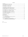
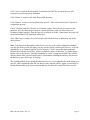
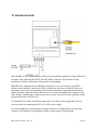
2. Connecting the BB27030 for the First Time (a) Connect power. Apply +12 to +24VDC or 24VAC to the terminal marked “POWER”, and
common or ground the the terminal marked “GND”.
(b) Connect a CAT5 cable between the RJ-45 jack on the top and your network switch or hub.
You cannot connect directly to your PC unless you use a “crossover” cable.
(c) Apply power. A blue LED inside the case should light indicating power is present. If the
yellow LED on the RJ45 jack is not on, check your Ethernet cable connections. Both green and
yellow LEDs on the RJ45 jack will be on solid for a time during boot-up. The entire bootup
process will take 1-2 minutes, during which time you will not be able to connect with a browser.
(d) The default IP address as shipped is 10.0.0.101. If your PC is not already on the 10.0.0.0
domain, you will need to add a route on your PC. Do this by opening a command prompt. First
type “ipconfig” and note the IP address listed. This is your PC’s IP address. Now type the
command
route add 10.0.0.0 mask 255.255.255.0 1.2.3.4
but substitute your PC’s IP address for 1.2.3.4.
This generally works, but if this fails, you will need to temporarily change your computer’s IP
address to a fixed address that starts with 10.0.0. and ends with anything but 101.
BB2-7030 User Guide – Rev. 1.0
Page 3
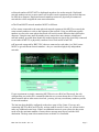
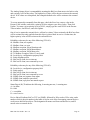
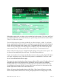
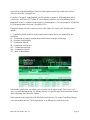
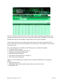
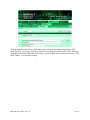
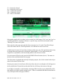
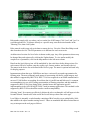
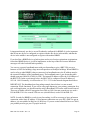
(e) Open your browser, and enter “http://10.0.0.101/” in the address window. You should see a
page with the “Babel Buster BB2-7030” header shown above. From this point, you will find help
on each page in the web site contained within the product.
(f) When you click on any of the page tabs such as System Setup, you will be asked for a user
name and password. The default login is user name “system” with password “admin”. You can
also log in as “root” using password “buster”. You should log in as “root” if you will be
changing the IP address.
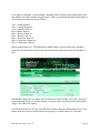
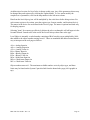
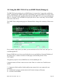
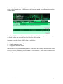
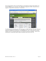
(g) To can change the IP address of the BB2-7030, go to the Local Host page under System ::
Setup. The following page should appear. Change the IP address, and subnet mask and gateway
if applicable. Click Change IP to save the changes. The process of programming this into Flash
takes around half a minute. The new IP address only takes effect following the next system
restart or power cycle.
BB2-7030 User Guide – Rev. 1.0
Page 4
(h) Most changes are stored in an XML configuration file in the device’s Flash file system. Only
a few are stored differently, and the IP address is one of those. Normally, clicking Update on any
configuration page only stores that configuration information to a temporary RAM copy of the
configuration file. To make your changes other than IP address permanent, you must click Save
on the Config File page (System :: Setup :: Config File).
BB2-7030 User Guide – Rev. 1.0
Page 5
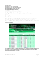
3. Minimum BB27030 Gateway/Router Setup The BB2-7030 requires only minimal configuration to be useful in its simplest form. First, you
must assign a device instance to the BB2-7030, and you do this via the BACnet IP Port page.
You may leave all other settings at their default. You could leave the device instance at its
default as well. The only real requirement is that you do not duplicate device instances.
The hardware will effectively prevent you from duplicating the MAC address on the IP side, but
you do need to select a MAC address for the MS/TP side of the router. Enter that MAC address
at the bottom of this page. The MAC addresses must not be duplicated on the network. Enter
your MS/TP baud rate and Max Master setting as well.
The second page that contains a minimum requirement is the Network Info page, under the
BACnet Router tab. The network info strings are just that, information only, and are optional.
The network numbers, however, are mandatory.
BB2-7030 User Guide – Rev. 1.0
Page 6
● Network numbers MUST NOT be duplicated anywhere else on the network. Duplicated
network numbers on two or more routers will result in erratic operation of the network that can
be difficult to diagnose. Duplicated network numbers means two physically disconnected
networks have been assigned the same network number.
● The IP and MS/TP network numbers MUST be different.
● Two routers connected to the same physical network segment or link MUST use exactly the
same network numbers to refer to that segment of the network. Using two different network
numbers to refer to the same physical network will result in erratic behavior that is difficult to
diagnose. Using the same network number in two routers does not constitute a duplicated
network number, provided those identically numbered ports are physically electrically connected
to each other if MS/TP, or physically connected via a local switch or hub if IP.
● IP networks connected by BB2-7030’s that are connected to each other via a WAN router
MUST be given different network numbers – they are considered physically independent
networks.
If your requirement is simply connecting MS/TP devices to a BACnet IP network, the only
configuration you need to do is contained within the two screens shown above. If there are no
other networks and no other routers involved, you may pick any two arbitrary numbers you like
for network numbers.
The last item that should be configured on the above page is Hop Count. If you are only
connecting MS/TP to BACnet IP locally, set that count to at most 2 since you will not need to
make any additional router hops. If there are additional routers in your system, the hop count
needs to be the maximum number of routers that a message must hop to reach the final
destination. The hop count is decremented once each time it is forwarded.
BB2-7030 User Guide – Rev. 1.0
Page 7
The primary use of hop count is to force packets on the network to be discarded faster,
particularly in the event of router misconfiguration that results in a continuous loop.
BB2-7030 User Guide – Rev. 1.0
Page 8
4. Using the BB27030 as a BACnet Router You do not actually need to do more than the minimum configuration mentioned above. If the
BACnet Router :: Remote Networks :: Configured page is left blank, the BB2-7030 will use
Who-Is-Router messages to “learn” the network. You have the option of pre-configuring the
router. This will save a little bit of time when the router first boots up, but will normally not
impact performance overall.
Enter the known remote network numbers and the ports via which they may be reached. The Info
strings are strictly informational and have no bearing on functionality.
The router's address is optional. If not given here, it will be searched for on the network using
Who-Is-Router. You may enter the remote router's address as an MS/TP MAC address, or an
IP address optionally with port number. If no port number is given, the BB2-7030's own local
port number will be used. IP should be given in the form of 192.168.1.199:47808 (for example)
or just 192.168.1.199.
It should be noted that even if you do enter the router's address here, it will be replaced in the
event an I-Am-Router message is received for the given network number but having a different
router address.
BB2-7030 User Guide – Rev. 1.0
Page 9
It should also be noted that if some external BACnet network management tool sends a router
table initialize message to this device, the entire page shown here will be replaced. After a delay
of a few minutes, the new contents of this page will be auto-saved to the XML configuration file
for subsequent reload. Thus, the router portion of this BB2-7030 may be remotely managed.
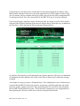
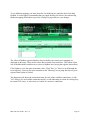
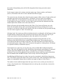
If you leave this page completely empty, all routers needed for routing of traffic will be located
using the Who-Is-Router broadcast to the network. Routers that are found this way, in addition to
any listed here, will be listed on the Discovered page illustrated below.
Use the Prev/Next buttons to scroll through the list of known networks. This list is a combination
of configured networks and those discovered via the Who-Is-Router and I-Am-Router message
exchange.
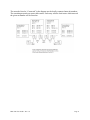
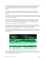
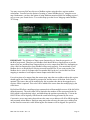
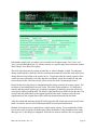
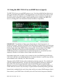
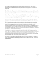
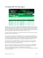
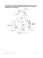
An example of a string of routers is illustrated below. This configuration is one of numerous test
scenarios that the BB2-7030 has been tested on. It represents a possible application, but would
represent a poorly configured network. There would normally be no reason to route alternately
between MS/TP and IP numerous times. The IP should be connected in a star configuration for
better performance. However, traffic does reach one end point from the other.
BB2-7030 User Guide – Rev. 1.0
Page 10
The networks listed as “Connected” in the diagram are the locally connected network numbers.
The remaining networks are router table entries. Each entry tells the local router which network
the given net number will be found on.
BB2-7030 User Guide – Rev. 1.0
Page 11
5. Using the BB27030 as a BACnet Server The BB2-7030 contains a set of BACnet objects whose only purpose is to store copies of data
obtained from other devices. This copy of data may then be queried by different devices, or
written to different devices by the BB2-7030 client functions.
The collection of objects includes Analog, Binary, and Multi-State types of objects, and includes
Input, (commandable) Output, and (writeable) Value types of each of those objects. The BB27030 also contains a Device object which is shared with router functions. All of the remaining
objects noted here are not used by routing functions.
The BB2-7030 is a BACnet router, and routes packets as defined for routing by the BACnet
protocol specification. The BB2-7030 is also a gateway and can perform certain gateway
functions regardless of whether being used for routing purposes. The gateway functions all rely
upon the input, output, and value objects that store copies of data from devices.
Data may be placed in the local objects by other devices writing to the BB2-7030, or by the
BB2-7030 querying other devices. When the BB2-7030 is configured to query other devices,
these operations are defined by “read maps” and “write maps” associated with the respective
client function (e.g. BACnet client, Modbus TCP client, SNMP client).
The following pages illustrate the Analog Input object page and the Analog Output object page.
The remaining object pages found in the BB2-7030 are virtually identical, and are not replicated
here.
BB2-7030 User Guide – Rev. 1.0
Page 12
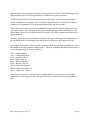
The source of data for an Analog Input object will be reading an object in another BACnet
device, or receiving of data from a Modbus (or SNMP) device. The device link will point to a
BACnet client read map or a Modbus (or SNMP) client read map.
Out of Service means any polling of the slave device will stop. While out of service, the present
value may be written by the BACnet client. Data may be forced via this web page at any time,
but will be overwritten by the next poll unless the object is out of service.
Reliability codes may be any of the following (7030-01):
64: Modbus client, no response
65: Modbus client, crc error
66: Modbus exception, illegal function code
67: Modbus exception, illegal data address
68: Modbus exception, illegal data value
69-79: Modbus exception, code+65, rarely used
80: Local device, configuration property fault
81: Faulty Modbus packet
82: BACnet IP client, device timeout
83: BACnet IP client, error returned by server
Reliability codes may be any of the following (7030-02):
80: Local device, configuration property fault
BB2-7030 User Guide – Rev. 1.0
Page 13
81: Faulty packet
82: BACnet IP client, device timeout
83: BACnet IP client, error returned by server
84: SNMP client, no response from agent
85: SNMP client, unable to parse data
86: SNMP client, reply does not match request
Status flags A,B,C,D indicate the following, 0 meaning not true, 1 meaning true:
A = in alarm
B = fault
C = overridden
D = out of service
Device link will indicate BAC or TCP, followed by R for read or W for write, and a number
which is the rule number in the table of read or write rules for mapping external devices or
objects to this BACnet object. The designation R means read from external device, and W means
write to external device.
The destination of data for an Analog Output object will be writing to another BACnet device, or
to a Modbus device. The external device will be updated upon change of source data and/or
periodically as defined by the Write Map.
BB2-7030 User Guide – Rev. 1.0
Page 14
The Analog Output object is commandable, meaning the BACnet client must write both a value
and a priority level for that value. The highest level value will be the one written to the external
device. If all values are relinquished, the relinquish default value will be written to the external
device.
To set an output object manually from this page, check the Force box, enter a value in the
Present Value window, and select a priority level to assign to your forced value. Then click
Update. To return a given priority level to NULL, simply type the word NULL in the Present
Value window, check Force, and click Update.
Out of service means the external device will not be written. Values written by the BACnet client
will be retained, but only applied when this object is placed back in service. At that time, the
highest priority value will be written to the external device.
Reliability codes may be any of the following (7030-01):
64: Modbus client, no response
65: Modbus client, crc error
66: Modbus exception, illegal function code
67: Modbus exception, illegal data address
68: Modbus exception, illegal data value
69-79: Modbus exception, code+65, rarely used
80: Local device, configuration property fault
81: Faulty Modbus packet
82: BACnet IP client, device timeout
83: BACnet IP client, error returned by server
Reliability codes may be any of the following (7030-02):
80: Local device, configuration property fault
81: Faulty packet
82: BACnet IP client, device timeout
83: BACnet IP client, error returned by server
84: SNMP client, no response from agent
85: SNMP client, unable to parse data
86: SNMP client, reply does not match request
Status flags A,B,C,D indicate the following, 0 meaning not true, 1 meaning true:
A = in alarm
B = fault
C = overridden
D = out of service
Device link will indicate BAC or TCP (or SNMP), followed by R for read or W for write, and a
number which is the rule number in the table of read or write rules for mapping external devices
or objects to this BACnet object. The designation R means read from external device, and W
means write to external device.
BB2-7030 User Guide – Rev. 1.0
Page 15
6. Using the BB27030 as a BACnet Client The BACnet client is used to query other BACnet devices, obtain their Present Value data, and
store a copy of that data in the BB2-7030’s own local objects. From there, the data may be
accessed by Modbus TCP or SNMP devices, or other BACnet devices when application specific
reasons make this approach more preferred than direct routing.
Setting up the BACnet client consists of identifying one or more BACnet devices, then listing the
objects that should be queried (whether read or written). The client configuration pages are
illustrated below.
Device number simply shows you where you are on the device list. Click "next" and "prev" to
scroll through the list.
Remote BACnet devices to be accessed by this device are specified here. Enter the
Device Instance of the remote device, a name to reference in other pages, a poll rate, default
reply timeout, and default write priority. Enter static address if applicable. Then click "update".
The gateway broadcasts a "who-is" looking for this device when a read or write map wants to use
this device. When (if) it responds, its IP address or MS/TP mac address is listed here simply as a
diagnostic. Timeouts resulting from inability to reach this device are tabulated on this page as
well, and may be cleared by clicking the Clear button. To cause the who-is process to be
repeated, click Clear Cache.
BACnet IP or MS/TP slave devices that to not support Who-Is/I-Am can still be supported here.
When this is the case, enter the slave device's Mac address in the Static Mac window and check
BB2-7030 User Guide – Rev. 1.0
Page 16
the 'No Who-Is' box. If located on a remote network via a router, enter the network number as
DNet. This static entry effectively replies to the implied Who-Is.
To use a fixed static address, enter a single number for MS/TP MAC address. or an IP address
optionally including port number. An example of IP address with port number would be
192.168.1.99:47808. The 47808 is the port number, and is separated from the IP address by a
colon. Note that 47808 is the default 0xBAC0 port number. If no port number is given, the port
configured on the BACnet IP Port page will be used (the BB2-7030's own port).
Map number simply tells you where you're at on the list of register maps. Click "next" and
"prev" to scroll through the list. To advance directly to a specific map, enter the desired number
in the "Showing" box, then click Update.
Maps entered on this page only read data from remote devices. Go to the Client Write Map to
write data to those devices. The full parameter set is different for read versus write.
An abbreviated version of a list of maps is shown on this page. Any of the parameters shown
may be changed here and registered by clicking the Update button. To view and/or modify the
complete set of parameters, click on the map number in the left most column.
For each remote object to be read, enter the object instance and type, and location (device). The
names in the device list are defined in the Devices page.
When the remote object is read, data may be manipulated before being written to the local object.
The value will be multiplied by the scale factor. The final result is written to the local object
number given. The name is optional and used only for display purposes.
Selecting "none" for remote type effectively deletes the map even though it will still appear in
the list until deleted. Unused maps at the end of the list will always show none as the type.
BB2-7030 User Guide – Rev. 1.0
Page 17
Local Object is internally a coded number consisting of BACnet object type multiplied by 1000,
then added to the object number starting from #1. These are translated into abbreviations that are
easy to interpret on the web page as follows:
AI n = Analog Input #n
AO n = Analog Output #n
AV n = Analog Value #n
BI n = Binary Input #n
BO n = Binary Output #n
BV n = Binary Value #n
MI n = Multi-state Input #n
MO n = Multi-state Output #n
MV n = Multi-state Value #n
Object numbers start at #1. The maximum available number varies by object type, and these
limits may be found on the System Capacities link from the home/index page (click graphic at
top).
Rule number simply tells you where you're at on the list of object maps. Click "next" and "prev"
to scroll through the list. To advance directly to a specific map, enter the desired number in the
"Map #" box, then click Update.
For each remote object to be read, enter the object instance and type, and location (device). The
names in the device list are defined in the Devices page. Use index value of 0 if no index.
BB2-7030 User Guide – Rev. 1.0
Page 18
When the remote object is read, data may be manipulated before being written to the local object.
The value will be multiplied by the scale factor, then the offset is added. The final result is
written to the local object number given. The name is optional and used only for display
purposes.
The periodic poll time determines how often the remote object will be read. This number, if
nonzero, will override the default poll time given in the Devices page for the remote device
being read.
The default value will be stored into the local object after the given number of read failures if the
fail count is non-zero. Setting the count to zero will disable the default, and the object will retain
the most recent value obtained.
Delete will remove the rule number shown in the "Map #" box. Insert will insert a new map
before the map number shown, and is used for placing maps between existing maps. It is not
necessary to use Insert to add maps to the bottom of the list or to define any map presently
having zero for a source object or "none" for remote type.
Selecting "none" for remote type effectively deletes the map even though it will still appear in
the list until deleted. Unused maps at the end of the list will always show none as the type. If you
wish to prevent these from being displayed, reduce the number of maps enabled.
The number of maps enabled simply limits the scope of map review so that you do not have to
review a lot of unused maps. If the displayed maps are used up and you need more, increase the
enabled number.
Map number simply tells you where you're at on the list of register maps. Click "next" and
"prev" to scroll through the list. To advance directly to a specific map, enter the desired number
in the "Showing" box, then click Update.
BB2-7030 User Guide – Rev. 1.0
Page 19
Maps entered on this page only write data to remote devices. Go to the Client Read Map to read
data from those devices. The full parameter set is different for read versus write.
An abbreviated version of a list of maps is shown on this page. Any of the parameters shown
may be changed here and registered by clicking the Update button. To view and/or modify the
complete set of parameters, click on the map number in the left most column.
Data from the local object given will be multiplied by the scale factor before being written. For
each remote object to be written, enter the object instance and type, and location (device). The
names in the device list are defined in the Devices page. The name is optional and used only for
display purposes.
Selecting "none" for remote type effectively deletes the map even though it will still appear in
the list until deleted. Unused maps at the end of the list will always show none as the type.
Local Object is internally a coded number consisting of BACnet object type multiplied by 1000,
then added to the object number starting from #1. These are translated into abbreviations that are
easy to interpret on the web page as follows:
AI n = Analog Input #n
AO n = Analog Output #n
AV n = Analog Value #n
BI n = Binary Input #n
BO n = Binary Output #n
BV n = Binary Value #n
MI n = Multi-state Input #n
MO n = Multi-state Output #n
MV n = Multi-state Value #n
Object numbers start at #1. The maximum available number varies by object type, and these
limits may be found on the System Capacities link from the home/index page (click graphic at
top).
BB2-7030 User Guide – Rev. 1.0
Page 20
Rule number simply tells you where you're at on the list of object maps. Click "next" and "prev"
to scroll through the list. To advance directly to a specific map, enter the desired number in the
"Map #" box, then click Update.
The local object data may be written periodically, or when it changes, or both. To send upon
change (send on delta), check the first box and enter the amount by which the local object must
change before being written to the remote device. To guarantee that the remote object will be
written at least occasionally even if the data does not change, check the second box and enter
some amount of time. This time period will be referred to as the "maximum quiet time".
Data from the local object may be manipulated before being written to the remote register. The
local data is first multiplied by the scale factor. The offset is then added to it.
For the remote object to be written, enter the object instance and type, index if applicable (leave
at 0 if not), and priority to use of the object being written is commandable. The names in the
device list are defined in the Devices page.
The repeat time may determine how often the remote object will be written. If send on delta and
maximum quiet time are not checked above, clicking the "at least" button will establish a
periodic update time. If send on delta is used and you wish to limit the network traffic in the
event changes are frequent, click the "no more than" button and enter the minumum time that
should elapse before another write to the remote device.
Delete will remove the rule number shown in the "Map #" box. Insert will insert a new map
before the map number shown, and is used for placing maps between existing maps. It is not
BB2-7030 User Guide – Rev. 1.0
Page 21
necessary to use Insert to add maps to the bottom of the list or to define any map presently
having zero for a source object or "none" for remote type.
Selecting "none" for remote type effectively deletes the map even though it will still appear in
the list until deleted. Unused maps at the end of the list will always show none as the type. If you
wish to prevent these from being displayed, reduce the number of maps enabled.
The number of maps enabled simply limits the scope of map review so that you do not have to
review a lot of unused maps. If the displayed maps are used up and you need more, increase the
enabled number.
Errors for BACnet IP client read maps are shown on this page. Only those maps with errors to
report are listed. Refer to the code and class lists below for interpretation.
Proprietary class 82, code 0, is generated locally indicating a timeout, no response received
from remote server. All other codes listed below are returned by the remote server.
0 = ERROR_CLASS_DEVICE
1 = ERROR_CLASS_OBJECT
2 = ERROR_CLASS_PROPERTY
3 = ERROR_CLASS_RESOURCES
4 = ERROR_CLASS_SECURITY
5 = ERROR_CLASS_SERVICES
/* valid for all classes */
0 = ERROR_CODE_OTHER
/* Error Class - Device */
2 = ERROR_CODE_CONFIGURATION_IN_PROGRESS
3 = ERROR_CODE_DEVICE_BUSY
BB2-7030 User Guide – Rev. 1.0
Page 22
25 = ERROR_CODE_OPERATIONAL_PROBLEM
/* Error Class - Object */
4 = ERROR_CODE_DYNAMIC_CREATION_NOT_SUPPORTED
17 = ERROR_CODE_NO_OBJECTS_OF_SPECIFIED_TYPE
23 = ERROR_CODE_OBJECT_DELETION_NOT_PERMITTED
24 = ERROR_CODE_OBJECT_IDENTIFIER_ALREADY_EXISTS
27 = ERROR_CODE_READ_ACCESS_DENIED
31 = ERROR_CODE_UNKNOWN_OBJECT
36 = ERROR_CODE_UNSUPPORTED_OBJECT_TYPE
/* Error Class - Property */
8 = ERROR_CODE_INCONSISTENT_SELECTION_CRITERION
9 = ERROR_CODE_INVALID_DATA_TYPE
32 = ERROR_CODE_UNKNOWN_PROPERTY
37 = ERROR_CODE_VALUE_OUT_OF_RANGE
40 = ERROR_CODE_WRITE_ACCESS_DENIED
41 = ERROR_CODE_CHARACTER_SET_NOT_SUPPORTED
42 = ERROR_CODE_INVALID_ARRAY_INDEX
44 = ERROR_CODE_NOT_COV_PROPERTY
45 = ERROR_CODE_OPTIONAL_FUNCTIONALITY_NOT_SUPPORTED
47 = ERROR_CODE_DATATYPE_NOT_SUPPORTED
50 = ERROR_CODE_PROPERTY_IS_NOT_AN_ARRAY
/* Error Class - Resources */
18 = ERROR_CODE_NO_SPACE_FOR_OBJECT
19 = ERROR_CODE_NO_SPACE_TO_ADD_LIST_ELEMENT
20 = ERROR_CODE_NO_SPACE_TO_WRITE_PROPERTY
/* Error Class - Security */
1 = ERROR_CODE_AUTHENTICATION_FAILED
6 = ERROR_CODE_INCOMPATIBLE_SECURITY_LEVELS
12 = ERROR_CODE_INVALID_OPERATOR_NAME
15 = ERROR_CODE_KEY_GENERATION_ERROR
26 = ERROR_CODE_PASSWORD_FAILURE
28 = ERROR_CODE_SECURITY_NOT_SUPPORTED
30 = ERROR_CODE_TIMEOUT
/* Error Class - Services */
5 = ERROR_CODE_FILE_ACCESS_DENIED
7 = ERROR_CODE_INCONSISTENT_PARAMETERS
10 = ERROR_CODE_INVALID_FILE_ACCESS_METHOD
11 = ERROR_CODE_ERROR_CODE_INVALID_FILE_START_POSITION
13 = ERROR_CODE_INVALID_PARAMETER_DATA_TYPE
14 = ERROR_CODE_INVALID_TIME_STAMP
16 = ERROR_CODE_MISSING_REQUIRED_PARAMETER
22 = ERROR_CODE_PROPERTY_IS_NOT_A_LIST
BB2-7030 User Guide – Rev. 1.0
Page 23
29 = ERROR_CODE_SERVICE_REQUEST_DENIED
43 = ERROR_CODE_COV_SUBSCRIPTION_FAILED
46 = ERROR_CODE_INVALID_CONFIGURATION_DATA
48 = ERROR_CODE_DUPLICATE_NAME
49 = ERROR_CODE_DUPLICATE_OBJECT_ID
BB2-7030 User Guide – Rev. 1.0
Page 24
7. Using the BB27030 as an MS/TP to BACnet IP gateway The difference between router and gateway for connecting MS/TP to BACnet IP is this: When
using the router, you address device instances other than the router itself. When using the
gateway, you address the gateway itself (the BB2-7030), reading and writing the objects found in
the gateway. There are several options for how the data got there. The point is that as a gateway,
you address the BB2-7030’s device instance.
To connect MS/TP to BACnet IP, or vice versa, you would start by setting up the BACnet client
to read/write objects in other devices. It is possible that the BB2-7030 acts as a data transfer
engine reading from one device and writing to another. It is also possible that the BB2-7030 acts
as a form of proxy server, reading data from one or more devices, storing that data, and waiting
for that data to be read by yet other devices. (This definition of proxy is not what is meant on the
Slave Proxy page.)
The BACnet client, or master, in the case of a gateway would treat the BB2-7030 as a single
device having some number of objects containing data. The main reason one would use the BB27030 as a gateway for BACnet to BACnet data transfer is to permit some sort of data filtering or
manipulation or alternate form of representation as the data is passed through.
BB2-7030 User Guide – Rev. 1.0
Page 25
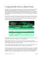
8. Configuring the BB2703001 as a Modbus TCP Server The term “server” is often used to describe the Modbus TCP version of a Modbus slave. A server
will provide data when a client asks for it. The concept of master/slave is less significant in
Modbus TCP because any TCP device can be both master and slave at the same time, and there
can be multiple “masters” on the network. That is in contrast with Modbus RTU where there can
be only one master and multiple slaves, and each device must be one or the other.
The Modbus TCP server is simply a collection of registers that may contain data. The source of
that data in the case of Babel Buster BB2-7030 can be any of several possible sources. It may be
read from another Modbus device. Another Modbus device could have put it there by writing to
the BB2-7030. The BACnet client could have read the data from another BACnet device.
Another BACnet device could have put it there by writing to the BB2-7030.
The collection of Modbus registers in the BB2-7030 are actually a collection of BACnet objects
that happen to have Modbus addresses as aliases.
Modbus register numbers for accessing data objects in the BB2-7030 are calculated. The register
number for binary and multi-state objects is R=T*1000+I where T is the BACnet Object Type,
and I is the instance (R is the resulting register number). The register number for analog objects,
because they must be read as a register pair, is R=T*1000+I*2-1 (R is the first register number in
the pair). Register numbers start at 1. To create a raw address, subtract 1 from the register
number.
Analog objects should be read as input registers or holding registers, and can only be written as
holding registers. Binary and multi-state objects can be read as any register type (coil, discrete,
input register, holding register), and can be written as coil or holding register.
Analog objects are always floating point data read as a register pair with most significant register
first unless the Swap box is checked on the Modbus page in the configuration tool. Attempting to
read or write an Analog object as a single register will produce an error.
Object types that may be used in Modbus register number calculation are:
0 – Analog Input
1 – Analog Output
2 – Analog Value
3 – Binary Input
4 – Binary Output
5 – Binary Value
13 – Multistate Input
14 – Multistate Output
19 – Multistate Value
BB2-7030 User Guide – Rev. 1.0
Page 26
You may access any BACnet object as a Modbus register using the above register number
calculations. You also have the option of creating a “virtual Modbus device” using the server
map. Furthermore, you have the option of using Modicon notation (40001 for holding register 1,
etc) to create your virtual device. You set this map up on the Server Map page under Modbus
TCP Setup.
IMPORTANT: The definition of Input versus Output object is from the perspective of
the BACnet network. Therefore your Modbus client should Write to Input objects to provide
input to BACnet, and Read from Output objects to receive output from BACnet. Attempting to
write a BACnet Output object from Modbus will not work properly. You must think of your
Modbus device as the physical I/O being accessed from BACnet. If you want to make your
Modbus device write to an Output object on another BACnet device, use the BACnet client
mapping to translate a local Input to remote Output on the BACnet side.
For each register to be mapped into the custom map, enter the server address where this register
should appear, the format it should be presented in, and the source of the data. Scale factor is
optional. The source data will be multiplied by this to produce the data in the mapped server
register. Offset is optional. This value will be added to the source data after multiplying by the
scale factor.
Bit field and fill allow compiling register contents derived from multiple sources if the bit field is
defined (nonzero). The source data will be limited to the number of bits represented in the bit
field (which is a hexadecimal value), and shifted into the position represented by '1' bits in the
field. Fill bits will be logically OR'ed into the result before being presented by the server.
Consecutive server map entries that reference the same server address will all be OR'ed together
and presented at that address. Duplicate map entries that reference the same server address but
are not listed in consecutive order following the first instance will be skipped. No special bit
BB2-7030 User Guide – Rev. 1.0
Page 27
field processing takes place if the bit field is set to zero. Bit fields apply to 16-bit integer or
unsigned integer server registers only.
The name is optional and is used for display purposes only.
Delete will remove the rule number shown in the "Showing" box. Insert will insert a new rule
before the rule number shown, and is used for placing rules between existing rules. It is not
necessary to use Insert to add rules to the bottom of the list or to define any rule presently having
"none" for register format.
Selecting "none" as the register format effectively deletes the rule even though it will still appear
in the list until deleted. Unused rules at the end of the list will always show "none" as the format.
If you wish to prevent these from being displayed, reduce the number of rules enabled.
Enter the number of Modbus registers that should be available in your customized register
mapping and check "User Map Enabled" to begin using a customized map. Check "Map is
Exclusive" if access to registers outside of this map should be prohibited. If exclusive is not
selected, all local registers not overlapped by the custom map will also be accessible to the
remote client.
By default, double registers in Control Solutions products are "big endian" meaning the most
significant bytes are in the first register and least significant bytes are in the second register. If
remote clients accessing this server at this IP address expect "little endian", check the swap box.
Modbus protocol by definition is "big endian" within each register, but the "endian" order of the
registers for 32-bit values is less standardized.
Normally an attempt to read an undefined register will return an exception (error) code. To
enable reading of large data packets without nuisance errors, you have the option of zero filling
null registers. This means that reading an undefined register in between valid defined registers
will simply return zero data rather than an error.
Check "Use Modicon mapping" to map 0X, 1X, 3X and 4X registers anywhere in i.CanDoIt
register space. When you use Modicon mapping, the Mapped Register number should be in the
following ranges:
Mapped Register #
Read (Write) as
Function codes expected
0-9999
Coil
1, 5, 15
10001-19999
Discrete Input
2
30001-39999
Input Register
4
40001-49999
Holding Register
3, 6, 16
Any of the Modicon register types may be mapped to any local register, except that coils and
discrete inputs cannot map to floating point registers. When a local register is read as coil or
discrete input, any nonzero value in the local register will return a set bit, and zero in the local
register will return a clear bit. Local registers written as coils will be set to 0 or 1.
BB2-7030 User Guide – Rev. 1.0
Page 28
To use Modicon mapping, you must check the Use Modicon box, and also check User Map
Enabled. It is also highly recommended that you check the Map is Exclusive box when using
Modicon mapping. Remember to go to the Config File page and save your changes.
The values of Modbus registers that have been created by the virtual server mapping are
displayed on this page. These are the values that a remote client would see. (The remote client
acts as Modbus master, and this server acts as a Modbus slave having the registers shown here.)
Click Update to view the most recent data values. Click "Prev" or "Next" to scroll through the
list of registers. You may also enter a number in the "Showing" box to jump directly to a given
register when Update is clicked.
The diagnostic info shows the connection status for each of the available connections. A code
"a/b" where a=0 is an available connection and b is a code indicating its reason for closing (may
be normal TCP close). A code where a>0 and b=0 is an active connection.
BB2-7030 User Guide – Rev. 1.0
Page 29
9. Configuring the BB2703001 as a Modbus TCP Client The BB2-7030-01 can be a Modbus client or server. As a client (master) you can read Modbus
data from, or write Modbus data to, other Modbus servers (slaves). The BB2-7030 will
periodically poll the other Modbus devices according to register maps you set up. The Modbus
server (slave) devices that you will read/write are defined on the Devices page. To read from a
remote Modbus device, configure a Read Map. To write to a remote Modbus device, configure
Write Map.
Data read from a remote device is stored in a local data object when received. Data written to a
remote device is taken from a local data object when sent. The local data objects are the same
collection of objects that are accessible to other clients via the server map, and accessible to
other BACnet devices via MS/TP or BACnet IP.
The Modbus Devices page is illustrated above. Device number simply shows you where you are
on the device list. Click "next" and "prev" to scroll through the list.
Remote Modbus/TCP devices to be accessed by this device are specified here. Enter the
IP address of the remote device, a name to reference in other pages, a unit number, poll rate, and
check "swapped" if appropriate. Then click "update".
If your slave/server device only supports function codes 5 and 6 for writing, check the Use FC
5/6 box. The default function codes are 15 and 16, which are most widely used.
The term "swapped" only applies to double or float formats. Modbus registers are, by definition,
16 bits of data per register. Access to 32-bit data, either 32-bit integer ("double"), or IEEE 754
floating point ("float"), is supported by the use of two consecutive registers. Modbus protocol is
inherently "big endian", therefore, Modbus by the Module defaults to having the high order
BB2-7030 User Guide – Rev. 1.0
Page 30
register first for double and float. If the low order register comes first on the device being
accessed, check the "swapped" box.
If you have "swapped" turned around, you will quickly recognize it. If floating point data is
reversed, a 1.0 becomes 2.2779508e-41, which simply rounds to zero. The pattern is not as
predictable as the 1.0 example would suggest. A floating point 1.1 becomes negative 107609184.
If 32-bit integer data is reversed, 1 becomes 65536.
Connection status will show a non-zero error code if there is a socket error. Possible errors
include:
5 = Connection failed, unable to bind (usually means remote device not connected or not
reachable)
81 = Connection in progress (means unsuccessful connect attempt, still trying)
95 = Network is unreachable
97 = Connection aborted
98 = Connection reset by peer
103 = Connection timed out
104 = Connection refused
107 = Host is unreachable
Rule number simply tells you where you're at on the list of register maps. Click "next" and
"prev" to scroll through the list. To advance directly to a specific map, enter the desired number
in the "Showing" box, then click Update.
Rules entered on this page only read data from remote devices. Go to the Client Write Map to
write data to those devices. The full parameter set is different for read versus write.
BB2-7030 User Guide – Rev. 1.0
Page 31
An abbreviated version of a list of rules is shown on this page. Any of the parameters shown may
be changed here and registered by clicking the Update button. To view and/or modify the
complete set of parameters, click on the map number in the left most column.
For each remote register to be read, enter the register type, format, number, and location
(device). The names in the device list are defined in the Devices page.
When the remote register is read, the data will be multiplied by the scale factor and written to the
local object number given. The name is optional and used only for display purposes.
Selecting "none" for remote type effectively deletes the rule even though it will still appear in the
list until deleted. Unused rules at the end of the list will always show none as the type.
Local Object is internally a coded number consisting of BACnet object type multiplied by 1000,
then added to the object number starting from #1. These are translated into abbreviations that are
easy to interpret on the web page as follows:
AI n = Analog Input #n
AO n = Analog Output #n
AV n = Analog Value #n
BI n = Binary Input #n
BO n = Binary Output #n
BV n = Binary Value #n
MI n = Multi-state Input #n
MO n = Multi-state Output #n
MV n = Multi-state Value #n
Object numbers start at #1. The maximum available number varies by object type, and these
limits may be found on the System Capacities link from the home/index page (click graphic at
top).
BB2-7030 User Guide – Rev. 1.0
Page 32
Rule number simply tells you where you're at on the list of register maps. Click "next" and
"prev" to scroll through the list. To advance directly to a specific map, enter the desired number
in the "Map #" box, then click Update.
For each remote register to be read, enter the register type, format, number, and location
(device). The names in the device list are defined in the Devices page.
When the remote register is read, data may be manipulated before being written to the local
object. If a bit mask is entered (in hexadecimal), and the remote register type is signed or
unsigned (16-bit data), the mask will be bit-wise logical AND-ed with the data, and the retained
bits will be right justified in the result. The result will then be multiplied by the scale factor. The
offset is then added and this final result is written to the local object number given. The name is
optional and used only for display purposes.
The periodic poll time determines how often the remote register will be read. This number, if
nonzero, will override the default poll time given in the Devices page for the remote device
being read.
The default value will be stored into the local object after the given number of read failures if the
fail count is non-zero. Setting the count to zero will disable the default, and the object will retain
the most recent value obtained.
Delete will remove the rule number shown in the "Map #" box. Insert will insert a new rule
before the rule number shown, and is used for placing rules between existing rules. It is not
necessary to use Insert to add rules to the bottom of the list or to define any rule presently having
zero for a source object or "none" for remote type.
BB2-7030 User Guide – Rev. 1.0
Page 33
Selecting "none" for remote type effectively deletes the rule even though it will still appear in the
list until deleted. Unused rules at the end of the list will always show none as the type. If you
wish to prevent these from being displayed, reduce the number of rules enabled.
Initial COV increment and period will only apply if a BACnet client subscribes to COV
notification from the BACnet object assigned to this Modbus map. These properties may be
overwritten by the BACnet client(s) at any time. The values shown here are initial values, not
necessarily the current values. (Note: COV increment only applies to Analog objects, all changes
are reported for Binary or Multistate objects.)
Units default to no_units, but you may select any of the available BACnetEngineeringUnits
values. This value will simply be read by the BACnet client when the units property is requested
from the object this Modbus register maps to. The units have no bearing on calculations
performed. You must select appropriate scale and offset values to make any required translation
between Modbus units and BACnet units. Units are only valid for Analog objects.
The number of rules enabled simply limits the scope of rule review so that you do not have to
review a lot of unused rules. If the displayed rules are used up and you need more, increase the
enabled number.
Rule number simply tells you where you're at on the list of register maps. Click "next" and
"prev" to scroll through the list. To advance directly to a specific map, enter the desired number
in the "Showing" box, then click Update.
Rules entered on this page only write data to remote devices. Go to the Client Read Map to read
data from those devices. The full parameter set is different for read versus write.
BB2-7030 User Guide – Rev. 1.0
Page 34
An abbreviated version of a list of rules is shown on this page. Any of the parameters shown may
be changed here and registered by clicking the Update button. To view and/or modify the
complete set of parameters, click on the map number in the left most column.
Data from the local object given will be multiplied by the scale factor before being written. For
each remote register to be written, enter the register type, format, number, and location (device).
The names in the device list are defined in the Devices page. The name is optional and used only
for display purposes.
Selecting "none" for remote type effectively deletes the rule even though it will still appear in the
list until deleted. Unused rules at the end of the list will always show none as the type.
Local Object is internally a coded number consisting of BACnet object type multiplied by 1000,
then added to the object number starting from #1. These are translated into abbreviations that are
easy to interpret on the web page as follows:
AI n = Analog Input #n
AO n = Analog Output #n
AV n = Analog Value #n
BI n = Binary Input #n
BO n = Binary Output #n
BV n = Binary Value #n
MI n = Multi-state Input #n
MO n = Multi-state Output #n
MV n = Multi-state Value #n
Object numbers start at #1. The maximum available number varies by object type, and these
limits may be found on the System Capacities link from the home/index page (click graphic at
top).
BB2-7030 User Guide – Rev. 1.0
Page 35
Rule number simply tells you where you're at on the list of register maps. Click "next" and
"prev" to scroll through the list. To advance directly to a specific map, enter the desired number
in the "Map #" box, then click Update.
The local object data may be written periodically, or when it changes, or both. To send upon
change (send on delta), check the first box and enter the amount by which the local object must
change before being written to the remote device. To guarantee that the remote register will be
written at least occasionally even if the data does not change, check the second box and enter
some amount of time. This time period will be referred to as the "maximum quiet time".
Data from the local object may be manipulated before being written to the remote register. The
local data is first multiplied by the scale factor. The offset is then added to it. If a bit mask is
entered, and the remote register type is signed or unsigned (16-bit data), the mask will be bitwise logical AND-ed with the data. The mask is right justified, then AND-ed with the data. The
result is then left shifted back to the original position of the mask. In other words, the least
significant bits of the original data will be stuffed at the position marked by the mask.
After the scaling and masking, the bit fill will be logically OR-ed into the result, but only if the
mask was nonzero and was used. Both mask and fill are entered in hexadecimal.
Multiple local objects may be packed into a single remote register. To accomplish this, define
two or more rules in sequence with the same remote destination. If the destination is the same,
data types are 16-bit (integer or unsigned), bit masks are nonzero, and the rules are sequential,
BB2-7030 User Guide – Rev. 1.0
Page 36
the results of all qualifying rules will be OR-ed together before being sent to the remote
destination.
For the remote register to be written, enter the register type, format, number, and location
(device). The names in the device list are defined in the Devices page.
The repeat time may determine how often the remote register will be written. If send on delta and
maximum quiet time are not checked above, clicking the "at least" button will establish a
periodic update time. If send on delta is used and you wish to limit the network traffic in the
event changes are frequent, click the "no more than" button and enter the minumum time that
should elapse before another write to the remote device.
Delete will remove the rule number shown in the "Map #" box. Insert will insert a new rule
before the rule number shown, and is used for placing rules between existing rules. It is not
necessary to use Insert to add rules to the bottom of the list or to define any rule presently having
zero for a source register or "none" for remote type.
Selecting "none" for remote type effectively deletes the rule even though it will still appear in the
list until deleted. Unused rules at the end of the list will always show none as the type. If you
wish to prevent these from being displayed, reduce the number of rules enabled.
Initial COV increment and period will only apply if a BACnet client subscribes to COV
notification from the BACnet object assigned to this Modbus map. These properties may be
overwritten by the BACnet client(s) at any time. The values shown here are initial values, not
necessarily the current values. (Note: COV increment only applies to Analog objects, all changes
are reported for Binary or Multistate objects.)
Units default to no_units, but you may select any of the available BACnetEngineeringUnits
values. This value will simply be read by the BACnet client when the units property is requested
from the object this Modbus register maps to. The units have no bearing on calculations
performed. You must select appropriate scale and offset values to make any required translation
between Modbus units and BACnet units. Units are only valid for Analog objects.
Initial Relinquish Default may be set here, but may be overwritten by the BACnet client at any
time. This window reflects the initial value, not the current value. (Note: Relinquish Default only
applies to commandable Output objects, and does not apply to Input or Value objects.)
The number of rules enabled simply limits the scope of rule review so that you do not have to
review a lot of unused rules. If the displayed rules are used up and you need more, increase the
enabled number.
BB2-7030 User Guide – Rev. 1.0
Page 37
The first occurrence of read and write errors are shown along with the map number that was
being processed when the error occurred. Check the reset box and click update to clear it and
possibly show the next error if there are more than one active error conditions.
A total count of all errors is also shown. This total is the sum of errors for all maps for this
device. Check the reset box and click update to reset the counts. Click Update to view the most
recent data values.
Error code indications of A/B indicate the following errors with the first number:
1 = Transaction ID out of sync
2 = Exception code returned by remote device
3 = Function code mismatch (bad packet)
4 = Inusfficient data (bad packet)
5 = No response from remote device, timed out
6 = CRC error in received packet
When A is code 2 indicating an exception code was returned, B indicates the exception as
follows:
1 = Illegal function code
2 = Illegal data address (the requested register does not exist in the device)
3 = Illegal data value
BB2-7030 User Guide – Rev. 1.0
Page 38
10. Using the BB2703001 as a BACnet to Modbus TCP Gateway The possible reasons for using the BB2-7030 as a BACnet to Modbus TCP gateway are fairly
obvious: Either you want to access BACnet devices from Modbus TCP, or you want to access
Modbus TCP devices from BACnet. The BB2-7030 allows you to access Modbus TCP from
either MS/TP or BACnet IP, and vice versa.
Configuration begins with determining what the source of data is. If the source of data is BACnet
devices, then start by configuring the BACnet client. If the source of data is Modbus TCP
devices, then start by configuring the Modbus client.
The BB2-7030 can be a “slave” on either the BACnet or Modbus network. If the application
wants to view BACnet data as if it was a Modbus slave, configure the BACnet client and then
review the Modbus register map for accessing the data objects in the BB2-7030. If the
application wants to view Modbus TCP data as if it was a BACnet slave, configure the Modbus
client and then address the BB2-7030’s internal data objects from BACnet.
The BB2-7030 can be “slave” on both BACnet and Modbus sides at the same time. The BB27030 can also be “master” on both BACnet and Modbus sides at the same time. To be a slave on
both sides, no client functions need to be configured (no read/write maps entered). To be a
master on both sides, both the BACnet client and Modbus client need to be configured. When
both clients are configured and both sides are acting as master, you are now actively transferring
data from BACnet slaves to Modbus slaves or vice versa.
BB2-7030 User Guide – Rev. 1.0
Page 39
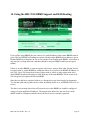
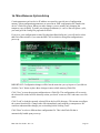
11. Using the BB2703002 as an SNMP Server (Agent) The BB2-7030-02 can act as an SNMP agent or server. You select which BACnet objects are to
show up in the MIB, and the MIB is created dynamically as you fill out the list of objects. Once
the MIB is created, any standard v1 or v2 SNMP manager can access the data. Integer data is
most universally recognized by SNMP. Floating point support is available in the BB2-7030;
however, floating point is not standardized and you should test compatibility.
IMPORTANT: The definition of Input versus Output object is from the perspective of
the BACnet network. Therefore your SNMP client should Write to Input objects to provide input
to BACnet, and Read from Output objects to receive output from BACnet. Attempting to write a
BACnet Output object from SNMP will not work properly. You must think of your SNMP
manager as the physical I/O being accessed from BACnet. If you want to make your
SNMP manager write to an Output object on another BACnet device, use the BACnet client
mapping to translate a local Input to remote Output on the BACnet side.
Rule number simply tells you where you're at on the list of the local SNMP Agent's OID maps.
Click "next" and "prev" to scroll through the list. To advance directly to a specific map, enter the
desired number in the "Showing" box, then click Update.
This page enables SNMP Get/Set to objects indicated on the above map list. The available local
OID's are assigned automatically. You may select which local BACnet objects are mapped to
these OID's. The only data type supported via the internal SNMP Agent is signed integer,
therefore you must use scaling to provide real data as integers. This is an inherent limitation of
SNMP which does not have any universally accepted method of transmitting floating point data.
Internal data is multiplied by the scale factor when read by your remote SNMP manager (client).
Data written by your SNMP client is divided by the scale factor before being stored internally.
BB2-7030 User Guide – Rev. 1.0
Page 40
For each local object to be accessed by the remote SNMP Client, enter the local object number
and scale factor. The local data and object name will be shown for reference. The data returned
to the remote SNMP client will be the indicated local value multiplied by the scale factor, then
truncated to integer. Enter an object number, then click Update to add the mapping to the list.
Objects are not immediately available when entered in the list above. When you have finished
making changes, click the Reload SNMP button to clear and reload the MIB. The MIB is also
automatically reloaded every time you restart this device.
Entering zero (none) for local object effectively deletes the rule even though it will still appear in
the list until deleted. Unused rules at the end of the list will always show none as the type.
Local Object is internally a coded number consisting of BACnet object type multiplied by 1000,
then added to the object number starting from #1. These are translated into abbreviations that are
easy to interpret on the web page as follows:
AI n = Analog Input #n
AO n = Analog Output #n
AV n = Analog Value #n
BI n = Binary Input #n
BO n = Binary Output #n
BV n = Binary Value #n
MI n = Multi-state Input #n
MO n = Multi-state Output #n
MV n = Multi-state Value #n
Object numbers start at #1. The maximum available number varies by object type, and these
limits may be found on the System Capacities link from the home/index page (click graphic at
top).
BB2-7030 User Guide – Rev. 1.0
Page 41
OID number simply tells you where you're at on the list of the local SNMP Agent's OID maps.
Click "next" and "prev" to scroll through the list. To advance directly to a specific map, enter the
desired number in the "Showing" box, then click Update. You cannot proceed to a trap rule for
an OID that has not been defined on the Local MIB page.
Select a comparison or test, and click the button for your choice of what the local register should
be compared to. Then enter either the fixed value for threshold.
Quaifications are optional, and enabled only when values are nonzero. How hysteresis is applied
depends on the comparison. For a test that becomes true if greater than, the test will not return to
false until the local register is less than the test value by a margin of at least this hysteresis value.
If a test becomes true if less than, it will not return to false until the local register is greater than
the test value by a margin of at least this hysteresis value.
On time and off time, if specified, determine how long the condition must be true (on time) or
false (off time) before the true or false response is actually taken. Times are given in
HH:MM:SS format (hours, minutes, seconds).
The repeat count is the number of times the same trap will be sent when triggered. This number
of traps will be sent at approximately 100 millisecond intervals. The repeat time is the delay
period between re-transmissions of the trap, or series of traps as determined by the repeat count.
Repeat time is in seconds. Example: If repeat count is set to 3, and repeat time is set to 60
seconds, then three trap messages will be sent in a burst and this burst will be repeated once
every minute.
BB2-7030 User Guide – Rev. 1.0
Page 42
Traps generated by this device will be sent to port 162 on each IP address listed above. The
name, location, and contact listed above may be retrieved by the remote SNMP client. The local
community is the name that must be used by the remote SNMP client to write to this device. The
name "public" is accepted for reading.
BB2-7030 User Guide – Rev. 1.0
Page 43
12. Using the BB2703002 as an SNMP Client (Manager) The BB2-7030 has the ability to be an SNMP client. In “master/slave” terms, this would be the
master. Configuring the SNMP client starts with defining one or more SNMP devices that will be
queried. Then, like the other possible client functions in the BB2-7030, you set up read and write
maps. A “read map” will use SNMP Get to query the device, and a “write map” will use SNMP
Set to write to the device.
The SNMP Client configuration pages are illustrated below along with a summary of how to use
them.
Device number simply shows you where you are on the device list. Click "next" and "prev" to
scroll through the list.
Remote SNMP devices to be accessed by this device are specified here. Enter the IP address of
the remote device, a name to reference in other pages, and a default poll rate. Then
click "update".
This gateway expects to access SNMP devices via the standard port 161.
Connection status will show a non-zero error code if there is a socket error. Possible errors
include:
5 = Connection failed, unable to bind (usually means remote device not connected or not
reachable)
81 = Connection in progress (means unsuccessful connect attempt, still trying)
95 = Network is unreachable
BB2-7030 User Guide – Rev. 1.0
Page 44
97 = Connection aborted
98 = Connection reset by peer
103 = Connection timed out
104 = Connection refused
107 = Host is unreachable
Rule number simply tells you where you're at on the list of OID maps. Click "next" and "prev" to
scroll through the list. To advance directly to a specific map, enter the desired number in the
"Showing" box, then click Update.
Rules entered on this page only read data from remote devices. Go to the Client Write Map to
write data to those devices. The full parameter set is different for read versus write.
An abbreviated version of a list of rules is shown on this page. Any of the parameters shown may
be changed here and registered by clicking the Update button. To view and/or modify the
complete set of parameters, click on the map number in the left most column.
For each remote OID to be read, enter the full SNMP OID and location (device). The names in
the device list are defined in the Devices page.
The object name is optional and used only for display purposes, but is also returned as the object
name to the remote BACnet client.
Entering zero (none) for local object effectively deletes the rule even though it will still appear in
the list until deleted. Unused rules at the end of the list will always show none as the type.
Local Object is internally a coded number consisting of BACnet object type multiplied by 1000,
then added to the object number starting from #1. These are translated into abbreviations that are
easy to interpret on the web page as follows:
BB2-7030 User Guide – Rev. 1.0
Page 45
AI n = Analog Input #n
AO n = Analog Output #n
AV n = Analog Value #n
BI n = Binary Input #n
BO n = Binary Output #n
BV n = Binary Value #n
MI n = Multi-state Input #n
MO n = Multi-state Output #n
MV n = Multi-state Value #n
Object numbers start at #1. The maximum available number varies by object type, and these
limits may be found on the System Capacities link from the home/index page (click graphic at
top).
Rule number simply tells you where you're at on the list of OID maps. Click "next" and "prev" to
scroll through the list. To advance directly to a specific map, enter the desired number in the
"Map #" box, then click Update.
For each remote OID to be read, enter the full OID and location (device). The names in the
device list are defined in the Devices page.
When the remote OID is read, data may be manipulated before being written to the local object.
The result will be multiplied by the scale factor if any non-zero scale factor is given. The offset
is then added and this final result is written to the local object number given. The name is
optional and used only for display purposes (but will also be returned as the object name to the
BACnet client).
BB2-7030 User Guide – Rev. 1.0
Page 46
The periodic poll time determines how often the remote OID will be read. This number, if
nonzero, will override the default poll time given in the Devices page for the remote device
being read.
The default value will be stored into the local object after the given number of read failures if the
fail count is non-zero. Setting the count to zero will disable the default, and the object will retain
the most recent value obtained.
Delete will remove the rule number shown in the "Map #" box. Insert will insert a new rule
before the rule number shown, and is used for placing rules between existing rules. It is not
necessary to use Insert to add rules to the bottom of the list or to define any rule presently having
zero for a source object or "none" for remote type.
Entering zero (for none) for local object effectively deletes the rule even though it will still
appear in the list until deleted. Unused rules at the end of the list will always show none as the
type. If you wish to prevent these from being displayed, reduce the number of rules enabled.
Initial COV increment and period will only apply if a BACnet client subscribes to COV
notification from the BACnet object assigned to this SNMP client map. These properties may be
overwritten by the BACnet client(s) at any time. The values shown here are initial values, not
necessarily the current values. (Note: COV increment only applies to Analog objects, all changes
are reported for Binary or Multistate objects.)
Units default to no_units, but you may select any of the available BACnetEngineeringUnits
values. This value will simply be read by the BACnet client when the units property is requested
from the object this OID maps to. The units have no bearing on calculations performed. You
must select appropriate scale and offset values to make any required translation between SNMP
units and BACnet units. Units are only valid for Analog objects.
The number of rules enabled simply limits the scope of rule review so that you do not have to
review a lot of unused rules. If the displayed rules are used up and you need more, increase the
enabled number.
BB2-7030 User Guide – Rev. 1.0
Page 47
Rule number simply tells you where you're at on the list of OID maps. Click "next" and "prev" to
scroll through the list. To advance directly to a specific map, enter the desired number in the
"Showing" box, then click Update.
Rules entered on this page only write data to remote devices. Go to the Client Read Map to read
data from those devices. The full parameter set is different for read versus write.
An abbreviated version of a list of rules is shown on this page. Any of the parameters shown may
be changed here and registered by clicking the Update button. To view and/or modify the
complete set of parameters, click on the map number in the left most column.
Data from the local object given will be multiplied by the scale factor before being written. For
each remote OID to be written, enter the register type, format, number, and location (device).
The names in the device list are defined in the Devices page. The name is optional and used only
for display purposes.
Important note about data type: SNMP does not have a universally accepted representation for
floating point. The most commonly used means of representing real data is scaled integers, and
this method is supported by BB2-7010. IEEE 754 is not recognized as an SNMP standard and is
not used. X.690 defines an encoding for real data, but it is inefficient and little used. A common
recommendation is to use ASCII string representation of floating point data, and this method is
supported by BB2-7010 (Octet String Num). Another known but application specific
implementation is the ASN OPAQUE FLOAT used in netsnmp applications. This method is also
supported by BB2-7010 but should be tested to confirm compatibility.
Selecting "none" for remote type effectively deletes the rule even though it will still appear in the
list until deleted. Unused rules at the end of the list will always show none as the type.
Local Object is internally a coded number consisting of BACnet object type multiplied by 1000,
then added to the object number starting from #1. These are translated into abbreviations that are
easy to interpret on the web page as follows:
BB2-7030 User Guide – Rev. 1.0
Page 48
AI n = Analog Input #n
AO n = Analog Output #n
AV n = Analog Value #n
BI n = Binary Input #n
BO n = Binary Output #n
BV n = Binary Value #n
MI n = Multi-state Input #n
MO n = Multi-state Output #n
MV n = Multi-state Value #n
Object numbers start at #1. The maximum available number varies by object type, and these
limits may be found on the System Capacities link from the home/index page (click graphic at
top).
Rule number simply tells you where you're at on the list of OID maps. Click "next" and "prev" to
scroll through the list. To advance directly to a specific map, enter the desired number in the
"Map #" box, then click Update.
The local object data may be written periodically, or when it changes, or both. To send upon
change (send on delta), check the first box and enter the amount by which the local object must
change before being written to the remote device. To guarantee that the remote OID will be
written at least occasionally even if the data does not change, check the second box and enter
some amount of time. This time period will be referred to as the "maximum quiet time".
BB2-7030 User Guide – Rev. 1.0
Page 49
Data from the local object may be manipulated before being written to the remote OID. The local
data is first multiplied by the scale factor. The offset is then added to it. The data is then sent to
the remote SNMP agent. Enter the full OID to be written, the SNMP ASN data type to be written
(select from list), and the location (device). The names in the device list are defined in the
Devices page.
Important note about data type: SNMP does not have a universally accepted representation for
floating point. The most commonly used means of representing real data is scaled integers, and
this method is supported by BB2-7010. IEEE 754 is not recognized as an SNMP standard and is
not used. X.690 defines an encoding for real data, but it is inefficient and little used. A common
recommendation is to use ASCII string representation of floating point data, and this method is
supported by BB2-7010 (Octet String Num). Another known but application specific
implementation is the ASN OPAQUE FLOAT used in netsnmp applications. This method is also
supported by BB2-7010 but should be tested to confirm compatibility.
The repeat time may determine how often the remote OID will be written. If send on delta and
maximum quiet time are not checked above, clicking the "at least" button will establish a
periodic update time. If send on delta is used and you wish to limit the network traffic in the
event changes are frequent, click the "no more than" button and enter the minumum time that
should elapse before another write to the remote device.
Delete will remove the rule number shown in the "Map #" box. Insert will insert a new rule
before the rule number shown, and is used for placing rules between existing rules. It is not
necessary to use Insert to add rules to the bottom of the list or to define any rule presently having
zero/none for a source object.
Selecting "none" for remote type effectively deletes the rule even though it will still appear in the
list until deleted. Unused rules at the end of the list will always show none as the type. If you
wish to prevent these from being displayed, reduce the number of rules enabled.
Initial COV increment and period will only apply if a BACnet client subscribes to COV
notification from the BACnet object assigned to this Modbus map. These properties may be
overwritten by the BACnet client(s) at any time. The values shown here are initial values, not
necessarily the current values. (Note: COV increment only applies to Analog objects, all changes
are reported for Binary or Multistate objects.)
Units default to no_units, but you may select any of the available BACnetEngineeringUnits
values. This value will simply be read by the BACnet client when the units property is requested
from the object this OID maps to. The units have no bearing on calculations performed. You
must select appropriate scale and offset values to make any required translation between SNMP
units and BACnet units. Units are only valid for Analog objects.
Initial Relinquish Default may be set here, but may be overwritten by the BACnet client at any
time. This window reflects the initial value, not the current value. (Note: Relinquish Default only
applies to commandable Output objects, and does not apply to Input or Value objects.)
BB2-7030 User Guide – Rev. 1.0
Page 50
The number of rules enabled simply limits the scope of rule review so that you do not have to
review a lot of unused rules. If the displayed rules are used up and you need more, increase the
enabled number.
Errors for SNMP client read maps are shown on this page. Only those maps with errors to report
are listed. Refer to the code and class lists below for interpretation.
Common error codes for the SNMP client are as follows:
9 = No response from remote Agent (server)
10 = Unable to interpret data
11 = Reply does not match request
Other error codes are possible but improbable. Codes in the 80-120 range indicate socket errors;
however, because SNMP uses UDP/IP, which is "connectionless", socket errors would indicate
something internal is seriously broken.
BB2-7030 User Guide – Rev. 1.0
Page 51
13. Using the BB2703002 as a BACnet to SNMP Gateway The possible reasons for using the BB2-7030 as a BACnet to SNMP gateway are fairly obvious:
Either you want to access BACnet devices from SNMP, or you want to access SNMP devices
from BACnet. The BB2-7030 allows you to access SNMP from either MS/TP or BACnet IP, and
vice versa.
Configuration begins with determining what the source of data is. If the source of data is BACnet
devices, then start by configuring the BACnet client. If the source of data is SNMP devices, then
start by configuring the SNMP client.
The BB2-7030 can be a “slave” on either the BACnet or SNMP network. If the application wants
to view BACnet data as if it was an SNMP “slave” (server or agent), configure the BACnet client
and also configure the SNMP MIB under the SNMP Agent tab. If the application wants to view
SNMP data as if it was a BACnet slave, configure the SNMP client and then address the BB27030’s internal data objects from BACnet.
The BB2-7030 can be “slave” on both BACnet and SNMP sides at the same time. The BB2-7030
can also be “master” on both BACnet and SNMP sides at the same time. To be a slave on both
sides, only the SNMP MIB needs to be set up under the SNMP Agent tab. To be a master on
both sides, both the BACnet client and SNMP client need to be configured. When both clients
are configured and both sides are acting as master, you are now actively transferring data from
BACnet slaves to SNMP slaves (servers/agents) or vice versa.
BB2-7030 User Guide – Rev. 1.0
Page 52
14. Using the BB27030 Proxy Support This page allows you to provide Who-Is support (dynamic address binding) for devices that do
not natively support that feature. The BB2-7030 will respond with an I-Am message on behalf of
the device(s) listed above when a Who-Is is received. Traffic subsequently received from the
above devices will be routed as applicable. Therefore the BB2-7030 can be a proxy for a BACnet
IP device responding to a Who-Is from an MS/TP device, and vice versa.
Select the local port to which the device is physically attached. Slave proxy support can only be
provided for locally connected devices.
For each device that this BB2-7030 should be a proxy for, enter the applicable information in
each column. The device instance, maximum APDU size, vendor ID, and segmentation support
are all reported in a BACnet I-Am message. The local physical address of the device should be
given so that the BB2-7030 knows where to route traffice for this device when received.
If you do not know the maximum APDU size for your device, a size of 1476 is common for
BACnet IP devices, and either 240 or 480 are common for MS/TP devices. If unknown, it is
safer to go with a size that is too small than too big.
The device's address is NOT optional. You may enter the device's address as an MS/TP MAC
address, or an IP address optionally with port number. If no port number is given, the BB27030's own local port number will be used. IP should be given in the form of
192.168.1.199:47808 (for example) or just 192.168.1.199. (The default port number for BACnet
IP is 47808 or 0xBAC0.)
BB2-7030 User Guide – Rev. 1.0
Page 53
The local device name is not used on the network. It is simply present to aid in documenting the
proxies.
Note: The device object properties related to slave proxy support are NOT included in the BB27030 device object. The slave proxy properties specified for the device object are not sufficiently
complete to support configuration of the above table, nor does the traditional slave proxy support
anything other than MS/TP. The slave proxy represented above can provide the I-Am response
for either MS/TP or BACnet IP devices. The BB2-7030 also does not remove non-responding
slaves from the proxy list as specified for the traditional slave proxy. All proxy configuration in
the BB2-7030 is manual, fixed in the sense that they are not automatically removed for any
reason, and are retained through power cycle provided the Save was used on the Config File
page.
BB2-7030 User Guide – Rev. 1.0
Page 54
15. Using the BB27030 BBMD Support and WAN Routing If you will be using BBMD, the port, time-to-live, and IP address of the remote BBMD must be
given. The local BBMD will attempt to register with the remote BBMD whose address is given.
Disable BBMD by setting time to live to zero (do this if not familiar with BBMD - this feature is
only used in very large networks, and there should be only one BBMD enabled on any given
subnet).
If there is no other BBMD we want to register with, but we want to allow other 'foreign' devices
to register with us, enable BBMD by setting the time to live, but leave the BBMD IP address set
to 0.0.0.0. Up to 128 foreign devices may register with us, while we may register with only 1
other BBMD. Broadcast messages received from any of the other BBMD's will be resent to all
128 foreign devices registered with our BBMD.
Other devices that have registered with us as a foreign device are listed simply for diagnostics.
To clear this table and stop other devices from forwarding traffic to us, set BBMD Time To Live
to zero.
The above screen image shows how all but one device in the BBMD set would be configured
(using your own applicable IP address). The image below shows how the one device in the
middle would be configured, and also shows the list of devices currently registered.
BB2-7030 User Guide – Rev. 1.0
Page 55
It important that only one device on an IP subnet be configured for BBMD. It is also important
that all but one device be configured to register with the one device in the middle, and that the
device in the middle is not configured to register with another BBMD.
If you do allow a BBMD device to both register and receive foreign registrations (registrations
from other BBMD devices), it will be important to set the hop counts low because broadcast
messages will echo back and forth repeatedly.
You can use a generic broadband router with port forwarding to give a BB2-7030 access to
Internet or WAN for building a large network spread across multiple buildings. When BBMD is
used to refer to other BBMD’s that are connected via broadband router, the IP address must be
the external IP address of the broadband router. The broadband router’s port forwarding table
should open port 0xBAC0 (47808) for UDP. The internal IP address will be the LAN address of
the BB2-7030. In the screen image below, the BB2-7030 is configured for an IP address of
192.168.1.100. Externally, it is referred to as 173.11.33.51 in the network diagram that follows.
IMPORTANT: The broadband port forwarding example shown below is a non-secured
connection. While functional, if you will be using open Internet as your primary connection for a
real world application, you should consider using a Broadband VPN router with firewall instead.
These are available with AES encryption for as little as $100. Our non-secured test case used a
D-Link EBR-2310. Our secured VPN test case (which follows) used a D-Link DIR-130.
NOTE: In order for BBMD to work via port forwarding, it will be necessary to have an Internet
connection with a Static IP address. If your Internet connection uses your ISP’s DHCP to get an
address, it is not suitable for BACnet via WAN use. If you are serious about BACnet over WAN,
you probably need to get your IT people involved.
BB2-7030 User Guide – Rev. 1.0
Page 56
The screen shot below shows port forwarding set up for BACnet coming in from WAN to our
BACnet BBMD device at 192.168.1.100. Additional configuration of the LAN and WAN are
required – simply follow manufacturer’s instructions.
The following screen shot shows the VPN setup page in a DIR-130 DLink VPN router. The local
and remote domains must be different, even though they are “local” at each respective end. In
addition to the VPN setup shown here, the LAN and WAN must be configured – simply follow
manufacturer’s instructions using IP address information provided by your ISP.
BB2-7030 User Guide – Rev. 1.0
Page 57
BB2-7030 User Guide – Rev. 1.0
Page 58
The following is an illustration of a BACnet network distributed over a wide area via standard
Internet connection. It uses WAN routers (either with or without secure VPN) and BBMD
enabled on one device at each location.
BB2-7030 User Guide – Rev. 1.0
Page 59
16. Miscellaneous System Setup Certain parameters such as device IP address are stored in a special area of configuration
memory. Most configuration parameters are stored in an XML configuration file found in the
device’s Flash file system. When you make changes, you are usually only changing the
temporary copy in RAM. To make your changes permanent (i.e. survive the next power cycle),
you must go to the Config File page and click Save.
If you save your configuration to some file other than BootConfig.xml, you will need to select
that file in Boot window if you want the BB2-7030 to default to using that configuration at
power-up.
IMPORTANT: Configuration changes will be lost the next time you cycle power if you did not
click the "save" button to place those changes in non-volatile memory (Flash file).
Click "Save" to store the present configuration to a Flash file. The configuration will overwrite
the selected file in the local file directory unless you check "create new file" and enter a new file
name.
Click "Load" to load the currently selected file in the local file directory. This means reconfigure
the system from this file. Changes take effect immediately and could have consequences. Be
certain to understand the changes you are invoking before clicking "load".
Click "Boot" to select a different boot configuration file. This is the Flash file that is
automatically loaded upon power-up.
BB2-7030 User Guide – Rev. 1.0
Page 60
Click "View" to look at the selected file. It should be an XML file, and your browser will
recognize it as such if properly formatted.
Click "Delete" to remove a file from the local file directory.
Click "Browse" to select a file for upload from your PC. Once selected, then click "Upload" to
complete the process.
Check "Confirm" and click "Restart" to re-boot the system. This will not cycle power to the
hardware, but will reboot the processor as if power had been cycled. Use this to force an
IP address change remotely. Only the root user is allowed to do this. Upon restart, this page will
not reload and the HTTP connection will be lost.
Note: There may be a delay of several seconds while Flash memory is updated by any of the
above actions.
Note: Your browser will normally cache files. If you view a file, make configuration changes,
save the file, then view the file again, you may see the old file cached by the browser. To see the
updated file, go to "Internet Options" in your browser's "Tools" menu, and delete temporary
Internet files (or delete cache files). Where you find the “delete cached files” or “delete history”
button will vary by browser. The other alternative is, while viewing the old XML file, hold the
shift key down while you click the browser’s refresh button. Holding the shift key down forces
the browser to get a fresh copy of the page.
The caching problem occurs going the other direction, too. If you upload a file, make changes on
your PC, and re-upload the same file, the browser may send the old file. Again, you will need to
find the button inside your browser options that lets you delete the cached files from your PC.
BB2-7030 User Guide – Rev. 1.0
Page 61
17. Hardware Guide Wire the BB2-7030 as illustrated above. Follow all conventional standards for wiring of EIA-485
networks when connecting the MS/TP EIA-485 (RS485) network. This includes use and
termination of shield, termination of the network, and grounding.
IMPORTANT: Although EIA-485 (RS485) is thought of as a 2-wire network, you MUST
include a third conductor connected to GND or common at each device so that all devices are
operating at close to the same ground potential. Proper grounding of equipment should ensure
proper operation without the third conductor; however, proper grounding often cannot be relied
upon. If large common mode voltages are present, you may even need to insert optically isolated
repeaters between EIA-485 devices.
Use standard CAT5 cables for Ethernet connections. Use control wire as applicable for local
electrical codes for connecting the 24V (AC or DC) power supply.
Note that in addition to connecting power supply common to a GND terminal, you must also
connect a GND terminal to earth ground in order to ensure proper ESD protection.
BB2-7030 User Guide – Rev. 1.0
Page 62
MS/TP Data
(Dev Data)
MS/TP Bus
(Dev Status)
BACnet IP Data
(Bus Data)
BACnet IP Bus
(Bus Status)
Ethernet Activity
Ethernet Link
Status
Flashes green each time the MS/TP token is passed, and also flashes yellow
when the BB2-7030 polls for a master.
Flashes green when a packet is sent or received and the packet is data other
than token pass or poll for master.
Flashes yellow when a packet is received addressed to this device (or
broadcast), or when a packet is sent by BB2-7030.
Flashes green when a good packet is received, flashes red when a received
packet contains an error. Also flashes red if a client request times out.
Green LED is on solid during portions of the boot-up process, and then
flashes briefly when Ethernet network traffic is detected.
Yellow LED indicates an Ethernet link is present. This indicator will light if
a link is present regardless of processor or network activity. If not lit, check
network wiring.
Blue LED (internal) on any time power is present and internal power supply
is functioning.
A green LED (internal) near the blue LED will be blinking at a slow rate
indicating the communications coprocessor is running. It should be blinking
any time power is applied.
A red LED (internal) is also located next to the green LED. The red should
never light (except for a couple seconds at power-up), but if it does, it
indicates a serious internal problem. It may be flashing a code consisting of
several flashes followed by a pause. If so, count the flash code and report it
to tech support.
When the BB2-7030 is powered up, there is a pause of a couple of seconds
while the red LED is on. Red at power up means the window is open for
coprocessor firmware update. If it remains solid red at power up, it means the
application image has become corrupt (contact tech support).
BB2-7030 User Guide – Rev. 1.0
Page 63
18. Trouble Shooting Connection problems between the BB2-7030 and other devices when using any of the Client
features of the BB2-7030 will be indicated by reliability codes for each local object mapped to a
remote device. Check these codes against the legend at the bottom of the object data pages.
Modbus devices will return exception codes if the request was received by the Modbus device
but rejected because a register number was out of range, etc. Check the message counts. If total
messages count is increasing right along with exception count, one or more client maps are
configured incorrectly. If the no-response count is incrementing, the remote device is simply not
responding. The status code on the TCP devices page may provide further information.
Routing problems are the most difficult to trouble shoot, and there is no easy recommendation
for fixing routing problems. Using Wireshark to see what is on the network is highly
recommended.
MS/TP does not tolerate any errors in configuration. If adding the BB2-7030 to an MS/TP
network appears to bring down the MS/TP network, first of all wait a short time. When a new
device is inserted in the token ring, it will take a little bit of time to get re-synchronized. But if
the network does not come back up, recheck configuration settings. Incorrect baud rate will kill
the network completely. Incorrect max master setting, or duplicate mac address or device
instance, will cause intermittent operation at best. Also, be sure the EIA-485 wiring is “clean”,
and that the BB2-7030 is not on a long “stub” off the main network. Recheck wiring polarity as
well if adding the BB2-7030 took the network down.
BB2-7030 User Guide – Rev. 1.0
Page 64
19. BACnet Object Properties 19.1
Data Object Properties (Analog, Binary, Multi-state)
The following properties are found in the Analog, Binary, and Multi-state types of Input, Output,
and Value objects. Some properties apply only to certain object types as noted where applicable.
Property
Encoding
Object_Identifier (75)
BACnetObjectIdentifier
Object_Name (77) (W)
CharacterString
“Analog Input n”
Object_Description (28) (W)
Character String
Same as Object_Name, is only alias for Object_Name
Object_Type (79)
BACnetObjectType
ENUMERATED:
analog-input (0)
analog-output (1)
analog-value (2)
binary-input (3)
binary-output (4)
binary-value (5)
device (8)
multi-state-input (13)
multi-state-output (14)
multi-state-value (19)
Present_Value (85) (W)
REAL (analog objects)
ENUMERATED (binary objects)
Unsigned (multi-state objets)
(no index)
(priority required when writing commandable objects)
(input objects writeable only when out of service)
Status_Flags (111)
BACnetStatusFlags
BIT STRING: fault(1), out-of-service(3)
Event_State (36)
BACnetEventState
ENUMERATED: normal(0), fault(1)
BB2-7030 User Guide – Rev. 1.0
Page 65
Reliability (103)
BACnetReliability
ENUMERATED: normal(0)
Vendor specific:
no response (64)
crc error (65)
exception, illegal function code (66)
exception, illegal data address (67)
exception, illegal data value (68)
exception, code+65, rarely used (69..79)
configuration property fault (80)
exception, code not recognized (81)
BACnet client read/write timeout (82)
BACnet client received error response from slave (83)
Out_Of_Service (81) (W)
BOOLEAN
COV_Increment (22) (W)
REAL (analog objects only)
COV_Period (180) (W)
Unsigned
Priority_Array (87)
BACnetPriorityArray (commandable objects only)
SEQUENCE SIZE (16) OF BACnetPriorityValue
REAL (each element, analog output objects)
ENUMERATED (each element, binary output objects)
Unsigned (each element, multi-state output objects)
Relinquish_Default (104) (W)
REAL (analog objects)
ENUMERATED (binary objects)
Unsigned (multi-state objets)
Polarity (84)
BACnetPolarity (binary objects only)
ENUMERATED: normal(0)
Number_Of_States (74)
Unsigned (multi-state objects only)
Units (117)
BACnetEngineeringUnits (analog objects only)
19.2
Device Object Properties
The following properties are found in the Device object of the BB2-7030. In addition to standard
Device properties, configuration properties that apply at a system level to the whole device are
included here.
Property
Encoding
Object_Identifier (75)
BACnetObjectIdentifier
BB2-7030 User Guide – Rev. 1.0
Page 66
Object_Name (77)
CharacterString
Object_Type (79)
BACnetObjectType
System_Status (112)
BACnetDeviceStatus
Vendor_Name (121)
CharacterString
Vendor_Identifier (120)
Unsigned16
(should always return 208)
Model_Name (70)
CharacterString
Fimrware_Revision (44)
CharacterString
Application_Software_Version (12) CharacterString
Protocol_Version (98)
Unsigned
Protocol_Revision (139)
Unsigned
Protocol_Services_Supported (97)
BACnetServicesSupported
Protocol_Object_Types_Supported (96)
Object_List (76)
BACnetObjectTypesSupported
BACnetARRAY[N] of BACnetObjectIdentifier
Max_APDU_Length_Accepted (62) Unsigned
Segmentation_Supported (107)
BACnetSegmentation
APDU_Timeout (11)
Unsigned
Number_Of_APDU_Retries (73)
Unsigned
Device_Address_Binding (30)
List of BACnetAddressBinding
Database_Revision (155)
Unsigned
BB2-7030 User Guide – Rev. 1.0
Page 67
20. Modbus Slave Register Mapping 20.1
Using the BB2-7030 as a Modbus TCP Slave
The Modbus registers are pre-defined and fixed unless using the Server Map to create a ‘virtual
device’. The BACnet objects found in the BB2-7030 are simply assigned Modbus addresses to
make their present value accessible to Modbus. You can assign register number ‘aliases’ in the
Server Map page, and also have the option of using Modicon notation. Unless you are using the
server map, all registers must be accessed as holding registers. When using the server map to
create a virtual device, you can also access BACnet objects as coils, discrete inputs, or input
registers (writing is supported only for coils and holding registers).
20.2
Modbus Registers Accessible with BB2-7030 as a Slave
Modbus register numbers for accessing data objects in the BB2-7030 are calculated. The register
number for binary and multi-state objects is R=T*1000+I where T is the BACnet Object Type,
and I is the instance (R is the resulting register number). The register number for analog objects,
because they must be read as a register pair, is R=T*1000+I*2-1 (R is the first register number in
the pair). Register numbers start at 1. To create a raw address, subtract 1 from the register
number.
Analog objects should be read as input registers or holding registers, and can only be written as
holding registers. Binary and multi-state objects can be read as any register type (coil, discrete,
input register, holding register), and can be written as coil or holding register. (Server Map must
be used to access registers as anything other than holding registers.)
Analog objects are always floating point data read as a register pair with most significant register
first unless the Swap box is checked on the Modbus Devices page. Attempting to read or write an
Analog object as a single register will produce an error.
Object types that may be used in Modbus register number calculation are:
0 – Analog Input
1 – Analog Output
2 – Analog Value
3 – Binary Input
4 – Binary Output
5 – Binary Value
13 – Multistate Input
14 – Multistate Output
19 – Multistate Value
It is not possible to access BACnet object reliability codes from Modbus. If you want to
configure a BACnet client map to provide a failure indication to Modbus, you should use the
default value upon read failure to indicate the failure to Modbus. Select a default value that
BB2-7030 User Guide – Rev. 1.0
Page 68
would not normally be possible, for example -99 to indicate room temperature if the BB2-7030 is
unable to read the MS/TP sensor.
20.3
Modbus Function Codes Recognized by BB2-7030
The following function codes are used by BB2-7030 as Modbus TCP master, and are also
recognized by BB2-7030 when functioning as a slave.
1 – Read Coil
5 – Write Single Coil
2 – Read Discrete Input
6 – Write Single Holding Register
3 – Read Holding Registers
15 – Write Multiple Coils
4 – Read Input Registers
16 – Write Multiple Holding Registers
BB2-7030 User Guide – Rev. 1.0
Page 69