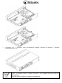
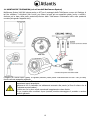
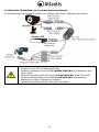
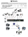
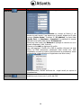
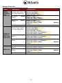
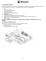
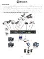
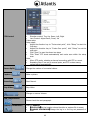
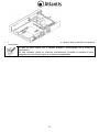
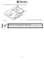
1
ITALIANO Questo prodotto è coperto da garanzia Atlantis della durata di 2 anni. Per maggiori dettagli in merito o per accedere alla documentazione completa in Italiano fare riferimento al sito www.atlantis-land.com. ENGLISH This product is covered by Atlantis 2 years warranty. For more detailed informations please refer to the web site www.atlantis-land.com. For more detailed instructions on configuring and using this device, please refer to the online manual. FRANCAIS Ce produit est couvert par une garantie Atlantis de 2 ans. Pour des informations plus détaillées, référezvous svp au site Web www.atlantis-land.com. DEUTSCH Dieses Produkt ist durch die Atlantis 2 Jahre Garantie gedeckt. Für weitere Informationen, beziehen Sie sich bitte auf Web Site www.atlantis-land.com. ESPAÑOL Este producto esta cubierto por Atlantis con una garantía de 2 años. Para mayor información diríjase a nuestro sitio Web www.atlantis-land.com. 2 ITALIANO 1. PANORAMICA DI PRODOTTO .............................................................................................................. 8 1.1 Requisiti di sistema (opzionali per l’accesso tramite WEB con Browser) ........................................... 9 1.2 CONTENUTO DELLA CONFEZIONE ................................................................................................ 9 1.3 Installazione del disco nel DVR ................................................................................................... 10 1.4 MONTAGGIO TELECAMERA (nei soli modelli NetCamera System) .................................................. 12 1.5 CABLAGGIO TELECAMERA (nei soli modelli NetCamera System) ................................................... 13 1.6 CABLAGGIO DVR ....................................................................................................................... 14 2. Funzionalità di Rete ......................................................................................................................... 15 2.1 Accesso tramite Browser ............................................................................................................ 16 2.2 Accesso tramite Mobile ............................................................................................................... 18 Setup di Mobile ............................................................................................................................... 18 Installazione e Configurazione del Client in dispositivi iPad® ed iPhone®............................................. 18 Installazione e Configurazione del Client in dispositivi Android® ......................................................... 20 2.3 Accesso tramite NetDVR ............................................................................................................. 22 3. Risoluzione dei problemi e Supporto .................................................................................................. 23 3.1 Limitazione dell’accesso. ............................................................................................................. 23 3.2 Problematiche e Domande Varie ................................................................................................. 24 3.3 Supporto Offerto....................................................................................................................... 26 APPENDICE A: CMS .............................................................................................................................. 27 APPENDICE B: CONTATTI ATTIVI ed Allarmi .......................................................................................... 33 ENGLISH 1. Product Overview ............................................................................................................................. 39 1.1 SYSTEM REQUIREMENTS (only for WEB configuration or Live View with a Browser) ...................... 39 1.2 PACKAGE CONTENTS ................................................................................................................. 40 1.3 INSTALLATION(Hard Drive) ........................................................................................................ 40 1.4 HOW TO INSTALL THE BRACKETS .............................................................................................. 42 1.5 CONNECT THE CAMERAS ........................................................................................................... 43 1.6 DVR CABLING ............................................................................................................................ 44 2. Network Access ............................................................................................................................... 45 2.1. IE Setup 46 Web Log-in(IE Browser) ................................................................................................................... 46 2.2 Mobile Phones Access ................................................................................................................ 47 Mobile Setup .................................................................................................................................. 47 IPhone/iPad ..................................................................................................................... 48 Android Mobile ................................................................................................................................ 51 3 FAQ and SUPPORT ........................................................................................................................... 56 3.1 FAQ .................................................................................................................................. 56 3.2 Support ................................................................................................................................ 58 APPENDIX A: CMS OPERATION MANUAL................................................................................................ 59 ESPANOL 1. Descripción producida ....................................................................................................................... 71 1.1 Requisitos de sistema (opcionales para acceso por WEB con IE) ................................................... 72 1.2 CONTENIDO DEL ENVASE .......................................................................................................... 72 1.3 Instalación del disco en el DVR ................................................................................................... 72 1.4 MONTAJE DE LA CÁMARA .......................................................................................................... 74 1.5 CABLEADO DE LA CÁMARA ......................................................................................................... 75 1.6 CABLEADO DVR ......................................................................................................................... 76 1.7 Soporte Técnico ......................................................................................................................... 77 DEUTSCH 1. Beschreibung Erzeugt ....................................................................................................................... 79 NetDVR V400 ................................................................................................................................ 79 NetDVR V810 ................................................................................................................................. 79 1.1 Systemanforderungen (optional für Zugriff über WEB mit IE) ....................................................... 80 3 1.2 INHALT DER VERPACKUNG ........................................................................................................ 80 1.3 Einbau der Festplatte in den DVR ................................................................................................ 80 1.4 MONTAGE DER TELEKAMERA ..................................................................................................... 82 1.5 ANSCHLIESSEN DER TELEKAMERA ............................................................................................. 83 1.6 ANSCHLIESSEN DES DIGITAL-VIDEOREKORDERS........................................................................ 84 APPENDIX APPENDIX A: TECHNICAL SPECS ........................................................................................................... 85 A09-VD400(810)(v1.0)_GX(IEDS)01 4 AVVERTENZE Abbiamo fatto di tutto al fine di evitare che nel testo, nelle immagini e nelle tabelle presenti in questo manuale, nel software e nell'hardware fossero presenti degli errori. Tuttavia, non possiamo garantire che non siano presenti errori e/o omissioni. Infine, non possiamo essere ritenuti responsabili per qualsiasi perdita, danno o incomprensione compiuti direttamente o indirettamente, come risulta dall'utilizzo del manuale, software e/o hardware. Il contenuto di questo manuale è fornito esclusivamente per uso informale, è soggetto a cambiamenti senza preavviso (a tal fine si invita a consultare il sito www.atlantisland.it o www.atlantis-land.com per reperirne gli aggiornamenti) e non deve essere interpretato come un impegno da parte di Atlantis che non si assume responsabilità per qualsiasi errore o inesattezza che possa apparire in questo manuale. Nessuna parte di questa pubblicazione può essere riprodotta o trasmessa in altra forma o con qualsiasi mezzo, elettronicamente o meccanicamente, comprese fotocopie, riproduzioni, o registrazioni in un sistema di salvataggio, oppure tradotti in altra lingua e in altra forma senza un espresso permesso scritto da parte di Atlantis. Tutti i nomi di produttori e dei prodotti e qualsiasi marchio, registrato o meno, menzionati in questo manuale sono usati al solo scopo identificativo e rimangono proprietà esclusiva dei loro rispettivi proprietari. Restrizioni di responsabilità CE/EMC Il prodotto descritto in questa guida è stato progettato, prodotto e approvato in conformità alle regole EMC ed è stato certificato per non avere limitazioni EMC. Se il prodotto fosse utilizzato con un PC/apparati non certificati, il produttore non garantisce il rispetto dei limiti EMC. Il prodotto descritto è stato costruito, prodotto e certificato in modo che i valori misurati rientrino nelle limitazioni EMC. In pratica, ed in particolari circostanze, potrebbe essere possibile che detti limiti possano essere superati se utilizzato con apparecchiature non prodotte nel rispetto della certificazione EMC. Può anche essere possibile, in alcuni casi, che i picchi di valore siano al di fuori delle tolleranze. In questo caso l’utilizzatore è responsabile della “compliance” con i limiti EMC. Il Produttore non è da ritenersi responsabile nel caso il prodotto sia utilizzato al di fuori delle limitazioni EMC. CE Mark Warning In un ambiente domestico il dispositivo può causare interferenze radio, in questo caso è opportuno prendere le adeguate contromisure. Dichiarazione di Conformità ( ) Con la presente Atlantis SpA dichiara che questo apparato è risultato conforme alla direttiva sulla bassa tensione (2006/95/EC) ed alla Direttiva sulla Comnpatibilità Elettromagnetica (2004/108/EEC) dell’Unione Europea. La dichiarazione di conformità nella sua forma completa è disponibile presso il sito www.atlantisland.com (alla pagina del prodotto) o può essere richiesta a [email protected]. apparecchiatura Importanti informazioni per il corretto riciclaggio/smaltimento di questa Il simbolo qui sotto indicato, riportato sull'apparecchiatura elettronica da Lei acquistata e/o sulla sua confezione, indica che questa apparecchiatura elettronica non potrà essere smaltita come un rifiuto qualunque ma dovrà essere oggetto di raccolta separata. Infatti i rifiuti di apparecchiatura elettroniche ed elettroniche devono essere sottoposti ad uno specifico trattamento, indispensabile per evitare la dispersione degli inquinanti contenuti all''interno delle apparecchiature stesse, a tutela dell'ambiente e della salute umana. Inoltre sarà possibile riutilizzare/riciclare parte dei materiali di cui i rifiuti di apparecchiature elettriche ed elettroniche sono composti, riducendo così l'utilizzo di risorse naturali nonché la quantità di rifiuti da smaltire. 5 Atlantis, in qualità di produttore di questa apparecchiatura, è impegnato nel finanziamento e nella gestione di attività di trattamento e recupero dei rifiuti di apparecchiature elettriche ed elettroniche compatibili con l'ambiente e con la salute umana. E' Sua responsabilità, come utilizzatore di questa apparecchiatura elettronica, provvedere al conferimento della stessa al centro di raccolta di rifiuti di apparecchiature elettriche ed elettroniche predisposto dal Suo Comune. Per maggiori informazioni sul centro di raccolta a Lei più vicino, La invitiamo a contattare i competenti uffici del Suo Comune. Qualora invece avesse deciso di acquistare una nuova apparecchiata elettronica di tipo equivalente e destinata a svolgere le stesse funzioni di quella da smaltire, potrà portare la vecchia apparecchiatura al distributore presso cui acquista la nuova. Il distributore sarà tenuto ritirare gratuitamente la vecchia apparecchiatura1. Si tenga presente che l'abbandono ed il deposito incontrollato di rifiuti sono puniti con sanzione amministrativa pecuniaria da € 103 a € 619, salvo che il fatto costituisca più grave reato. Se l'abbandono riguarda rifiuti non pericolosi od ingombranti si applica la sanzione amministrativa pecuniaria da € 25 a € 154. Il suo contributo nella raccolta differenziata dei rifiuti di apparecchiature elettriche ed elettroniche è essenziale per il raggiungimento di tutela della salute umana connessi al corretto smaltimento e recupero delle apparecchiature stesse. Il distributore non sarà tenuto a ritirare l'apparecchiatura elettronica qualora vi sia un rischio di contaminazione del personale incaricati o qualora risulti evidente che l'apparecchiatura in questione non contiene i suoi componenti essenziali o contiene rifiuti diversi da apparecchiature elettriche e/o elettroniche. NB: le informazioni sopra riportate sono redatte in conformità alla Direttiva 2002/96/CE ed al D. Lgs. 22 colari modalità di trattamento e smaltimento dei rifiuti di apparecchiature elettriche ed elettroniche (RAEE). Per ulteriori informazioni in materia, la invitiamo a consultare il nostro sito www.atlantis-land.com AVVERTENZE Non usare il dispositivo in un luogo in cui ci siano condizioni di alte temperatura ed umidità, il dispositivo potrebbe funzionare in maniera impropria e danneggiarsi. Non usare la stessa presa di corrente per connettere altri apparecchi al di fuori del dispositivo in oggetto. Il prodotto va aperto solo quando è staccato dalla rete elettrica. Non aprire mai il case del dispositivo (se non per inserire l’HDD e quando è scollegato dalla presa elettrica) né cercare di ripararlo da soli. Se il dispositivo dovesse essere troppo caldo, emmette suoni o odori particolare spegnerlo immediatamente e rivolgersi a personale qualificato. Non appoggiare il dispositivo su superfici plastiche o in legno che potrebbero non favorire lo smaltimento termico. Mettere il dispositivo su una superficie piana e stabile. Usare esclusivamente l’alimentatore fornito nella confezione, l’uso di altri alimentatori farà automaticamente decadere la garanzia. Non effettuare upgrade del firmare utilizzando apparati/client wireless ma solo wired. Questo potrebbe danneggiare il dispositivo ed invalidare la garanzia. Usare il prodotto solo in ambienti INDOOR. Non inserire nel DVR alcun oggetto metallico. Conservare la confezione con cura, va utilizzata in caso di problemi per rispedire in maniera sicura il prodotto ad Atlantis SpA. Nel dispositivo è preinstallata una batteria al litio da 3V, questa va sostituita quando (ad alimentazione assente) il dispositivo non mantiene più l’ora corretta. Scollegare l’apparato dalla presa elettrica e sostituire la batteria. 6 Lasciare almeno 10 cm liberi a lato dell’apparato e non ostruire mai le feritoie laterali e superiori. Il dispositivo contiene un HD che genera calore. La mancata dispersione porterebbe a problemi di surriscaldamento. Ogni collegamento va fatto solo ed esclusivamente a dispositivo spento. Tutte le condizioni di utilizzo, avvertenze e clausole contenute in questo manuale e nella garanzia si intendono note ed accettate. Si prega di restituire immediatamente (entro 7 giorni dall’acquisto) il prodotto qualora queste non siano accettate. La marcatura CE con il simbolo di attention Mark ( ) poste sull’etichetta di prodotto potrebbero non rispettare le dimensioni minime stabilite dalla normativa a causa delle ridotte dimensioni di quest’ultima. Atlantis invita a visitare il sito web www.atlantis-land.com alla relativa pagina di prodotto per reperire manualistica e contenuti tecnici (aggiornamenti driver e/o funzionalità, utility, support note) aggiornati. Il logo WEEE ( ) posto sull’etichetta di prodotto potrebbe non rispettare le dimensioni minime stabilite dalla normativa a causa delle ridotte dimensioni di quest’ultima. Per usufruire delle condizioni di garanzia migliorative associate al prodotto (Fast Swap, On Site e On Center) è opportuno provvedere alla registrazione dello stesso sul sito www.atlantis-land.com entro e non oltre 15 giorni dalla data di acquisto. La mancata registrazione entro il termine di sopra farà si che il prodotto sia coperto esclusivamente dalla condizioni standard di garanzia. L’utilizzo di dispositivi in grado di catturare immagini, video o voce potrebbero essere regolamentati o completamente proibiti in talune giurisdizioni. Potrebbe essere richiesta un’autorizzazione. Atlantis SpA non garantisce in alcun modo che i propri prodotti siano utilizzati in conformità con le leggi locali ed inoltre non può essere ritenuta responsabile per un uso improprio di tali dispositivi. E’ opportuno inoltre segnalare chiaramente la presenza di dispositivi capaci di catturare immagini, video o voce. Si ricorda infine di rispettare attentamente la legislazioni vigente riguardante le modalità di conservazione dei contenuti video ripresi. 7 La ringraziamo per aver scelto un apparato della famiglia NetDVR/NetCamera System, la via più semplice per la videosorveglianza. Questo documento è una guida rapida adatta a mettere il sistema in funzione velocemente, si invita a consultare il manuale completo su CDrom dove viene spiegato nel dettaglio il funzionamento dell’apparato. 1. PANORAMICA DI PRODOTTO NetCamera System V400 Kit NetCamera System V400 Kit è un sistema completo per la videosorveglianza (registrazione) adatto sia ad un utilizzo domestico che al mercato SOHO. Il DVR (registratore digitale) permette sia la visualizzazione in diretta, sul monitor collegato (tramite VGA o BNC) sino a 4 flussi (secondo il modello) video ripresi dalle Camere, che la registrazione (utilizzando il codec H.264 su disco da 3,5” interno) in modalità continua, schedulata, su evento (Motion Detection/Allarme) o forzata. La rinnovata CPU permette una registrazione a 25fps in risoluzione D1. Le 2 Camere incluse integrano un sensore CCD che, capace di funzionare anche in assenza di luminosità d’ambiente (12 LED infrarossi per funzionamento anche con 0 lux sino a 8mt), fornisce video chiari e nitidi con colori reali in ogni situazione. NetCamera System V400 Kit inoltre può essere collegato, tramite il cavo di rete, direttamente alla LAN ed essere gestito e controllato anche da remoto, in maniera semplice ed intuitiva in qualunque momento e luogo, tramite un PC o portatile collegato in Internet (o Intranet) utilizzando un qualsiasi browser (Mozilla, Internet Explorer, Chrome, Safari o Opera) web, oppure da piattaforme mobili quali Symbian, BlackBerry, Windows Mobile, iPhone, iPad ed Android(le applicazioni sono gratuite). Alternativamente, in ambienti senza LAN, una scheda 3G USB può fornire connettività al DVR. NetDVR è interfacciabile con una camera PTZ. Queste caratteristiche, unitamente al servizio Atlantis DNS dinamico gratuito per la durata di 12 mesi, rendono NetCamera System V400 Kit lo strumento ideale per il monitoraggio/videosorveglianza sia locale che remoto. NetDVR V400/V810 NetDVR è un sistema completo per la videosorveglianza (registrazione) adatto sia ad un utilizzo domestico che al mercato SOHO. NetDVR è un registratore digitale che permette sia la visualizzazione in diretta, sul monitor collegato (tramite VGA o BNC) sino a 4/8 flussi (secondo il modello) video ripresi dalle Camere, che la registrazione (utilizzando il codec H.264 su disco da 3,5” interno) in modalità continua, schedulata, su evento (Motion Detection/Allarme) o forzata. La rinnovata CPU (nel modello a 4 canali) permette una registrazione a 25fps in risoluzione D1. NetDVR inoltre può essere collegato, tramite il cavo di rete, direttamente alla LAN ed essere gestito e controllato anche da remoto, in maniera semplice ed intuitiva in qualunque momento e luogo, tramite un PC o portatile collegato in Internet (o Intranet) utilizzando un qualsiasi browser (Mozilla, Internet Explorer, Chrome, Safari o Opera) web, oppure da piattaforme mobili quali Symbian, BlackBerry, Windows Mobile, iPhone, iPad ed Android(le applicazioni sono gratuite ed incluse nel CD). Alternativamente, in ambienti senza LAN, una scheda 3G USB può fornire connettività al DVR. NetDVR è interfacciabile con una camera PTZ mentre il solo modello ad 8 canali dispone di sensori esterni (uno per canale), una Sirena. Queste caratteristiche, unitamente al servizio Atlantis DNS dinamico gratuito per la durata di 12 mesi, rendono NetDVR lo strumento ideale per il monitoraggio/videosorveglianza sia locale che remoto. Talune funzionalità (sensori esterni) sono disponibili solo su determinati modelli, si vedano le schede tecniche alla fine di questo manuale. 8 L’utilizzo di dispositivi in grado di catturare immagini, video o voce potrebbero essere regolamentati o completamente proibiti in talune giurisdizioni. Potrebbe essere richiesta un’autorizzazione. Atlantis SpA non garantisce in alcun modo che i propri prodotti siano utilizzati in conformità con le leggi locali ed inoltre non può essere ritenuta responsabile per un uso improprio di tali dispositivi. E’ opportuno inoltre segnalare chiaramente la presenza di dispositivi capaci di catturare immagini, video o voce. Si ricorda infine di rispettare attentamente la legislazioni vigente riguardante le modalità di conservazione dei contenuti video ripresi. 1.1 Requisiti di sistema (opzionali per l’accesso tramite WEB con Browser) Prima di procedere con l’installazione del prodotto verificare di disporre dei seguenti requisiti: Protocollo TCP/IP installato in ogni PC Un browser WEB quali Internet Explorer 6.0 o superiore (Active X), Safari, Mozilla Firefox, Chrome o Opera Pentium 4 1800MHz (o equivalente) con 512MB Scheda Grafica con almeno 64 MB RAM graphic cards(o scheda on-borad equivalente) Windows 2000, 2003, XP, Vista, 7 1.2 CONTENUTO DELLA CONFEZIONE Prima dell’utilizzo, verificare che la scatola contenga i seguenti elementi: NetDVR 2 TeleCamere ad Infrarossi complete di Staffe di montaggio* 2 cavi per le connessioni delle camere al DVR (18M) ed all’alimentatore* Manuale completo (Italiano ed Inglese) Mouse USB Telecomando ad infrarossi (le pile non sono incluse) Alimentatore AC-DC (12V@5A o 3A) Splitter da utilizzare per alimentare le 2 TeleCamere ed il DVR* Cd-Rom contenente manualistica multilingua (Italiano ed Inglese) e software Coupon di Garanzia Nel caso in cui il contenuto non sia quello sovradescritto, contattare il proprio rivenditore immediatamente. L'aspetto di alcuni accessori potrebbe differire leggermente da quelli mostrati nelle fotografie della scatola/manuale/scheda tecnica. Le Videocamere/Cavi/Splitter sono incluse solo nei codici KIT. L'alimentatore nei DVR singoli è di 12V@3A. Questo manuale è stato redatto per molteplici apparati. Talune caratteristiche potrebbero essere presenti solo su alcuni dispositvi. 9 1.3 Installazione del disco nel DVR Allentare le viti di bloccaggio poste ai lati e nella parte posteriore. Rimuovere delicatamente la copertura, sfilandola come da figura. Collegare il cavo di dati ed il cavo di alimentazione al disco. Installare l’ HD sulla staffa e fissarlo saldamente con le viti. 10 Controllare che i connettori siano correttamente collegati, chiudere la copertura e avvitare nuovamente con le viti. L’HDD va installato mentre il sistema è spento e non collegato ad alcuna fonte di alimentazione. Non tutti i dischi potrebbero funzionare correttamente. 11 1.4 MONTAGGIO TELECAMERA (nei soli modelli NetCamera System) NetCamera System V400 Kit integra anche un KIT per il montaggio delle TeleCamere a muro e/o Desktop. A tal fine utilizzare 3 viti/chiodi (non forniti) per fissare la base ad una superficie piatta (muro o soffitto). Avvitare poi la base nella parte posteriore/inferiore della TeleCamera. Posizionarla infine nella posizione corretta (stringendo l’apposita vite). Collegare poi l’uscita Video (giallo) e Ingresso potenza (rosso) della TeleCamera ad uno dei cavi (di 18M) forniti come da paragrafo seguente. Non collocare la Telecamera in ambienti esterni e/o in ambienti ove potrebbe essere esposta ad agenti atmosferici. Assicurarsi che il piedistallo sia saldamente ancorato alla parete (al fine di evitare che la Telecamera possa cadere). L’ottica non va in alcun modo esposta ad irraggiamento solare diretto. Il non rispetto delle condizioni sopra riportate potrebbe danneggiare il prodotto e rendere nulla la garanzia. 12 1.5 CABLAGGIO TELECAMERA (nei soli modelli NetCamera System) Lo schema seguente fornisce chiare istruzioni per il cablaggio delle diverse TeleCamere ad infrarossi. Per collegare le TeleCamere seguire la procedura seguente: Prendere un cavo SLIM (di lunghezza di 18mt) Collegarne l’estremita con la scritta TO CAMERA SIDE ONLY alla Telecamera (cavo rosso e giallo) Collegarne l’estremita gialla con la scritta TO DVR SIDE ONLY al BNC IN del DVR Collegare l’estremita rossa con la scritta TO DVR SIDE ONLY all’alimentatore Ripetere per le tutte le Telecamere la procedura Collegare l’alimentatore al DVR ed infine alla rete elettrica 13 1.6 CABLAGGIO DVR Collegare a questo punto al DVR nell’ordine: le Telecamere (BNC in, Riferimento Sezione 1.5). Altre camere possono essere acquistate separatamente. il mouse fornito. il cavo di rete, per la connessione allo switch/Router (opzionale). microfoni/speaker (opzionale). cavo VGA o BNC per la connessione ad un monitor. cavo di alimentazione. 14 2. Funzionalità di Rete Ci sono 2 differenti metodologie per accedere remotamente/localmente al DVR attraverso le funzionalità di rete: Utilizzare il browser Internet Explorer (con Active X), altri browser (Mozilla Firefoz, Opera, Safari, Chrome) con un apposito plugIN. Utilizzare iPhone/iPad/Android e (sul manuale elettronico Windows Mobile/BlackBerry/Symbian) Utilizzare NetDVR Lo schema concettuale di accesso remoto dovrebbe essere il seguente. Tutti i dispositivi ovviamente possono effettuare un accesso locale se nella LAN. 15 2.1 Accesso tramite Browser E’ possibile utilizzare Internet Explorer (IE) 6.0 o versione più recente per accedere localmente o remotamente al DVR. Questo dispositivo inoltre permette l'accesso anche da altri browser, quali Mozilla Firefox, Opera, Safari, Chrome. In questo caso è necessario installare, al primo login, un apposito plugin (NetDVRPlugin.exe). Qualora non si riuscisse ad installare il controllo ActiveX NetDVROCX.Cab (IE non potrà mostrare il video del DVR), verificare quanto segue: In Strumenti->Opzioni Internet->Protezioni selezionare Internet/Intranet ed impostare il livello Medio Alto Predefinito. In Strumenti->Blocco Popup selezionare Disattiva Blocco Popup. Per effettuare un accesso locale operare nella seguente modalità: In Main Menu->Advanced->Network è possibile conoscere l’IP assegnato al DVR (nel campo IP address) Accedere col browser web all’indirizzo di sopra e premere il tasto invio (in figura si è assunto che l’indirizzo fosse 192.168.3.103) Alla prima installazione potrebbe rendersi necessario installare alcuni componenti Active X (in IE) o NetDVRPlugin (altri Browser). La password di default è vuota, nella combo box Network selezionare LAN, scegliere in Language la lingua di visualizzazione e cliccare su Login. Il sistema supporta sino a 3 utenti contemporanei. La password di accesso di default è vuota. Spuntare la voce Open All Channels per partire con tutti i canali attivi. 16 Per effettuare un accesso remoto operare nella seguente modalità: In Main Menu->Advanced->Network è possibile conoscere l’IP assegnato al DVR (nel campo IP address). E’ opportuno assegnare un indirizzo IP statico compatibile con la propria rete LAN. In Main Menu-> Advanced->Network modificare secondo le proprie esigenze ed annotare il campo Media Port e WEB port. Accedere al Router responsabile della connettività e creare 2 Virtual Server sull’IP statico assegnato al DVR per i 2 numeri di porte di sopra (WEB Port e Media Port). Accedere col browser all’indirizzo pubblico del router*(se si è cambiato Web Port con un numero di porta diverso da 80 digitare quanto segue: http://IP Router:Web Port) e premere il tasto invio. Alla prima installazione potrebbe rendersi necessario installare alcuni componenti Active X (su IE), altri moduli (NetDVRPlugin.exe) su Mozilla FireFox, Chrome, Safari o Opera. Nel campo Media Port verificare che il numero di porta corrisponda a quella precedentemente inserita. Nella combo box Network selezionare Internet e cliccare su Login. Qualora il contratto con l’ISP non preveda un IP statico è possibile utilizzare un servizio Dynamic DNS. Si consulti l’appendice D per ulteriori dettagli in proposito. Si ricorda che il dispositivo include 12 mesi di abbonamento preconfigurato al servizio DynDNS di Atlantis SpA. La password di accesso di default è vuota. In Setup->Settings è possibile abilitare ed impostare la richiesta di password di accesso. L'accesso via Browser, quando la password è impostata, avviene solo in modalità USER. In questa modalità non si ha accesso alla sezione Setup in cui è possibile la configurazione avanzata. Network=LAN: Significa inviare in modalità CIF a 25fps. Network=INTERNET: Significa inviare in modalità CIF a 6fps. Apparirà a questo punto il Menù Principale, nella cui parte superiore è possibile accedere (come se si stessero vedendo i links in una homepage) a tutte le sezioni disponibili: PlayBack Setup (Record, Alarm, PTZ, Network, Setting, Info) LOGOUT Cliccando sulla sezione desiderata, nello spazio della homepage appariranno tutti i settaggi relativi alla configurazione della sezione scelta, oppure si apriranno tutta una serie di sottosezioni tra cui scegliere prima di avere accesso alle configurazione vere e proprie. 17 2.2 Accesso tramite Mobile Tramite l’utilizzo di questa funzionalità è possibile vedere un flusso video sul proprio dispositivo portatile da qualunque luogo ed in qualunque momento. Il DVR supporta le seguenti famiglie di dispositivi: iPhones® ed iPad Android® Setup di Mobile Prima di iniziare è opportuno configurare correttamente il DVR. Verificare i punti seguenti: Il DVR deve essere collegato, via LAN ad un dispositivo capace di offrire connettività verso internet (normalmente un router ADSL). In Main Menu->Advanced->Network è possibile conoscere l’IP assegnato al DVR (nel campo IP address). E’ opportuno assegnare un indirizzo IP statico compatibile con la propria rete LAN. Accedere a MAIN MENU->Advanced->MOBILE. E’ opportuno digitare la username e password di accesso e la porta utilizzata (di default la 15961) Server Port. Accedere al Router responsabile della connettività e creare 1 Virtual Server sull’IP statico assegnato al DVR per il numero di porta di sopra (Server Port). Accedere col client installato sul dispositivo mobile (si veda la sezione seguente) all’indirizzo pubblico del router* per visualizzare il flusso video. Passare a questo punto all’installazione/configurazione del client sul dispositivo Mobile. *Qualora il contratto con l’ISP non preveda un IP statico è possibile utilizzare un servizio Dynamic DNS. Il dispositivo incluse un servizio gratuito di 12 mesi Atlantis DNS preconfiguratoi. Si consulti l’appendice D per ulteriori dettagli in proposito. Il dispositivo è compatibile con la sola touch. versione Windows Mobile 2003 col supporto Installazione e Configurazione del Client in dispositivi iPad® ed iPhone® Tramite l’utilizzo di questa funzionalità è possibile vedere un flusso video sul proprio dispositivo portatile iPhone® o iPad® da qualunque luogo ed in qualunque momento. Visitare il website di Apple http://www.apple.com/itunes/ per scaricare ed installare iTunes. Creare un account (verranno richiesti una serie di dati personali e le informazioni circa la carta di credito per il pagamento). E' ovviamente possibile utilizzare un account già esistente. L’applicazione è gratuita. Scaricare ed installare sul proprio dispositivo l’applicazione KMEye (al momento di andare in stampa la versione disponibile è la 1.2.21 con supporto PTZ). Lanciare sul dispositivo Apple l’applicazione KMEye ( ). L’interfaccia principale di mostrata. Prima di iniziare è opportuno effettuare la configurazione di accesso. 18 KMEye verrà Cliccare sul menu setup ( ). E’ possibile, una volta effettuata la configurazione, scattare fotografie e cambiare il canale riprodotto. Verrà mostrata l’immagine sotto riportata. Cliccare su ( ).Digitare: Nome Profilo, Server IP, Porta, Username, Password. Cliccare sui canali. Cliccare poi su Save. Per accedere ad un DVR, cliccare su selezionareil DVR ed il canale). 19 e poi Se tutto è stato effettuato in maniera corretta sullo schermo del dispositivo è possibile visualizzare uno dei flussi video ripresi dalle telecamere connesse al DVR. E’ possibile cambiare il canale visualizzato. Utilizzando i bottoni disponibili nella parte inferiore dello schermo è possibile salvare l’immagine di quanto si sta visualizzando a video. La gestione di profili multipli infine permette una connessione immediata verso un determinato dispositivo. Installazione e Configurazione del Client in dispositivi Android® Tramite l’utilizzo di questa funzionalità è possibile vedere un flusso video sul proprio dispositivo portatile Android® da qualunque luogo ed in qualunque momento. Accedere all'Android Market, digitare KMEye e procedere all'installazione. In alternativa è possibile installare direttamente l'applicazione. Copiare sul terminare (o su SD Card) il file KMEye.apk (CDRom:\\A09VD400(810)\Mobile Phone \Android\KMEye.apk). Verificare che il proprio terminale sia connesso ad internet e possa scaricare il 20 software. Entrare in Programmi e selezionare l’icona E-Market. Il dispositivo effettuerà l’accesso all’E-Market. Cliccare sull’icona di ricerca ( )e cercare l’applicazione Apkinstaller. Installare quindi APKInstaller e lanciarla. Trovare il file KMEye.apk precedentemente copiato sul terminale/SD e procedere con l’installazione. Lanciare l’applicazione KMEye, i collegamenti sono solitamente conservati nella directory Programmi. Cliccare su Setup ( ) e poi su Add ( ). Digitare Device Name, Server IP, Porta, Username, Password e il numero canali. Cliccare poi su OK. In List sono conservate le ultime configurazioni utilizzate. E’ possibile, una volta effettuata la configurazione, scattare fotografie e cambiare il canale riprodotto. La gestione di profili multipli inoltre permette una connessione immediata verso un determinato dispositivo. Per collegarsi cliccare su Setup, quindi su un profilo e scegliere poi il canale da visualizzare. 21 Il client per Androis è contenuto nella cartella CDRom:\\A09-VD400(810)\Mobile Phone \Android\KMEye.apk del CDRom allegato. 2.3 Accesso tramite NetDVR E’ possibile utilizzare il client NetViewer per accedere localmente o remotamente al DVR. L’utilizzo è assolutamente identico all’accesso tramite Browser WEB. Si faccia riferimento alla sezione precedente per dettagli ulteriori. Il client NetDVR è contenuto nella cartella CDRom:\\A09VD400(810)\Utility\PC_Client del CDRom allegato. 22 3. Risoluzione dei problemi e Supporto Questo capitolo illustra come identificare e risolvere eventuali problemi riscontrati con l’utilizzo del dispositivo. 3.1 Limitazione dell’accesso. Come posso rendere sicuro l’accesso al DVR? Situazione Soluzione Accesso locale In MAIN Menu->Setup->Password è possibile definire le password di accesso diretto al DVR tramite OSD del DVR. Sono disponibili 2 profili:ADMIN ed USER. La password è composta da 6 numeri. Per richiedere la password per l'accesso locale è necessario spuntare la combo box su Password=Enable in MAIN Menu->Setup->Password. Cliccare poi su KeyLock nel menù flottante. Sono disponibili 2 profili: Admin=accesso completo al dispositivo User=accesso al solo menu Playback Le credenziali per l’accesso WEB/Locale/Mobile non sono condivise. Non è possibile impostare la password di accesso WEB, ma soltanto resettarla al valore di default (vuota) cliccando su Clear IE Password. La password di accesso LOCALE può essere cambiata, dopo aver effettuato un accesso WEB, andando in Setup-> Setting. Accesso al DVR via In MAIN Menu->Advanced->Mobile (accesso locale) è possibile impostare la piattaforma mobile USER NAME e PASSWORD (oltre che alla porta per il flusso video) utilizzata dai client (iOS, Android, Blackberry, Symbian) su piattaforma Mobile per accedere al DVR da remoto o in locale. Il valore di default prevede User Name=admin Password= Server Port=15961 Le credenziali per l’accesso WEB/Locale/Mobile non sono condivise. La password/porta di accesso Mobile può essere anche configurata via WEB, accedendo alla sezione Setup-> Network->Mobile. Accesso La password di accesso di default è vuota. In Setup-> Setting è possibile locale/remoto al abilitare ed impostare la richiesta di password di accesso. DVR via Browser Sono disponibili 2 profili: Admin=accesso completo al dispositivo User=accesso al solo menu Playback Per richiedere la password per l'accesso WEB è necessario spuntare la combo box su IE Password=ON. La password di accesso via WEB può essere cancellata, dopo aver effettuato un accesso locale, cliccando Clear IE Password in MAIN Menu->Setup>Password. Le credenziali per l’accesso WEB/Locale/Mobile non sono condivise. 23 Il sistema utilizza le porte 80(WEB) e 9000(Media) che andrebbero ruotate sul Virtual server del router per effettuare un accesso remoto. Tali porte sono liberamente configurabili, accesso via WEB, in Setup->Network>TCP/IP (Web Port, Media Port). Tali porte sono liberamente configurabili, accesso locale, in MAIN Menu>Advanced->Network (Web Port, Media Port). La password di accesso LOCALE può essere cambiata, dopo aver effettuato un accesso WEB, andando in Setup-> Setting. Non riesco ad entrare nel DVR perché non ricordo alcuna password di accesso, cosa posso fare? Situazione Soluzione Il Login fallisce (non Esiste una password generale che permette l'accesso. Digitare: 101101. ricordo più la Questa password permette sia l'accesso via WEB che locale. password di accesso)? La tabella seguente mostra, data la tipologia di accesso al dispositivo, quali password siano modificabili. Accesso Password Locale Password WEB Password Mobile Locale Impostare Password (MAIN Cancellare Password Impostare Password (MAIN Menu->Setup->Password) WEB Menu->Advanced->Mobile) (MAIN Menu->Setup>Password->Clear IE Password) WEB Impostare Password Impostare Password Impostare Password (Setup(Setup->Setting) (Setup->Setting) >Network->Mobile) Mobile N/A N/A N/A 3.2 Problematiche e Domande Varie Il DVR non rileva l’HDD, cosa posso fare? Situazione Soluzione Il DVR non rileva Verificare che i cavi siano correttamente collegati. l’HDD, cosa posso Verificare che l’HDD sia nella lista di compatibilità (i dischi nella lista sono stati fare? testati e risultati essere compatibili). L’HDD va formattato, alla prima installazione. Verificare che il cavo di alimentazione sia connesso correttamente. Il DVR non mostra alcun video a schermo, cosa posso fare? Situazione Soluzione Il DVR non mostra Verificare che i cavi siano correttamente collegati al DVR ed alle Telecamere. alcun video a Verificare che le TeleCamere siano saldamente connese ai cavi di alimentazione. schermo, cosa posso Verificare che il Monitor sia saldamente conneso ai cavi di alimentazione e VGA. fare? Verificare che il Monitor sia saldamente conneso ai cavi di alimentazione e BNC e verificare che il DVR lavori in modalità PAL. Il Buzzer del DVR suona continuamente, cosa posso fare? Situazione Soluzione Il Buzzer del DVR Le condizioni che possono far suonare il Buzzer sono: Motion Detection, Sensor, suona HDD Loss, HDD Space e Video Loss. continuamente, Verificare che in MAIN MENU->Advanced->ALARM non siano attive. cosa posso fare? 24 L’interfaccia RS485 per il controllo delle PTZ non funziona correttamente, cosa posso fare? Situazione Soluzione L’interfaccia RS485 IL DVR al momento attuale supporta propriamente questa funzionalità, controllare per il controllo delle comunque eventuali upgrade di firmware successivi sul sito www.atlantis-land.com. PTZ non funziona Verificare comunque che il Protocolo, Baud Rate e gli altri settaggi della PTZ siano correttamente, cosa propriamente impostati nel DVR. posso fare? Verificare che il cavo di collegamento sia saldamente connesso. Collegare solo a dispositivo spento. Tenere presente le seguenti informazioni circa il collegamento: A=+ B=Internet Explorer non riesce a visualizzare il flusso video. Cosa posso fare? Situazione Soluzione Internet Explorer Il problema dovrebbe essere generato da versioni inconngruenti di OCX. E’ non riesce a sufficiente forzare la rimozione di questi moduli e riavviare poi IE. visualizzare il flusso Il dispositivo, tramite un appositoplugin, permette la visualizzazione di flussi video video. anche con Mozilla Firefox, Chrome, Safari ed Opera. Accesso Remoto al DVR con Browser/NetDVR e/o CMS. Situazione Soluzione Per effettuare un In Main Menu->Advanced->Network è possibile conoscere l’IP assegnato accesso remoto al DVR (nel campo IP address). E’ opportuno assegnare un indirizzo IP operare nella statico compatibile con la propria rete LAN. seguente modalità: In Main Menu-> Advanced->Network modificare secondo le proprie esigenze ed annotare il campo Media Port e WEB port. Accedere al Router responsabile della connettività e creare 2 Virtual Server sull’IP statico assegnato al DVR per i 2 numeri di porte di sopra (WEB Port e Media Port). Accedere col browser all’indirizzo pubblico del router*(se si è cambiato Web Port con un numero di porta diverso da 80 digitare quanto segue: http://IP Router:Web Port) e premere il tasto invio. Alla prima installazione potrebbe rendersi necessario installare alcuni componenti Active X (su IE), altri moduli (NetDVRPlugin.exe) su Mozilla FireFox, Chrome, Safari o Opera. Nel campo Media Port verificare che il numero di porta corrisponda a quella precedentemente inserita. Nella combo box Network selezionare Internet e cliccare su Login. La password di accesso di default è vuota. In Setup->Settings è possibile abilitare ed impostare la richiesta di password di accesso (l'accesso via browser/NEtViewer avviene solo in modalità USER, quando viene forzata la password di accesso) mentre col CMS è possibile accedere come USER o ADMIN. Accesso Remoto al DVR con Mobile. Situazione Soluzione Per effettuare un In Main Menu->Advanced->Network è possibile conoscere l’IP assegnato accesso remoto al DVR (nel campo IP address). E’ opportuno assegnare un indirizzo IP operare nella statico compatibile con la propria rete LAN. seguente modalità: In Main Menu-> Advanced->Mobile modificare secondo le proprie esigenze ed annotare il campo Server Port. Accedere al Router responsabile della connettività e creare 1 Virtual Server sull’IP statico assegnato al DVR per il numero di porte di sopra (Server 25 Port). Accedere col dispositivo Mobile all’indirizzo pubblico del router*. La password di accesso di default è vuota. In Main Menu-> Advanced>Mobile è possibile abilitare la USER/PAssword relativa all'accesso mobile. 3.3 Supporto Offerto Per qualunque altro problema o dubbio sul funzionamento del prodotto, è possibile contattare il servizio di assistenza tecnica Atlantis tramite l’apertura di un ticket on-line sul portale http://www.atlantisland.com/ita/supporto.php. Nel caso non fosse possibile l’accesso al portale di supporto, è altresì possibile richiedere assistenza telefonica al numero 02/ 78.62.64.37 (consultare il sito per verificare gli orari in cui il servizio viene erogato). Per esporre eventuali richieste di supporto prevendita o richieste di contatto , si invita ad utilizzare gli indirizzi mail [email protected] oppure [email protected]. Atlantis SpA Via S. Antonio, 8/10 20020 Lainate (MI) Fax: +39.02.78.62.64.39 Website: http://www.atlantis-land.com Email: [email protected] 26 APPENDICE A: CMS Il CMS è un software, disponibile per ambienti Windows, che permette il collegamento remoto/locale ad uno o più DVR in maniera rapida ed intuitiva. Di seguito le principali caratteristiche: Supporta connessioni ad un vasto numero di DVR (sino a 16) e sino a 64 canali video simultanei Permette di visualizzare il singolo flusso video di diversi DVR Supporta registrazione, playback e backup remoto Permette la configurazione remota dell'apparato Permette controllo PTZ Supporto cattura immagini e registrazione in locale Supporto ScreenLock Requisit Hardware/Software Almeno un Pentium 4 o un AMD ad almeno 3Ghz Directx 9.0 o superiori 1 GB di memoria Windows 7/Vista (32/64) Software Una volta installato verrà creata una cartella DVRCMS. Selezionare l'icona DVRCMS ( partire il software in questione. Al primo avvio verrà chiesto di creare un profilo utente. ) per far Digitare Username e Password (2 volte per sicurezza, sono ammessi sino a 15 caratteri) e poi selezionare il linguaggio dalla combo box. Cliccare OK per effettuare il login. La versione contenuta nel CD è la 1.1.0.7. Nel caso una versione precedente sia stata già installata e poi rimossa è opportuno verificare che il file dei settaggi sia stato concellato (:Program Files\DVRCMS\user.cfg). Installare DVRCMS tramite la pagina WEB o accedendo direttamente al file (CDRom:\\A09-VD400(810)\Utility\CMS). Una volta partita l’installazione, seguire le istruzioni a video. 27 Effettuato il Login il sistema visualizzerà la schermata sotto riportata. Una volta configurati i flussi video, questi tramite Drag'n'Drop possono essere liberamente posizionati nella griglia dei canali. Una volta selezionato un flusso video, il contorno diverrà rosso: Nella status BAR sono riportati informazioni circa il flusso video (DVR, IP, porta) Capture, Recording, Volume Control, PTZ sono attivi per il flusso selezionato Un doppio click su un flusso video lo ingrandisce sino ad occupare l'intera area della griglia dei canali, un altro doppio click lo ridimensiona sino all'occupazione originale. Un massimo di 64 canali contemporanei sono gestibili dal CMS. Sino a 16 DVR possono essere connessi (con le limitazioni in visualizzazione di 64 canali). 28 Funzione Add DVR( ) Significato Cliccare per accedere alla schermata di aggiunta di un DVR. Selezionare nella Combo Box Device un numero di Device (1 per device sino ad 8 canali, 2 per device con 16 canali), digitare poi il nome univoco (Device Name), l'indirizzo IP (IP Address), la porta Video (Media Port), la Username e Password (le password di accesso utilizzate sono quelle della sezione IE Password). Slezionare nella combo box Network la tipologia di network con cui si accede all'apparato (LAN, Internet). Cliccare poi su Add per aggiunger eil profilo. Una volta aggiunto il Profilo di un DVR è possibile (cliccando col tasto destro sul DVR selezionato) selezionare dalla combo box, sotto visualizzata, una serie di opzioni (aprire/bloccare la riproduzione, creare un'istantanea, iniziare/bloccare la registrazione dei flussi video): Del DVR( ) Alternativamente, cliccare sull'icona dei singoli canali per aprirne la visualizzazione. Selezionare in Device List il nome del DVR da rimuovere e cliccare su quest'icona per rimuoverne il profilo dal CMS. 29 In questa sezione è possibile gestire pienamente le varie telecamere motorizzate (puntamento, Zoom/Focus/Iris) connesse ai DVR. Selezionare il canale connesso alla PTZ. PTZ Control Screen Split ( Capture ( ) ) Controlli BASE Direzione: Destra, Sinistra, Alto e Basso. Controlli ottici: Zoom, Focus e IRIS. Preset Setup steps: Selezionare una direzione (Controlli Base) di puntamento della Camera, slezionare un numero Identificativo e cliccare su "Set" Ripetere il punto di sopra spostando la camera con i controlli di direzione e cliccando su "Set" (l'identificativo verrà incrementato). Cliccare su "Save". Selezionare l'identificativo e cliccare su "Recall" per richiamare la posizione memorizzata. Cruise setup Setup steps: Selezionare una direzione (Controlli Base) di puntamento iniziale della Camera come “Cruise start point”, e cliccare su "Set" Selezionare una direzione (Controlli Base) di puntamento finale della Camera come “Cruise over point”, e cliccare su "Set" Cliccare su "Save" Cliccare su "Start" per far eseguire alla Camera motorizzata la sequenza di movimenti appena impostata. Nota: Ripetendo gli step di sopra è possibile memorizzare diversi percorsi toccati dal movimento della PTZ. Cliccare Clear per cancellare le memorizzazioni dei percorsi fatti. Cliccando su quest'icona si aprirà una combo box contenente la modalità di visualizzazione dei canali sul display. E' possibile passare dalla modalità monocanale sino a quella a 64 canali (8x8) contemporanei a video provenienti da diversi DVR. Selezionare la tipologia di griglia desiderata nella combo box visualizzata alla pressione dell'icona ). Permette di effettuare un'istantanea del flusso video selezionato (contorno rosso). Tale file, salvato nella directory esplicitata in System->General->File Path, ha un'estensione BMP ed una risoluzione D1. Il sistema genererà una cartella: File Path\Indirizzo 30 IP\Capture\ID Canale\DataOra.Bmp. E' inoltre possibile effettuare un'istantanea di TUTTI i flussi video visualizzati (selezionare Capture ALL nella combo box visualizzata alla Recording( pressione dell'icona ). Permette di effettuare la registrazione del flusso video selezionato (contorno rosso). Tale file, salvato nella directory esplicitata in System->General->File Path, ha un'estensione 264 ed una risoluzione D1/HD1 o CIF. Il sistema genererà una cartella: File Path\Indirizzo IP\Record\Data\ID Canale\DataOra.264. E' inoltre possibile effettuare una registrazione di tutti i flussi video visualizzati (selezionare Capture ALL nella combo box visualizzata alla ) pressione dell'icona Stop Video( Volume ( ( Permette di bloccare la visualizzazione dei flussi video. ) ) DVR Configuration ) ). E' possibile impostare il livello del volume o cliccando 2 volte sull'icona volume ( ) disabilitarlo completamente. E' possibile, usando il CMS, avere accesso completo alla configurazione del DVR. Per fare questo cliccare sull'icona e selezionare nella combo box Device il nome del DVR (DVR List) che si desidera configurare. La configurazione è esattamente la stessa che si avrebbe con un accesso locale/WEB. Si consulti il capitolo 4 per dettagli ulteriori. 31 Si consiglia di utilizzare l'accesso WEB/Diretto per effettuare la configurazione del DVR. Taluni parametri potrebbero non essere supportati dal CMS. System Configuration ( ) PlayBack( E' possibile accedere alla configurazione del CMS. General: File Path e Password di accesso. Device: E' possibile modificare facilmente i parametri dei DVR inseriti nella Device List. Account: Creare/Disabilitare/Cancellare account per l'accesso al CMS. Un massimo di 10 account sono permessi. E' possibile visualizzare o fare il backup dei file video presenti sui vari ) DVR. Per fare questo cliccare sull'icona e selezionare nella combo box Device il nome del DVR (DVR List) di cui si desidera effettuare il backup dei file video. Si consulti il capitolo 5 per dettagli ulteriori. Lock ( ) Cliccare sull'icona per bloccare il sistema. Per avere nuovamente accesso al CMS cliccare su 32 e rieffettuare il Login. APPENDICE B: CONTATTI ATTIVI ed Allarmi Alcuni modelli di DVR integrano avanzate funzioni di commutazione che rendono possibili la ricezione/invio di segnali ad altri dispositivi di allarme (rilevatori volumetrici, PIR o sirene). Si veda nel disegno seguente uno schema di installazione tipico. Come si può vedere il dispositivo integra, nella parte posteriore: 2 PIN per la connessione verso una sirena esterna alimentata N prese di terra (G in verde) N ingressi programmabili (proporzionali al numero di canali) SIREN In sostanza è possibile collegare a questi PIN il circuito da controllare, dotato della propria alimentazione. Gli eveni responsabili della chiusura del circuito sono: Motion Detection/Cambio di stato di un Sensore. Impostare: Advanced->Alarm->Alarm Manage Output=da 10s a 60s. 33 Record->CH(X)=ON Record->Rec Mode=By Timer Record->Schedule=Alarm Advanced->MD->CH(X)=ON Alarm->I/O Alarm(x)=NO/NC EXTERNAL SENSORS I sensori esterni, in numero pari ai canali, possono essere collegati al dispositivo. Possono cambiare lo stato del circuito in ingresso (può essere normalmente aperto, chiuso o disattivato) facendo scattare un trigger capace di generare l'inizio della registrazione del canale video equivalente, l'invio di una mail o l'attivazione di una sirena (interna o esterna). Impostare: Advanced->Alarm->Alarm Manage Output=da 10s a 60s. Advanced->Alarm->Buzzer= da 10s a 60s. Record->CH(X)=ON Advanced->Alarm->I/O Alarm(x)=NO/NC 34 Sinottico Riassuntivo Il sinottico seguente permette di avere un Evento Conseguenze Configurazione Trigger su Visualizzazione su Record->CH(X)=ON Motion schermo della lettera R Record->Rec Mode=By Timer Detection con inizio registrazione Record->Schedule=Alarm di un Advanced->MD->CH(X)=ON canale (X) Attivazione Sirena Record->CH(X)=ON esterna Advanced->MD->CH(X)=ON Advanced->Alarm->Buzzer=10s(almeno) Attivazione Buzzer Record->CH(X)=ON interno Advanced->MD->CH(X)=ON Advanced->Alarm->Alarm Output=10s(almeno) Invio Mail Advanced->Alarm->Email Setup Visualizzazione su Record->CH(X)=ON schermo della lettera I Record->Rec Mode=By Timer con inizio registrazione Record->Schedule=Alarm Advanced->MD->CH(X)=ON Advanced->Alarm->I/O Alarm(x)=NO/NC Advanced->Alarm->Buzzer=10s(almeno) Trigger su Attivazione Sirena Record->CH(X)=ON cambio di esterna Advanced->Alarm->I/O Alarm(x)=NO/NC stato di un Advanced->Alarm->Buzzer=10s(almeno) sensore(X) Attivazione Buzzer Record->CH(X)=ON interno Advanced->Alarm->I/O Alarm(x)=NO/NC Advanced->Alarm->Alarm Output=10s(almeno) Invio Mail Advanced->Alarm->Email Setup Attivazione Sirena Record->CH(X)=ON esterna Advanced->Alarm->Buzzer=10s(almeno) Attivazione Buzzer Record->CH(X)=ON Video Loss interno Advanced->Alarm->Alarm Output=10s(almeno) Invio Mail Advanced->Alarm->Email Setup 35 Manage Manage Manage Copyright Statement No part of this publication may be reproduced, stored in a retrieval system, or transmitted in any form or by any means, whether electronic, mechanical, photocopying, recording or otherwise without the prior writing of the publisher. Windows™ 98SE/2000/ME/XP/VISTA are trademarks of Microsoft® Corp. Pentium is trademark of Intel. All copyright reserved. The Atlantis logo is a registered trademark of Atlantis. All other names mentioned mat be trademarks or registered trademarks of their respective owners. Subject to change without notice. No liability for technical errors and/or omissions. Regulatory Information/disclaimers Installation and use of this Wireless LAN device must be in strict accordance with the instructions included in the user documentation provided with the product. Any changes or modifications made to this device that are not expressly approved by the manufacturer may void the user’s authority to operate the equipment. The Manufacturer is not responsible for any radio or television interference caused by unauthorized modification of this device, of the substitution or attachment. Manufacturer and its authorized resellers or distributors will assume no liability for any damage or violation of government regulations arising from failing to comply with these guidelines. CE Mark Warning In a domestic environment, this product may cause radio interference, in which case the user may be required to take adequate measures. CE/EMC Restriction of Liability The product described in this handbook was designed, produced and approved according to the EMCregulations and is certified to be within EMC limitations. If the product is used in an uncertified PC, the manufacturer undertakes no warranty in respect to the EMC limits. The described product in this handbook was constructed, produced and certified so that the measured values are within EMC limitations. In practice and under special circumstances, it may be possible, that the product may be outside of the given limits if it is used in a PC that is not produced under EMC certification. It is also possible in certain cases and under special circumstances, which the given EMC peak values will become out of tolerance. In these cases, the user himself is responsible for compliance with the EMC limits. Declaration of Conformity ( ) Hereby, Atlantis SpA, declares that this device is in compliance with the essential requirements and other relevant provisions of Directive 2004/108/EC “Electromagnetic Compatibility” and 2006/95/EC (Low Voltage Directive) within CE Marking Requirement. SAFETY INSTRUCTIONS Electric shock can be avoided. Follow the recommended practices listed below. Faulty installation, improper grounding, and incorrect operation and maintenance of electrical equipment are always sources of danger. Do Not try to install equipment outdoor, when the wind and rain is strong. Do Not install or remove equipment outdoor ,when the weather is raining. Do Not try to install or operate any equipment , when the thunderstorm happened. Always Ground all electrical equipment and the work platform. Prevent accidental electrical shocks. Connect power source, control cabinets, and work platform to an approved electrical ground. Always use the correct cable size. 36 Sustained overloading will cause cable failure and result in possible electrical shock or fire hazard. Work cable should be the same rating as the torch cable or factory . Always keep cables and connectors in good condition. Improper or worn electrical connections can cause short circuits and can increase the chance of an electrical shock. Do not use worn, damaged, or bare cables. Always avoid open-circuit voltage. The added voltages increase the severity of the shock hazard. Always wear insulated gloves while you adjust equipments. Power should be shut off and insulated gloves should be worn when making any equipment adjustment to assure shock protection. Always wear protective clothing such as long sleeve shorts while you are installing or removing equipments. Always Wear high, snug fitting shoes. Always Wear clean clothes without grease or oil. Do not wear clothing that has been stained with oil and grease. It may burn if ignited by the heat of the arc. Protect neighboring workers from exposure to arc radiation. Always Wear long trousers or jeans while you are installing or removing equipments. Always wear safety helmet or hard head and safety shoes before work. Always keep the equipments in dry places. Always wear safety harnesses/belt while you work in high places. Always wear dry clothing and avoid moisture and water. Always wear Public Safety Vest , while you work at night. Make sure all electrical connections are tight, clean, and dry. Make sure that you are well insulated and eliminate the electric static charge. Always wear dry gloves, rubber-soled shoes, or stand on a dry board or platform. Always Follow recognized safety standards. Always wear correct eye, ear, and body protection. Always have second person on-site, while you work in the darkness places, poor ventilation places and high places. Make sure that you are well protected against arc flashes, mechanical injury, or other mishaps. Make sure that the polarity of wire is correct, before installing equipments. Always handle equipment with care. Do Not block the ventilation of equipment. Do Not put the magnetic parts around the Equipment. Do Not put the objects on top of equipment. Important information for the correct recycle/treatment procedures of this equipment The crossed-out wheeled bin symbol printed on the unit label or unit packaging indicates that this equipment must not be disposed of as unsorted municipal waste but it should be collected separately. The waste of electric and electronic equipment must be treated separately, in order to ensure that hazardous materials contained inside the equipment are not buried thereby providing potential future problems for the environment and human health. Moreover, it will be possible to reuse and recycle some parts of the waste of electric and electronic equipment, contributing to reduce the quantities of waste to be disposed of and the depletion of natural resources. As user of this equipment, you are responsible to return this waste of electronic equipment to an authorised collection facility set up by your Municipality. More detailed information on your nearest collection centre can be obtained from your Municipality or from other competent local entities. 37 If you are replacing the old equipment with a new equivalent product, the distributor must take-back the old equipment free of charge on a one-to one basis as long as the equipment is of equivalent type and fulfilled the same functions as the supplied equipment. Your rôle in participating to the separate collection of waste of electric and electronic equipment is essential to ensure that environmental protection and human health objectives connected to a responsible treatment and recycling activities are achieved. PS.: The above mentioned information are reported herewith in compliance with Directive 2002/96/CE, which requires a separate collection system and specific treatment and disposal procedures for the waste of electric and electronic equipments (WEEE). For further and more detailed information, we invite you to visit our website at www.atlantis-land.com CE Logo with attention Mark ( ) aren’t fully compliant with minimum dimensions requirement to European Directive due to limited sticker area. WEEE BIN Logo ( ) isn’t fully compliant with minimum dimensions requirement to European Directive due to limited sticker area. Atlantis suggest to vistit the web site www.atlantis-land.com in order to retrieve update manual, techsheet and driver. Before starting, take a few minutes to read this manual. Read all of instructions and save this manual for later reference. 38 Thank You for choosing an Atlantis Product. For more detailed instructions on configuring and using the NetCamera System, please refer to the online manual into CD. 1. Product Overview NetCamera System V400 Kit NetCamera System is a complete solution (with standalone 4Ch DVR and 2 IR Cameras) for local/remote video surveillance, designed to operate in every working environment (domestic or SoHo). DVR is able to playback locally, on the connected monitor (VGA or 1 x BNC), up to 4 channels and is able to record (always, motion detection, manual, time schedule or external sensors) on the internal 3,5” HDD, using H.264 codec. The CCD sensor, able to work also with a low light intensity of the environment, provides clear and tidy videos with real colours in each situation (12 IR LEDs down to 0 Lux up to 8 mt). The new CPU is able to record in Full D1. Finally, it can be remotely managed and controlled at any moment and place, in a simply and intuitive way, via PC or notebook connected to the Internet (or Intranet) by using any web browser (Mozilla, Internet Explorer, Chrome, Safari or Opera) or mobile devices (Symbian, Windows Mobile, BlackBerry, iPhone or iPad). Using an optional USB external 3G modem the device is able to send email also without a LAN connection. This device can be connected with: 1 PTZ Camera (RS485). These features, with the included 12 months free Atlantis DynDNS subscription, make Camera System the ideal tool for local/remote monitoring/video surveillance. NetDVR V400/V810 NetDVR is able to playback locally, on the connected monitor (VGA or 1 x BNC), up to 4/8 channels and is able to record (always, motion detection, manual, time schedule or external sensors) on the internal 3,5” HDD, using H.264 codec. The new CPU (NetDVR V400) is able to record in Full D1. Finally, it can be remotely managed and controlled at any moment and place, in a simply and intuitive way, via PC or notebook connected to the Internet (or Intranet) by using any web browser (Mozilla, Internet Explorer, Chrome, Safari or Opera) or mobile devices (Symbian, Windows Mobile, BlackBerry, iPhone or iPad). Using an optional USB external 3G modem the device is able to send email also without a LAN connection. NetDVR V400: This device can be connected with 1 PTZ Camera (RS485). NetDVR V810: This device can be connected with 1 PTZ Camera (RS485), 8 External Sensors and 1 External Siren. These features, with the included 12 months free Atlantis DynDNS subscription, make NetDVR the ideal tool for local/remote monitoring/video surveillance. Use of audio or video equipment for recording the image or voice of aperson without their knowledge and consent is prohibited in certain states orjurisdictions. Nothing herein represents a warranty or representation that the Atlantis product provided herein is suitable for the end-user’s intended use under the applicable laws of his or her state. Atlantis SpA disclaims any liability whats oever for any end-user use of the Atlantis product, which fails to comply with applicable state, local, or federal laws. 1.1 SYSTEM REQUIREMENTS (only for WEB configuration or Live View with a Browser) Before installing Router, your PC should meet the following: TCP/IP protocol must be installed on each PC Web browser, such as Microsoft Internet Explorer 6.0 or later (Active X) Mozilla, Chrome, Safari or Opera Pentium 4 1800MHz (or equivalent AMD) with 512MB Graphic Card: 64 MB RAM graphic cards(or equivalent on-board graphic cards) Windows2000, 2003, XP, Vista, 7 39 1.2 PACKAGE CONTENTS Unpack the package and check all the items carefully. Also, keep the box and packing materials in case you need to ship the unit in the future. The package should contain the following items: DVR 2 Cameras (DVR Kit) 2 Slim Cable (18M) (DVR Kit) 2 Brackets (DVR Kit) Quick Start Guide (English, Italian) USB Mouse IR Remote Controller Adapter AC-DC (12V@3A) and Power Cable for DVR Adapter AC-DC (12V@5A) with 4 Way Power Cable Splitter for Cameras (DVR Kit) Cd-Rom with manual, Utility, Software Warranty Card If any item contained is damaged or missing, please contact your local dealer as soon as possible. 1.3 INSTALLATION(Hard Drive) Please do NOT install or uninstall hard drive while DVR is running. Loosen the screws in the left and right sides. Remove the cover Connect data cord and power cable. Install HDD on the bracket, fixed with screws firmly. 40 Check if the connectors are properly connected and there is no problem with wiring and close up cover, and fix it with screws. 41 1.4 HOW TO INSTALL THE BRACKETS Hold the first Bracket onto the wall or ceiling Fix the screws into place 42 1.5 CONNECT THE CAMERAS Connect the 18mt camera cable to a camera’s video output terminal (BNC connector) & power input terminal (RCA jack). Connect another BNC connector of the 18mt camera cable to the BNC Video Input terminal on the rear panel of the DVR. Connect the 4-way camera DC power splitter to the RCA jack of the camera cable. Connect the 4-way camera DC power splitter to the camera power supply. Connect the DVR power supply to the DC input jack on the rear panel of the DVR. 43 1.6 DVR CABLING Connect a video cable with BNC connectors from your monitor to the BNC video output ports on the rear panel of your DVR . Connect a VGA cord (not included) from your monitor to the VGA output on the rear panel of your DVR (or use BNC Output). Connect the USB mouse to the USB slot for mouse on the rear panel of the DVR. Connect one end of the network cable (not included) to RJ-45 port on the rear panel of the DVR. Connect another end of the network cable to your router, modem or other network connection device. Plug in both of the Camera & DVR power supply to an open outlet. 44 2. Network Access There are 3 different methods to remote access the DVR via network: Internet Explorer Browser (IE with Active X) or Mozilla Firefox, Opera, Safari or Chrome. Mobile phones (iPhone/iPad/BlackBerry/Symbian/Android and Windows Mobile) NetDVR (windows) 45 2.1. IE Setup Web Log-in(IE Browser) Open the web browser, enter the local port IP address of this device (Main Menu->Advanced>Network), and click Go to get the login page. Default password is empty. Click to Login. NetDVR allow you 3 users on-line simultaneously. The deault password is empty. Network=LAN: If the computer and DVR are in the same LAN, choose “LAN” mode .In this mode, the image video transmission format is CIF and the frame rate is 25fps. Network=INTERNET: If the computer and DVR are in different LAN, choose “Internet”. In this mode, the image video transmission format is CIF and the frame rate is 6fps. 46 2.2 Mobile Phones Access The DVR is currently compatible with mobile phones running Windows Mobile, Symbian, iPhone, Blackberry and Android operating system. Due to the model of mobile phone is variety, so we only provide 1 model for your reference, if you have any question of your mobile phone ,please go to the website: When your DVR is connecting internet through router, you need to forward the port at the virtual server option of your router. For more information, please refer to Appendix A(mobile) in this section. Mobile Setup Before viewing the live image of DVR from mobile phones, you need to set the settings first. Also make sure that your DVR has connected to Internet. In this page (Main Menu->Advanced->Mobile) You can change username/password/Server Port: USER NAME USER PASSWORD SERVER PORT All Functions The login user name of DVR. Default value is admin. The login Password of DVR. Default value is empty. Mobile monitoring port. Setting range is between 1024 and 65535. Please note that the server port of DVR must with the same port of mobile. Default is 15961. You also need to forward this port at the virtual server option of your router. 47 IPhone/iPad Download iTunes Visit Apple website http://www.apple.com/itunes/ to download & install the iTunes. Step 1. Click search” column . and then Key-in the characters “KMEye” in the” For connecting cable, please contact your local i-Phone service. Or go to i-phone website for support : http://www.apple.com/support/iphone/ Step 2. Download and install the “KMEye” program to your mobile by connecting cable. Step 3. After finishing installation, “ KMEye” icon will be displayed to mobile phone interface. 48 Step 4. Click , “ KMEye” icon to enter the main screen, as below: We have introduced Monitor point setting in the previous Symbian and Windows system setting. The setting method for iPhone is same as the Symbian and Windows system. Please refer to the previous section. Step5. Setting the connecting information of DVR. Server IP All Functions Indicate that public IP address connected to DVR or dynamic domain 49 Port User ID Password name used by DVR Indicate the server port which has been set to your DVR. Indicate that the user name which have been set on DVR menu. Indicate that the password which has been set on DVR- menu. Step 6. Click “ ” button, to back to main screen. Step 7. Click “Play & Pause ” button, to view videos, remotely . 50 Android Mobile Please make sure that the software is compatible with your Android Mobile. Step 1 If You want download directly from the market please jump to Step 10 otherwise make sure your mobile have been connected to network and could download the software. Step 2. Enter into “Program” option and highlight “E-market” icon . Step 3. Enter into the “E-market” interface . Step 4. Click program. icon on the upper right corner and key-in“Apkinstaller” to search the Apkinstaller 51 Step 5. Highlight and install the program which was searched by system. Step 6. Proceeding to the next step for installation. Step 7. Enter into “Program” file and click “ ApkInstaller” icon. 52 Step 8. Find the “KMEyeapk” file you would like VD400(810)\Utilit\Mobile Phone\Android\KMEye.apk). Step 9. Click the software to install to your phone. Step 10. Directly download KMEye from market. Step 11. Enter into “Program” option to click “KMEye” icon . 53 to install (CDRom:\A09- Step 12. Enter into “KMEye” main screen. . Click “Setup ” button, to set the “Device info All Functions Device Name Name Adresss Indicate that public IP address connected to DVR or dynamic domain name used by DVR Port Indicate the server port which has been set to your DVR. User name Indicate that the user name which have been set on DVR menu. Password Indicate that the password which has been set on DVR- menu. Max Channel Select the channels connected to the DVR. OK Click this button for confirm all settings. Cancel Click this button for cancel all data. Step 13. Click Setup, then Select a profile and select the bumber of the channel you want watch. 54 When your DVR is connecting internet through router, you need to forward the port at the virtual server option of your router. For more information, please refer to Appendix in this section. 55 3 FAQ and SUPPORT 3.1 FAQ What can I do if the system does not detect the HDD? Situation Solution What can I do if the Check the data and power cables and make sure they are securely system does not connected. detect the HDD? For new H.D.D, you have to format it first. Make sure that the power of adaptor is correct, 12V/5A. We have changed the password but do not remember the new password, how can we access the system? Situation Solution We have changed If you forget system password, enter 101101 into the password field to reset the the password but do password. not remember the new password, how can we access the system? We are not getting any Situation We are not getting any video signal on the DVR, what is wrong video signal on the DVR, what is wrong? Solution Check to make sure the cables are securely connected to the BNC ports on the DVR. You can also try another cable to make sure there is not a problem with the cable. Make sure you have selected the correct video format for your country (NTSC or PAL), is the USA we use NTSC. Can the DVR have problems if it gets too hot, how can I prevent this? Situation Solution Can the DVR have The DVR has a fan to help it dissipate heat while it is working. Please place the problems if it gets DVR in a place where there is good air circulation and away from high too hot, how can I temperatures to increase stability and life of the DVR. prevent this? My remote control does not work when the DVR is in Live mode but the front panel buttons are working, what is wrong? Situation Solution My remote control Make sure nothing is blocking in front of LED on the remote or the receiver on the does not work when DVR, if both are ok, check the batteries. the DVR is in Live mode but the front panel buttons are working, what is wrong? Can I use the hard drive from my PC in the DVR? Situation Solution Can I use the hard You can if the hard drive is the same type and the size is supported by the DVR. If drive from my PC in you install it in the DVR it will be formatted for use in the DVR and the PC will not the DVR? be able to read it. 56 Do I have to stop recording to playback files on the DVR? Situation Solution Do I have to stop No you do not have to stop recording, the DVR will support both functions at the recording to same time. playback files on the DVR? Can I erase files from the hard drive of the DVR? Situation Solution Can I erase files You can not erase individual file, you would need to format the hard drive which from the hard drive will erase all of the files. of the DVR? Why can’t I log-in to the Net-viewer program? Situation Solution Why can’t I log-in to Please verify that the Net mode is correct, the cable to the RJ-45 port is well the Net-viewer connected to the DVR and the router, and that you are using the correct password. program? We have attached a PTZ camera but can not control it, what is wrong? Situation Solution We have attached a Verify that the Protocol, baud rate, address, and other settings on the PTZ camera PTZ camera but can match the settings you have put into the DVR. Make sure the data cables are not control it, what attached firmly to the RS485 port on the DVR. is wrong? Why does the Buzzer keep sounding? Situation Solution Why does the Please check to see if motion detection is on and the system has detected motion, Buzzer keep make sure the hard drive is being detected and has sufficient space available and sounding? that none of your cameras have lost video. You can turn off the buzzer in the Alarm setup option. I can connect to IE Browser, but how can my IE interface is a little bit difference? Situation Solution Why can’t I log-in to The reason is the OCX of IE Browser which memorized other version IE interface, the Net-DVR so your IE browser was conflict with other version. There’s the solution: program? 57 3.2 Support For technical questions and support, please contact our help-desk by ticket on http://www.atlantisland.com/ita/supporto.php. For generic informations, please send an e-mail to [email protected]. For presales informations, please send an e-mail to [email protected]. Atlantis SpA Via S. Antonio, 8/10 20020 Lainate (MI) Italy Fax: +39.02.78.62.64.39 Website: http://www.atlantis-land.com Email: [email protected] 58 APPENDIX A: CMS OPERATION MANUAL This software can be directly connected to the DVR through the Internet without the support of intermediate server. It is user-friendly and can be connected rapidly. Main functions: Support connection to 16 DVRs at most and 64 channels video simultaneously Support visit of any video channel of different DVRs and screen dragging and random combination Support remote recording playback and backup Support off-line playing and smooth playing of backup video Support remote parameters configuration Support remote control of PTZ Support local capture and recording Support screen lock Installation requirements: At least Intel Pentium 4 or AMD Athlon 3000+ processor; Multimedia: above DirectX 9.0; Recommended internal memory: above 1 GB. Windows 7/Vista (32-64bit) Software Installation Procedures: Double click and run the file “DVRCMS.msi” from the CD or Web Interface. Select “Next >” Select the installation position and press “Next >”, and then start to install, and finallly click “close” to finish the installation. If this software has already been installed, please uninstall the ear before installation. The release into CD is 1.1.0.7. If the earlier version of this software has already been installed, please delete the “user.cfg” under the installation menu manually, the software is default installed in (:Program Files\DVRCMS\user.cfg). Start the software Double click the desktop icon Creat account , or start from the start menu directly. 【USER NAME】create the initial user name 【PASSWORD】create initial password; 59 【RE- ENTER 】confirm the initial password. Note: “USER NAME” and “PASSWORD” can support 15 digits. The password entered twice shall be consistent, and then the account can be created successfully. GUI Right click the lable of the device, and you can choose to open all channels or double click a channel and open a single channel. Click the picture of one channle, it will show a red border. It means the window is actived and the status bar will display the device information, the capture, recording, volume control and PTZ control area button will be activated. Double click one channel picture, the picture will be amplified; double click again, it will be restored. 60 Picture of each channel on the picture display area is movable and can be dragged and arranged randomly. Function Add DVR( ) Meaning Click this button, and add a DVR, as shown in the following picture: Cliccare per accedere alla schermata di aggiunta di un DVR. 【DEVICE】for 4-8 CH select 01, for 16 CH select 02. 【DEVICE NAME】set up an alias for DVR to make a distinction, no repetition; 【IP ADDRESS】the IP address or domain name pointed to DVR; 【MEDIA PORT】the media port number in the network setup of DVR; 【UDER NAME】log into the user name of DVR through network; 【PASSWORD】enter the password of DVR through network; 【NETWORK 】choose network environment, LAN or Internet; Note: The device added must be the DVR which has already possessed the function of conncting to the network, and the network parameters are successfully allocated. The default user name “admin” password shall be empty. If the device can’t be added or the parameter can’t be allocated successfully, please enter Main menu—Basic Setup—User, and select “ Clear IE password” on the DVR. 【IP ADDRESS】Intranet address(LAN), Public network address or the domain name pointed to DVR; After adding the device successfully, the device will display in the device list. Click this button for delete a DVR profile. Del DVR( ) 61 Basic control Direction control: Turn Up, Down, Left, Right Lens Control: Adjust Zoom, Focus, Iris Cruise setup Setup steps: Adjust the direction key to “Cruise start point”, click “Setup” to start the first step; Adjust the direction key to “Cruise Over point”, click “Setup” to set the end point Click “Save” to save the above two steps Click “Start” PTZ starts automatically and cruise scan within the setup area Note: When PTZ works, selecting a channel connecting with PTZ is a must. Repeating Step 2 can set up several spots, and PTZ cruises among several points automatically. PTZ Control Screen Split ( ) Capture ( Make a picture. ) Recording( ) Stop Video( Change the number of connected videos. ) Start Record. Stop Video. Volume ( ) Change or remove Volume. DVR Configuration Please check the next paragraph. ( ) System Configuration ( ) Click on General. 【FILE PATH】Set the location where the video or capture file is saved; 【CHANGE PASSWORD】Change the log in or the log out password of CMS. 62 PlayBack( ) Click on Device. 【DEVICE】Double click cells to modify the parameters of device; Click on Account. 【User Name】Delete or disable the selected user. 【New Account】New User, maximum 10 users . Click this button enter into the playback mode, as shown in the following picture: Click the drop-down list of 【Date】, select the date needed to be played back, and then click 【Search】,the recording of that day is in the list; double click the list file and play, and the 【play control】is activated, Fast forward, Frame movement and Stop functions are available. Note: When playback, the network traffic will be very large and the video will not be smooth sometimes. Please close the Live or pause for a while and play it again. Click 【Offline】 tab and the locally saved video files can be played back. When playback or backup, the default save path of the downloaded file is “C:\DVR”. Select the playback file according to the address of DVR. Lock ( ) Cliccare for lock the CMS. Click on 63 and relogin again. DVR CONFIGURATION Function Meaning Record Clicking on , then Record, You can set up parameters of the remote DVR. 【Channel】Select the channel which you need to modify 【Quality】Set up the video quality 【Video Record】Video Recording switch 【Resolution】Set up the resolution 【Mode】Set up recording mode 【Frame Rate】Set up the frame rate per second(fps) 【Audio Record】Audio recording switch 【File length】Set up file length for each recording file Note: The 【Resolution】, 【Frame rate】 & 【Recording】 parameters may be different for various DVRs; If selecting “Power on” mode to record, the recording time is gray which means it cannot be set up; switch to “timed record” status, the record schedule works. And the “alarm”, “normal” and “no” are all changed to optional. If you want to change the record mode, choose “alarm”, “normal” or “no” first, and then drag the mouse with frame select method in the schedule. 64 Alarm Clicking on , then Alarm, You can set up parameters of the remote DVR. 【I/O Alarm】Set up alarm detector output mode 【Motion detect】When the motion detection switch is “on”,the motion detection area works. When there are any motions in the selected channel, the alarm function will work immediately, and Record simultaneously. 【Sensitivity】Adjust the sensitivity of the trigger alarm to prevent wrong alarms 【Alarm Output】Output time delay of the outer-connected alarm apparatus 【Buzzer】Time delay of the inner Buzzer in the DVR 【Post Rec】When alarms is over, continue recording time. Set up the email to receive the alarm emails (this function is not applied by default); You should search the relative email parameters through internet, this function supports sending and receiving the captured alarm pictures. EMAIL 65 PTZ 【Channel】Select the channel PTZ located 【Protocol】Select the PTZ Protocol: PELCO-D or PELCO-P 【Address】Set up the PTZ address 【Baud Rate】Set up the Baud rate PTZ supported Note: When one DVR is connected with several PTZs, it must have dip switch to set up different address positions. And put the terminal resistance in the farthest PTZ to ensure stable control, which won’t cause cross influence when working. 66 Network 【Type】Set up DVR Network Modes:”Static”,”DHCP” or ”PPOE” optional; 【Internet(bandwidth)】DVR in the Max bandwidth in the network, such parameters affect the network smooth and picture quality 【Media Port】【WEB Port】Selecyt the ports used from browsers 【Mobile Port】Connect the Mobile phone software with the DVR port 【IP/Subnet/Gateway】 when Static is selected, please digit these values 【DDNS/Service】 Select ON in order to use DDNS service 67 Manage Set up DVR host password and remote log in password. INFO Note: The password should be with 6 numbers. General user can only check information but cannot revise any parameters, the administrator can revise anything. Check the DVR information 68 AVISO Hemos hecho todo lo posible para evitar que en el texto, las imágenes, tablas, software y hardware, y la información presentada en general sea carente de errores. A pesar de ello, no podemos garantizar la ausencia de estos. Atlantis Land no se hacen responsable de daños o pérdidas directas o indirectas, incluidos, pero sin limitación, los daños causados por la imposibilidad su uso, la pérdida de datos o software y/o los daños o pérdidas causados por el uso o funcionamiento incorrecto del equipo y accesorios. En ningún caso, Atlantis Land será responsable de las pérdidas financieras como pérdida de beneficios, daños por inactividad, daños a la reputación, etc. El contenido de este manual se provee a título informativo y es sujeto a cambios sin previo aviso (invitándose a los clientes a consultar nuestro sitio Web www.atlantis-land.com para mantenerse informados de estos) no haciéndose Atlantis Land responsable de cualquier error o inexactitud que pueda aparecer en esta guía. Esta publicación no puede ser traducida ni reproducida, ni en todo ni en parte, ni registrada en, o transmitida por, un sistema de recuperación de información, en ninguna forma ni por ningún medio, sea mecánico, fotoquímico, electrónico, magnético, electrónico, por fotocopia, o cualquier otro, sin permiso previo por escrito de Atlantis Land. Los nombres de los fabricantes, de sus productos, así como de cualquier marca, registradas o no, mencionadas en este manual, son usados a título de referencia, siendo propiedad exclusiva de sus respectivos dueños. Declaración de conformidad CE/EMC El producto descrito en esta guía ha sido diseñado, producido y aprobado en conformidad con las reglas EMC, siendo certificado en cumplimento de la normativa. Si el producto se usara con un ordenador no certificado, el productor no puede garantizar el respeto a los límites de compatibilidad electromagnética. En la práctica, y en circunstancias particulares, es posible que dichos límites puedan ser superados si se utilizan dispositivos que no respetan la normativa EMC y que, por tanto, no han sido certificados. Asimismo, es posible, que de forma puntual ocurran picos de valor que se encuentran por encima de las tolerancias. En este caso, el usuario es responsable que el dispositivo vuelva a ser conforme con los límites EMC. El fabricante no puede hacerse responsable en el caso de que el producto sea utilizado fuera de los límites dictados por la normativa EMC. Declaración de Conformidad Este dispositivo ha sido probado, determinándose conforme con la directiva 2004/108/CE y Directive 2006/95/CE. Información importante para el correcto procedimiento de reciclaje/tratamiento de este aparato El símbolo del contenedor de basura tachado sobre la etiqueta o envase indica que este aparato no debe ser eliminado como residuo urbano no seleccionado sino que debería ser recogido de modo selectivo. Los residuos de aparatos eléctricos y electrónicos deben ser tratados de modo selectivo, en orden de asegurar que los materiales peligrosos contenidos en los aparatos no sean quemados causando potenciales problemas futuros para el medio ambiente y la salud humana. Por otro lado, será posible la reutilización y reciclaje de algunas partes de los residuos de aparatos eléctricos y electrónicos, contribuyendo a reducir las cantidades de residuos a eliminar y el agotamiento de los recursos naturales. 69 Como usuario de esto aparato, usted es responsable de la devolución de este residuo de aparato electrónico en la instalación de recogida oficial establecido por su Municipio. Para más información sobre las instalaciones de recogida más próximas consulte en sus entidades locales. Si usted reemplaza un antiguo aparato por un producto nuevo equivalente, el distribuidor deberá recepcionar el antiguo de forma gratuita y uno por uno siempre que este aparato sea de tipo equivalente y realice las mismas funciones que el aparato suministrado. Su papel en la recogida selectiva de los residuos de aparatos eléctricos y electrónicos es esencial para asegurar que los objetivos de protección del medio ambiente y de la salud humana, en conexión con un tratamiento y reciclaje responsable, sean logrados. PD: la información arriba mencionada ha sido redactada en concordancia con el RD 208/2005 de 25 de Febrero, el cual establece la recogida separada y el diferente tratamiento y eliminación de los residuos de aparatos eléctricos y eléctronicos. Para información adicional y en más detalle le invitamos a visitor nuestra página web www.atlantis-land.com 70 Gracias por elegir un aparato de la familia NetDVR/NetCamera System, la solución más sencilla para la videovigilancia. Este documento se divide en 2 partes. La primera parte (capítulo 1) es una guía rápida para poner el sistema en funcionamiento rápidamente. 1. Descripción producida NetCamera System V400 Kit NetCamera System es una solución completa (DVR y 2 Cameras con Led a rayos infrarrojos) para enviar videos, hacer video vigilancia remota o para la transmisión en tiempo real de imágenes/ video. El Grabador digital (DVR) respalda 4 canales de video (alta compresión de tiempo real H.264 ) con 1 conector VGA Y 1 BNC. El sensor CCD permite trabajar en ambientes de poca luz, dando imágenes de gran claridad y colores veraces, haciendola así perfecta para la videovigilancia (incorpora 12 IR LED para la vigilancia por la noche). Finalmente, también es importante reseñar que toda la funcionalidad con la que cuenta la Netcamera System puede ser gestionada de forma intuitiva usando tan solo el navegador (Mozilla, Internet Explorer, Chrome, Safari y Opera), pudiendo acceder a ella desde cualquier sitio de forma remota sin más que una conexión a Internet (o intranet) incluso desde dispositivos móviles 3G (Symbian, Windows Mobile, BlackBerry, iPhone y iPad). NetCamera System es la solución ideal para enviar videos, hacer video vigilancia remota. NetDVR V400 El Grabador digital (DVR) respalda 4 canales de video (alta compresión de tiempo real H.264 ) con 1 conector VGA Y 1 BNC. Finalmente, también es importante reseñar que toda la funcionalidad con la que cuenta la NetDVR puede ser gestionada de forma intuitiva usando tan solo el navegador (Mozilla, Internet Explorer, Chrome, Safari y Opera), pudiendo acceder a ella desde cualquier sitio de forma remota sin más que una conexión a Internet (o intranet) incluso desde dispositivos móviles 3G (Symbian, Windows Mobile, BlackBerry, iPhone y iPad). NetDVR System es la solución ideal para enviar videos, hacer video vigilancia remota. NetDVR V810 El Grabador digital (DVR) respalda 8 canales de video (alta compresión de tiempo real H.264 ) con 1 conector VGA Y 1 BNC. Finalmente, también es importante reseñar que toda la funcionalidad con la que cuenta la NetDVR puede ser gestionada de forma intuitiva usando tan solo el navegador (Mozilla, Internet Explorer, Chrome, Safari y Opera), pudiendo acceder a ella desde cualquier sitio de forma remota sin más que una conexión a Internet (o intranet) incluso desde dispositivos móviles 3G (Symbian, Windows Mobile, BlackBerry, iPhone y iPad). NetDVR System es la solución ideal para enviar videos, hacer video vigilancia remota. El uso de dispositivos para captar imágenes, vídeo o voz podría estar reglamentado o incluso prohibido en algunas jurisdicciones. Podría ser necesaria una autorización. Atlantis SpA no garantiza de ningún modo que el uso de sus productos sea conforme a las leyes locales y no puede asumir ninguna responsabilidad en caso de usos inadecuados de los dispositivos. Es oportuno señalizar claramente la presencia de dispositivos que captan imágenes, vídeo o voz. Respetar atentamente las leyes vigentes sobre las modalidades de conservación de los contenidos de vídeo. 71 1.1 Requisitos de sistema (opcionales para acceso por WEB con IE) Antes de instalar el producto comprobar que cumpla los siguientes requisitos: 1.2 CONTENIDO DEL ENVASE Antes del uso comprobar que la caja contenga los siguientes elementos: DVR 2 cámaras infrarrojo (DVR Kit) 2 cables para las conexiones de las cámaras al DVR (18M) y al alimentador (DVR Kit) 2 soportes de montaje (DVR Kit) Manual completo (italiano e inglés) Ratón USB Mando a distancia infrarrojo (pilas no incluidas) Alimentador AC-DC (12V@3A) con cable de alimentación para alimentar el DVR Alimentador AC-DC (12V@5A) con splitter para alimentar las 2 cámaras y el DVR (DVR Kit) CD-rom que contiene el manual (en italiano e inglés) y el software Cupón de garantía Si el contenido no corresponde, contactar con el revendedor inmediatamente. 1.3 Instalación del disco en el DVR Aflojar los tornillos de bloqueo situados a los costados y en la parte posterior. Retirar la tapa delicadamente, extrayéndola como indica la figura. Conectar el cable de datos y el cable de alimentación al disco. Instalar el disco en el soporte y fijarlo firmemente con los tornillos. 72 Comprobar que los conectores estén conectados correctamente, cerrar la tapa y atornillar nuevamente los tornillos. El disco se debe instalar con el sistema apagado y desconectado de la fuente de alimentación. En caso contrario, podría no funcionar correctamente. Consultar el apéndice B para asegurarse de que el disco figure en la lista de compatibilidad 73 1.4 MONTAJE DE LA CÁMARA NetCamera System se suministra con un KIT para el montaje de las cámaras en la pared y/o en el escritorio. Utilizar 3 tornillos/clavos (no incluidos) para fijar la base en una superficie plana (pared o techo). Atornillar la base en la parte posterior/inferior de la cámara. Por último, colocarla en la posición correcta (apretando el tornillo). Conectar la salida de vídeo (amarillo) y la entrada de potencia (rojo) de la cámara a uno de los 2 cables (de 18M) suministrados, respetando las instrucciones del apartado siguiente. No colocar la cámara en ambientes exteriores o donde quede expuesta a fenómenos atmosféricos. Asegurarse de que el pedestal quede firmemente anclado en la pared (para evitar que la cámara se caiga). La óptica no debe quedar expuesta a la irradiación solar directa. El incumplimiento de las condiciones enunciadas podría implicar daños para el aparato y podría dejar la garantía sin efecto. 74 1.5 CABLEADO DE LA CÁMARA El esquema siguiente proporciona instrucciones claras para el cableado de las 2 cámaras infrarrojo. Para conectar las cámaras: Utilizar un cable SLIM (de 18m de longitud) Conectar el extremo con la indicación TO CAMERA SIDE ONLY a la cámara (cable rojo o amarillo) Conectar el extremo amarillo con la indicación TO DVR SIDE ONLY al BNC IN del DVR Conectar el extremo rojo con la indicación TO DVR SIDE ONLY al alimentador Repetir el mismo procedimiento con todas las cámaras Por último, conectar el alimentador a la red eléctrica 75 1.6 CABLEADO DVR Conectar al DVR en el siguiente orden: las 2 cámaras. Es posible adquirir por separado otras 4 (en el modelo A09-VD810/A09-VD1600). el ratón el cable de red para la conexión al switch/router (opción) micrófonos/altavoces (opción) VGA o BNC para la conexión a un monitor cable de alimentación 76 1.7 Soporte Técnico Consultar el sitio Web http://www.atlantis-land.com o contactarnos a las siguientes direcciones de correo electrónico ([email protected] o http://www.atlantis-land.com/ita/supporto.php). Atlantis Via S. Antonio, 8/10 20020 Lainate (MI) Italy Fax: +39.02.78.62.64.39 Website: http://www.atlantis-land.com Email: [email protected] 77 Wichtige Information über die ordnungsgemäße Entsorgung dieses Gerätes Die durchgestrichene Mülltonne auf dem Gerät oder der Verpackung bedeutet, daß dieser Artikel nicht über den unsortierten Hausmüll (Siedlungsabfall) entsorgt werden darf, sondern an speziellen Sammelstellen in Ihrer Kommune abgegeben werden muß. Die getrennte Sammlung und Entsorgung von Elektro- und Elektronikaltgeräten stellt sicher, dass gefährliche Stoffe oder Zubereitungen, die in diesen Geräten enthalten sind, aus dem Stoffkreislauf ausgeschleust werden. Auf diese Weise werden künftig Probleme für die Umwelt und die menschliche Gesundheit vermieden. Darüber hinaus können Teile der Elektro- und Elektronikaltgeräte der Wiederverwendung und Verwertung zugeführt werden. Damit reduziert sich die Abfallmenge insgesamt und die natürlichen Ressourcen werden geschont. Als Benutzer dieses Gerätes sind Sie verpflichtet, dieses nach Gebrauch bei einer speziellen Sammelstelle in Ihrer Kommune zurückzugeben. Sie erhalten nähere Informationen über die nächstgelegene Sammelstelle bei Ihrer Kommune oder Ihrem Landkreis. Wenn Sie das alte Gerät gegen ein neues, gleichwertiges Gerät austauschen, muß der Vertriebshändler das alte Gerät kostenfrei zurücknehmen (1:1). Dies gilt für Geräte, die dem zurückgegebenen Gerät entsprechen und dieselben Funktionen wie das zurückgegebene Gerät erfüllen. Ihr Beitrag zur getrennten Erfassung von Elektro- und Elektronikaltgeräten ist entscheidend, damit die Ziele des Elektrogesetzes – Schutz der Umwelt und der menschlichen Gesundheit zusammen mit einer verantwortungsbewussten Behandlung, Verwertung und Entsorgung von Elektro- und Elektronikaltgeräten – erreicht werden. PS: Diese Information beruht auf den Anforderungen des Elektrogesetzes (§§ 10 Abs. 3, 9 Abs. 2 ElektroG, veröffentlicht am 23. März 2005, BGBl I, Seite 762 ff.) und der EG-Richtlinie Nr. 2002/96 vom 27. Januar 2003 über Elektro- und Elektronikaltgeräte, die die getrennte Sammlung und Entsorgung für Elektro- und Elektronikaltgeräte regeln. Sollten Sie an weiteren Informationen interessiert sein, besuchen Sie doch unsere Website www.atlantis-land.com. 78 Wir danken Ihnen, dass Sie sich für ein Gerät aus der Produktfamilie NetDVR/NetCamera System entschieden haben. Damit ist Videoüberwachung ganz einfach. Dieses Dokument besteht aus 2 Teilen. Der erste Teil (Kapitel 1) ist eine Schnellanleitung für die rasche Inbetriebnahme des Systems. In den nachfolgenden Kapiteln wird der Gerätebetrieb dann ausführlich beschrieben. 1. Beschreibung Erzeugt NetCamera System V400Kit NetCamera System ist ein vollständiges System (mit DVR und 2 Infrarot-Kameras) zur Videoüberwachung (Aufzeichnung). Es eignet sich sowohl für Heim- als auch Büroanwendungen (SoHo-Markt). Der DVR (Digital-Videorekorder) ermöglicht sowohl die Direktanzeige der von den Kameras aufgenommenen 4 Videoströme auf dem (über VGA oder 1xBNC) angeschlossenen Bildschirm oder geplante Aufzeichnungen und Daueraufzeichnung (mittels H.264-Codec auf interner 3,5’’-Festplatte) von Ereignissen (Motion Detection). Die 2 Kameras verfügen über einen CCD-Sensor, der auch bei Dunkelheit funktioniert (12 Infrarot-LED für den Betrieb bei 0 lux bis Entfernungen von 8 m) und eine hohe und scharfe Bild- und Farbqualität in jeder Situation bietet. NetCamera System kann außerdem über ein Netzwerkkabel direkt an ein LAN angeschlossen werden. Einfache und intuitive Fernbedienung und -Steuerung jederzeit und überall mittels PC oder mit dem Internet (oder Intranet) über einen Webbrowser verbundenen Laptop oder mobile 3G-Plattform wie Android, Symbian, BlackBerry, Windows Mobile, iPhone und iPad (Anwendungen sind kostenlos und befinden sich auf der mitgelieferten CD). Diese Merkmale machen NetCamera System zu einem idealen Gerät für die lokale und ferngesteuerte Überwachung/Videoüberwachung. NetDVR V400 Der DVR (Digital-Videorekorder) ermöglicht sowohl die Direktanzeige der von den Kameras aufgenommenen 4 Videoströme auf dem (über VGA oder 1xBNC) angeschlossenen Bildschirm oder geplante Aufzeichnungen und Daueraufzeichnung (mittels H.264-Codec auf interner 3,5’’-Festplatte) von Ereignissen (Motion Detection). NetDVR kann außerdem über ein Netzwerkkabel direkt an ein LAN angeschlossen werden. Einfache und intuitive Fernbedienung und -Steuerung jederzeit und überall mittels PC oder mit dem Internet (oder Intranet) über einen Webbrowser verbundenen Laptop oder mobile 3G-Plattform wie Android, Symbian, BlackBerry, Windows Mobile, iPhone und iPad (Anwendungen sind kostenlos und befinden sich auf der mitgelieferten CD). Diese Merkmale machen NetDVR zu einem idealen Gerät für die lokale und ferngesteuerte Überwachung/Videoüberwachung. NetDVR V810 Der DVR (Digital-Videorekorder) ermöglicht sowohl die Direktanzeige der von den Kameras aufgenommenen 8 Videoströme auf dem (über VGA oder 1xBNC) angeschlossenen Bildschirm oder geplante Aufzeichnungen und Daueraufzeichnung (mittels H.264-Codec auf interner 3,5’’-Festplatte) von Ereignissen (Motion Detection). NetDVR kann außerdem über ein Netzwerkkabel direkt an ein LAN angeschlossen werden. Einfache und intuitive Fernbedienung und -Steuerung jederzeit und überall mittels PC oder mit dem Internet (oder Intranet) über einen Webbrowser verbundenen Laptop oder mobile 3G-Plattform wie Android, Symbian, BlackBerry, Windows Mobile, iPhone und iPad (Anwendungen sind kostenlos und befinden sich auf der mitgelieferten CD). Diese Merkmale machen NetDVR zu einem idealen Gerät für die lokale und ferngesteuerte Überwachung/Videoüberwachung. Die Verwendung von Geräten für Bild-, Video- oder Tonaufzeichnung kann in bestimmten Fällen gesetzlich geregelt oder vollständig untersagt sein. In gewissen Fällen kann eine Genehmigung erforderlich sein. 79 Atlantis SpA übernimmt keine Garantie, dass ihre Produkte in Übereinstimmung mit den lokalen Gesetzen verwendet werden und haftet daher nicht für eine bestimmungswidrige Verwendung dieser Geräte. Außerdem muss deutlich auf das Vorhandensein von Geräten für Bild-, Video- und Tonaufzeichnungen hingewiesen werden. Wir weisen darauf hin, dass die geltenden gesetzlichen Bestimmungen über die Modalitäten für die Aufbewahrung von Videoinhalten einzuhalten sind. 1.1 Systemanforderungen (optional für Zugriff über WEB mit IE) Vor der Installation des Geräts müssen die folgenden Anforderungen überprüft werden: 1.2 INHALT DER VERPACKUNG Vor der Verwendung muss der Packungsinhalt überprüft werden: DVR 2 Infrarot-Telekameras (DVR Kit) 2 Kabel für den Anschluss der Kameras an den Digital-Videorekorder (18M) und das Netzteil (DVR Kit) 2 Befestigungsbügel (DVR Kit) Komplette Bedienungsanleitung (in italienischer und englischer Sprache) USB-Maus Infrarot-Fernbedienung (ohne Batterien) AC/DC-Netzteil (12V@3A) mit Netzkabel für DVR AD/DC-Netzteil (12V@5A) mit Splitter für DVR Kit CD-ROM mit mehrsprachiger Bedienungsanleitung (Italienisch und Englisch) und Software Garantie-Coupon Sollten in der Verpackung nicht alle obigen Teile enthalten sein, wenden Sie sich bitte unverzüglich an Ihren Händler. 1.3 Einbau der Festplatte in den DVR Die seitlichen und hinteren Befestigungsschrauben lösen. Die Abdeckung vorsichtig, wie in der Abbildung gezeigt, abnehmen. Das Datenkabel und das Netzkabel an der Festplatte anschließen. 80 Die HD am Bügel anbringen und mit den Schrauben befestigen. Prüfen, ob die Stecker richtig angeschlossen sind. Die Abdeckung schließen und die Schrauben wieder anziehen. Die HDD muss bei abgeschaltetem System eingebaut werden. Es kann sein, dass nicht alle Festplatten einwandfrei funktionieren. Überprüfen Sie daher bitte im Anhang B, ob die Festplatte in der Liste der kompatiblen Geräte aufgeführt ist. 81 1.4 MONTAGE DER TELEKAMERA NetCamera System verfügt auch über ein Einbau-Kit für die Montage von Telekameras an Wänden und/oder für die Desktop-Montage. Hierfür sind 3 Schrauben/Stifte (nicht im Lieferumfang enthalten) zur Befestigung der Grundplatte auf einer ebenen Fläche (Wand oder Decke) zu verwenden. Die Grundplatte im hinteren/unteren Teil der Telekamera verschrauben. Anschließend die Telekamera (mit Hilfe der entsprechenden Schraube) richtig positionieren. Dann den Video-Ausgang (gelb) und den Leistungs-Eingang (rot) der Telekamera an eines der im Lieferumfang enthaltenen 4 Kabel (18M), wie im nächsten Abschnitt gezeigt, anschließen. Die Telekamera darf nicht im Freien bzw. in der Witterung ausgesetzter Umgebung angebracht werden. Vergewissern Sie sich, dass der Sockel fest an der Wand befestigt ist (um ein Herabstürzen der Telekamera zu vermeiden). Die Optik darf keiner direkten Sonneneinstrahlung ausgesetzt werden. Bei Nichteinhaltung der obigen Hinweise und Vorschriften kann das Produkt beschädigt werden und die Garantie verwirkt. 82 1.5 ANSCHLIESSEN DER TELEKAMERA Nachstehend sind die Anweisungen für den Anschluss der 2 Infrarot-Telekameras aufgeführt. Beim Anschließen der Telekameras sind die nachstehenden Schritte zu befolgen: Nehmen Sie ein Slim Kabel (Länge 18 m) Schließen Sie das mit der Aufschrift TO CAMERA SIDE ONLY versehene Ende an die Telekamera an (rotes oder gelbes Kabel) Schlíeßen Sie das mit der Aufschrift TO DVR SIDE ONLY versehene gelbe Ende an BNC IN des DVR an Schließen Sie das mit der Aufschrift TO DVR SIDE ONLY versehene rote Ende an das Netzteil an Wiederholen Sie diese Schritte für alle Telekameras Schließen Sie dann das Netzteil an die Steckdose an. 83 1.6 ANSCHLIESSEN DES DIGITAL-VIDEOREKORDERS Schließen Sie an den Digital-Videorekorder in der nachstehenden Reihenfolge an: die 2 Telekameras (BNC in, Ref. Sektion 1.5). Weitere 2 können separat erworben werden; die im Lieferumfang enthaltene Maus ; das Netzwerkkabel für den Anschluss an den Switch/Router (optional); die Mikrofone/Lautsprecher (optional); das VGA- oder BNC-Kabel für den Anschluss an einen Monitor; das Netzkabel. 84 APPENDIX A: TECHNICAL SPECS Product Name Code Image Sensor Effective Pixel (HxV) Resolution LENS Min Illumination LED IR Distance Horizontal/Vertical Cable Man Bracket S/N Ratio White balance Video output Electronic Shutter Gain control Back light Exposure Mode Waterproof Rating Lightningproof function Operation Temp. Power Supply Housing Dimension(DxH) Weight Package Contents Technical Specifications Camera V420-10W A09-VT420-10-W 1/4” Sharp (RJ2421+36B15) PAL:500×582 (NTSC:510×492) 420 TVL 3.6 mm fixed lens 0 LUX with IR ON 12pcs (φ5 IR 850nm) Up to 8mt 53°/41° N/A >= 52db (AGC OFF) Auto 1.0Vp-p/75Ω PAL:1/50-1/100000 sec Auto Gaining Auto backlight compensation Electronic Exposure IP66 (IP65) N/A Temp . -10℃ to 40℃ RH 85% Max DC12V, 300mA Aluminium 50/63mm × 80mm 350g Camera Quick Start Guide (English, Italian) Screw Kit Warranty Card 85 Product Name Code Video Input Video Output Audio Input Audio Output Other Connectors Alarm Housing Video Compression Video System OS Display Frame Rate Playback Resolution Recording Frame Rate Recording Mode Recording File Size Playback PAL/NTSC Linux Based (2.6) PAL: 100fps PAL: 200fps NTSC: 120 fps NTSC: 240 fps PAL: CIF (352x288), HD1(704x288), D1(704x576) NSTC: CIF (352x240), HD1(704x240), D1(704x480) PAL:[100fps@CIF, PAL:[200fps@CIF, 100fps@HD1(704x288), 100fps@HD1(704x288), 100@D1(704x576)] 50@D1(704x576)] NTSC: [120fps@CIF, 120fps@HD1, NTSC: [240fps@CIF, 120fps@HD1, 120fps@D1(704x480)] 60fps@D1(704x480)] Always Schedule Motion Detection/Alarm Detection Manual 15/30/45/60mins file time selectable Local Playback:up to 4/8 channels at the same time Network (3 user): up to 4/8 channels (1 channel) Date/Time/FileList PLAY/SLOW/FWD/Frame by Frame 8Khz x 16bit ADPCM Playback Search Playback Mode Audio Compression HDD Interface Network Interface Network Protocol Network Function Advanced Alarm Technical Specs NetDVR V400 NetDVR V810 A09-VD400 A09-VD810 4 x BNC (Cameras) 8 x BNC (Cameras) 1 x VGA (Monitor) (from 800*600 up to 1440*900) 1 x BNC (Monitors) 4 x RCA (Microphone) 8 x RCA (Microphone) 1 x RCA (Speaker) RJ-45 for Ethernet 10/100 Base-T 2 x USB (mouse and external storage pheripherals) DC power jack RS 485 (SpeedDome) N/A 8 External Wired Sensors 1 External Siren Aluminium H.264 Internal SATA interface (up to 2 TB) RJ45 10/100Mbps TCP/IP, DHCP, DDNS, PPPoE, SMTP Live View with Internet Explorer/Opera/Mozilla FireFox/Safari Symbian mobile phone [3RD (240*320,320*240) & 5TH) (360*640,640*360)] BlackBerry (4.6) Windows Mobile 2003 version or updated versions (only touch screen version supported for the present) iPhone and iPad (iOS 3.0 version or updated versions) Android Motion Detection (Recording, Buzzer, Siren, Email) 86 Setup Dynamic DNS Backup PTZ Control Certifications Power Dimensions (WxHxD) Weight Temperature Range Humidity System Requirements (only for WEB configuration or Live View with a browser) DVR CMS Sensor (Recording, Buzzer, Siren, Email) HDD Loss (Buzzer, Siren, Email) HDD Space (Buzzer, Siren, Email) Video Loss (Buzzer, Siren, Email) DynDns, 3322, Perfecteyes, NO-IP USB Flash (FAT 32) USB HDD HD (FAT 32) Network (Browser or CMS) Built-in RS485, support PELCO-P & PELCO-D CE (Europe) AC-DC 12V@3A (Max Power Consumption: 15W (without HDD)) 274mm x 214 x 45mm 354mm x 230 x 45mm 2700g 2850g Operation: 0°C ~ 32°C Storage: -10°C ~ 60°C 20% ~ 80% (non Condensing) TCP/IP protocol must be installed on each PC Web browser, such as Microsoft Internet Explorer 6.0 or later (Active X), Chrome/Mozilla/Opera/Safari Pentium 4 1800MHz (or equivalent AMD) with 512MB Graphic Card: 64 MB RAM graphic cards(or equivalent on-board graphic cards) Windows2000, 2003, XP, Vista, 7 Support connection to 16 DVRs at most and 64 channels video simultaneously Support visit of any video channel of different DVRs and screen dragging and random combination Support remote recording playback and backup Support off-line playing and smooth playing of backup video Support remote parameters configuration Support remote control of PTZ Support local capture and recording Support screen lock DVR CMS System Windows Vista, 7 (32/64) Requirements At least Intel Pentium 4 or AMD Athlon 3000+ processor; Multimedia: above DirectX 9.0; Recommended internal memory: above 1 GB. Package Contents DVR 2 Cameras (only on KIT) 2 Slim Cable (18M) (only on KIT) Quick Start Guide (English, Italian, Spanish, German) USB Mouse IR Remote Controller Adapter AC-DC (12V@5A) with 5 Way Power Cable Splitter for Cameras and DVR (only on KIT) Adapter AC-DC (12V@3A) with DVR Cd-Rom with manual, Utility, Software Warranty Card 87 All rights registered Microsoft and Windows are registered trademarks of Microsoft Corporation Mac OS X is a trademark of Apple Inc. All trade names and marks are registered trademarks of respective companies Specifications are subjected to change without prior notice. No liability for technical errors and/or omissions. Network conditions and environmental factors, including volume of network traffic, building materials and construction, and network overhead, lower actual data throughput rate. Environmental factors will adversely affect wireless signal range. Use of audio or video equipment for recording the image or voice of a person without their knowledge and consent is prohibited in certain states or jurisdictions. Nothing herein represents a warranty or representation that the Atlantis product provided herein is suitable for the end-user’s intended use under the applicable laws of his or her state. Atlantis SpA disclaims any liability whats oever for any end-user use of the Atlantis product, which fails to comply with applicable state, local, or federal laws. Hard drive not included. An internal SATA Hard Disk is required to share or store data files. This product may not work with older generation SATA drives. For more info please check on the web site (list of Hard Drive and Mobile devices tested). Tutti i marchi riportati sono registrati ed appartengono ai rispettivi proprietari. Microsoft e Windows sono marchi registrati di Microsoft Corporation. Mac OS X è un trademark di Apple Inc. Le specifiche riportate possono cambiare senza preavviso. Nessuna responsabilità per errori e/o omissioni. Le condizioni ambientali e di utilizzo possono pesantemente influenzare il throughput atteso. L’utilizzo di dispositivi in grado di catturare immagini, video o voce potrebbero essere regolamentati o completamente proibiti in talune giurisdizioni. Potrebbe essere richiesta un’autorizzazione. Atlantis SpA non garantisce in alcun modo che i propri prodotti siano utilizzati in conformità con le leggi locali ed inoltre non può essere ritenuta responsabile per un uso improprio di tali dispositivi. Il disco rigido non è incluso. Un disco SATA è richiesto per salvare i dati. Questo prodotto potrebbe non funzionare con vecchie generazioni di dischi SATA. Per maggiori informazioni circa la compatibilità dei dischi/periferiche mobile verificare sul sito web. 88 Atlantis SpA Via S. Antonio, 8/10 20020 Lainate (MI) Italy [email protected]