1
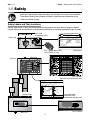
SV Series
Insert Manual
For complete installation instructions, see the Tube Heater General Manual
that accompanies this Series Insert Manual.
The SV Series Infrared Tube Heater is a negative pressure, single-stage radiant heater system. This insert
manual is a supplement to the Tube Heater General Manual and provides specific information related to
the SV Series model. All persons involved with the installation, operation and maintenance of the heater
system must read and understand the information in this insert manual and the accompanying Tube
Heater General Manual.
!
WARNING
Improper installation, adjustment, alteration, service or maintenance can cause
property damage, injury or death. Read the installation, operation and maintenance
instructions thoroughly before installing or servicing this equipment.
This heater must be installed and serviced by trained gas installation and service
personnel only. Failure to comply could result in personal injury, asphyxiation, death,
fire or property damage.
In locations used for the storage of combustible materials, signs must be posted to
specify the maximum permissible stacking height to maintain the required clearances
from the heater to the combustibles. Signs must either be posted adjacent to the
heater thermostats or in the absence of such thermostats, in a conspicuous location.
Not for residential use! Do not use this heater in the home, sleeping quarters,
attached garages, etc. Installation of a commercial tube heater system in residential
indoor spaces may result in property damage, serious injury, asphyxiation or death.
For Your Safety
If you smell gas:
• Do not try to light any appliance. • Immediately call your gas supplier from a neighbor’s phone.
• Do not touch any electrical switch.
• Follow the gas supplier’s instructions.
• Do not use any phone in your building. • If you cannot reach your gas supplier, call the fire department.
Keep these instructions for future reference.
LIOSVa-Rev. 18111
Print: 1M-9/12_r1-2/13 (CDS)
Replaces: LIOSVa-1M-1/11 (DRP)
SV Series
Contents
1.0 Safety . . . . . . . . . . . . . . . . . . . . . . . . . . . . . . . . . . . . . . . . . . . . . . . . . . . . . . . . . . . . . . . . . . 3
Safety Labels and Locations . . . . . . . . . . . . . . . . . . . . . . . . . . . . . . . . . . . . . . . . . . . 3
Clearance to Combustibles . . . . . . . . . . . . . . . . . . . . . . . . . . . . . . . . . . . . . . . . . . . . 4
2.0 Installation . . . . . . . . . . . . . . . . . . . . . . . . . . . . . . . . . . . . . . . . . . . . . . . . . . . . . . . . . . . . . . 6
Gas Requirements . . . . . . . . . . . . . . . . . . . . . . . . . . . . . . . . . . . . . . . . . . . . . . . . . . . 6
Electrical Requirements . . . . . . . . . . . . . . . . . . . . . . . . . . . . . . . . . . . . . . . . . . . . . . . 6
Thermostat . . . . . . . . . . . . . . . . . . . . . . . . . . . . . . . . . . . . . . . . . . . . . . . . . . . . . . . . . 7
Wiring . . . . . . . . . . . . . . . . . . . . . . . . . . . . . . . . . . . . . . . . . . . . . . . . . . . . . . . . . . . . . 7
Specifications . . . . . . . . . . . . . . . . . . . . . . . . . . . . . . . . . . . . . . . . . . . . . . . . . . . . . . . 10
Tube Installation Sequence . . . . . . . . . . . . . . . . . . . . . . . . . . . . . . . . . . . . . . . . . . . . 11
Exhauster Mounting Details . . . . . . . . . . . . . . . . . . . . . . . . . . . . . . . . . . . . . . . . . . . 12
3.0 Operation . . . . . . . . . . . . . . . . . . . . . . . . . . . . . . . . . . . . . . . . . . . . . . . . . . . . . . . . . . . . . . . 13
Sequence of Operation . . . . . . . . . . . . . . . . . . . . . . . . . . . . . . . . . . . . . . . . . . . . . . . 13
Operational Indicator Lights . . . . . . . . . . . . . . . . . . . . . . . . . . . . . . . . . . . . . . . . . . . . 13
4.0 Troubleshooting Guide . . . . . . . . . . . . . . . . . . . . . . . . . . . . . . . . . . . . . . . . . . . . . . . . . . . 14
5.0Parts . . . . . . . . . . . . . . . . . . . . . . . . . . . . . . . . . . . . . . . . . . . . . . . . . . . . . . . . . . . . . . . . . . 18
Heater Components & Parts List . . . . . . . . . . . . . . . . . . . . . . . . . . . . . . . . . . . . . . . . 18
Kit Contents Check List . . . . . . . . . . . . . . . . . . . . . . . . . . . . . . . . . . . . . . . . . . . . . . 20
Approvals . . . . . . . . . . . . . . . . . . . . . . . . . . . . . . . . . . . . . . . . . . . . . . . . . . . . . . . . . 20
Limited Warranty . . . . . . . . . . . . . . . . . . . . . . . . . . . . . . . . . . . . . . . . . . . . . . . . . . . 20
NOTE: See page 10 for a list of available models and specifications.
2
SV Series
1.0 Safety • Safety Labels and Locations
1.0 Safety
Read and understand all safety information and warnings in this insert manual and the
Tube Heater General Manual before installation, operation and maintenance of the
radiant tube heater system.
Safety Labels and Their Locations
Product safety signs or labels should be replaced by the product user when they no longer are legible.
Contact either your local distributor or the product manufacturer for obtaining replacement signs or labels.
SAMPLE
Air Metering Orifice
DO NOT REMOVE
TP-114
TP-3014
1 - 1/2"
F/N: LLAC
Air Metering Orifice
®
RE-VERBER-RAY INFRA-RED RADIANT TUBE HEATER
FOR INDOOR (Non-Residential) INSTALLATION ONLY.
Class IIIA Permanent Label
Back Panel
MODEL NO.
INPUT BTU/H
SV- 40 - 125N
Volts AC:
SV
FOR USE WITH
125,000
Manifold Pressure:
24V - 60Hz
3.5 in.
AMPS - Starting:
W.C.P.
M
SA
P
Maximum Inlet Pressure:
3.0
14 in.
AMPS - Running:
W.C.P.
LE
Minimum Inlet Pressure:
2.0
5.5 in.
Combustion Chamber:
Natural Gas
Heater Type
C1
Minimum Mounting Angle:
0
DEGREES
Maximum Mounting Angle:
W.C.P.
45 DEGREES
4” Black Coated Aluminized
DESIGN COMPLIES WITH:
ANSI Z83.20b-2004-GAS FIRED LOW INTENSITY INFRA-RED HTR.
DETROIT RADIANT PRODUCTS COMPANY
21400 HOOVER ROAD - WARREN, MI
(586) 756-0950
www.drp-co.com
F/N: LLTB018 (Natural Gas)
F/N: LLTB019 (LP Gas)
Serial No.: 0807XXXXXXXXXX 0001
Rating Plate
Top Panel
F/N: LLTCL001
Clearance to Combustibles Label.
SV-40-125N
Production Code:
Version:
Serial No.: 0804XXXXXXXXXX 0001
Stock:None
Add-On: N/A
SV-125
Data on this label is for the model shown on this label. If your heater has been converted,
this information is not accurate. Please contact the factory for assistance.
BURNER COMPONENTS: (Specify TP-#’s)
Bottom Panel
Gas Valve:
Circuit Board:
Wire Harness:
N.O. Switch:
N.O. VL Orifice:
N.C. Switch:
N.C. VL Orifice:
Diff Switch:
Diff VL Orifice:
Igniter:
Burner:
16” Tube:
Ind. Lights:
HEATER
TYPE:
C1
36G54-224
Triton - 2465H
None
None
N/A
None
None
IS22016051F5169
Black(+ / -)
24V Norton
High
4” 24 Mini
Yellow - 24V
1240A
1251
None
N/A
N/A
SA
Orifice Type:
Gas: TP-204#
Air: TP-114#
264E
M
E
PL
1250
201B
1280
828
Diag. Light:
Term. Block:
Transformer:
Fan:
Alt. Fan:
Alt. Fan Usage:
Relay:
Filter:
24 Volt In:
120 Volt In:
Gas In:
Extra VL Orifice:
None
10 - Spade
None
PB - (7-10)
None
Pack 1 p/ burner
None
None
2T - plug
trans Box
7/8” FC Flare
Yellow
C1
C2
C3
Internal Use Only:
10
2 1/4”
10
2 1/4”
9
2 1/4”
Electric: LLWT020
Tag:
None
329
826
1215
N/A
N/A
N/A
832
1266
83
Special 1: Pump ID
Special 2: 24V - ID
For parts replacement information, contact factory at 586-756-0950 or visit www.drp-co.com/parts.
Burner Control Box
Component Label
(located under the top panel)
F/N: LLLOGO1
3
SV Series
1.0 Safety • Safety Labels and Locations • Clearance to Combustibles
V
PS
VALVE
PRESSURE
SWITCH
F/N: LLV3EP6
Left Panel
Combustion
Chamber
16” Burner Tube
Radiant
Tube
SERVICE ACCESS PANEL
IGNITER & FLAME SENSE COMPARTMENT
1. Turn off gas & electricity.
2. Remove cover by lifting top
cover upward and outward.
CAUTION: HOT SURFACE.
KEEP COVER IN PLACE. REMOVE FOR SERVICE ONLY.
Right Panel
(Valve Compartment)
!
SERVICE ACCESS PANEL
IGNITER & FLAME SENSE COMPARTMENT
INSTALLER
AVOID EQUIPMENT FAILURE
1. Turn off gas & electricity.
2. Remove cover by lifting top
cover upward and outward.
THIS 10 FT. TUBE IS THE
COMBUSTION CHAMBER.
CAUTION: HOT SURFACE.
The combustion chamber utilizes either 409
stainless, titanium alloy or aluminized steel depending on the model number of your heater.
KEEP COVER IN PLACE. REMOVE FOR SERVICE ONLY.
F/N: LLTB026
THIS TUBE MUST BE THE FIRST TUBE
FOLLOWING THE BURNER CONTROL BOX.
Rotate the tube’s welded seam to bottom.
Consult the manual(s) for further details.
F/N: LL01 - Clearance Safety Tag
(Affix adjacent to heater’s thermostat).
F/N: LLTB004 (orange)
Applicable on 150-200 MBH models only
Power Box
Front View
V
F/N: LLTB032
p
Out ut
V
24
24
Exhauster Pump
Assembly
Side View
ox
lB
CO
M
LLTB033
tr
To
Burner Con
Clearance to Combustibles
!
o
F/N: LLTB033
WARNING
Placement of explosive objects, flammable objects, liquids and vapors close to
the heater may result in explosion, fire, property damage, serious injury or death.
Do not store or use explosive objects, liquids or vapor in the vicinity of the heater.
Clearance to combustibles is defined as the minimum distance that must be maintained between the tube
surface, or reflector, and any combustible items (see Figure 1.1). It also pertains to the distance that must
be maintained from moving objects around the tube heater. Refer to Chart 1.1 to determine the required
distances for your model.
4
SV Series
1.0 Safety • Clearance to Combustibles
Chart 1.1 • Clearance to Combustibles in Inches (see Figure 1.1 for Mounting Angles)
Model Number
SV (20, 30, 40) - 50, 60 [N, P]
with 1 side shield
with 2 side shields
20 ft. from burner
SV (20, 30, 40) - 75 [N, P]
with 1 side shield
with 2 side shields
20 ft. from burner
SV (30, 40, 50) - 100 [N, P]
with 1 side shield
with 2 side shields
20 ft. from burner
SV (30, 40, 50) - 125 [N, P]
with 1 side shield
with 2 side shields
20 ft. from burner
SV (40, 50, 60) - 150 [N, P]
with 1 side shield
with 2 side shields
20 ft. from burner
SV (40, 50, 60, 70) - 175 [N, P]
with 1 side shield
with 2 side shields
20 ft. from burner
SV (50, 60, 70, 80) - 200 [N, P]
with 1 side shield
with 2 side shields
20 ft. from burner
Side
Mounting
Angle*
Front
Behind
Top
Below
0°
45°
0°
0°
0°
0°
45°
0°
0°
0°
0°
45°
0°
0°
0°
0°
45°
0°
0°
0°
0°
45°
0°
0°
0°
0°
45°
0°
0°
0°
0°
45°
0°
0°
0°
9
39
29
9
7
9
39
29
9
7
14
39
29
16
7
20
58
42
20
7
24
58
42
23
11
34
63
50
30
11
41
63
54
30
11
9
8
8
9
7
9
8
8
9
7
14
8
8
16
7
20
8
8
20
7
24
8
8
23
11
34
8
8
30
11
41
8
8
30
11
6
10
6
6
6
6
10
6
6
6
6
10
6
6
6
6
10
6
6
6
6
10
6
6
6
6
10
6
6
6
6
10
6
6
6
47
47
47
47
30
60
60
60
60
30
66
66
66
66
30
76
76
76
76
30
81
81
81
81
44
92
92
92
92
44
94
94
94
94
44
*Heaters mounted on an angle between 0° to 45° must maintain clearances posted for 0° or 45°; whichever is greater.
The stated clearance to combustibles represents a surface temperature of 90°F (32°C) above room
temperature. Building materials with a low heat tolerance (such as plastics, vinyl siding, canvas,
tri-ply, etc.) may be subject to degradation at lower temperatures. It is the installer’s responsibility to
assure that adjacent materials are protected from degradation.
Figure 1.1 • Mounting Angles
0° Mounting Angle
45° Mounting Angle
Top
Top
Side
Side
Below
0° Mounting Angle
with 1 Side Shield
(P/N: SSE)
Top
Behind
Front
Below
Front
5
Behind
Below
0° Mounting Angle
with 2 Side Shields
(P/N: SSE)
Top
Side
Side
Below
SV Series
2.0 Installation • Gas Requirements • Electrical Requirements
2.0 Installation
!
WARNING
Not for residential use! Improper installation, adjustment, alteration, service or
maintenance can cause property damage, serious injury or death.
Read and understand, the installation, operating and maintenance instructions thoroughly
before installing or servicing this equipment. Only trained, qualified gas installation and
service personnel may install or service this equipment.
Instructions for the following are detailed in the Tube Heater General Manual:
• Design considerations
• Hanger suspension and placement
• Tube layout and assembly
• Burner control box suspension
• Reflectors (and accessories)
• Venting and combustion air intake
• Gas requirements
• Baffle assembly
Note: Electronic versions of all manuals are available at www.detroitradiant.com
Gas Requirements
Type of Gas
Required Manifold
Pressure
Minimum Inlet
Pressure
Maximum Inlet
Pressure
Natural
3.5 Inches W.C.
5.0 Inches W.C.
14.0 Inches W.C.
Liquefied Petroleum
10.0 Inches W.C.
11.0 inches W.C.
14.0 Inches W.C.
NOTE: Check manifold pressure at the tap on the gas valve. Small variations in manifold pressure
(actual vs. published) may exist due to changing atmospheric conditions. Readings will be above
atmospheric pressure.
IMPORTANT: Consult the Tube Heater General Manual for gas connection requirements.
Electrical Requirements
!
WARNING
Electric Shock
Field wiring to the tube heater must be connected and grounded in accordance with national,
state, provincial, local codes and to the guidelines in the Tube Heater General Manual and
Series Insert Manual. In the United States refer to the most current revisions to the ANSI/NFPA
70 Standard and in Canada refer to the most current revisions to the CSA C22.1 Part I Standard.
Power to the exhauster assembly is supplied via a 120VAC-60Hz. connection and controlled via a
thermostat or switch. The burner control box is powered by 24VAC via the terminal plug connection from
the exhauster power box assembly. See Figures 2.1-2.2.
• 120 Volt - 60 Hz GRD, 3-wire.
• Starting current 3.0 amps
• Running current 2.0 amps
6
SV Series
2.0 Installation • Thermostat • Wiring
The use of 14 ga. minimum multi strand wire (field supplied) is required to connect the exhauster
assembly to the burner control box. A round terminal plug accepts two (2) 1/4” insulated female spade
terminals (field supplied).
IMPORTANT: The wire (field supplied) connecting the exhauster power box assembly to the burner
control box must be mounted a minimum of 18 inches from the top of the reflector and outside of any
other clearance requirements. The span of wire must allow for several inches of heater expansion.
Thermostat
SV Series heaters require a 120VAC thermostat to operate. NOTE: Different thermostats operate
according to their particular features. Refer to thermostat specifications for details.
NOTE: The wire (field supplied) is not where the thermostat is tied into. The thermostat switches the
120VAC supply voltage. Refer to field wiring diagrams (Figures 2.1A & 2.1B).
Wiring
NOTE: If any of the original wire as supplied with the appliance must be replaced, it must be replaced
with wiring material having a temperature rating of at least 105° C.
Figure 2.1 • Field Wiring Diagrams
A. Line Voltage Thermostat Wiring - Single thermostat (20 amp), up to six heaters.
L1
Neutral
Ground
120VAC-60Hz.
Supply
Low voltage wire (14 ga. multistrand required)
must be installed a minimum of 18 in. from the reflector
and outside of the clearance to combustibles zone.
T
1/4” female spade
terminals required
(as supplied).
SV Series
Burner Box
Power Box
1/4” female spade
terminals required
(as supplied).
W
G
BK
Up to five
additional
heaters
7
SV Series
2.0 Installation • Wiring
Figure 2.1 • Field Wiring Diagrams
B. Low Voltage Thermostat Wiring (with optional R8285B transformer relay) - Up to Five Heaters per branch.
Low Voltage Thermostat
C
W R
Common required for thermostats
that require constant power.
N
To heater branch #1
120VAC
W
L1
To heater branch #2
(Up to five heaters per branch)
14 ga. multistrand
low voltage wire
(as supplied)
V
W
BK
POLE
#1
POLE
#2
W
G
R8285B Transformer Relay (optional)
Required when wiring line voltage
heaters to any low voltage thermostat.
Y
R
Coil
C
W
B
N
120V
L1
R/Y
R
Low voltage wire (14 ga. multistrand
required) must be installed a
minimum of 18 inches from the
reflector and outside of the
clearance to combustibles zone.
1/4” female
spade terminals
(as supplied).
SV Series
Burner Box
Power Box
Assembly
1/4” female spade
terminals (as supplied).
W
BK
Up to four
additional heaters
8
SV Series
2.0 Installation • Wiring
Figure 2.2 • Internal Wiring Diagrams
A. TP-1251 Ladder Diagram
L1 120V
N
Blower
W
BK
Exhauster
Power Box
Assembly
120V
24V
Fuse
24V Indicator Light
Switch
Light
Y
Y
LED
ON = Control Fault
2 Flashes = Flame, No Call for Heat
3 Flashes = Ignition Lockout
W
MV1
S1 L1 L2 S2
Burner
Control
Box
Flame
Rod
GND
Ignition Module
BK
G
BK
Valve
Light
BK
W
W
Igniter
Gas Valve
Field Supplied Wiring
B. TP-1251 Block Diagram
Factory Wiring
Burner Control Box
Igniter
LED
L1
Pressure
Switch
Blower
Motor
120V
N
ON = Control Fault
2 Flashes = Flame, No Call for Heat
3 Flashes = Ignition Lockout
Ignition Module
S1 L1 L2 S2
W
MV1
GND
Exhauster Power
Box Assembly
Flame
Rod
24V
120V
24V
Fuse
Terminal
Block
Indicator
Light
Gas Valve
Indicator Lights
24V
24V
Field Supplied Wiring
Factory Wiring
9
Burner
SV Series
2.0 Installation • Specifications
Specifications
Model
Number
Gas Type
(select one)
BTU/h
Straight Length
U-Tube Length
Standard
Weight (lbs.)
Recommended
Mounting Height
Combustion Chamber
Radiant Emitter
Tube(s) (Black Coated)
Radiant Surface Area
(sq. ft.)
36” Baffle Sections
Maximum Vent
Length (ft.)
Chart 2.1 • Specifications
SV-20-50
N or LP
50,000
22’-7”
13’-0”
140
9’ to 14’
Alum
Alum
20.2
5
25
SV-20-60
N or LP
60,000
22’-7”
13’-0”
140
10’ to 15’
Alum
Alum
20.2
5
25
SV-20-75
N or LP
75,000
22’-7”
13’-0”
140
10’ to 15’
Alum
Alum
20.2
5
30
SV-30-50
N or LP
50,000
32’-3”
**17’-8”
180
10’ to 15’
Alum
Alum
30.4
4
20
SV-30-60
N or LP
60,000
32’-3”
**17’-8”
180
11’ to 18’
Alum
Alum
30.4
4
20
SV-30-75
N or LP
75,000
32’-3”
**17’-8”
180
12’ to 20’
Alum
Alum
30.4
4
25
SV-30-100
N or LP
100,000
32’-3”
**17’-8”
180
13’ to 23’
Alum
Alum
30.4
3
30
SV-30-125
N or LP
125,000
32’-3”
**17’-8”
180
14’ to 25’
Alum
Alum
30.4
5
35
SV-40-50
N or LP
50,000
41’-11”
22’-8”
210
11’ to 18’
Alum
Alum
40.5
3
20
SV-40-60
N or LP
60,000
41’-11”
22’-8”
210
11’ to 18’
Alum
Alum
40.5
3
20
SV-40-75
N or LP
75,000
41’-11”
22’-8”
210
12’ to 20’
Alum
Alum
40.5
3
25
SV-40-100
N or LP
100,000
41’-11”
22’-8”
210
13’ to 23’
Alum
Alum
40.5
2
25
SV-40-125
N or LP
125,000
41’-11”
22’-8”
210
14’ to 25’
Alum
Alum
40.5
4
30
SV-40-150
N or LP
150,000
41’-11”
22’-8”
210
15’ to 27’
Titan
Alum
40.5
4
35
SV-40-175
N or LP
175,000
41’-11”
22’-8”
210
16’ to 30’
Titan
Alum
40.5
4
35
SV-50-100
N or LP
100,000
51’-7”
**27’-4”
255
15’ to 27’
Alum
Alum
50.6
1
25
SV-50-125
N or LP
125,000
51’-7”
**27’-4”
255
15’ to 27’
Alum
Alum
50.6
3
30
SV-50-150
N or LP
150,000
51’-7”
**27’-4”
255
16’ to 30’
Titan
Alum
50.6
3
30
SV-50-175
N or LP
* 175,000
51’-7”
**27’-4”
255
17’ to 35’
Titan
Alum
50.6
3
35
SV-50-200
N or LP
* 200,000
51’-7”
**27’-4”
255
18’ to 40’
Titan
Alum
50.6
4
35
SV-60-150
N or LP
150,000
61’-3”
32’-4”
285
17’ to 35’
Titan
Alum
60.7
2
25
SV-60-175
N or LP
* 175,000
61’-3”
32’-4”
285
17’ to 35’
Titan
Alum
60.7
2
30
SV-60-200
N or LP
* 200,000
61’-3”
32’-4”
285
18’ to 40’
Titan
Alum
60.7
3
30
SV-70-175
N or LP
* 175,000
70’-11”
**37’-0”
320
19’ to 42’
Titan
Alum
70.9
1
25
SV-70-200
N or LP
* 200,000
70’-11”
**37’-0”
320
19’ to 42’
Titan
Alum
70.9
2
30
SV-80-200
N or LP
* 200,000
80’-7”
42’-0”
350
20’ to 45’
Titan
Alum
80.1
1
25
See Figure 2.6 for exhauster assembly dimensions.
* Model requires stainless steel tube clamp (P/N: TP-220) to be located at the seam between the first and second
10 ft. tube sections downstream of the burner control box.
** Model requires 5EA-SUB accessory package when installing in a ‘U’ configuration (P/N: TF1B).
Titan = Black coated titanium stabilized aluminized steel.
Alum = Black coated aluminized treated steel.
10
SV Series
2.0 Installation • Tube Installation Sequence • Heater Length
Tube Installation Sequence
Figure 2.4 • Tube Installation Sequence
Important! The combustion chamber & radiant tube sections must be installed in the following order.
20 Foot
30 Foot
40 Foot
50 Foot
Stainless steel clamp location on 175 - 200 MBH models only (P/N: TP-220).
60 Foot
Stainless steel clamp location on 175 - 200 MBH models only (P/N: TP-220).
70 Foot
Stainless steel clamp location on 175 - 200 MBH models only (P/N: TP-220).
80 Foot
Stainless steel clamp location on 175 - 200 MBH models only (P/N: TP-220).
Key
Standard Tube Clamp
Burner Control Box with
16” Burner Tube
Stainless Steel Tube
Clamp (P/N: TP-220)
Combustion Chamber
175-200 MBH models only - Located
between 1st and 2nd 10 ft. tube sections.
Coated Aluminized
Radiant Emitter Tube
Exhauster Pump Assembly
Baffle Location
Security Chain Location (P/N: THCS)
Note: Refer to the Tube Heater General Manual, Chart 3.6 (page 23) for secured reflector joints.
11
SV Series
2.0 SV Series Installation • Exhauster Mounting Details
Exhauster Mounting Details
When installing this heater in a U-shaped configuration, the exhauster assembly and the burner control box must
not interfere with each other. When looking at the U-shaped configuration from behind, the burner control box is on
the left and the exhauster assembly is on the right. See Figure 2.5.
Figure 2.5 • Exhauster Assembly Mounting Details - U-Shaped Configuration
16”
Security Chain
35”
Figure 2.6 • Exhauster Assembly Dimensions
10”
16”
18.5”
SIDE VIEW
END VIEW
12
SV Series
3.0 Operation • Sequence of Operation • Operational Indicator Lights
3.0 Operation
!
WARNING
This heater must be installed and serviced by trained gas installation and service
personnel only.
Do not bypass any safety features or the heater’s built in safety mechanisms will
be compromised.
NOTE: Reference the Tube Heater General Manual (F/N: LIOGTa) for installation requirements.
Sequence of Operation
Starting Circuit: Upon a call for heat, the exhauster fan energizes creating a negative air pressure
allowing the differential pressure switch to close. A low voltage circuit is completed from the
secondary side of the transformer to the ignition module. After a five (5) second delay, the igniter is
powered. After seven (7) seconds, gas valve opens initiating the ignition trial. If flame is not sensed
after 15 seconds, the heater will attempt to re-ignite for a total of three (3) trials for ignition before
entering lockout mode.
Running Circuit: After ignition, the flame rod monitors burner flame. If sense of flame is lost, the control
closes the gas valve within one second and a new trial sequence (identical to the starting sequence)
is initiated. If flame sense is not established within 15 seconds, the heater will attempt two (2)
additional ignition sequences before entering lockout mode. The control can be reset by briefly
interrupting the power source.
Operational Indicator Lights
Figure 3.1 • Operational Indicator Lights
Exhauster End View
Burner Control Box
Left Panel View
V
PS
VALVE
PRESSURE
SWITCH
Light 1
Indicates Power
to Valve
Light 2
Indicates Pressure
Switch Closes
Operational Indicator Lights
Power Box Light
Indicates 24VAC
13
SV Series
4.0 Troubleshooting Guide
4.0 Troubleshooting Guide
Turn up thermostat
Does the exhauster
fan turn on?
Is the power at the
exhauster 120V?
No
Yes
Is the exhauster
obstructed?
No
No
Yes
Yes
Find the source of the
electrical problem.
Does the pressure
switch light energize?
Remove obstruction
and lubricate fan.
Is the light burnt out?
If so, replace.
No
Is the inlet or the outlet of
the unit obstructed (i.e.,
ice, birds nest, dirt, etc.)?
No
Replace igniter.
No
Yes
Yes
Yes
Does the igniter warm
up and glow red?
Is 24V going from the
exhauster power box
assembly to the burner
control box?
No
Yes
Remove obstruction.
Is the igniter
physically damaged?
No
No
Yes
Replace
transformer.
Does the valve
light energize?
No
Does the burner
ignite at all?
No
Yes
Yes
Replace faulty light.
No
Yes
No
Does valve open?
Yes
Check voltage on the
secondary side of the
transformer. Is it 24V?
Repair faulty wiring
between the
exhauster power box
assembly and the
burner control box.
No
Continued on page 16.
Replace faulty circuit board
and/or wiring harness.
Test for 24V at valve during
opening period (usually 7
seconds after power to heater).
Is there 24V to the valve?
14
Yes
Confirm that gas pressure
is within minimum and
maximum inputs as
indicated on the burner
rating plate. Is it ok?
No
Yes
SV Series
4.0 Troubleshooting Guide
Bypassing any switch is intended for testing purposes only. Do not leave switch bypassed
during normal operation or the heater’s built-in safety mechanisms will be compromised.
NOTICE
Key
Start
Question
The fan is faulty
and must be
replaced.
Process
Question
No
Corrective
Action
Replace faulty light.
Repair.
No
Check for loose wiring
or resistance in hose
connection to pressure
switch. Are they ok?
Check voltage at igniter during
ignition sequence (usually 7
seconds after power to the
burner control box). Is it 24V?
No
Replace circuit board.
Yes
The Heater is equipped with a safety pressure
switch. This differential switch, located in the
ignition controls compartment, is a normally
open pressure switch. Temporarily place
jumpers across the terminals of the switch (Be
sure to reinstall the burner control box cover).
Does the light energize?
Yes
Yes
Is resistance through
the igniter 1-6 Ω ?
No
Replace
igniter.
Yes
Replace
faulty wiring.
Replace the differential switch after verifying the following:
• Baffle(s) is/are in the radiant tube(s) farthest from the burner.
• The heater, fan blower, squirrel cage, intake and exhaust are free from
dirt and obstructions.
• The 4” air intake pipe does not exceed 20 feet and/or 2 elbows.
• There is not a negative pressure experienced at the area of air intake
(i.e., attic space, high winds, very tight building).
Correct problem.
If any of the above are occurring, please address the problem.
Replace gas valve.
15
SV Series
4.0 Troubleshooting Guide
Continued from page 14
Does the
burner ignite?
No
Is the gas supply
to the heater in
the ON position?
Yes
Is the proper gauge wire used between
the exhauster power box assembly and
the burner control box?
No
No
Yes
Use 14 gauge multistrand wire.
Turn on.
Does the burner
stay on?
No
Does the burner stay on
for approx. 15 seconds
and then shut off?
Yes
No
Does the burner come
on and turn off
immediately (1 or 2
seconds)?
Yes
Does the heater
stay ON until the
call for heat ends?
No
Yes
Yes
Yes
Check to make sure gas pressure
is within minimum and maximum
inputs, as indicated on the burner
rating plate. Is gas pressure OK?
The heater can shut down due to:
•Improper grounding.
•High winds.
•Taking combustion air from the attic.
•Dirty environment.
•Improperly positioned baffles.
•Fluctuating gas pressure.
Troubleshooting ends
16
No
Correct problem.
Yes
Pressure
switch may
be faulty or
there is a
restriction in
the exhaust.
SV Series
4.0 Troubleshooting Guide
Use larger gauge wire.
Correct pressures.
No
No
Check voltage at burner
control box during igniter
warm up. Is it at least 24V?
Is the heater properly
grounded? Is the heater’s
polarity correct?
Yes
Check to make sure gas pressure is within
minimum and maximum inputs, as indicated on
burner rating plate. Is gas pressure OK?
Yes
Confirm manifold pressure is
correct and/or gas orifice is not
plugged and is the correct size.
Yes
No
Purge gas line.
Yes
No
Correct problem.
With microampmeter, check
amperage at flame rod. Is it
greater than .7 microamps?
Were the gas
lines purged of
air?
Yes
No
Sensing rod is faulty or flame
is weak. Check to make sure
heater is operating at proper
gas pressure as indicated on
burner rating plate and then, if
needed, replace sensing rod.
17
Check to make sure flame
sensor wire is OK. If so,
then replace circuit board.
SV Series
5.0 Parts • Heater Components and Parts List
5.0 Parts
Figure 5.1 • Burner Assembly
Components
219
APS
207
97
17
1202
1251
828
329
31B
804, 1204
114
84
21B
301
70
832
1
14
15
16
1283
218
1280
5
13
212
76
33B
83
217
1250
9
200A, 201B
31B 13
223
204
1240A, 1241A
208A
321
221
222, 222A
214
11
10
12
303
85
Chart 5.1 • Parts List
Part No.
Description
Part No.
Description
TP-1
Control Box Cover
TP-65I
36 in. Interlocking Turbulator Baffle
TP-5
TP-9
TP-10
TP-11
TP-12
TP-13
TP-14
TP-15
TP-16
TP-17
TP-19B
TP-20C
TP-20D*
TP-21B
TP-26A
TP-26B
TP-26D*
TP-26E*
TP-31B
TP-33B
Flange Gasket
Conduit Coupling
Conduit 4 in. x 1/2 in.
Hot Surface Igniter Box
Hot Surface Igniter Box Cover
8 x 1/2” Self-Drilling Screw (Qty. 2)
Sight Glass Gasket
Sight Glass
Sight Glass Washer
Sight Glass Kit
4 in. Wire Hanger with Tension Spring
120 in. Aluminum Reflector
120 in. Stainless Steel Reflector
4 in. Standard Tube Clamp
10 ft. Aluminized Radiant / Combustion Tube
10 ft. Titanium Coated Combustion Tube
10 ft. 304 Stainless Steel Radiant Tube
10 ft. 409 Stainless Steel Combustion Tube
Control Box Mounting Bracket (Qty. 2)
1/2 in. Shut-Off Ball Valve / Inlet Tap
TP-70
TP-76
TP-82
TP-83
TP-84
TP-85
TP-97
TP-105
TP-106
TP-113
TP-114
TP-200A
TP-201B
TP-204
TP-207
TP-208A
TP-212
TP-214
TP-217
TP-218
Control Box Cover Gasket (per foot**)
Rubber Grommet
Reflector Center Support (RCS)
24 in. Stainless Steel Flexible Gas Connector
1/2 in. Female / Male Flare Fitting
1/2 in. Male / Male Flare Fitting
1/4 in. x 1/4 in. Brass Barb Fitting (Qty. 2)
Aluminum Reflector End Cap
Reflector End Cap Clips (Qty. 8)
Reflector Tension Spring
Plastic Air Orifice w/ Screen (Consult factory)
Low BTU Burner (Blue) - consult factory
Mid BTU Burner (Tan) - consult factory
Gas Orifice (consult factory)
Pressure Switch Mounting Bracket
Gas Valve Mounting Bracket
1/2 in. x 3 in. Pipe Nipple
Glo-Bar Wiring Harness
Pressure Switch Barb Fitting
Differential Switch Vinyl Sensing Tube (exhaust)
* Optional upgrade or add-on item.
**6 feet total required to cover outer edges of the burner control box.
18
SV Series
5.0 Parts • Heater Components and Parts List
Figure 5.2 • Tube & Reflector Components
THCS
1215
1243
106
82
20C/D*
1526A
1266
r
tte
mi
E
nt
dia
a
R
113
579
105
19B
(s
be
Tu
1289
)
1232
1220
533
828
1297
1229
26A/D*
s)
er(
b
am
Ch
n
o
sti
bu
m
Co
65I
1255
21B, 220
26A/B/E*
Part No.
Description
Part No.
Description
TP-219
Differential Vinyl Sensing Tube (burner)
TP-1250
24V Mini Igniter
TP-220
Stainless Steel Tube Clamp (175 & 200 MBH)
TP-1251
Self Diagnostic Ignition Module
TP-221
TP-222
TP-222A
TP-223
TP-301
TP-303
TP-321
TP-329
TP-579
TP-804
TP-828
TP-832
TP-1202
TP-1204
TP-1215
TP-1240A
TP-1241A
TP-1243
Mini Igniter Gasket
Flame Rod
Flame Rod Wire
Gas Manifold
Center Panel
End Panel, Right
Ignition Plate Gasket
Terminal Block
4 in. Wire Hanger w/o Tension Spring
Burner Control Box Outer Shell (50-175 MBH)
Yellow Operational Ind. Light (Qty. 2)
Thermostat Terminal Strip
End Panel, Left
Burner Control Box Outer Shell (200 MBH)
Exhauster Pump
24V Gas Valve - Natural Gas Assembly
24V Gas Valve - LP Gas Assembly
Blower Restrictor Plate - Specify Model
TP-1255
TP-1266
Full Exhauster Assembly (TP-1215, TP-1266, TP-1243)
Power Box Assembly (individual parts below)
TP-533
120V Conduit Connector
TP-828
Power Box 24V Yellow Indicator Light
TP-1220
Power Box Mounting Bracket
TP-1229
Fuse Holder
TP-1232
Terminal Plug
TP-1289
Exhauster Mounting Tube
TP-1297
Fuse
TP-1526A
TP-1280
TP-1283
TP-APS
Differential Pressure Switch, 50 to 75 MBH
TP-264E
Differential Pressure Switch, 100 to 125 MBH
TP-264F
THCS
19
16” Burner Tube with Flange
Mini Igniter Plate
Atmospheric Pressure Switch (see below)
TP-264B
TP-1264A
* Optional upgrade or add-on item.
75VA Transformer with Foot Mounts
Differential Pressure Switch, 150 to 175 MBH
Differential Pressure Switch, 200 MBH
Exhauster Assembly Security Chain
SV Series
5.0 Parts • Kit Contents Check List • Approvals • Limited Warranty
Kit Contents Check List
Chart 5.2 • Kit Contents for SV Series - Reference the length column for your model.
SV Series Kit Contents
TP-19B 4” Hanger with
Reflector Tension Spring
TP-82 4” Reflector
Center Support (RCS)
TP-106
TP-25
Reflector
1/4” Female
End Cap Clips Spade Terminal
TP-33B 1/2” Shut-Off
Ball Valve / Inlet Tap
THCS 60 in. Security Chain
TP-83 24” Stainless Steel
Flexible Gas Connector
Part No.
Description
TP-19B
TP-21B 4” Tube Clamp
TP-105
Reflector End Cap
F/N: LIOGTa & LIOSVa
Tube Heater
General Manual and
SV Series Insert Manual
Tube Heater
General Manual
HL2 Serie
s
Insert M
anual
20 ft.
30 ft.
40 ft.
50 ft.
60 ft.
70 ft.
80 ft.
4” Hanger w/ Tension Spring
3
4
5
6
7
8
9
TP-21B
4” Tube Clamp
3
4
5
6*
7*
8*
9*
TP-25
1/4” Female Spade Terminal
4
4
4
4
4
4
4
TP-33B
1/2” Shut-Off Valve & Inlet Tap
1
1
1
1
1
1
1
TP-82
4” Reflector Center Support
2
3
4
5
6
7
8
TP-83
24” S.S. Flexible Gas Connector
1
1
1
1
1
1
1
TP-105
Reflector End Cap
2
2
2
2
2
2
2
TP-106
Reflector End Cap Clips
8
8
8
8
8
8
8
THCS
60 in. Security Chain
1
1
1
1
1
1
1
LIOGTa
General Tube Heater Manual
1
1
1
1
1
1
1
LIOSVa
SV Series Insert Manual
1
1
1
1
1
1
1
Filled By:
* One 4” stainless steel tube clamp (P/N: TP-220) is provided for each 175,000 - 200,000 BTU model. Place as
shown on page 11.
Approvals
Limited Warranty
• CSA
• Indoor approval.
• Commercial approval.
•
•
•
•
Printed in U. S. A.
1 year - Burner box components.
3 years - Combustion and radiant tubes.
5 years - Stainless steel burner.
See page 36 of the General Tube Heater Manual for terms and conditions.
© 2013 Detroit Radiant Products Co.
21400 Hoover Road • Warren, MI 48089
Phone: (586) 756-0950 Fax: (586) 756-2626
www.detroitradiant.com • [email protected]