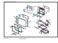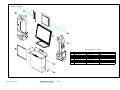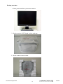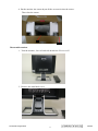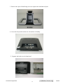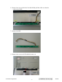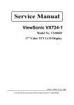
1
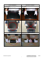
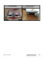
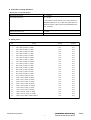
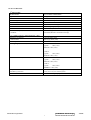
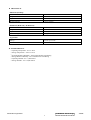
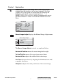
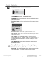
Service Manual ViewSonic VX912-1 Model No. VS10162 19” Color TFT LCD Display (VX912_SM_836 Rev. 1a Oct. 2004) ViewSonic 381 Brea Canyon Road, Walnut, California 91789 USA - (800) 888-8583 Copyright Copyright ¤ 2004 by ViewSonic Corporation. All rights reserved. No part of this publication may be reproduced, transmitted, transcribed, stored in a retrieval system, or translated into any language or computer language, in any form or by any means, electronic, mechanical, magnetic, optical, chemical, manual or otherwise, without the prior written permission of ViewSonic Corporation. Disclaimer ViewSonic makes no representations or warranties, either expressed or implied, with respect to the contents hereof and specifically disclaims any warranty of merchantability or fitness for any particular purpose. Further, ViewSonic reserves the right to revise this publication and to make changes from time to time in the contents hereof without obligation of ViewSonic to notify any person of such revision or changes. Trademarks Optiquest is a registered trademark of ViewSonic Corporation. ViewSonic is a registered trademark of ViewSonic Corporation. All other trademarks used within this document are the property of their respective owners. Revision History Revision SM Editing Date 1a 10/15/04 Documents Number DCN Number ECR Number 4460 Description of Changes A. Lu Initial Release Confidential - Do Not Copy ViewSonic Corporation i Editor VX912 TABLE OF CONTENTS 1. Precautions and Safety Notices 1 2. Specification 5 3. Front Panel Function Control Description 9 4. Circuit Description 15 5. Adjusting Procedure 25 6. Trouble Shooting Flow Chart 43 7. Recommended Spare Parts List 45 8. Exploded Diagram And Spare Parts List 47 9. Block Diagram 57 10. Schematic Diagrams 60 11. PCB Layout Diagrams 66 Confidential - Do Not Copy ViewSonic Corporation ii VX912 1. Precautions and Safety Notices 1. Appropriate Operation (1) (2) (3) (4) (5) (6) (7) (8) (9) (10) Turn off the product before cleaning. Use only a dry soft cloth when cleaning the LCD panel surface. Use a soft cloth soaked with mild detergent to clean the display housing. Use only high quality and safety approved AC/DC power cord. Disconnect the power plug from AC outlet if the product is not used for a long period of time. If smoke, abnormal noise, or strange odor is present, immediately switch the LCD display off. Do not touch the LCD panel surface with sharp or hard objects. Do not place heavy objects on the LCD display, video cable, or power cord. Do not use abrasive cleaners, waxes or solvents for your cleaning. Do not operate the product under the following conditions: - Extremely hot, cold or humid environment. - Areas susceptible to excessive dust and dirt. - Near any appliance generating a strong magnetic field. - Place in direct sunlight. 2. Caution No modification of any circuit should be attempted. Service work should only be performed after you are thoroughly familiar with all of the following safety checks and servicing guidelines. 3. Safety Check Care should be taken while servicing this LCD display. Because of the high voltage used in the inverter circuit, the voltage is exposed in such areas as the associated transformer circuits. 4. LCD Module Handling Precautions 4.1 Handling Precautions (1) Since front polarizer is easily damaged, pay attention not to scratch it. (2) Be sure to turn off power supply when inserting or disconnecting from input connector. (3) Wipe off water drop immediately. Long contact with water may cause discoloration or spots. (4) When the panel surface is soiled, wipe it with absorbent cotton or other soft cloth. (5) Since the panel is made of glass, it may break or crack if dropped or bumped on hard surface. (6) Since CMOS LSI is used in this module, take care of static electricity and insure human earth when handling. (7) Do not open nor modify the Module Assembly. (8) Do not press the reflector sheet at the back of the module to any directions. (9) In case if a Module has to be put back into the packing container slot after once it was taken out from the container, do not press the center of the CCFL Reflector edge. Instead, press at the far ends of the CFL Reflector edge softly. Otherwise the TFT Module may be damaged. (10) At the insertion or removal of the Signal Interface Connector, be sure not to rotate nor tilt the Interface Connector of the TFT Module. Confidential - Do Not Copy ViewSonic Corporation 1 VX912 (11) After installation of the TFT Module into an enclosure (LCD monitor housing, for example), do not twist nor bend the TFT Module even momentary. At designing the enclosure, it should be taken into consideration that no bending/twisting forces are applied to the TFT Module from outside. Otherwise the TFT Module may be damaged. (12) Cold cathode fluorescent lamp in LCD contains a small amount of mercury. Please follow local ordinances or regulations for disposal. (13) Small amount of materials having no flammability grade is used in the LCD module. The LCD module should be supplied by power complied with requirements of Limited Power Source (IEC60950 or UL1950), or be applied exemption. (14) The LCD module is designed so that the CFL in it is supplied by Limited Current Circuit (IEC60950 or UL1950). Do not connect the CFL in Hazardous Voltage Circuit. Confidential - Do Not Copy ViewSonic Corporation 2 VX912 Correct methods : Incorrect Methods : Only touch the metal-frame of the panel or the front cover of the monitor . Do not touch the surface of the polarizer . Surface of the panel is pressed by fingers & this may cause “ MURA “ Take out the monitor with cushion Take out the monitor by grasping the LCD panel. That may cause “ MURA“. Confidential - Do Not Copy ViewSonic Corporation 3 VX912 Correct Methods : Incorrect Methods : Place the monitor on a clean & soft foam pad . Place the monitor on foreign objects . That could scratch the surface of panel Confidential - Do Not Copy ViewSonic Corporation 4 VX912 2. Specification l GENERAL specification Test Resolution & Frequency Test Image Size 1280x1024 @ 60Hz Full Size Factory Default: Contrast = 70%, Brightness = 100% Contrast and Brightness Controls l VIDEO INTERFACE Analog Input Connector Digital Input Connector Default Input Connector Video Cable Strain Relief Video Cable Connector DB-15 Pin out DB-15 (Analog), refer the appendix A DVI-I (Digital), refer the appendix B Defaults to the first detected input Equal to twice the weight of the monitor for five minutes Compliant DDC 1/2B 1. Video RGB (Analog) Separate, Composite, and Sync on Green 2. TMDS (Digital) 75 Ohms (Analog), 100 Ohms (Digital) 950 mV with no damage to monitor 1250 mV with no damage to monitor LVDS Compliant with Revision 1.3 Separate Sync, Composite Sync, SOG Shall be compatible with all PC type computers, Macintosh computers, and after market video cards 640 x 350*, 640 x 480, 720 x 400* (640 x 400*), 800 x 600, 832 x 624, 1024 x 768, 1152 x 864, 1152 x 870, 1280 x 720, 1280 x 960, 1280 x 1024 Video Signals Video Impedance Maximum PC Video Signal Maximum Mac Video Signal Sync Signals DDC 1/2B Sync Compatibility Video Compatibility Resolution Compatibility * The image vertical size might not be full screen. But the image vertical position should be at the center. Not compatible with interlaced video Exclusions l POWER SUPPLY Internal Power Supply Input Voltage Range Input Frequency Range Short Circuit Protection Over Current Protection Leakage Current EFFICIENCY Fuse Power Dissipation Max Input AC Current Part Number: FSP035-1PI01 90 TO 264 VAC 47.5 TO 63 HERTZ Output can be shorted without damage 3.5 A typical at 12.0 VDC ( Protect when short circuit ) 0.75mA (Max) at 264VAC / 50Hz 77 % typical at 115VAC Full Load Internal and not user replaceable 35 Watts (typ) 1.2 Arms @ 90VAC, 0.7 Arms @265VAC Confidential - Do Not Copy ViewSonic Corporation 5 VX912 l ELECTRICAL REQUIREMENT Horizontal / Vertical Frequency Horizontal Frequency Vertical Refresh Rate 24 – 82 KHZ 50 – 85* HZ. * FOR RESOLUTION 1280 X 1024, THE VERTICAL REFRESH RATE UP TO 75 HZ; FOR THE REST OF RESOLUTIONS, THE VERTICAL REFRESH RATE UP TO 85HZ Maximum Pixel Clock Sync Polarity 135 MHz Independent of sync polarity. l Timing Table Item 1 2 3 4 5 6 7 8 9 10 11 12 13 14 15 16 17 18 19 20 21 22 23 24 25 26 Timing 640 x 350 @ 70Hz, 31.5kHz 640 x 400 @ 60Hz, 31.5kHz 640 x 400 @ 70Hz, 31.5kHz 640 x 480 @ 50Hz, 24.7kHz 640 x 480 @ 60Hz, 31.5kHz 640 x 480 @ 67Hz, 35.0kHz 640 x 480 @ 72Hz, 37.9kHz 640 x 480 @ 75Hz, 37.5kHz 640 x 480 @ 85Hz, 43.27kHz 720 x 400 @ 70Hz, 31.5kHz 800 x 600 @ 56Hz, 35.1kHz 800 x 600 @ 60Hz, 37.9kHz 800 x 600 @ 75Hz, 46.9kHz 800 x 600 @ 72Hz, 48.1kHz 800 x 600 @ 85Hz, 53.7kHz 832 x 624 @ 75Hz, 49.7kHz 1024 x 768 @ 60Hz, 48.4kHz 1024 x 768 @ 70Hz, 56.5kHz 1024 x 768 @ 72Hz, 58.1kHz 1024 x 768 @ 75Hz, 60.0kHz 1024 x 768 @ 85Hz, 68.67kHz 1152 x 864 @ 75Hz, 67.5kHz 1152 x 870 @ 75Hz, 68.7kHz 1280 x 1024 @ 60Hz, 63.4kHz 1280 x 1024 @ 75Hz, 79.97kHz 1280x 720 @ 60Hz, 45kHz (HDTV) Analog Yes Yes Yes Yes Yes Yes Yes Yes Yes Yes Yes Yes Yes Yes Yes Yes Yes Yes Yes Yes Yes Yes Yes Yes Yes Yes Digital Yes Yes Yes Yes Yes Yes Yes Yes Yes Yes Yes Yes Yes Yes Yes Yes Yes Yes Yes Yes Yes Yes Yes Yes Yes Yes Confidential - Do Not Copy ViewSonic Corporation 6 VX912 l TFT LCD PANEL 1st Source Panel Model number Type Active Size Pixel Arrangement Pixel Pitch GLASS TREATMENT # OF BACKLIGHTS BACKLIGHT LIFE Luminance (5-point) – Condition: CT = 6500K, Contrast = Max, Brightness = Max Brightness Uniformity Contrast Ratio Color Depth Viewing Angle (Horizontal) VIEWING ANGLE (VERTICAL) Response Time 10%-90% @ Ta=25°C Panel Defects LPL LM190E03 B4N2/B4N4 TN type with LVDS interface 376.3 (H) x 301.1 (V) RGB Vertical Stripe 0.294 mm Anti Glare (Hard coating 3H) 4 CCFL edge-light (2 top / 2 bottom) 50,000 Hours (Min) 250 cd/m2 (Typ after 30 minute warm up) 200 cd/m2 (Min after 30 minute warm up) ≧77% % Entire Area 500:1 (typ), 300:1 (min) 16.2 million colors (6 bits + 2 bits FRC) @ CR>10 Typical: 140º (±70º) Minimum: 120º(±60º) @ CR>5 Typical: 160º (±80º) Minimum: 140º(±70º) @ CR>10 Typical: 140º (±70º) Minimum: 120º(±60º) @ CR>5 Typical: 160º (±80º) MINIMUN: 140º(±70º) 12 ms (Tr= 2 ms, Tf = 10 ms) (typ) 25 ms (Tr= 5 ms, Tf = 20 ms) (max) Please see Panel Quality Specifications. Confidential - Do Not Copy ViewSonic Corporation 7 VX912 l MECHANICAL Dimension (Desktop) Width Height Depth Monitor Weight 431 mm (17 inch) 468 mm (18.4 inch) 201 mm (7.9 inch) 6.7 Kg (14.8 lbs) Dimension (Head Only / Wall Mount) Width Height Depth Monitor Weight 431 mm (17 inch) 370 mm (14.6 inch) 66 mm (2.6 inch) 5.3 Kg (11.7 lbs) Ergonomics Tilt Up Tilt Down From 0º up to ≧20º From 0º down to -3º ~ -5 º l ENVIRONMENTAL - Operating Temperature : 0°C to +40°C - Storage Temperature : -20°C to +60°C - Operating Relative Humidity : 20% to 90% RH Non-Condensing - Storage Relative Humidity : 5% to 90% RH Non-Condensing - Operating Altitude : 0 to +3,000 meters - Storage Altitude : 0 to +12,000 meters Confidential - Do Not Copy ViewSonic Corporation 8 VX912 3. Front Panel Function Control Description Adjusting the Screen Image Use the buttons on the front control panel to display and adjust the OnView® controls which display on the screen. The OnView controls are explained at the top of the next page. Main Menu With OnView controls Front Control Panel shown below in detail Scrolls through menu options and adjusts the displayed control. Also a shortcut to display the Contrast adjustment control screen. Displays the Main Menu or exits the control screen and saves adjustments Displays the control screen for the highlighted control. Also toggles between two controls on some screens. Also a shortcut to toggle between analog and digital connections. Power light Green = ON Orange = Power Saving Power On/Off 2 1 Confidential - Do Not Copy ViewSonic Corporation 9 VX912 Do the following to adjust the screen image: 1 To display the Main Menu, press button [1]. NOTE: All OnView menus and adjustment screens disappear automatically after about 30 seconds. 2 To select a control you want to adjust, press ▲ or ▼ to scroll up or down the Main Menu. 3 After the control is selected, press button [2]. A control screen like the one shown below appears. Contrast 1: Exit 4 5 2: Brightness The line at the bottom of the screen tells you what you can do next: Exit or select the Brightness control. To adjust the control, press the up ▲ or down ▼ buttons. To save the adjustments and exit the menu, press button [1] twice. The following tips may help you optimize your display: • Adjust your computer's graphic card so that it outputs a video signal 1280 x 1024 @ 60 Hz to the LCD display. (Look for instructions on “changing the refresh rate” in your graphic card's user guide.) • If necessary, make small adjustments using H POSITION and V POSITION until the screen image is completely visible. (The black border around the edge of the screen should barely touch the illuminated “active area” of the LCD display.) Confidential - Do Not Copy ViewSonic Corporation 10 VX912 Main Menu Controls Adjust the menu items shown below by using the up ▲ and down ▼ buttons. Control Explanation Auto Image Adjust automatically sizes, centers, and fine tunes the video signal to eliminate waviness and distortion. Press the [2] button to obtain a sharper image. NOTE: 1. Auto Image Adjust works with most common video cards. If this function does not work on your LCD display, then lower the video refresh rate to 60 Hz and set the resolution to its pre-set value. 2. The Auto Image Adjust and most Manual Image Adjust functions are not available for DVI input. Contrast adjusts the difference between the image background (black level) and the foreground (white level). Brightness adjusts background black level of the screen image. Input Select allows you to toggle between an analog and a digital signal. Confidential - Do Not Copy ViewSonic Corporation 11 VX912 Control Explanation Color Adjust provides several color adjustment modes: preset color temperatures and RGB which allows you to adjust red (R), green (G), and blue (B) separately. The factory setting for this product is 6500K (6500 Kelvin). Color Adjust SRGB 9300K 6500K 5400K User Color sRGB — sRGB is quickly becoming the industry standard for color management, with support being included in many of the latest applications. Enabling this setting allows the LCD display to more accurately display colors the way they were originally intended. Enabling the sRGB setting will cause the Contrast and Brightness adjustments to be disabled. 9300K — Adds blue to the screen image for cooler white (used in most office settings with fluorescent lighting). 6500K — Adds red to the screen image for warmer white and richer red. 5400K — Adds green to the screen image for a darker color. User Color — Individual adjustments for red (R), green (G), and blue (B). 1 2 To select color (R, G or B) press button [2]. To adjust selected color, press ▲ or ▼. Important: If you select RECALL from the Main Menu when the product is set to a Preset Timing Mode, colors return to the 6500K factory preset. Confidential - Do Not Copy ViewSonic Corporation 12 VX912 Control Explanation Information displays the timing mode (video signal input) coming from the graphics card in your computer. See your graphic card’s user guide for instructions on changing the resolution and refresh rate (vertical frequency). NOTE: VESA 1280 x 1024 @ 60 Hz (recommended) means that the resolution is 1280 x 1024 and the refresh rate is 60 Hertz. Information H. Frequency: V. Frequency: Pixel Clock: Resolution: Model No. : Serial No. : 31.47 KHz 31.47 Hz 24.80 MHz 640 x 480 www.viewsonic.com 1: Exit Manual Image Adjust displays the Manual Image Adjust menu. Manual Image Adjust H . / V . Position H . Size Fine Tune Sharpness 1: Exit 2 : Select The Manual Image Adjust controls are explained below: Horizontal Position moves the screen image left or right. Vertical Position moves the screen image up or down. Horizontal Size adjusts the width of the screen image. Fine Tune sharpens focus by aligning the illuminated text and/ or graphic characters. Sharpness adjusts the clarity and focus of the screen image. Confidential - Do Not Copy ViewSonic Corporation 13 VX912 Control Explanation Setup Menu displays the menu shown below. Setup Menu Language Select Resolution Notice OSD Position OSD Time Out OSD Background 1: Exit The Setup Menu controls are explained below: Language allows you to choose the language used in the menus and control screens. Resolution Notice displays the Resolution Notice menu shown below. Resolution Notice advises the optimal resolution to use. OSD Position allows you to move the on-screen display menus and control screens. OSD Timeout sets the length of time an on-screen display screen is displayed. For example, with a “15 second” setting, if a control is not pushed within 15 seconds, the display screen disappears. OSD Background allows you to turn the On-Screen-Display background on or off. Memory Recall returns adjustments to the original factory settings if the display is operating in a factory Preset Timing Mode listed in this user guide. Exception: This control does not affect changes made with the User Color control, Language and Power Lock setting. Confidential - Do Not Copy ViewSonic Corporation 14 VX912 4. Circuit Description 1. Outline 1.1 POWER On/Off , LED, Button"2" , Up arrow- button , Down arrow button , Button"1" , button , Down arrow button , Button"1" , on the front panel. 1.2 Video signal connector, and AC-IN are located on the back side of the cabinet. 1.3 OSD menu includes the following function; AUTO IMAGE ADJUST CONTRAST / BRIGHTNESS COLOR ADJUST INFORMATION MANUAL IMAGE ADJUST SETUP MENU MEMORY RECALL 1.4 CONTRAST and BRIGHTNESS can be directly controlled with UP / DN key. 2. CONNECTORS 2.1 AC inlet : CEE22 typed connector 1 6 2 7 3 8 4 9 5 10 2.2 Video signal connector 14P + Mini D-Sub CN6 DB15HD 15 14 13 12 17 11 16 PIN MNEMONI SIGNAL 1 RV Red Video 2 GV Green Video 3 BV Blue Video 4 NC None 5 GND Ground(DDC return) 6 RG Red GND 7 GG Green GND 8 BG Blue GND 9 +5V + 5V (for DDC) 10 SG Sync GND 11 NC None 12 SDA DDC Data 13 HS Horizontal Sync 14 VS Vertical Sync 15 SCL DDC Clock Confidential - Do Not Copy ViewSonic Corporation 15 VX912 3. ELECTRICAL SPECIFICATIONS 3.1 Standard conditions Display Area 338 x 270 mm Video Signal 0.7 Vpp Contrast 70% Brightness Max. Ambient 20 +/- 5 °C Input AC Warming up > 30 min Display 1280 x 1024 3.2 POWER 3.2.1 Power supply Input Voltage 90 -240 ~Volts Power Frequency 50/ 60 Hz +/-3Hz Input current <1.5Arms @ 90Vac <0.75Arms@240Vac Inrush current 90A(max.) at 230Vac Power consumption 50Watt Output Voltage @0-3.0A load 12Vdc +/-5% 3.2.2 Power Management State Power Indicator On 40Watt Green Standby <1Watt Amber Off <1Watt 3.3 Acceptable timing If your timing is within following specification, this LCD display can automatically function with a certain position. Horizontal: Sync frequency : 30~81 kHz Vertical: Sync frequency : 56~85Hz(1280x1024,75Hz) 3.4 Signal level and input impedance 3.4.1 Video Signal level This LCD display is adjusted at the factory using 0,7 Vp-p Video signal. 3.4.2 Sync Signal level 3.4.3 Input impedance H/V Separate : TTL level Video input : 75 ohms Sync input : > 1 k ohms 4. SIGNAL CABLE : Signal cable with Mini D-Sub 15P connectors at both ends. Length : 1.8 meter. Confidential - Do Not Copy ViewSonic Corporation 16 VX912 5. EDID data Analog EDID ______________________________________________________________________ VIEWSONIC CORPORATION EDID Version # 1, Revision # 3 DDCTest For: ViewSonic VX912 ______________________________________________________________________ 128 BYTES OF EDID CODE: 0 1 2 3 4 5 6 7 8 9 0 | 00 FF FF FF FF FF FF 00 5A 63 10 | 1A 8D 01 01 01 01 01 0E 01 03 20 | 0E 26 1E 78 2E A2 65 A3 57 4C 30 | 9D 25 11 50 54 BF EF 80 81 80 40 | 71 4F 61 59 45 59 31 59 01 01 50 | 01 01 01 01 30 2A 00 98 51 00 60 | 2A 40 30 70 13 00 78 2D 11 00 70 | 00 1E 00 00 00 FF 00 50 43 4E 80 | 30 34 30 31 30 30 30 30 31 0A 90 | 00 00 00 FD 00 32 55 1E 52 0E 100 | 00 0A 20 20 20 20 20 20 00 00 110 | 00 FC 00 56 58 39 31 32 0A 20 120 | 20 20 20 20 20 20 00 28 ______________________________________________________________________ (08-09) ID Manufacturer Name = VSC (11-10) Product ID Code = 8D1A (12-15) Last 5 Digits of Serial Number = Not Used (16) Week of Manufacture = 01 (17) Year of Manufacture = 2004 (10-17) Complete Serial Number = See Descriptor Block (18) EDID Version Number = 1 (19) EDID Revision Number = 3 (20) VIDEO INPUT DEFINITION: Analog Signal 0.700, 0.300 (1.000 Vp-p) Separate Syncs, Composite Sync, Sync on Green (21) Maximum Horizontal Image Size = 380 mm (22) Maximum Vertical Image Size (23) Display Gamma = 2.20 (24) Power Management and Supported Feature(s): = 300 mm Active Off/Very Low Power, Standard Default Color Space, Preferred Timing Mode Display Type = R/G/B Color Confidential - Do Not Copy ViewSonic Corporation 17 VX912 (25 -34) CHROMA INFO: Red X - 0.639 Green X - 0.297 Blue X - 0.146 White X - 0.313 Red Y - 0.342 Green Y - 0.615 Blue Y - 0.068 White Y - 0.329 (35) ESTABLISHED TIMING I: 720 X 400 @ 70Hz (IBM,VGA) 640 X 480 @ 60Hz (IBM,VGA) 640 X 480 @ 67Hz (Apple,Mac II) 640 X 480 @ 72Hz (VESA) 640 X 480 @ 75Hz (VESA) 800 X 600 @ 56Hz (VESA) 800 X 600 @ 60Hz (VESA) (36) ESTABLISHED TIMING II: 800 X 600 @ 72Hz (VESA) 800 X 600 @ 75Hz (VESA) 832 X 624 @ 75Hz (Apple,Mac II) 1024 X 768 @ 60Hz (VESA) 1024 X 768 @ 70Hz (VESA) 1024 X 768 @ 75Hz (VESA) 1280 X 1024 @ 75Hz (VESA) (37) Manufacturer's Reserved Timing: 1152 X 870 @ 75Hz (Apple,Mac II) (38 -53) Standard Timing Identification: 1280 X 1024 @60Hz 1152 X 864 @75Hz 1024 X 768 @85Hz 800 X 600 @85Hz 640 X 480 @85Hz Not Used Not Used Not Used ______________________________________________________________________ (54 -71) Detailed Timing / Descriptor Blo ck 1: 1280x1024 Pixel Clock: 108.00 MHz ______________________________________________________________________ Horizontal Image Size: 376 mm Vertical Image Size: 301 mm Refreshed Mode: Non-Interlaced Normal Display - No Stereo Horizontal: Active Time: 1280 pixels Vertical: Blanking Time: 408 pixels Sync Offset: 48 pixels Sync Pulse Width: 112 pixels Border: 0 pixels Frequency: 63.98 KHz Active Time: 1024 lines Blanking Time: 42 lines Sync Offset: 1 lines Sync Pulse Width: 3 lines Border: 0 lines Frequency: 60.02 Hz Digital Separate, Horizontal Polarity (+) Vertical Polarity (+) Confidential - Do Not Copy ViewSonic Corporation 18 VX912 ______________________________________________________________________ (72-89) Detailed Timing / Descriptor Block 2: Monitor Serial Number: PCN040100001 ______________________________________________________________________ (90-107) Detailed Timing / Descriptor Block 3: Monitor Range Limits: Min Vertical Freq - 50 Hz Max Vertical Freq - 85 Hz Min Horiz. Freq - 30 KHz Max Horiz. Freq - 82 KHz Pixel Clock - 140 MHz Secondary GTF - Not Supported ______________________________________________________________________ (108-125) Detailed Timing / Descriptor Block 4: Monitor Name: VX912 (126) No Extension EDID Block(s) (127) CheckSum OK Confidential - Do Not Copy ViewSonic Corporation 19 VX912 Digital EDID Time: 08:18:48 Date: Tue Jun 29, 2004 ______________________________________________________________________ VIEWSONIC CORPORATION EDID Version # 1, Revision # 3 DDCTest For: ViewSonic VX912 ______________________________________________________________________ 128 BYTES OF EDID CODE: 0 1 2 3 4 5 6 7 8 9 ________________________________________ 0 | 00 FF FF FF FF FF FF 00 5A 63 10 | 1A 8D 01 01 01 01 01 0E 01 03 20 | 80 26 1E 78 2E A2 65 A3 57 4C 30 | 9D 25 11 50 54 BF EF 80 81 80 40 | 71 4F 61 59 45 59 31 59 31 0A 50 | 01 01 01 01 30 2A 00 98 51 00 60 | 2A 40 30 70 13 00 78 2D 11 00 70 | 00 1E 00 00 00 FF 00 50 43 4E 80 | 30 34 30 31 30 30 30 30 31 0A 90 | 00 00 00 FD 00 32 55 1E 52 0E 100 | 00 0A 20 20 20 20 20 20 00 00 110 | 00 FC 00 56 58 39 31 32 0A 20 120 | 20 20 20 20 20 20 00 7D ______________________________________________________________________ (08-09) ID Manufacturer Name = VSC (11-10) Product ID Code = 8D1A (12-15) Last 5 Digits of Serial Number = Not Used (16) Week of Manufacture = 01 (17) Year of Manufacture = 2004 (10-17) Complete Serial Number = See Descriptor Block (18) EDID Version Number = 1 (19) EDID Revision Number = 3 (20) VIDEO INPUT DEFINITION: Digital Signal Non - VESA DFP 1.x Compatible (21) Maximum Horizontal Image Size = 380 mm (22) Maximum Vertical Image Size = 300 mm (23) Display Gamma = 2.20 (24) Power Management and Supported Feature(s): Active Off/Very Low Power, Standard Default Color Space, Preferred Timing Mode Display Type = R/G/B Color Confidential - Do Not Copy ViewSonic Corporation 20 VX912 (25-34) CHROMA INFO: Red X - 0.639 Green X - 0.297 Blue X - 0.146 White X - 0.313 Red Y - 0.342 Green Y - 0.615 Blue Y - 0.068 White Y - 0.329 (35) ESTABLISHED TIMING I: 720 X 400 @ 70Hz (IBM,VGA) 640 X 480 @ 60Hz (IBM,VGA) 640 X 480 @ 67Hz (Apple,Mac II) 640 X 480 @ 72Hz (VESA) 640 X 480 @ 75Hz (VESA) 800 X 600 @ 56Hz (VESA) 800 X 600 @ 60Hz (VESA) (36) ESTABLISHED TIMING II: 800 X 600 @ 72Hz (VESA) 800 X 600 @ 75Hz (VESA) 832 X 624 @ 75Hz (Apple,Mac II) 1024 X 768 @ 60Hz (VESA) 1024 X 768 @ 70Hz (VESA) 1024 X 768 @ 75Hz (VESA) 1280 X 1024 @ 75Hz (VESA) (37) Manufacturer's Reserved Timing: 1152 X 870 @ 75Hz (Apple,Mac II) (38-53) Standard Timing Identification: 1280 X 1024 @60Hz 1152 X 864 @75Hz 1024 X 768 @85Hz 800 X 600 @85Hz 640 X 480 @85Hz 640 X 400 @70Hz Not Used Not Used ______________________________________________________________________ (54-71) Detailed Timing / Descriptor Block 1: 1280x1024 Pixel Clock: 108.00 MHz ______________________________________________________________________ Horizontal Image Size: 376 mm Vertical Image Size: 301 mm Refreshed Mode: Non-Interlaced Normal Display - No Stereo Horizontal: Active Time: 1280 pixels Vertical: Blanking Time: 408 pixels Sync Offset: 48 pixels Sync Pulse Width: 112 pixels Border: 0 pixels Frequency: 63.98 KHz Active Time: 1024 lines Blanking Time: 42 lines Sync Offset: 1 lines Sync Pulse Width: 3 lines Border: 0 lines Frequency: 60.02 Hz Digital Separate, Horizontal Polarity (+) Vertical Polarity (+) Confidential - Do Not Copy ViewSonic Corporation 21 VX912 ______________________________________________________________________ (72-89) Detailed Timing / Descriptor Block 2: Monitor Serial Number: PCN040100001 ______________________________________________________________________ (90-107) Detailed Timing / Descriptor Block 3: Monitor Range Limits: Min Vertical Freq - 50 Hz Max Vertical Freq - 85 Hz Min Horiz. Freq - 30 KHz Max Horiz. Freq - 82 KHz Pixel Clock - 140 MHz Secondary GTF - Not Supported ______________________________________________________________________ (108-125) Detailed Timing / Descriptor Block 4: Monitor Name: VX912 (126) No Extension EDID Block(s) (127) CheckSum OK Confidential - Do Not Copy ViewSonic Corporation 22 VX912 6. THEORY OF OPERATION This section describes the function of the LCD monitor per functional block. This monitor includes MB board, power board and button board. 6.1 MB BOARD The MB board is a two-layer, single-landed design with ground and internal planes provided. DC power from the power board enter the board through a 6P connector. Other connector on the board is for button board .The VGA cable is a signal cable that contains video signal, sync signal and DDC signal from PC VGA adapter. This system board consists of 4 functional areas : flat panel controller, MCU with flash ROM , power regulator . 6.1.1 Flat panel controller… MST8131A (U3) The heart of the system board is MStart MST8131A. The MST8131A is a graphics processing IC for LCD monitor. It provides all key IC functions required for LCD panel. On-chip functions include a high-speed triple-ADC , PLL, high scaling engine, OSD controller. a) Clock Generation : Crystal Input Clock (TCLK and XTAL). This is the input pair to an internal crystal oscillator and corresponding logic. A 14.318 MHz crystal is recommended. b) Analog to Digital Converter: The MST8131A chip has three ADC's (analog-to-digital converters), one for each color (red, green and blue) .The analog RGB signals are connected to MST8131A as described below Pin Name Pin Number Red + 63 Red - 62 Green + 60 Green - 59 Blue + 58 Blue - 57 c) OSD : The MST8131A has a fully programmable ,high-quality OSD controller. The on-chip static RAM(4096 words by 24 bits) stores the cell map and the cell definitions. d) MTV312 Micro controller: The MTV312 micro controller(MCU) serves as the system micro controller. It’s programs the MST8131A and manages other devices in the system such as the keypad, the backlight, LED, audio and non-volatile RAM. using general purpose input/output (GPIO) pins. Pin number Pin Name Pin Number Usage 21 P1.3 Key / Power on ,off 13 P3.4 NV_RAM (U4) SDA 14 P3.5 NV_RAM (U4) SCL 25 P1.7 Key_down 9 P6.3 Key_right 24 P1.6 Key_up 16 P6.2 Key_left 37 P4.1 Key_mute 34 P5.6 VGA connector 23 P1.5 Key_select 42 P5.3 LED_red 41 P5.4 LED_green 32 P6.6 LCD panel power1 on / off control Confidential - Do Not Copy ViewSonic Corporation 23 VX912 3 P5.0 LCD panel power2 on / off control 36 P4.0 Backlight on / off control e) Panel Power Sequencing ( VDDCTRL1, 2) ( Pin 32, 3) : The MTV312 has two dedicated outputs VDDCTRL1 and 2 ( Pin32 and Pin3) to control LCD power sequencing once data and control signals are stable. f) Panel interface (Pin 1~25, Pin75~128) : The MTV312 driver interface is highly programmable. It supports dual bus / dual port for SXGA drivers. 6.1.2 Power Regulator MC34063A (U6),AIC1739 (Q4) : The MC34063A is a monolithic control IC containing the primary functions required for DC to DC converters. The device consists of an internal temperature compensated reference, comparator, controlled duty cycle. Oscillator with an active current sense circuit. Desired output voltage are determined by the equation, Volt = 1.25 ( 1 + R67 / R66), In this case, the output voltage are 3.3 Volts The AIC1739 is a low dropout positive adjustable regulator with minimum of 300mA output current capability. So it is well suited for 3.3 V and 2.5 V Regulator. 6.1.3 Power Regulator MC34063A (U7) : The MC34063A is a monolithic control IC containing the primary functions required for DC to DC converters. The device consists of an internal temperature compensated reference, comparator, controlled duty cycle. Oscillator with an active current sense circuit. Desired output voltage are determined by the equation, Volt = 1.25 ( 1 + R85 / R86), In this case, the output voltage are 5.0 Volts for panel power. 6.2 Power(Inverter) Board This is a specific power(inverter) power board for VE912 monitor 40W 12V 3.5A output power and backlight which converters 12 Vdc to drive four cold cathode fluorescence tubes. 6.2.1 Inverter Electrical specification described as below. Input Output Rated Input Voltage 12Vdc Input Voltage Range 11.4 ~ 12.6 Vdc Input Current <2A On / Off control Voltage 2~3.3 for on , 0~1 for off Rated Output Strike-on Voltage 1500Vrms Rated Output Voltage 912Vrms at 7mA Rate Output Frequency 40~50KHz Rated Ourput Current 7~8 mA 6.2.2 power This is a general purpose AC / DC adapter which converter 90~240 Vac to a stabilized DC voltage 12 V with rated output current of 4.16A . Electrical specification described as below. Rated Input Voltage 90~240 Vac , 50 / 60Hz Operation Input Voltage 90~260 Vac , 47 ~ 63Hz Input Current <1.5A Inrush Current <100A@120Vac Standby Input Voltage 12Vdc Output Voltage Regulation +/-5% Output Ripple & Noise 120mVp-p Rate Output Current <3.5A Turn-on delay <3secs Confidential - Do Not Copy ViewSonic Corporation 24 VX912 5. Adjusting Procedure OSD Function Menu 1. Main Menu Press “1” Button (Menu Button) to enter Main Menu: Press Up Button to the previous page or Down Botton to the next page . Press “1” Button to exit Main Menu. (1) Auto Image Adjust Page: Press “2” Button to do auto imag e adjust function. Press “1” Button to exit the page. (2) Contrast/Brightness Page: Press “2” Button to enter Contrast Item. Press “1” Button to exit the page. 1) Contrast Item Press Up Button to make contrast high. Press Down Button to make contrast low. Press “2” Button to enter Brightness Item. Press “1” Button to exit t he item. 2) Brightness Item Press Up Button to make brightness high. Press Down Button to make brightness low. Press “2” Button to enter Contrast Item. Press “1” Button to exit the item. (3) Color Adjust Page: Press “2” Button to enter Color Adjust page. Press “1” Button to exit the page. Press Up Button to the previous item or Down Botton to the next item. 1) sRGB Item 2) 9300K Item 3) 6500K Item 4) 5400K Item Press “2” Button to select current Item. Press “1” Button to exit current item. 5) User Color Item Press “2” Button to enter User Color item. Press “1” Button to exit User Color item. Red,Green,Blue Options: Press “2” Button to switch among the options. Press “1” Button to exit the options. Press Up Button to make current option high. Press Down Button to make current option low. (4) Information Page: Press “2” Button to show the information Press “1” Button to exit Information page. Confidential - Do Not Copy ViewSonic Corporation 25 VX912 (5) Manual Image Adjust Page: Press “2” Button to enter Manual Image Adjust page. Press “1” Button to exit Manual Image Adjust page. Press Up Button to the previous item or Down Botton to the next item. 1) H./V. Position Item Press “2” Button to enter H./V. Position item. Press “1” Button to exit H./V. Position item. a) Horizontal Position Option: Press “2” Button to enter the Vertical Position option. Press “1” Button to exit Horizontal Position option. Press Up Button to make current option high. Press Down Button to make current option low b) Vertical Position Option: Press “2” Button to enter the Horizontal Position option. Press “1” Button to exit Vertical Position option. Press Up Button to make current option high. Press Down Button to make current option low 2) Horizontal Size Item Press “2” Button to enter Horizontal Size item. Press “1” Button to exit Horizontal Size item. Press Up Button to make current item high. Press Down Button to make current item low. 3) Fine tune Item Press “2” Button to enter Fine tune item. Press “1” Button to exit Fine tune item. Press Up Button to make current item high. Press Down Button to make current item low. 4) Sharpness Item Press “2” Button to enter Sharpness item. Press “1” Button to exit Sharpness item. Press Up Button to make current item high. Press Down Button to make current item low. (6) Setup Menu Page: Press “2” Button to enter Setup Menu page. Press “1” Button to exit Setup Menu page. Press Up Button to the previous item or Down Botton to the next item. 1) Language Select Item Press “2” Button to enter Language Select item. Press “1” Button to exit Langua ge Select item. Press Up Button to the previous option or Down Botton to the next option. English,French… … ..Option Press “2” Button to select the language. Press “1” Button to exit the option. Confidential - Do Not Copy ViewSonic Corporation 26 VX912 2) Resolution Notice Item Press “2” Button to enter Resolution Notice item. Press “1” Button to exit Resolution Notice item. Enable, Disable Option Press “2” Button to select the option. Press “1” Button to exit the option Press Up Button to the previous option or Down Botton to the next option. 3) OSD Position Item Press “2” Button to enter OSD Position ite m. Press “1” Button to exit OSD Position item. a) Horizontal Position Option Press “2” Button to enter the Vertical Position option. Press “1” Button to exit Horizontal Position option. Press Up Button to make current option high. Press Down Button to make current option low b) Vertical Position Option: Press “2” Button to enter the Horizontal Position option. Press “1” Button to exit Vertical Positi on option. Press Up Button to make current option high. Press Down Button to make current option low 4) OSD Time Out Item Press “2” Button to enter OSD Time Out item. Press “1” Button to exit OSD Time Out item. Press Up Button to make OSD time out long. Press Down Button to make OSD time out short. 5) OSD Background Item Press “2” Button to enter OSD Background item. Press “1” Button to exit OSD Background item. Enable, Disable Option Press “2” Button to select the option. Press “1” Button to exit the option. Press Up Button to the previous option or Down Botton to the next option. (7) Memory Recall Page Press “2” Button to do the memory recall function. Press “1” Button to exit the page. 2. Other Menu: (1) Contrast Dialog Press Down Button to enter the Contrast Dialog. Press “1” Button to exit the Contrast Dialog. Press “2” Button to enter the Brightness Dialog. Press Up Button to make contrast high. Press Down Button to make contrast low. (2) Auto Image Adjust Dialog Press “2” Button to do the auto image adjust function. Confidential - Do Not Copy ViewSonic Corporation 27 VX912 3. Function test (1) Test equipment Color video Signal & pattern generator (or PC with SXGV resolution ) (2) Test condition Warm-up at least 30mins is necessary under following condition before function test & alignment : 1. room temperature 2. With full-white screen , RGB , black pattern 3. with cycled display modes. 4. Test display modes Item Timing Analog 1 640 x 350 @ 70Hz, 31.5kHz Yes 2 640 x 400 @ 60Hz, 31.5kHz Yes 3 640 x 400 @ 70Hz, 31.5kHz Yes 4 640 x 480 @ 50Hz, 24.7kHz Yes 5 640 x 480 @ 60Hz, 31.5kHz Yes 6 640 x 480 @ 67Hz, 35.0kHz Yes 7 640 x 480 @ 72Hz, 37.9kHz Yes 8 640 x 480 @ 75Hz, 37.5kHz Yes 9 640 x 480 @ 85Hz, 43.27kHz Yes 10 720 x 400 @ 70Hz, 31.5kHz Yes 11 800 x 600 @ 56Hz, 35.1kHz Yes 12 800 x 600 @ 60Hz, 37.9kHz Yes 13 800 x 600 @ 75Hz, 46.9kHz Yes 14 800 x 600 @ 72Hz, 48.1kHz Yes 15 800 x 600 @ 85Hz, 53.7kHz Yes 16 832 x 624 @ 75Hz, 49.7kHz Yes 17 1024 x 768 @ 60Hz, 48.4kHz Yes 18 1024 x 768 @ 70Hz, 56.5kHz Yes 19 1024 x 768 @ 72Hz, 58.1kHz Yes 20 1024 x 768 @ 75Hz, 60.0kHz Yes 21 1024 x 768 @ 85Hz, 68.67kHz Yes 22 1152 x 864 @ 75Hz, 67.5kHz Yes 23 1152 x 870 @ 75Hz, 68.7kHz Yes 24 1280 x 1024 @ 60Hz, 63.4kHz Yes 25 1280 x 1024 @ 75Hz, 79.97kHz Yes 26 1280x 720 @ 60Hz, 45kHz (HDTV) Yes Confidential - Do Not Copy ViewSonic Corporation 28 VX912 5. Test pattern Item 1 2 Test condition Frequency & performance Monitor saturation Pattern Cross-hatch pattern 16-gray scale pattern 3 RGB color performance RGB color 4 Sub-pixel defect RGB color 5 Full white Full white 6 7. 8. Full black 5-cycle pattern 1-dot pattern Full black 5-cycle pattern 1-dot pattern Specification No noise is allow & all color is clear 3~4 level need to saturated when brightness & contrast is 100% Check the color temperature of RGB signal color Check the sub-pixel defect Check the brightness ,CR & bright pixel defect Pattern 2 Pattern 3 Pattern 4 Confidential - Do Not Copy 29 Pattern 3, 4, 5 Pattern 3, 4,5 Pattern 6 Pattern 7 Pattern 8 Pattern 9 Check the BU Check the flicker Pattern 1 ViewSonic Corporation Remark Pattern 1 Pattern 2 VX912 Pattern 5 Pattern 6 Pattern 7 Pattern 8 Pattern 9 Confidential - Do Not Copy ViewSonic Corporation 30 VX912 6. Firmware update procedure : When you received a received monitor , please check whether the firmware version. If not , please following procedure to upgrade to the latest version . 1. Equipment needed : - VX912 - PC ( Personal computer ) - LPT cable - Fixture (LM5ISP) - Firmware upgrade program Confidential - Do Not Copy ViewSonic Corporation 31 VX912 2. Connection : To Monitor To PC Appendix A : How to install the software for ISP : 1. To setup ISP environment : Hardware: PC or notebook, parallel(printer) cable, ISP tooling. Software: If OS was Win2000 or WinXP , please install “PORT95NT.exe” In order to ensure can execute ISP program, please set BIOS in PC or Notebook as Fig 0.0 Fig 0.0 Confidential - Do Not Copy ViewSonic Corporation 32 VX912 2. Double-click the “ PORT95NT.exe” in Windows & install the program. , see Fig 0.1 Fig 0.1 3. Keep on press “ Next “ 4 times to go through the installation processes, see Fig. 0.2 Fig. 0.2 Confidential - Do Not Copy ViewSonic Corporation 33 VX912 4. Choose “ Typical “ then press “ Next “ , see Fig. 0.3 Fig. 0.3 5. Keep on press “ Next “ 4 times to go through the installation processes, see Fig. 0.4 Fig. 0.4 Confidential - Do Not Copy ViewSonic Corporation 34 VX912 6. Install completed , restart the PC or notebook. See Fig 0.5 Fig. 0.5 Install ISP 1. User could download ISP driver and PORT95NT install from Myson Century website (www.myson.com.tw ) 2. After extracting the ZIP file , the total files list as Fig 1.0 , and double click the file of setup.exe to install. Fig 1.0 Confidential - Do Not Copy ViewSonic Corporation 35 VX912 3. Press “ Next “ button to continue., see Fig 1.1 Fig 1.1 4. Keep default setting or press “ Change “ button for selecting to continue , see Fig 1.2 the path that you want , and then press “ Next “ button Fig 1.2 Confidential - Do Not Copy ViewSonic Corporation 36 VX912 5. Press “ Install “ button to continue , see Fig 1.3 Fig. 1.3 6. Installation has finished , press “ Finish “ button , see Fig 1.4 Fig. 1.4 Confidential - Do Not Copy ViewSonic Corporation 37 VX912 Appendix B : How to use software to upgrade the BIOS : 1. After installation , we could find the shortcut in the setting path or the program bar ( default setting ) , see Fig 2.1 Fig. 2.1 2. Security file is a key to use ISP function , press “ OK “ button , see Fig 2.2 Fig. 2.2 3. The warning is used to remind user of that different CPU rate may cause ISP function fail. (it’s limited by IIC protocol ) , press “ OK “ button , see Fig 2.3 Fig. 2.3 Confidential - Do Not Copy ViewSonic Corporation 38 VX912 4. Press “ Create Security File “ button to key in Security code . Adjusting bar to decrease speed of IIC bus , See Fig. 2.4 . Speed of IIC bus Security code Fig. 2.4 Confidential - Do Not Copy ViewSonic Corporation 39 VX912 5. Fig 2.5 shows the setting for security code of software ISP . it needs 2 command No. and key in command sequentially for 7C , 4C , 77. The command No. and command must be set by user while coding. About the detailed of setting , please refer to section 6 boot code of ISP . Fig. 2.5 Confidential - Do Not Copy ViewSonic Corporation 40 VX912 Appendix C : Use ISP to program MCU 1. Select MTV type first , load the binary or intel hex file that you want to program into the MCU , and select “ AUTO” item , then press “ RUN “ button , see fig3.1 Step 2 Step 1 Step 3 Step 4 Fig. 3.1 Confidential - Do Not Copy ViewSonic Corporation 41 VX912 2. If user change the MTV type , it must load file again , or the buffer of load file will be cleared . 3. CRC ( cyclic redundancy check ) : the host can check CRC register’s result instead of reading every byte in flash . The message of Check MCU CRC OK means that the host verify OK for the progress of program , see Fig.3.2 Fig. 3.2 Confidential - Do Not Copy ViewSonic Corporation 42 VX912 6. Trouble Shooting Flow Chart 1. No Power Confidential - Do Not Copy ViewSonic Corporation 43 VX912 2. No Characters , Missing Color 3 Always show NO SIGNEL Confidential - Do Not Copy ViewSonic Corporation 44 VX912 7. Recommended Spare Parts List RECOMMENDED SPARE PARTS LIST (VX912) ViewSonic Model Number: VX10162 Rev: 1b Item Description PC Board Assembly: 1 2 3 4 Cabinets: 5 6 7 8 9 10 11 Cables: Documentation: 12 13 14 15 16 17 18 19 20 Electronic Hardware: Miscellaneous: Packing Material: ECR/ECN Power board main board Power board L7VD B/B S/P (DONG KUAN) Front bezel assy Stand cover rear I/O COVER L9V(EBL9V003,REV3A) back cover assy Stand base ass'y Cable for MB-LCD (30P. Rev.1A) VGA cable Cable Assy L7VD Button-MB(8P/10P,REV1A) CD/user's menu User Manual CD-R L9VD(HGL9V002,R3A)VX912 19" LGL TFT LCD panel Screw Screw LCD film L9V End cap (L) End cap (R) EPE bags EPE bags Carton ViewSonic P/N B-PS-0204-0076 B-MB-0201-2780 A-PC-0106-0224 Added 10/07/04 B-00000263 C-FP-0301-1033 Removed 10/07/04 C-BC-0302-0615 Added 10/07/04 M-CV-0830-2593 C-BC-0302-0626 C-BS-0303-0553 M-FC-0809-0829 M-MS-0808-9399 Added 10/07/04 M-MS-0808-9398 Removed 10/07/04 A-CD-VX910 DC-00000264 Added 10/07/04 M-LCD-0826-0252 M-SCW-0824-6859 M-SCW-0824-6802 M-MS-0808-9682 P-FM-0602-0896 P-FM-0602-0897 Removed 10/07/04 M-MS-0808-9681 Added 10/07/04 M-MS-0808-9817 P-BX-0601-1085 Ref. P/N AS02B012D24 10MBZZZVSF3 DM333181G97 1HYJZZZVSF7 32L9VFBVS07 EBL9V002015 EBL9V003011 33L9VBCVS05 24L9VSAVS02 DD0L7TLC006 DDL7VDPC005 DDL7VDTH009 HGL9V001013 HGL9V002010 AA190E03018 MM40060IL69 MM30040IBJ9 JXL9V001010 HBL9V001019 HBL9V002015 HAL0T001012 HAL9V002014 HFL9V003015 Location Adaptor/Inveter board mail board AC power cord button board front bezel ass'y stand cover I/O cover back cover stand cbase ass'y MB-LCD cable VGA cable cable Button-MB CD wizard/user's menu CD wizard/user's menu LCD panel screw screw LCD panel cushion cushion EPE bags EPE bags carton Confidential - Do Not Copy ViewSonic Corporation 45 Q'ty 1 1 1 1 1 1 1 1 1 1 1 1 1 4 14 1 1 1 1 1 1 VX912 ViewSonic Model Number: VX10162 Rev: 1a Level BOMS LIST (VX912-1) Part Number Part Description Qty Location 0 VX912 1L9VDZLVS12 L9V LCD MONITOR(L9VD,LG VX912)USA 1 #N/A 29L7VMB00T3 L7VD M/B ASSY(FOR L9V) VX912 1 2 #N/A 3BL7VSS0033 L7VD M/B S/S ASSY(FOR L9V) 1 2 #N/A CC62204MD23 CAP ELEC 22U 25V(+-20%,105C,5*11,2000HR) 7 C17,C25,C28,C30,C33,C36,C49 2 #N/A CC73303MD51 CAP ELEC 330U 16V(+-20%,105C,8*11,2000HR 2 C58,C79 2 #N/A CC71004MD68 CAP ELEC 100U 25V +-20%,105C,6*11,LESR 4 C68,C69,C70,C71 2 E-C-0404-4904 CC81001MD71 CAP ELEC DIP 1000U6.3V +-20% 105C 8*11.5 1 C62 2 E-X-0415-0128 BG614318D55 XTAL DIP 14.318MHZ(+-30PPM,07010-X-136-2 1 X1 2 #N/A BG611059319 CRYSTAL DIP 11.0592MHZ(+-30PPM,49/US) 1 X2 2 #N/A DFDI30FR049 CONN DVI-I DIP30P 3R FR(P1.905,H10.04) 1 CN3 2 #N/A DFDS15FR050 CONN D-SUB 15P 3R FR,P1.15,H12.55,NO SRW 1 CN1 2 E-L-0407-1563 DC04725K002 CHOKE COIL 47UH(2.5A,+-10%,T07473) 1 L21 2 M-MS-0808-9810 DFHD10MR316 CONN DIP HEADER 10P 1R MR(P2.0,H4.1) 1 CN4 2 #N/A DFHD06MR247 CONN DIP HEADER 6P 2R MR(P2.5,H6.0) 1 CN6 2 M-MS-0808-9809 DFHD30MR259 CONN DIP HEADER 30P 2R MR(P2.0,H4.0) 1 CN9 1 B-PS-0204-0076 AS02B012D24 ADD/INV,FSP035-1PI01,90~264V REV1A 1 1 B-CB-0206-0188 23L7VBB0034 L7VD BUTTON/B ASSY 1 1 #N/A 23L9VLAVS04 L9V LCD MODULE ASSY 1 2 C-FP-0301-1033 32L9VFBVS07 L9V FRONT BEZEL ASSY 1 2 C-BC-0302-0626 33L9VBCVS05 L9V BACK COVER ASSY 1 2 M-LCD-0826-0240 AA190E03000 LCD(TFT)19" LM190E03-B4 SVGA 1 2 M-LCD-0826-0252 AA190E03018 LCD(TFT)19" LM190E03-B4N2\B4N4 SXGA 1 2 M-BK-0805-0079 FAL7V014017 PCB BKT L7VD(FAL7V014,REV3A) 1 2 M-MS-0808-9405 FAL7V015013 PCB SHIELDING L7VD(FAL7V015,REV3A) 1 2 M-BK-0805-0109 FBL9V004018 LCD BKT L9V(FBL9V004,REV3A) 2 2 M-LCD-0826-0241 FBL9V007017 LCD PANEL LOCK METAL L9V(FBL9V007,REV3A) 2 2 M-SCW-0824-0726 MF30080BBJ5 SCREW F3.0*8L,B,NI 2 2 M-SCW-0824-6802 MM30040IBJ9 SCREW M3.0*4.0-I(NI) 14 2 M-SCW-0824-6800 MM30060IBJ8 SCREW M3.0*6.0-I(NI) 11 2 M-SCW-0824-6799 MM35080BBW2 SCREW M3.5*8-B (NI,WASHER) 1 2 M-MS-0808-8986 MBLI1004018 IO NUT LI1(MBLI1004,REV3A) 4 2 M-MS-0808-9247 EBL70023013 WIRE MOUNTS L70L-E(EBL70023,REV3A) 1 2 #N/A EBL7V030013 PCB SPACER L7VD(EBL7V030,REV3A) 1 1 C-BS-0303-0553 24L9VSAVS02 L9V STAND ASSY 1 2 #N/A 34L9VSBVS08 L9V STAND BKT ASSY 1 2 C-BS-0303-0553 EAL9V004017 STAND BASE L9V(EAL9V004,REV3A) 1 2 M-MS-0808-9811 GAL5M002011 RUBBER FOOT L5M(GAL5M002,REV3B) 4 2 M-CV-0830-2589 EAL9V005013 STAND BKT COVER L9V(EAL9V005,REV3A) 1 2 M-SCW-0824-0813 MF30060BBJ6 SCREW F3.0*6-B(NI) 9 2 M-MS-0808-9812 EBL9V001019 STAND COVER F L9V(EBL9V001,REV3A) 1 2 M-MS-0808-9404 EBL7V029015 WIRE CLAMP L7VD(EBL7V029,REV3A) 2 2 M-SCW-0824-6894 MF30060BJ28 SCREW F3.0*6-B(BNI) 4 1 #N/A 25L9VCSVS09 L9V CHASSIS ASSY 1 2 M-FC-0809-0829 DD0L7TLC006 CABLE ASSY L7T MB-LCD(30P,REV1A) 1 2 M-MS-0808-9398 DDL7VDTH009 CABLE ASSY L7VD BUTTON-MB(8P/10P,REV1A) 1 2 C-BC-0302-0615 EBL9V002015 STAND COVER R L9V(EBL9V002,REV3A) 1 2 M-CV-0830-2593 EBL9V003011 I/O COVER L9V(EBL9V003,REV3A) 1 2 M-SCW-0824-6859 MM40060IL69 SCREW M4*6-I (BNI)(NYLOK)) 4 2 M-SCW-0824-0870 MS40070B808 SCREW M4*7B (BMC)NYLOK 4 2 M-MS-0808-9815 GAL9V002014 RUBBER PLUG VESA L9V(GAL9V002,REV3A) 4 1 #N/A 26L9VPKVS51 L9VD PACKING ASSY(LG,VX912) USA 1 2 M-MS-0808-9399 DDL7VDPC005 CABLE ASSY L7VD MB-VGA (15/15P,REV1A) 1 2 A-PC-0106-0224 DM333181G97 POWER CORD 3P 1.8M(USA)V04VS35001218000 1 2 M-MS-0808-9817 HAL9V002014 EPE BAG L9VD(HAL9V002,REV3A) 1 2 P-FM-0602-0896 HBL9V001019 END CAP-L L9V(HBL9V001,REV3A) 1 2 P-FM-0602-0897 HBL9V002015 END CAP-R L9V(HBL9V002,REV3A) 1 2 M-LB-0813-0747 HCL7V004013 CORE LABEL(HCL7V004,REV3A) 1 2 #N/A HCL9V003012 ID LABEL L9VD(HCL9V003,REV3A) VX912 1 2 M-LB-0813-0745 HCL7V002011 SERIAL LEBAL(HCL7V002,REV3A) 1 2 M-LB-0813-1042 HCL7V019011 CARTON LABEL L7VC(HCL7V019,REV3B) 1 2 P-BX-0601-1085 HFL9V003015 CARTON L9VD (HFL9V003,REV3A) VX912 1 2 DC-00000264 HGL9V002010 USER MANUAL CD-R L9VD(HGL9V002,R3A)VX912 1 2 #N/A JXLM5003011 HANDLE LM5S(JXLM5003,REV 3B) 1 2 M-MS-0808-9682 JXL9V001010 LCD FILM L9V(JXL9V001,REV3A) 1 2 M-LB-0813-1043 HCL70021011 HI-POT LABEL L70L(HCL70021,REV3A) 1 2 #N/A HFL9V002019 SPACE PLATE L9V(HFL9V002,REV3A) 0.05 Confidential - Do Not Copy ViewSonic Corporation 46 VX912 8. Exploded Diagram And Spare Parts List Confidential - Do Not Copy ViewSonic Corporation 47 VX912 EXPLODED PARTS LIST (VX912-1) ViewSonic Model Number: VX10162 Rev: 1a Item ViewSonic P/N Ref. P/N 1 C-FP-0301-1048 EBL9V001018 2 C-FP-0301-1047 EAL9V002014 3 PL-BT-0706-0165 EBL7V027012 4 M-MS-0808-9243 FEL7V003019 5 M-MS-0808-9401 EBL7V028019 6 M-MS-0808-9402 FEL7V007014 7 B-CB-0206-0188 23L7VBB0034 8 M-LCD-0826-0241 FBL9V007017 9 M-SCW-0824-0726 MF30080BBJ5 10 M-LCD-0826-0252 AA190E03015 11 M-BK-0805-0109 FBL9V004018 12 M-SCW-0824-6802 MM30040IBJ9 13 M-BK-0805-0079 FAL7V014017 14 M-MS-0808-9809 DFHD30MR259 15 B-PS-0204-0076 AS02B012D24 16 B-MB-0201-2780 29L7VMB00T3 17 M-MS-0808-9810 DFHD10MR316 18 M-SCW-0824-6799 MM35080BBW2 19 M-SCW-0824-6800 MM30060IBJ8 20 M-MS-0808-9405 FAL7V015013 21 M-SCW-0824-6802 MM30040IBJ9 22 M-MS-0808-9811 GAL5M002011 23 M-SCW-0824-0813 MF30060BBJ6 24 M-CV-0830-2589 EAL9V005013 25 M-MS-0808-9812 EBL9V001019 26 M-BK-0805-0110 FBL9V005014 27 C-BS-0303-0553 EAL9V004017 28 M-MS-0808-9813 FBL9V006011 29 M-SCW-0824-6859 MM40060IL69 30 M-SCW-0824-6894 MF30060BJ28 31 M-MS-0808-9814 FCL7V015015 32 C-BC-0302-0615 EBL9V002015 33 M-SCW-0824-6895 MF40080IBJ1 34 M-BK-0805-0111 FBL9V002015 35 M-CV-0830-2590 FBL9V001019 36 M-CV-0830-2591 FBL9V003011 37 M-MS-0808-9411 FBL70008014 38 M-CV-0830-2592 EAL9V003011 39 M-SCW-0824-6859 MM40060IL69 40 M-CV-0830-2593 EBL9V003011 41 M-MS-0808-9253 FEL7V005011 42 M-SCW-0824-6896 MS40070B24X 43 M-MS-0808-9815 GAL9V002014 DESCRIPTION BEZEL L9V(EAL9V001,REV3A) MIDDLE BEZEL L9V(EAL9V002,REV3A) CONTROL BUTTON L7VD(EBL7V027,REV3A) LOGO FRONT-VSC-38CM L7VC(FEL7V003,REV3A) LENS L7VD(EBL7V028,REV3A) BIRD LOGO L7VD(FEL7V007,REV3A) L7VD BUTTON/B ASSY LCD PANEL LOCK METAL L9V SCREW F3.0*8L,B,NI LCD(TFT)19" LM190E03-B4N2 / N4 SVGA LCD BKT L9V(FBL9V004,REV3A) SCREW M3.0*4.0-I(NI) PCB BKT L7VD(FAL7V014,REV3A) CONN DIP HEADER 30P 2R MR(P2.0,H4.0) ADD/INV,FSP035-1PI01,90~264V REV1A L7VD M/B ASSY(FOR L9V) CONN DIP HEADER 10P 1R MR(P2.0,H4.1) SCREW M3.5*8-B (NI,WASHER) SCREW M3.0*6.0-I(NI) PCB SHIELDING L7VD(FAL7V015,REV3A) SCREW M3.0*4.0-I(NI) RUBBER FOOT L5M(GAL5M002,REV3B) SCREW F3.0*6-B(NI) STAND BKT COVER L9V(EAL9V005,REV3A) STAND COVER F L9V(EBL9V001,REV3A) STAND BKT L9V(FBL9V005,REV3A) STAND BASE L9V(EAL9V004,REV3A) STAND PLATE L9V(FBL9V006,REV3A) SCREW M4*6-I (BNI)(NYLOK)) SCREW F3.0*6-B(BNI) WIRE CLAMP L7VD(FCL7V015,REV3A) STAND COVER R L9V(EBL9V002,REV3A) SCREW F4.0*8-I(NI) HNGE-BKT L9V(FBL9V002,REV3A) HINGE-L L9V(FBL9V001,REV3A) HINGE-R L9V(FBL9V003,REV3A) LOCK METAL L70B(FBL70008,REV3A) LCD COVER L9V(EAL9V003,REV3A) SCREW M4.0x6 (BNI)NYLOCK I/O COVER L9V(EBL9V003,REV3A) LOGO PLATE SCREW M4.0x7 (Bzn)NYLOCK RUBBER PLUG VESA L9V Confidential - Do Not Copy ViewSonic Corporation 48 UNIT 1 1 1 1 1 1 1 2 2 1 2 4 1 1 1 1 1 1 7 1 10 4 1 1 1 4 1 1 4 4 2 1 8 1 1 1 1 1 6 1 1 4 4 VX912 Packing for shipping PACKING PARTS LIST (VX912-1) Rev: 1a Item 1 2 3 4 5 6 7 8 Confidential - Do Not Copy ViewSonic Corporation 49 VX912 Viewsonic P/N M-00000265 P-FM-0602-0896 P-FM-0602-0897 DC-00000264 A-PC-0106-0224 P-BX-0601-1085 M-LB-0813-1042 M-MS-0808-9817 Ref. P/N 1L9VDZLVS12 HBL9V001019 HBL9V002015 HGL9V002010 DM333181G97 HFL9V003015 HCL7V019011 HAL9V002014 Description VX912 LCD monitor End-cap (L) End-cap (R) User menual & CD ROM Power cord 3P 1.8M Carton Carton label PE bag Packing procedure 1. Paste protection film to protect the monitor. 2. Put the monitor in EPE bag & seal the with tape 3. Put the cushion on the monitor Confidential - Do Not Copy ViewSonic Corporation 50 VX912 4. Put the monitor into carton & put all the accessories into the carton . Then close the carton. QSG Power cord Disassemble monitor 1. Turn the monitor , face to back-side & take the I/O cover off 2. Remove the stand back cover Confidential - Do Not Copy ViewSonic Corporation 51 VX912 3. Remove the 4pcs of black hinge screw & separate the stand & head part 4. Face-down & put the monitor on soft surface of desktop 5. Separate the back cover & front bezel Confidential - Do Not Copy ViewSonic Corporation 52 VX912 6. Remove the screws which for fixed the B/B & pull the cable out from the connector on M/B 7. Remove the B/B 8. Remove the screws on PCB shield & remove it Screws Confidential - Do Not Copy ViewSonic Corporation 53 VX912 9. Remove the MB-LCD connector & loosen the 4 screws on PCB holder Screws 10. Separate the PCB holder & panel Confidential - Do Not Copy ViewSonic Corporation 54 VX912 11. Loosen the 4 screws on the sides of panel 12. Remove the front bezel & panel Confidential - Do Not Copy ViewSonic Corporation 55 VX912 13. Remove the 4 hexagon screws beside the DVI & D-sub connector 14. Remove the screws which fixed the power board & Main board Confidential - Do Not Copy ViewSonic Corporation 56 VX912 9. Block Diagram 9.1 Video Confidential - Do Not Copy ViewSonic Corporation 57 VX912 9.2 Power Confidential - Do Not Copy ViewSonic Corporation 58 VX912 +3.3V+2.5V RSDS AND LVDS DVI SCALAR MST8131A/MST8136A ANALOG RGB POWER LCDPWR_ON3.3V +3.3V +3.3V EEPROM 24LC16 LCDVCC LCDPWR_ON12V PC VGA PANEL(17,19 RSDS OR LVDS) +3.3V +12V AUDIO_MUTE AUDIO_VOLUME BRIGHTNESS AC 90-264V INVCTRL MICRO-CONTROLLER MTV312 DDC POWER INVERTER AND AUDIO BOARD +12V AIC1563 +5.0V AIC1117AIJ +2.5V +3.3V AIC1117AIJ Title BLOCK DIAGRAM Confidential - Do Not Copy ViewSonic Corporation 59 VX912 Size Document Number Date: Thursday, February 19, 2004 Rev B DISPLAY Sheet 2 of 8 10. Schematic Diagrams RED+IN VGA_SDA_O 2 11 DDC-SDA 12 IN-H 13 IN-V 14 DDC-SCL 15 PAGE1 VGA INPUT RED-IN GREEN-IN BLUE-IN IN-H VGA_CON_O VGA_SCL_O DSUB_5V_O L35 + + + + + + + + + + + + + + RED-IN NC R3 75/6/F 0.047u/6 C3 0.047u/6 C4 0.047u/6 C6 0.047u/6 C7 0.01U/6 C8 0.047u/6 RED+ 4 75/6 RED- 4 L3 GREEN+IN DSUB_5V C5 R4 75/6 FCM 1608C-300T06 (BULL WILL) GREEN+ 4 R5 0/6 75/6/F NC R6 75/6 SCL-VGA 5 R7 BLUE+IN BLUE-IN 390/6 R8 75/6 R10 75/6 C9 R9 RED+IN GREEN+IN BLUE+IN GND IN-V VGA_SDA_O DSUB_5V_O 2 4 6 8 10 12 14 C1 FCM 1608C-300T06 (BULL WILL) 1 SOT23 VGA_SCL_O CN2 1 3 5 7 9 11 13 L2 75/6 R2 GREEN-IN 17 VGA GND RED+IN RED-IN GREEN+IN GREEN-IN BLUE+IN BLUE-IN 1 6 2 7 3 8 4 9 5 10 R1 C2 3 16 CN1 SDA-VGA 5 75/6/F NC L6 FCM 1608C-300T06 (BULL WILL) GREEN- 4 SOGIN 4 BLUE+ 4 0.047u/6 C10 BLUE- 4 VGA INPUT/NC VDD3V3 D3 DAN217K/NC GREEN+IN BLUE+IN 3 D5 IN-V 2K/6 33P/6 1K/6 R13 DDC_VS 100/6 R14 R15 C13 2K/6 33P/6 1K/6 HSYNC 4 DDC_VS 5 VSYNC VSYNC 4 1 D7 Z5.6/NC HSYNC VGA_SCL_O 1 D6 Z5.6/NC C11 DDC_VS 3 VGA_SDA_O 1 IN-V 1 IN-H R11 R12 D4 DAN217K/NC 2 3 2 RED+IN 100/6 2 D2 DAN217K/NC L7 1 1 1 IN-H D8 Z5.6/NC VDD3V3 Z5.6/NC 2 2 2 2 VCC-DDC D11 BAT54C-GS08 CN3 R22 R23 SCL-DDDC SDA-DDDC 100/6 100/6 M24C02 1 1 D16 D17 Z5.6/NS TX0- 4 TX0+ 4 0/6 0/6 TXC+ 4 TXC- 4 D22 Z5.6/NC 1 Title R26 10K/6NC 2 1 1 2 D20 Z5.6/NC 1 D19 Z5.6/NC 0/6 0/6 2 R119 R120 2 2 2 HP-MCU 5 Confidential - Do Not Copy 60 R21 2K/6 8 7 6 5 Z5.6/NC DVI-D ViewSonic Corporation VCC VCLK SCK SDA D15 Z5.6/NC 2 1 2 Z5.6/NC TX1- 4 TX1+ 4 NC NC NC VSS Z5.6/NS 10K/6 10K/6 D18 26 D14 R121 R122 C16 1U/6NC 0/6 0/6 1 2 3 4 1 1 R117 R118 VCC-DDC R20 2K/6 U2 Z5.6/NC D21 Z5.6/NC 17 18 19 20 21 22 23 24 0.1U/6 D13 Z5.6/NC 2 RX0RX0+ GND RX5RX5+ GND RXC+ RXC- D12 SCL-DDDC SDA-DDDC R24 R25 TX2- 4 TX2+ 4 1 9 10 11 12 13 14 15 16 0/6 0/6 2 RX1RX1+ GND RX3RX3+ 5V GND HP R115 R116 1 1 2 3 4 5 6 7 8 2 RX2RX2+ GND RX4RX4+ SCL SDA VS C15 0.1U/6NC 25 C14 VX912 VGA AND DVI INPUT Size Document Number Date: Thursday, February 19, 2004 Rev B DISPLAY Sheet 3 of 8 VAD VPLLVDVI VDPLL VPO VDD 63 62 60 59 61 58 57 37 38 29 28 RED+ REDGREEN+ GREENSOGIN BLUE+ BLUEHSYNC VSYNC 3 3 3 3 3 3 3 3 TX2+ TX2TX1+ TX1TX0+ TX0TXC+ TXC- R27 VDVI 390/6 1% 40 41 43 44 46 47 49 50 52 18 87 97 117 R+ RG+ GB+ BCK+ CKREXT C103 L8 VPO CX601T02001/8 VDDC VDDC VDDC VDDC 11 21 84 94 104 114 126 53 45 51 35 RIN0 RIN0M GIN0 GIN0M SOGIN0 BIN0 BIN0M HSYNC0 VSYNC0 DDC1_CLK/GPO8 DDC1_DAT/GPO7 VDDP VDDP VDDP VDDP VDDP VDDP VDDP AVDD_PLL 3 3 3 3 3 3 3 3 3 AVDD_DVI AVDD_DVI AVDD AVDD U3 AVDD_MPLL 55 65 VDD3V3 106 107 108 109 110 111 112 113 PA2 PA3 PA4 PA5 PA6 PA7 FB2P FB2N FB1P FB1N FB0P FB0N 6 6 6 6 6 6 GA1P GA1N GA2P GA2N GA3P GA3N 98 99 100 101 102 103 PA10 PA11 PA12 PA13 PA14 PA15 FG2P FG2N FG1P FG1N FG0P FG0N 6 6 6 6 6 6 BA1P BA1N BA2P BA2N BA3P BA3N CLKAP CLKAN 88 89 90 91 92 93 118 119 PA18 PA19 PA20 PA21 PA22 PA23 PA24 PA25 FR2P 6 FR2N 6 FR1P 6 FR1N 6 FR0P 6 FR0N 6 FCLKP 6 FCLKN 6 RB1P RB1N RB2P RB2N RB3P RB3N GB0P GB0N GB1P GB1N GB2P GB2N GB3P GB3N BB0P BB0N BB1P BB1N BB2P BB2N BB3P BB3N CLKBP CLKBN 16 17 22 23 24 25 6 7 8 9 12 13 14 15 122 123 124 125 128 1 4 5 120 121 PB2 PB3 PB4 PB5 PB6 PB7 BB0N BB0P BB1N BB1P BB2N BB2P 6 6 6 6 6 6 PB10 PB11 PB12 PB13 PB14 PB15 BG0N BG0P BG1N BG1P BG2N BG2P 6 6 6 6 6 6 ESP OSP EINV OINV 75 76 77 78 ESP OSP R30 R31 22/6/NC 22/6/NC BXDIO 6 FXDIO 6 GPO0 GPO1 GPO2 GPO3 GPO4 83 82 81 80 79 GPO0 GPO1 GPO2 GPO3 GPO4 R33 R34 22/6/NC 22/6/NC POL 6 XSTB 6 LVACKP 6 LVACKM 6 VDD3V3 L9 CX601T02001/8 5 CSZ R28 R29 5 SCL 5 SDA 5 RESET 100/6 100/6 R51 22/6 5 INT C96 C97 0.1u/6/NC R110 C98 0.1u/6/NC 10K/NC REFM 69 71 70 32 72 30 31 CSZ SCL SDA HWRESETZ INT DDCROM_CLK/GPO6 DDCROM_DAT/GPO5 73 74 PWM0 PWM1 33 XIN 34 XOUT 0.1u/6/NC 5 BRIGHTNESS 7 VOLUME C41 Dual Input 67 22P/6 68 56 64 GNDP GNDP GNDP GNDP GNDP GNDP GNDP 10 20 85 95 105 115 127 BYPASS AVSS_LPLL AVSS_DVI AVSS_DVI AVSS_DVI 3 2 39 42 48 0.1U/6 AVSS AVSS AVSS C43 AVSS_PLL 14.318MHz 22P/6 54 C42 36 5 XTAL AVSS_MPLL X1 PB18 PB19 PB20 PB21 PB22 PB23 PB24 PB25 GNDC GNDC GNDC GNDC 0.1U/6 REFP VDD3V3 L11 C21 C22 C23 VDD3V3 C25 C26 L10 VDD2V5 L13 VDD3V3 C30 C31 L12 VDPLL CX601T02001/8 C32 C33 C34 22U/25V 0.1U/6 VDD 0/8 C36 C37 LVB2P 6 LVB2M 6 C38 C39 C40 22U/25V 0.1U/6 0.1U/6 0.1U/6 0.1U/6 Title MST8131A Date: Confidential - Do Not Copy C28 C29 22U/25V 0.1U/6 VX912 Rev B Document Number DISPLAY 61 VPLL 22U/25V 0.1U/6 0.1U/6 Size ViewSonic Corporation C24 CX601T02001/8 C27 VDVI BR0N 6 BR0P 6 BR1N 6 BR1P 6 BR2N 6 BR2P 6 BCLKN 6 BCLKP 6 YDIO 6 YCLK 6 YOE 6 C20 22U/25V 0.1U/6 0.1U/6 19 86 96 116 C35 NC MST8131A C19 VAD CX601T02001/8 66 C17 C18 22U/25V 0.1U/6 0.1U/6 0.1U/6 0.1U/6 0.1U/6 0.1U/6 0.1U/6 RA0P RA0N RA1P RA1N RA2P RA2N RA3P RA3N Thursday, February 19, 2004 Sheet 4 of 8 VCPU VDD3V3 VDD3V3 NC R59 22/6 SS0003 4 INT C52 22P/6 R60 100/6 X2 11.0592MHz 37 36 P4.1/HBLANK P4.0/VBLANKK 19 P3.2/INT0 15 P4.2/STOUT 11 X2 12 NC NC P6.3/AD3 P6.2/AD2 P6.4/DA10 P6.5/DA11 P5.3/DA3 P5.4/DA4 P5.5/DA5 HALFV/DA8 42 41 40 39 VSS 10 X1 VDDCTRL_2 6 VDD3V3 VDD3V3 10K/6 10K/6 0/6/NC CN5 4 3 2 1 SCL-VGA SDA-VGA VDDCTRL_1 6 RESET 4 VCPU NC VDD3V3 HP-MCU 3 LED_R LED_G D36 STBY 7 VCPU 10K/6 C95 C94 C93 2.0mm pitch 90° E&T DEBUG PORT RIGHT LEFT R61 TO BUTTON BOARD JWT-A2001WV2-06/NC PWR_SEL R42 4 3 2 1 VDD3V3 3 RIGHT_O 3 DAN217K/NC VDD3V3 D37 VDD3V3 D24 3 PWR_O LEFT_O DAN217K/NC VDD3V3 D25 MENU_O 3 DAN217K/NC DAN217K/NC VDD3V3 D33 VDD3V3 D34 3 SEL_O 3 UP_O DAN217K/NC DAN217K/NC D35 3 DOWN_O DAN217K/NC MTV312 4 XTAL C54 0.1U/6/NC CN6 CONN 4x2-R 12Vin Q10 VDD3V3 MMST3906 C56 0.1u/6 2 4 6 8 C55 0.1u/6 1 3 5 R90 10K/6 R114 3.3/6 GND VDD3V3 DSUB_5V VDD3V3 Q11 MMST3906 R68 Q3 MMST3906 INVCTRL R91 R92 4.7K/6 1 PC5V_OFF R69 0.1U/6 10K/6/NC VDD3V3 R94 6.8K/6 PWR_SEL 4.7K/6 R112 2K/6 C65 62 VX912 2 R62 2K/6 BRIGHTNESS 4 MCU & BUTTON Size Document Number Date: Thursday, February 19, 2004 1 Q5 2N3904 Confidential - Do Not Copy Title 3 1U/8 ViewSonic Corporation Q12 2N3904 2 1K/6 VCC12 R70 1K/6 R71 3.3V 1 1U/6 C64 D30 2K/6 R93 C101 VCPU 2 1K/6 47/6 3 10K/6 2 L22 R111 1 R65 10K/6 D 4501-10-10P-R modify debug port 0.1U/6 VDD3V3 0.1U/6 R56 R55 R57 5 6 9 16 30 31 22U/25V 0.1U/6 27 26 0.1U/6 PC5V_OFF C92 P6.0/AD0 P6.1/AD1 C49 C82 33 32 10K/6 10K/6 100/6 R89 0/8/NC C48 0.1U/6 P6.7/DA13 P6.6/DA12 R88 0.1U/6 HSYNC VSYNC 35 38 1 34 3 2 R52 2 C53 22P/6 43 44 HCLAMP/DA7 HLFHO/DA9 P5.2/DA2 P5.6/DA6 P5.0/DA0 P5.1/DA1 DOWN UP 1 R58 P3.0/RXD/HSCL P3.1/TXD/HSDA 24 25 CN4 1K/6 MENU_O 10 1K/6 SEL_O 9 1K/6 PWR_O 1K/6 DOWN_O 8 7 1K/6 UP_O 1K/6 RIGHT_O 6 1K/6 LEFT_O 5 4 200/6 3 200/6 2 1 2 2 2 2 2 2 2 2 2 2 33/6 MUTE INVCTRL 7 MUTE 29 28 P1.6 P1.7 2K/6 R98 3 DDC_VS 22P/6 22P/6 P1.0 P1.1 P1.2 P1.3 P1.4 P1.5 P3.5/T1/ISCL P3.4/T0/ISDA 1 R113 C51 17 18 20 21 22 23 14 13 4.7K/6 2 1 1 1 1 1 1 1 1 1 2 R54 2K/6 100/6 100/6 VCPU VCPU MH0001 MH0002 MH0003 MENU SEL PWR SCL_1 SDA_1 VDD VDD3 R97 VDD3V3 L19 1 L37 L38 L39 L14 L15 L40 L41 L16 L17 MENU SEL PWR DOWN UP RIGHT LEFT C47 22/6 22/6 22/6 2K/6 C50 VCPU RST Q2 MMST3906 4.7K/6 LED_R 8 4 R100 R101 R105 R106 1 R18 R19 100/6 R99 33K/6 33K/6 33K/6 33K/6 33K/6 33K/6 33K/6 LED_G R96 R40 C46 7 R39 10K/6 2 3 SCL-VGA 3 SDA-VGA SCL_1 SDA_1 R38 Q1 MMST3906 0.1U/6 R53 R47 10K/6 U5 NC R48 R49 R50 VCPU 100/6 PARAMETER EEPROM 1N4148/NC 4 CSZ 4 SDA 4 SCL SCL_O SDA_O 24LC08B 82K/6 D23 NC 10K/6 2K/6 R46 0.1U/6 R45 8 7 6 5 2 R44 VCC WP SCK SI 1 R43 2K/6 R37 A0 A1 A2 VSS 1 0.1U/6 R36 2 1 2 3 4 R41 R35 U4 1 C45 C44 0.1U/6 2 VCPU 1 VDD3V3 Rev B DISPLAY Sheet 5 of 8 LCDVDD VCC12 CN9 +5V BR1P BR0P LVB2M GND BCLKP FCLKN FB0N GND FB1N FB2N LVACKM FG0N Q6 SI2301DS VDD3V3 4 LVB2M LCDVDD 3 R103 R104 C75 0/8/NC 0.1U/6/NC 330U/16V/NC 1 4 LVACKM R74 3 C76 C77 2200P/6 G2 D VDDCTRL_1 5 82K/6 2 0.1U/6 330U/16V GND LCDVCC BR1N BR0N LVB2P GND BCLKN FCLKP FB0P GND FB1P FB2P LVACKP FG0P POL LCDVCC LCDVCC LVB2P 4 LCDVCC R81 3.6K/F/6/NC LVACKP 4 R82 1.2K/F/6/NC 3 G2 Q9 1 GND S GND DTC144EUA 1 2 E VDDCTRL_2 5 C 3 1 B C79 2 4 6 8 10 12 14 16 18 20 22 24 26 28 30 3 3 1 C 10K/6 C78 2 4 6 8 10 12 14 16 18 20 22 24 26 28 30 R77 DTC144EUA/NC 2 2200P/6 R75 1 3 5 7 9 11 13 15 17 19 21 23 25 27 29 1841 30P S 3 1 2 82K/6 1 2 R76 10K/6/NCQ8 LCDVCC 3 1 D 2200P/6/NC C74 10K/6/NC LCDVCC 2 1 2 2 82K/6/NC R73 1 C73 1 C72 2200P/6/NC Q7 SI2301DS 2 R72 2 1 0/8 2 1 1 3 5 7 9 11 13 15 17 19 21 23 25 27 29 4 FB1N 4 FB1P 4 FB2N 4 FB2P 4 FG0N 4 FG0P 4 FG1N 4 FG1P 4 FG2N 4 FG2P 4 FCLKN 4 FCLKP 4 FR0N 4 FR0P 4 FR1N 4 FR1P 4 FR2N 4 FR2P FXDIO XSTB POL BXDIO 4 YCLK 4 YDIO 4 YOE L26 L27 L28 L29 0/8/NC 0/8/NC 0/8/NC 0/8/NC LCDVCC L30 0/8/NC 4 BB2P 4 BB2N 4 BB1P 4 BB1N 4 BB0P 4 BB0N 4 BG2P 4 BG2N 4 BG1P 4 BG1N 4 BG0P 4 BG0N 4 BCLKP 4 BCLKN 4 BR2P 4 BR2N 4 BR1P 4 BR1N 4 BR0P 4 BR0N C81 1 E H4 1 9 8 7 6 2 3 4 5 MTH276D126 AF750B-A2G1T/NC 2 3 4 5 1 H2 1 9 8 7 6 2 3 4 5 1 Confidential - Do Not Copy 63 9 8 7 6 MTH276D126 2 MTH276D126 ViewSonic Corporation 9 8 7 6 MTH276D126 H1 0.1U/6/NC 2 0.1U/6/NC 2 H3 2 3 4 5 1 1 1 C80 B AF730B-A2G1T/NC 1 LCDVDD 1 2 3 4 5 6 7 8 9 10 11 12 13 14 15 16 17 18 19 20 21 22 23 24 25 26 27 28 29 30 Title PANEL INTERFACE Size VX912 Rev B Document Number DISPLAY 1 4 4 4 4 CN8 1 2 3 4 5 6 7 8 9 10 11 12 13 14 15 16 17 18 19 20 21 22 23 24 25 26 27 28 29 30 31 32 33 34 35 36 37 38 39 40 41 42 43 44 45 46 47 48 49 50 1 4 FB0N 4 FB0P CN7 Date: Thursday, February 19, 2004 Sheet of VCC12 AR2 10K/6/NC AR3 AR4 3.9K/6/NC AQ4 2N3904/NC VOLU VCC12 1 2K/6/NC 2 AC1 AR15 4 VOLUME 10K/6/NC 1U/8/NC 1K/6/NC 3 AR1 AL1 AC2 PC AUDIO-IN 0.47U/8/NC 10K/6/NC AR12 10K/6/NC 16 VAROUT_L AC5 SPKOUTL 330U/16V/NC 5 ACN1 CX201209805/8/NC 1 2 3 CX201209805/8/NC 4 VOLUME 6 7 VOLU AR10 11 STBY VAROUR_R 12 MUTE OUTR 10 SVR 14 AC9 AL5 SPKOUTR 330U/16V/NC BEAD/1206/NC TDA7496L/NC AGND AL6 BEAD/1206/NC 1 DTC144EUA/NC AC11 330U/16V/NC AQ2 2 AC10 0.1U/8/NC MUTE INR 17 4606-04-04P-R/NC 3 5 MUTE OUTL AR9 AGND AR11 9 INL GND GND GND GND GND GND GND VCC12 AGND AC6 RIN_PC 4 AGND VS VS 100/6/NC 0.47U/8/NC AR8 20K/6/NC AR6 1 2 Z0416 AL4 600/CX601T02001/NC AC4 LIN_PC AR7 20K/6/NC 220P/6/NC R_LINE 100/6/NC 1 2 3 13 18 19 20 AL3 600/CX601T02001/NC AR5 1 2 Z0415 L_LINE 15 AU1 AC8 220P/6/NC 1 5 4 3 2 ZD005D100/NC AC3 0.1U/6/NC 330U/16V/NC AGND AC7 AJ1 BEAD/1206/NC AL7 VCC12 10K/6/NC AR14 10K/6/NC AGND AGND AGND GND AGND 3 AR13 5 STBY STBY BEAD/1206/NC GND AQ3 2 1 DTC144EUA/NC Title AGND Audio Confidential - Do Not Copy ViewSonic Corporation 64 VX912 Size Document Number Date: Thursday, February 19, 2004 Rev B DISPLAY Sheet 7 of 8 D1 1SS355 C57 1u/8 5 6 7 8 U21 R63 0/1206 VCC12 2 C59 C63 C58 330u/16V 0.1u/6 BOOST DC 1 7 IS DE 2 6 VCC CF 3 5 FB GND 4 0.1u/6 Q13 R17 47/6 R16 C102 120p/6 AIC1563 330K/6 D9 1SS355 NDS9410A/SO FUSE1 0/1206 1 8 4 3 2 1 12Vin C67 0.1u/6 R79 240K/6 1% Q17 MMST3906 R66 +5V R78 1K/6 3K/6 1% L21 L33 1 CX000800000/1206 D26 2 RB081L-20 C62 1000u/6.3V 47UH 1 1K/6 1% 2 2200p/6 C61 0.1u/6 C66 C60 2200P/6 R67 +5V U22 L34 CX000800000/1206 C68 100u/16V + VDD2V5 0.8A Max 3 VIN VOUT 2 1 ADJ/GND OUT 4 R83 200/6 LT1117/TO223 + C69 100u/16V R84 200/6 +5V U23 L31 CX000800000/1206 C70 100u/16V + 0.8A Max 3 VIN VOUT 2 1 ADJ/GND OUT 4 LT1117/TO223 R86 VDD3V3 R85 Title POWER 200/6 + C71 100u/16V 330/6 Confidential - Do Not Copy ViewSonic Corporation 65 VX912 Size Document Number Date: SCHEMATIC1 Thursday, February 19, 2004 Rev B DISPLAY Sheet 8 of 8 11. PCB Layout Diagrams Confidential - Do Not Copy ViewSonic Corporation 66 VX912 *Readers Response* Dear Readers: Thank you in advance for your feedback on our Service Manual,which allows continuous improvement of our products. We would appreciate your completion of the Assessment Matrix below, for return to ViewSonic Corporation. Assessment A.What do you think about the content after reading VX912 Service Manual? U nit Ex cellent Fair G ood Bad 1. Precautions And Safety Notices 2. Specification 3. Front Panel Function Control Description 4. Circuit Description 5. Adjusting Procedure 6. Trouble Shooting Flow Chart 7. Recommended Spare Parts List 8. Exploded Diagram and Spare Parts List 9. Block Diagram 10. Schematic Diagrams 11. PCB Layout Diagrams B.Are you satisfied with the VX912 service manual? It em Ex cellent G ood Fair Bad 1. Service Manual Content 2. Service Manual Layout 3. The form and listing C.Do you have any other opinion or suggestion about this service manual? Readers basic data: Name: Title: Company: Add.: Fax: Tel: E-mail: After completing this form, please return it to ViewSonic Quality Assurance in the USA at facsimile 1-909-839-7943. You may also e-mail any suggestions to the Director, Quality Systems & Processes ([email protected]) Confidential - Do Not Copy ViewSonic Corporation 67 VX912