1
Instruction Manual
Transmitter O 2 4100 PA
Deutsch
Mettler-Toledo GmbH
Process Analytics
Im Hackacker 15, P.O. Box
CH-8902 Urdorf
Switzerland
Phone: +41-1-736 22 11
Fax:
+41-1-736 26 36
www.mtpro.com
Gewährleistung
Innerhalb von 1 Jahr ab Lieferung auftretende Mängel werden bei
freier Anlieferung im Werk kostenlos behoben.
Softwareversion: 2.x
Stand Bedienungsanleitung: 24.06.2005
Warranty
Defects occurring within 1year from delivery date shall be remedied
free of charge at our plant (carriage and insurance paid by sender).
Software release: 2.x
Date of issue: June 24, 2005
Garantie
Tout défaut constaté dans les 1 an à dater de la livraison sera réparé
gratuitement dans notre usine à réception franco de l‘appareil.
Version logiciel : 2.x
Version du mode d‘emploi : 24.06.2005
TA-194.470-MTX02
Deutsch
Contents
Information on this instruction manual
. . . . . . . . . . . . . . E-3
7
Markings . . . . . . . . . . . . . . . . . . . . . . . . . . . . . . . . . . . . . E-3
2
Safety information . . . . . . . . . . . . . . . . . . . . . . . . . . . . . . . E-4
Checklist . . . . . . . . . . . . . . . . . . . . . . . . . . . . . . . . . . . .E-20
8
Be sure to read and observe the following instructions!. E-4
3
Operation using keypad on the device . . . . . . . . . . . . .E-22
PROFIBUS technology . . . . . . . . . . . . . . . . . . . . . . . . . . . E-5
Mode code . . . . . . . . . . . . . . . . . . . . . . . . . . . . . . . . . .E-24
Safety functions . . . . . . . . . . . . . . . . . . . . . . . . . . . . . .E-24
Variants and basic characteristics . . . . . . . . . . . . . . . . . E-5
Mode indicators. . . . . . . . . . . . . . . . . . . . . . . . . . . . . . .E-25
Definitions for PROFIBUS-PA . . . . . . . . . . . . . . . . . . . . E-6
Configuration . . . . . . . . . . . . . . . . . . . . . . . . . . . . . . . . E-26
PROFIBUS-PA with the Transmitter . . . . . . . . . . . . . . . E-6
Calibration. . . . . . . . . . . . . . . . . . . . . . . . . . . . . . . . . . .E-29
Description . . . . . . . . . . . . . . . . . . . . . . . . . . . . . . . . . . . . . E-7
Operating tool . . . . . . . . . . . . . . . . . . . . . . . . . . . . . . . E-35
Proper use . . . . . . . . . . . . . . . . . . . . . . . . . . . . . . . . . . . E-7
Measurement . . . . . . . . . . . . . . . . . . . . . . . . . . . . . . . .E-35
Technical features . . . . . . . . . . . . . . . . . . . . . . . . . . . . . E-7
Communication model . . . . . . . . . . . . . . . . . . . . . . . . . . E-8
9
6
Diagnostics . . . . . . . . . . . . . . . . . . . . . . . . . . . . . . . . . . . .E-36
Sensocheck, Sensoface . . . . . . . . . . . . . . . . . . . . . . . .E-36
Profile for process control devices (extract) . . . . . . . . . . E-9
5
Operation . . . . . . . . . . . . . . . . . . . . . . . . . . . . . . . . . . . . .E-21
Operation possibilities . . . . . . . . . . . . . . . . . . . . . . . . . .E-21
General . . . . . . . . . . . . . . . . . . . . . . . . . . . . . . . . . . . . . E-5
4
Commissioning . . . . . . . . . . . . . . . . . . . . . . . . . . . . . . . .E-20
PROFIBUS-PA limit monitoring . . . . . . . . . . . . . . . . . .E-37
Assembly . . . . . . . . . . . . . . . . . . . . . . . . . . . . . . . . . . . . . E-11
Error messages . . . . . . . . . . . . . . . . . . . . . . . . . . . . . . E-38
Package contents and unpacking . . . . . . . . . . . . . . . . E-11
Display messages and PROFIBUS communication . . .E-40
Mounting plan. . . . . . . . . . . . . . . . . . . . . . . . . . . . . . . . E-12
Diagnostics functions . . . . . . . . . . . . . . . . . . . . . . . . . . E-43
Installation and connection
. . . . . . . . . . . . . . . . . . . . . . E-15
10
Maintenance and cleaning
. . . . . . . . . . . . . . . . . . . . . . .E-45
Information on installation . . . . . . . . . . . . . . . . . . . . . . E-15
Maintenance . . . . . . . . . . . . . . . . . . . . . . . . . . . . . . . . .E-45
Terminal assignments . . . . . . . . . . . . . . . . . . . . . . . . . E-17
Cleaning . . . . . . . . . . . . . . . . . . . . . . . . . . . . . . . . . . . .E-45
Overview of the Transmitter . . . . . . . . . . . . . . . . . . . . . E-17
Dissolved oxygen measurement . . . . . . . . . . . . . . . . . E-18
11
Appendix . . . . . . . . . . . . . . . . . . . . . . . . . . . . . . . . . . . . . .E-46
Product line . . . . . . . . . . . . . . . . . . . . . . . . . . . . . . . . . .E-46
Contents
E-1
English
1
Specifications . . . . . . . . . . . . . . . . . . . . . . . . . . . . . . . .E-46
ATEX EC-Type-Examination Certificate . . . . . . . . . . . .E-52
Declaration of Conformity . . . . . . . . . . . . . . . . . . . . . . .E-55
FM Control Drawing . . . . . . . . . . . . . . . . . . . . . . . . . . .E-56
12
Index . . . . . . . . . . . . . . . . . . . . . . . . . . . . . . . . . . . . . . . . .E-58
Contents
E-2
Information on this instruction manual
1.1
Markings
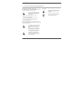
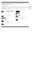
The warning symbol means that the
instructions given must always be followed for your own safety.
Failure to follow these instructions may
result in injuries
Notes provide important information that
should be strictly followed when using the
device.
Trademarks
The following names are registered trademarks. For practical reasons
they are shown without trademark symbol in this manual.
- Registered trademarks
-
InPro®
Sensocheck®
Sensoface®
Calimatic®
GainCheck®
When a key is shown, its function is explained.
When a display is shown, the corresponding
information or operating instructions are provided.
Operating instructions
• Each operating instruction is preceded by a dot.
Enumerations
- Each enumeration is preceded by a dash.
Model designation
For practical purposes, the Transmitter O2 4100 PA is simply referred
to as Transmitter in this instruction manual.
Information on this instruction manual
E-3
English
1
2
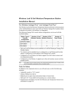
Safety information
2.1
Be sure to read and observe the following instructions!
The device has been designed in accordance with the state of the art
and complying with the applicable safety regulations.
When operating the device, certain conditions may nevertheless lead
to danger for the operator or damage to the device.
Whenever it is likely that protection has
been impaired, the device shall be made
inoperative and secured against unintended operation.
The protection is likely to be impaired if, for example:
- the device shows visible damage
- the device fails to perform the intended measurements
- after prolonged storage at temperatures above 70 ˚C
- after severe transport stress
Before recommissioning the device, a professional routine test in
accordance with EN 61010-1 must be performed. This test should be
carried out by the manufacturer.
The Transmitter O 2 4100 PA is approved
for installation in ATEX, FM Zone 1 with
measurement in Zone 0, and FM Class I
Div 1.
Before commissioning it must be proved
that the intrinsic safety is maintained when
connecting the device to other equipment,
such as segment coupler and cable.
For hazardous-area applications, the
Transmitter O 2 4100 PA may only be con nected to explosion-proof segment couplers, power supplies ....
E-4
Safety information
The Transmitter O2 4100 PA may be operated in accordance with the
FISCO model.
The stipulations of EN 60079-10: 1996 and
the following must be observed for the
installation.
In hazardous locations the Transmitter
may only be cleaned with a damp cloth to
prevent electrostatic discharge.
PROFIBUS technology
3.1
General
PROFIBUS is a digital communication system that connects different
field devices over a common cable and integrates them into a control
system. In the long term, PROFIBUS will replace the 4-20 mA technology, which only supplies pure measured values.
Advantages of the PROFIBUS technology are:
- easy and cost-saving cabling
- convenient operation over a central control station
- transmission, evaluation and control of high amounts of data from
field device to control station.
3.2
- devices installed in hazardous locations are configured and maintained from the control station
PROFIBUS is the leading open fieldbus system in Europe. Its application range covers manufacturing, process and building automation. As
open fieldbus standard to EN 50170, PROFIBUS ensures communication of different devices over one bus.
The PROFIBUS User Organization (PNO) provides for further development and maintenance of the PROFIBUS technology. It combines
the interests of users and manufacturers.
Variants and basic characteristics
PROFIBUS determines the technical and functional characteristics of
a serial bus system.
There are three PROFIBUS variants:
- PROFIBUS-FMS (FMS protocol)
- is particularly suited for exchanging large amounts of data
between control devices. It operates according to the RS 485
standard with transmission rates up to 12 MBits/sec.
- PROFIBUS-DP (decentralized peripherals)
- Masters
- control the data traffic on the bus. They send messages without
external request.
- Slaves
- are peripheral devices such as valves, drives, transmitters and
analyzers. They can react acyclically to servicing, configuration
and diagnostic tasks of the master. The central controller cyclically reads the measurement data with status.
- is tailored for communication of automation systems and distributed peripherals. It operates according to the RS 485 standard with transmission rates up to 12 MBits/sec.
- PROFIBUS-PA (process automation)
- is dedicated to the process industry. It permits connection of
sensors and actuators to a common bus even in hazardous
locations. PROFIBUS-PA has a transmission rate of
31.25 kBits/sec.
PROFIBUS distinguishes between two types of devices:
PROFIBUS technology
E-5
English
3
3.3
Definitions for PROFIBUS-PA
The bus protocol defines type and speed of the data exchange
between master and slave devices and determines the transmission
protocol of the respective PROFIBUS system.
PROFIBUS-PA permits cyclic and acyclic services.
- Cyclic services are used for transmission of measurement data
and actuating commands with status information.
3.4
- Acyclic services are used for device configuration, maintenance
and diagnostics during operation.
The device profile defines the device class and typical functionalities
with parameters, ranges and limit values.
The FISCO model developed by the German PTB for hazardous locations permits connection of several devices to one common bus and
defines permissible limits for device and cable parameters.
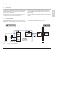
PROFIBUS-PA with the Transmitter
Process control
Service/Configuration
Master
Class 1
Cyclic
services
Master
Class 2
Acyclic
services
PROFIBUS-DP
Segment
coupler
PROFIBUS-PA
lSlave 1
Fig. 3.1
E-6
lSlave 2
Typical configuration of a PROFIBUS system with the Transmitter
PROFIBUS technology
Bus termination
lSlave n
Description
4.1
Proper use
The Transmitter is a PROFIBUS-PA analyzer. The Transmitter is used
for dissolved oxygen and temperature measurement in biotechnology,
pharmaceutical industry, as well as in the field of environment, food
processing and sewage treatment.
The protective hood provides additional protection against direct
weather exposure and mechanical damage.
The rugged molded enclosure can be wall mounted or fixed into a
control panel. It can also be mounted at a post or pipe.
The Transmitter has been designed for application with amperometric
sensors.
4.2
Technical features
Communication between measuring point and control room is via
PROFIBUS-PA. The data exchange (cyclic and acyclic) is performed
Fig. 4.1
The Transmitter can be easily replaced since the terminals are of a
plug-in design.
in accordance with the PROFIBUS-DP/V1 protocol.
System functions (hardware)
Description
E-7
English
4
4.3
Communication model
The device performance is described by function blocks according to
the PNO profile for Process Control Devices.
Fig. 4.2
E-8
The respective blocks contain different parameters and functions.
Communication model Transmitter O 2 4100 PA according to the Profile for Process Control Devices (PNO)
Description
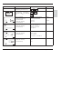
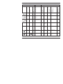
Profile for process control devices (extract)
Type of block
Block contents
(general)
Physical Block
(PB)
Device description
Block contents (detailed)
Measurement procedure, device configuration
English
4.4
Serial number, manufacturer name
Operating state (run, maintenance, ...)
Global status, diagnostics information
Transducer
Block (TB)
Measurement proce- Process variable (plain text and unit)
dure with interpretaNumber of measurement ranges (MR), start and end value of MR, active MR
tion
Sampling rate of measured values
Control
Transducer
Block
Control of device
functions
Transfer Transducer Block
Pre-processing of a Measured value pre-processing
measured value
Temperature compensation
Transducer
Limit Block
Limit monitoring
Uncorrected measured value with status
Status of function execution of respective Transducer Blocks
Calibration data
Selection of processing function
Block (TB) for limit setting
Threshold, effective direction, hysteresis
On-delay, off-delay
Reset behavior, reset confirmation
Limit status (active, not active)
Description
E-9
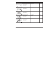
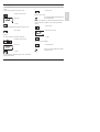
Type of block
Block contents
(general)
Block contents (detailed)
Analog Input (AI) Measured value
Currently measured value with status and scale
Function Block
Rise time, hysteresis of AI limits
Upper/lower alarm limit
Upper/lower warning limit
Switchover manual/automatic operation, measured value simulation
Fail-safe behavior
Discrete Input
(DI)
Digital input
Switchover manual/automatic operation
Limit value message/status
Function Block
Signal inversion
Fail-safe behavior
Transducer
Alarm Block
Signaling of states
and events
Required maintenance, function check, errors, limit values incl. summing
Logbook Function Block
Registration of
states and events
Power on, power off, reset
State of execution
Navigation through entries
Tab. 4.1:
E-10
Profile for Process Control Devices (function contents)
Description
Assembly
5.1
Package contents and unpacking
Unpack the device carefully. Check the shipment for transport damage
and completeness.
- This instruction manual
The package should contain:
- Floppy disk with GSD file METT7533.GSD
- Front unit of Transmitter
- Bag containing small parts:
English
5
- Short instruction sheet
- Lower case
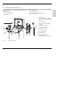
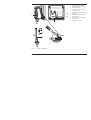
1
Jumper (2 piece)
2
Washer (1 piece): for conduit mounting: Place washer between enclosure
and nut
3
Cable ties (3 pieces)
4
Hinge pin (1 piece): insertable from
either side
5
Enclosure screws (4 pieces)
6
Sealing inserts (3 pieces)
7
Rubber reducer (1 piece)
8
Cable glands (3 pieces)
9
Filler plugs (3 pieces)
10 Gaskets (3 pieces)
11 Hexagon nuts (3 pieces)
12 Sealing plugs (2 pieces):
for sealing in case of wall mounting
Fig. 5.1
Assembling the enclosure
Assembly
E-11
5.2
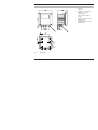
Mounting plan
1 Cable gland
(3 pieces)
2 Breakthroughs for cable gland or
conduit 1/2“, ø = 21.5 mm
(2 breakthroughs)
Cable glands and conduits not
included!
3 Breakthroughs for pipe mounting
(4 breakthroughs)
4 Breakthroughs for wall mounting
(2 breakthroughs)
Fig. 5.2
E-12
Mounting plan
Assembly
1 Screws (4 pieces)
2 Gasket (1 piece)
3 Panel
4 Span pieces (4 pieces)
English
5 Threaded sleeves (4 pieces)
Fig. 5.3
ZU 0275 panel-mount kit, panel cutout 138 x 138 mm (DIN 43700)
1 ZU 0276 protective hood (if required)
2 Hose clamps with worm gear drive to
DIN 3017 (2 pieces)
3 Pipe-mount plate (1 piece)
4 For vertical or horizontal posts or
pipes
5 Self-tapping screws (4 pieces)
Fig. 5.4
ZU 0274 pipe-mount kit
Assembly
E-13
1 Protective hood
Fig. 5.5
E-14
ZU 0276 protective hood for wall and pipe mounting
Assembly
6
Installation and connection
6.1
Information on installation
Be sure to observe the technical specifica
tions and input ratings during installation.
English
Installation may only be carried out by
trained experts in accordance with this
instruction manual and as per applicable
local and national codes.
-
According to the PTB FISCO model, the
limits of the permissible parameter range
must be observed for connection in a hazardous location.
See PROFIBUS Technical Guidelines PNO
Order No.: 2.091
Be sure not to notch the conductor when
stripping the insulation.
For easier installation, the terminal strips are of a plug-in design. The
terminals are suitable for single wires and flexible leads up to 2.5 mm2
(AWG 14).
A special twisted and shielded two-wire cable (e.g. Siemens) is used
as bus cable.
Division 2 wiring
The connections to the Transmitter must be installed in accordance
with the National Electric Code (ANSI-NFPA 70) Division 2 hazardous
(classified) location non-incendive wiring techniques.
Installation and connection
E-15
1 Connection leads PROFIBUS-PA
2 Area for placing the screwdriver to
pull out the terminals
3 Cover for DO sensor and temperature probe terminals
4 Pulling out the terminal blocks using a
screwdriver
5 Recommended stripping lengths for
multi-core cables
6 Recommended stripping lengths for
coaxial cables
7 Cable laying in the device
Fig. 6.1
E-16
Information on installation
Installation and connection
Terminal assignments
English
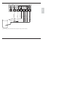
6.2
Fig. 6.2
6.3
Terminal assignments of the Transmitter
Overview of the Transmitter
1 Inputs for 2 different
DO sensors
2 Input for temperature probe
3
3 PROFIBUS-PA,
protected against polarity reversal
2
Fig. 6.3
Inputs and outputs
Installation and connection
E-17
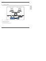
E-18
Typical wiring of InPro 6900 trace sensor for low-level range (VP cable connection)
Installation and connection
RTD
white (E)
RTD
green (F)
blue (D)
gray (C)
n. c.
shield
yellow/green (S)
annode
red (B)
transparent (A)
Fig. 6.4
cathode hi
Dissolved oxygen measurement
cathode lo
6.4
Fig. 6.5
Typical wiring of InPro 6800 sensor for high-level range (VP cable connection)
Installation and connection
E-19
white (E)
green (F)
blue (D)
gray (C)
yellow/green (S)
red (B)
transparent (A)
English
RTD
RTD
n. c.
shield
annode
cathode hi
cathode lo
7
Commissioning
7.1
Checklist
Commissioning may only be carried out by
trained experts.
Before commissioning the Transmitter O
4100 PA, the following requirements must
be met:
2
- The device must not show any damage.
- When recommissioning the device after a
repair, a professional routine test in accordance with EN 61010-1 must be performed.
- It must be proved that the intrinsic safety is
maintained when connecting the device to
other equipment.
- It must be ensured that the device is configured in accordance with the connected
peripherals.
- All connected voltage and current sources
must correspond to the technical data of the
device.
- The device must only be connected to
explosion-proof segment couplers, power
supplies, ...
E-20
Commissioning
Operation
8.1
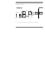
Operation possibilities
Process control
Service/Configuration
Master
Class 1
Cyclic
services
English
8
Master
Class 2
Acyclic
services
PROFIBUS-DP
Segment
coupler
PROFIBUS-PA
lSlave 1
Fig. 8.1
lSlave 2
Bus termination
lSlave n
System configuration
The device can be operated as follows:
- using the keypad on the device
- using an operating tool in the service station
Operation
E-21
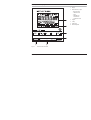
8.2
Operation using keypad on the device
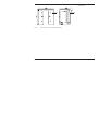
1 Display
2 Mode indicators (no keys)
- Measuring mode
- Calibration mode
- Alarm
- PROFIBUS-PA
communication
- Configuration mode
3 Keypad
4 Coding
5 Rating plate
6 Model designation
Fig. 8.2
E-22
Front view of the Transmitter
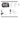
Operation
Display
2
3 4
5
6
7
20
8
9
10
1
Mode code entry
2
Display of measured vari- 12 Proceed with enter
able
3
Temperature
4
Not connected
14 Lower display
5
Limit values
15 Manual temp indicator
Alarm
16 Hold state active
Sensocheck
17 Wait
11 6
19
7
12 8
13 9
18
13 Bar for device status
Calibration
18 Sensor data
Interval/
response time
19 Main display
10 Not connected
17 16 15
Fig. 8.3
11 Measurement symbols
English
1
20 Sensoface
14
Transmitter display
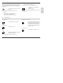
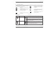
Keypad functions
Change digit
Measurement
Calibration
Configuration
Prompt in display:
Continue in program sequence
Configuration: Confirm entries,
next configuration step
Further key combinations are explained in the
respective function descriptions.
Select digit position
Selected position flashes
Operation
E-23
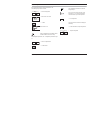
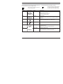
8.3
Mode code
After pressing meas and/or cal you can enter one of the following
mode codes to access the designated mode:
conf, 0000
conf, 1200
cal, 1001
cal, 1105
8.4
Error Info
Configuration mode
Zero point calibration
Product calibration
Cal Info
Adjusting temp probe
Calibration mode
Display sensor current (uncompensated)/
temperature
Safety functions
Sensocheck, Sensoface sensor monitoring
Sensocheck monitors the sensor and lines for short circuits or open
connections.
Sensocheck can be switched off.
Sensoface provides information on the sensor
condition.
The zero point, slope and response time during calibration are evaluated.
The three Sensoface indicators provide the
user with information about wear and required
maintenance of the sensor.
GainCheck manual device self-test
A display test is carried out, the software version is displayed and the
memory and measured value transfer are checked.
Start GainCheck manual device self-test
Automatic device self-test
The automatic device self-test checks the memory and measuredE-24
cal, 0000
cal, 1015
cal, 1100
cal, 2222
Operation
value transfer. It runs automatically in the background at fixed intervals.
Hold state
- Configuration
The Hold state is a safety state that is activated in the case of interventions such as configuration and calibration. The Transmitter freezes
the last valid measured value and sends a status message to the
control system.
- Mode code 1200 = Configuration mode
The measured value and Hold are displayed alternately
This symbol indicates that the device is in the
“Hold” state.
The Hold state is activated by the following mode codes:
• End the Hold state
After 20 sec (for measured value stabilization) the device returns to
measuring mode.
- Calibration
- Mode code 1015 = Temp probe adjustment
- Mode code 1100 = Calibration mode
- Mode code 2222 = Display of sensor potential
8.5
Mode indicators
Measuring mode
PROFIBUS-PA communication
The Transmitter is in measuring mode.
The Transmitter communicates via PROFIBUS-PA and can be configured from the service station. Measured values, messages and
device identification can be downloaded at
any time. This allows integration in fully automatic process cycles.
Calibration mode
Calibration mode is active.
Configuration mode
The Transmitter is in configuration mode.
Alarm
During an error message the red alarm LED
beneath the display flashes.
The alarm response time is permanently set to 10 sec.
Operation
E-25
English
• Check whether the measured value is
plausible
8.6
Configuration
In the configuration mode the device parameters are set.
The following steps must be executed:
The configuration parameters are checked
during the input.
• Activate configuration
In the case of an incorrect input “Err” is displayed for 3 sec. The incorrect parameters
cannot be stored. Input must be repeated.
• Enter mode code “1200”
• End configuration
•
Confirm
Welcome text 3 sec
The measured value and Hold are displayed
alternately.
• End the Hold state / accept configuration or
•
During configuration the Transmitter remains
in the Hold state for reasons of safety.
For configurable parameters, see ”Configuration parameters” Page
27.
• Select or edit parameter
• Confirm entries
E-26
Operation
Repeat configuration
Configuration parameters
Action
Choices
Factory setting
Device is in Hold state.
Sensor Type A (general sensor)
Type A
• Select sensor (type A / B)
Proceed with enter
Sensor Type B (InPro6900)
Activate configuration
(simultaneously press meas and cal)
Enter mode code “1200”
(Press arrow key
to select position,
enter number using
key, confirm with
enter)
• Switch over: arrow keys
• Proceed: enter key
Selection of variable to be displayed
• Switch over: arrow keys
English
Display
Low Level
Hi-Level
High Level
With Low Level selected:
µg/l • ppb • mg/l • ppm • %
• Proceed: enter key
With High Level selected:
mg/l • ppm • %
Selection of process temp
man °C / man °F
• Switch over: arrow keys
auto °C / auto °F
• Proceed: enter key
BUS °C / BUS °F:
%
Auto °C
-20 to +150 °C or -4 to +302 °F
Selection of temp probe (NTC)
Only with Auto selected:
• Switch over: arrow keys
22 kΩ
• Proceed: enter key
30 kΩ
22 NTC
Operation
E-27
Display
Action
Choices
Factory setting
Selection of pressure measurement unit
BAR • PSI • KPA
BAR
0.000 to 9.999 bars
1.013 bars
00.00 to 45.00 g/kg or %, resp.
00.00
Selection of polarization voltage
0 mV to 800 mV
675 mV
• Switch over: arrow keys
(0 mV = Off)
• Switch over: arrow keys
• Proceed: enter key
Selection of process pressure
• Switch over: arrow keys
• Proceed: enter key
Selection of salinity
• Switch over: arrow keys
• Proceed: enter key
• Proceed: enter key
Selection of Sensocheck On, Off
On
• Switch over: arrow keys
Off
• Proceed: enter key
E-28
Operation
Off
Display
Action
Choices
Factory setting
Selection of calibration mode
- Saturation (Sat)
Conc
• Switch over: arrow keys
- Concentration (Conc)
Tab. 8.1:
Selection of cal timer interval
0000 (Off)
Selection of bus address
126
English
• Proceed: enter key
Configuration parameters
Configuration is circular. To stop, press meas key.
8.7
Calibration
Calibration is used to adapt the device to the DO sensor. Depending
on the configuration, the device can be calibrated with regard to saturation or concentration. For each calibration mode, the Transmitter
suggests useful calibration parameters. Of course, they can be edited
as required.
All calibration procedures must be performed
by trained personnel.
During calibration, the output current is frozen,
limit and alarm contacts are inactive.
Note:
When a 2-point calibration is required, the zero point calibration should
be performed prior to saturation or concentration calibration, resp.
Incorrectly set parameters may go unnoticed,
but change the measuring properties.
If calibration is exited, the Transmitter remains in the Hold state for
reasons of safety. The measured value and Hold are displayed alternately. Now you can check whether the measured value is plausible
Operation
E-29
and specifically end the Hold state with enter or press cal to repeat
calibration.
If you end the Hold state, the Transmitter will return to measuring
mode after 20 sec (for the sensor to adjust).
Zero point calibration
A zero point calibration is not required for most of the biotechnological
processes. For these processes, we recommend to set the input
current for the zero point to 0.0 nA and then perform a one-point calibration (saturation). If a zero point calibration is performed, the DO
Display
sensor should remain for at least 10 to 30 minutes in the calibration
medium in order to obtain accurate values. A drift check is not
performed.
Zero point current should be < 0.5 % of air current. The display
(secondary: measured value, main: entered value) does not change
until an input current is entered for the zero point.
When measuring in an oxygen-free medium, the displayed current can
be taken directly.
When the zero point has changed, the slope is automatically adjusted
so that the 100% point remains valid.
Zero point calibration – Action
Selection / Remarks
• Activate calibration
(press cal key)
1001
• Enter mode code “1001”
(Press arrow key
to select position,
enter number using
key, confirm with enter)
• Place sensor in oxygen-free medium
Lower display: actually measured current
Main display: value for zero point
• Confirm with enter or correct using arrow keys
and then confirm with enter
Display of slope
After end of calibration, the Transmitter
remains in Hold state for approx. 20 sec.
Display of new zero point
• Place sensor in process
The oxygen value is displayed.
• End calibration with enter
Saturation calibration
E-30
Operation
Action
Selection / Remarks
Select calibration, enter mode code “1100”
cal key, arrow keys
• Enter relative humidity
Default for aqueous media rH = 100 %
English
Display
• Proceed with enter
• Enter calibration pressure, proceed with enter
Default: configured process pressure
• If temperature display follows, temperature can be entered
manually, see remarks
If "man" or "BUS" has been selected during configuration, the configured process
temperature will be displayed.
The internal temperature probe is not
used.
• Proceed with enter
• Automatic drift check:
Measurement
Display of input current
(temperature-compensated)
and of measuring temp
Drift check can be stopped after > 10 sec
by pressing cal (accuracy reduced).
• Change default value if required
Default: last value entered
• Display of new slope and zero point related to 25°C at 1013
mbars
After end of calibration, the oxygen value
is displayed for approx. 20 sec. Then the
Transmitter will return to measuring
mode.
• End calibration with enter
Operation
E-31
Concentration calibration
Display
Action
Selection / Remarks
Select calibration, enter mode code “1100”
cal key, arrow keys
Place DO sensor in air for calibration
Default for aqueous media rH = 50 %
• Enter relative humidity
• Proceed with enter
• Enter calibration pressure, proceed with enter
• If temperature display follows, temperature can be entered
manually, see remarks
• Proceed with enter
Default: normal pressure 1013 mbars. If
"man" or "BUS" has been selected during
configuration, "25 °C" will be displayed.
The internal temperature probe is not
used.
• Measurement
Display of input current
(temperature-compensated)
and of measuring temp
Drift check can be stopped after > 10 sec
by pressing cal (accuracy reduced).
• Default value calculated from rel. humidity,
cal pressure and cal temp
(theoretical concentration for saturation)
Edit default value if required.
Display of new slope and zero point related to 25°C at 1013 mbars After end of calibration, the oxygen value
is displayed for approx. 20 sec. Then the
• End calibration with enter
Transmitter will return to measuring
mode.
E-32
Operation
Product calibration
Action
Selection / Remarks
Select calibration, enter mode code “1105”
cal key, arrow keys
Product calibration 1st step
Display (approx. 3 sec)
• Take sample and store value
Now the sample can be measured in the
lab. The Transmitter is in measuring
mode.
English
Display
• Proceed with enter
• Measuring mode
While the sample value is determined, the device is in measuring mode. From the flashing CAL mode indicator you see that
sample calibration has not been terminated.
• When the sample value has been determined,
call up the product calibration once more
(CAL key, mode code 1105).
Product calibration 2nd step
Display (approx. 3 sec)
Enter lab value. The new slope is calculated.
Arrow keys
Then zero point and slope are displayed as for ordinary calibration.
Operation
E-33
Adjusting temp probe
Wrong settings change the measurement
properties!
The following steps must be executed:
• Activate calibration
• Enter mode code “1015”
and confirm
• Measure the temperature of the process
medium using an external thermometer
A welcome text ("CAL TMP") is displayed for
3 sec.
• Then enter the determined temperature
value in the main display (arrow keys)
If the value of the main display is set to the
value of the secondary display, a correction is
not made.
• Confirm with enter
HOLD will be deactivated after 20 sec.
E-34
Operation
Operating tool
For parameter setting, commissioning and diagnostics of the Transmitter via PROFIBUS, we recommend operating tools such as
SIMATIC-PDM Version 5 or higher.
8.9
The current device description is included.
Measurement
English
8.8
Measuring mode
Error Info
In the measuring mode the main display shows the configured process
variable and the lower display the temperature.
“Error Info” shows the most recent error message.
The Transmitter returns to measuring mode,
also from configuration or calibration mode
(after a relax time for measured-value stabilization, if required).
• Activate “Error Info” function
• Mode code
Cal Info
“Cal Info” shows the slope and zero point current.
• Activate “Cal Info” function
• Mode code
• Confirm
The error message is displayed for approx. 20 sec. After that the
message will be deleted.
• End “Error Info”
•
Confirm
“Cal Info” shows the current calibration data for approx. 20 sec.
• End “Cal Info”
Operation
E-35
9
Diagnostics
9.1
Sensocheck, Sensoface
Three Smileys provide information on wear and required maintenance.
This does not affect the measurement process.
Sensoface provides information on the status
of the sensor.
The zero point, slope and response time during calibration are evaluated.
A Smiley can only be displayed when Sensocheck has been activated.
The worsening of a Sensoface criterion leads
to the devaluation of the Sensoface indicator
(average/poor).
An improvement of the Sensoface indicator
can only take place after calibration or removal
of a sensor defect.
The Sensoface status does not influence the
measured value display.
The basis for accurate Sensoface indication is
proper calibration.
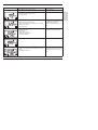
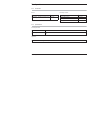
Sensoface displays
Display
Problem
Sensor response time
Status
The sensor adjusts slowly to the measured value. Maybe it has not been polarized
sufficiently. You should consider replacing the membrane module and electrolyte.
The sensor adjusts very slowly to the measured value. Correct measurement is no
longer ensured. If this occurs in spite of sufficient polarization, you should replace the
membrane module and electrolyte.
Slope
Sensor slope is still okay. However, membrane module and electrolyte should be
replaced soon.
Sensor slope has reached a value which no longer ensures proper measurement.
You should replace membrane module and electrolyte.
E-36
Diagnostics
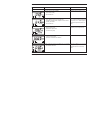
Display
Problem
Status
Calibration timer
Over 80 % of the calibration interval has already past.
Sensor defect
Tab. 9.1:
9.2
English
The calibration interval has been exceeded.
Check membrane module and electrolyte and the sensor connections.
Sensoface display
PROFIBUS-PA limit monitoring
The Transmitter is equipped with two limit blocks that can be separately configured for temperature and/or the process variable.
Configuration is only performed via the bus.
The limit conditions are transmitted cyclically.
Hysteresis, effective direction, on and off delay can be configured.
Limit value setting and output of limit messages is via the PROFIBUS-PA.
When this symbol is displayed, limit block 1 is
active.
When this symbol is displayed, limit block 2 is
active.
Diagnostics
E-37
9.3
Error messages
When one of the following error messages is displayed, the device can
no longer determine the measured variable correctly.
The alarm response time is permanently set to 10 sec.
During an error message the red alarm LED
beneath the display flashes.
Error No.
Display (flashing)
Err 01
Problem
DO sensor
The error messages in the display are sorted
according to their priority. A higher-priority
message overlays a lower-priority message.
Possible causes
- Sensor defect
- Incorrect sensor connected
- Measurement range (%) exceeded
Current range (mA) exceeded
Err 02
DO sensor
- Sensor defect
- Measured concentration value lower than 0 mg/l (ppm) or higher than 50
mg/l (ppm)
Err 03
Temperature probe
- Open or short circuit in temperature probe
- Measured temperature below -10 °C or above +150 °C
Err 33
DO sensor
- Membrane defective
Err 98
System error
- Configuration or calibration data defective; completely reconfigure and
recalibrate the device
Err 99
Factory settings
- Memory error in device program (PROM defective)
- EEPROM or RAM defective
This error message only occurs in the case of a complete defect. The Transmitter must be repaired and recalibrated at the factory.
Tab. 9.2:
E-38
Error messages
Diagnostics
Calibration error messages
Display (flashing)
Problem
Possible causes
Sensor slope out of range
- Wrong calibration values specified (relative humidity, pressure, saturation, concentration)
Calibration was canceled
after approx. 12 minutes,
because the sensor drift
was too large.
- Sensor defective or dirty
- No electrolyte in the sensor
- Sensor cable insufficiently shielded or defective
- Strong electric fields influence the measurement
- Temperature fluctuation of calibration solution
Tab. 9.3:
Calibration error messages
Diagnostics
E-39
English
Calibration error messages only occur during
calibration.
Display messages and PROFIBUS communication
Failure
ERR SYSTEM
X
X
Configuration data defective,
Gaincheck
2
0000 11xx
Failure
ERR PARAMETERS
X
Err 98
X
Memory error
(RAM, ROM, EPROM)
3
0000 11xx
Failure
ERR MEMORY
X
Err 01
X
Measurement range violation
4
0100 0111
0100 1111
Failure
ERR SAT VALUE
X
Err 02
X
Measurement range violation
5
0100 0111
0100 1111
Failure
ERR CONC VALUE
X
Err 03
X
Temp range violation
Temperature probe
6
0100 0111
0100 1111
Failure
ERR TEMP VALUE
X
Membrane defective
7
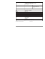
0100 0111
0100 1111
Failure
ERR SENSOCHECK
X
Diagnostics
X
(factory setting)
Physical Block (PB)
0000 11xx
Logbook entry
Analog input status
1
(factory setting)
No. of binary message
(logbook)
Factory settings defective
Text of binary
message
For comments
see Pg 38 through Pg 39
X
Err 98
Err 33
E-40
Communication via PROFIBUS
LED
Err 99
Cause
Sensoface
Display message
Display pictograph
User interface / display of device
Global status
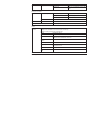
9.4
CHK ZERO/SLOPE
X
Sensor response time
9
0101 00xx
Maintenance
required
CHK EL. RESPONSE
X
Calibration timer
Cal prompt
10
0101 00xx
Maintenance
required
CAL REQUIRED
X
Calibration
11
0100 0111
0100 1111
Function
check
CAL RUNNING
X
Configuration
12
0100 0111
0100 1111
Function
check
CONF RUNNING
X
HOLD
13
(Device state = Maintenance)
0100 0111
0100 1111
Function
check
HOLD
X
HI_HI_LIM
FB analysis
14
1000 1110
Limit 1
Bit 1
HI_HI_LIMIT OXY
HI_LIM
FB analysis
15
1000 1010
Limit 1
Bit 2
HI_LIMIT OXY
LO_LIM
FB analysis
16
1000 1001
Limit 1
Bit 3
LO_LIMIT OXY
Logbook entry
Diagnostics
E-41
English
Maintenance
required
(factory setting)
0101 00xx
(factory setting)
8
Text of binary
message
Physical Block (PB)
Zero point/
Slope
Global status
Analog input status
Communication via PROFIBUS
No. of binary message
(logbook)
For comments
see Pg 38 through Pg 39
LED
Cause
Sensoface
Display message
Display pictograph
User interface / display of device
Tab. 9.4:
E-42
HI_HI_LIM
FB temperature
18
1000 1110
Limit 2
Bit 1
HI_HI_LIMIT TEMP
HI_LIM
FB temperature
19
1000 1010
Limit 2
Bit 2
HI_LIMIT TEMP
LO_LIM
FB temperature
20
1000 1001
Limit 2
Bit 3
LO_LIMIT TEMP
LO_LO_LIM
FB temperature
21
1000 1101
Limit 2
Bit 4
LO_LO_LIMIT TEMP
Logbook empty
22
Function
check
EMPTY LOGBOOK
(factory setting)
LO_LO_LIMIT OXY
Logbook entry
Limit 1
Bit 4
(factory setting)
1000 1101
Text of binary
message
Physical Block (PB)
17
Global status
Analog input status
LO_LO_LIM
FB analysis
Display messages and PROFIBUS communication
Diagnostics
Communication via PROFIBUS
No. of binary message
(logbook)
For comments
see Pg 38 through Pg 39
LED
Cause
Sensoface
Display message
Display pictograph
User interface / display of device
9.5
Diagnostics functions
Cal Info
• End “Error Info”
• Activate “Cal Info” function
Display of sensor current
• Mode code
•
Confirm
The current calibration data are displayed for approx. 20 sec.
• End “Cal Info”
This symbol indicates that the temperature will
be manually specified.
During sensor maintenance it is useful to directly indicate the sensor
current. This allows, for example, to check sensor response after
cleaning.
• Select function
• Enter mode code “2222”
Error Info
“Error Info” shows the most recent error message.
• Confirm
• Activate “Error Info” function
The sensor current is displayed.
• Mode code
•
Confirm
• End display mode
During sensor current display the Transmitter
is in the Hold state.
The error message is displayed for approx. 20 sec. After that the
message will be deleted.
Diagnostics
E-43
English
“Cal Info” shows the slope and zero point current.
GainCheck manual device self-test
A display test is carried out, the software version is displayed and the
memory and measured value transfer are checked.
• Start GainCheck manual device self-test
Automatic device self-test
The automatic device self-test checks the memory and measuredvalue transfer. It runs automatically in the background at fixed intervals.
E-44
Diagnostics
10 Maintenance and cleaning
10.1 Maintenance
English
The Transmitter contains no user repairable components.
10.2 Cleaning
To remove dust, dirt and spots, the external surfaces of the Transmitter may be wiped with a soft cloth moistened with water.
A mild household cleaner may also be used if necessary.
Maintenance and cleaning
E-45
11 Appendix
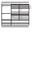
11.1 Product line
Devices
Mounting accessories
Model designation
Ref. No.
Accessories
Ref. No.
Transmitter O2 4100 PA for hazardous- and
safe-area applications
52 121 091
ZU 0274 pipe-mount kit
52 120 741
ZU 0275 panel-mount kit
52 120 740
ZU 0276 protective hood
52 120 739
11.2 Specifications
General specifications
Manufacturer / ID
Mettler-Toledo GmbH / METT
Model designation /
ID
Transmitter O2 4100 PA /
2533
Applications
Measurement of dissolved oxygen and temperature
E-46
Appendix
Sensor Type A (High Level):
InPro 6800
Sensor Type B (Low Level):
InPro 6900
Range 1
Measuring current
-2 to +600 nA, resolution 10 pA
(low level)
Saturation (-10 °C to +80 °C)
0.0 to 120.0 %
Meas. error1,2,3
0.5 % meas. value + 0.1 % saturation
Concentration
(-10 °C to +80 °C)
0000 to 9999 µg/l
English
DO input
0000 to 9999 ppb
0000 to 9999 ppm
0000 to 9999 mg/l
Meas. error1,2,3
0.5 % meas. value + 5 µg/l or 5 ppb, resp.
Range 2
Measuring current
-2 to +1800 nA, resolution 30 pA
(high level)
Saturation (-10 °C to +80 °C)
0 to 500 %
Meas. error1,2,3
0.5 % meas. value + 0.5 % saturation
Concentration
(-10 °C to +80 °C)
0.0 to 50.00 mg/l
1,2,3
Meas. error
Polarization voltage
0 to 1000 mV
Process pressure
0.000 to 9.999 bars
0.0 to 50.00 ppm
0.5 % meas. value
+ 50 µg/l or 50 ppb, resp.
999.9 kPa
145.0 psi
Salt correction
0.00 to 45.00 g/kg
Sensocheck
Monitoring for short circuits or open circuits (can be disabled)
Appendix
E-47
Sensor standardization (cal)
Zero point calibration
Calibration with entry of oxygen saturation
Calibration with entry of oxygen concentration at saturation
Product calibration
Calibration range
Zero
± 2 nA
Slope
Sensor Type A: 25 to 130 nA
Sensor Type B: 200 to 550 nA
(InPro6900)
Cal timer*
0 to 9999 h
Pressure correction
Calibration pressure to be entered manually or via PROFIBUS
Temperature input
NTC 22kΩ or NTC 30 kΩ, 2-wire connection, ± 5 K adjustable
Range
-20.0 to +150.0 °C / -4 to +302 °F
Resolution
0.1 °C / 1 °F
Meas. error1,2,3
< 0.5 K (< 1 K bei > 100 °C)
Temperature compensation
Automatic with NTC or manual temperature
Logbook
Recording of error messages
Storage capacity
40 entries, can be read out via Profibus (see profile description)
Limit values
Cyclical discrete signal (DI) via Profibus (see profile description)
User-defined via Profibus for:
Oxygen saturation
Oxygen concentration
Temperature
Alarms and messages
Binary messages to PNO profile 3.0
Signalling via PROFIBUS and logbook entry
*) Configurable
1) To IEC 746 Part 1, at nominal operating conditions
E-48
Appendix
2) ± 1 count
3) Plus sensor error
Temperature
Electromagnetic compatibility
Operation
-20 to +55 °C
Transport and storage
-20 to +70 °C
Emitted interference
EN 61 326 Class B
Immunity to interference
EN 61 326, EN 61 326/A1
Ingress protection
Enclosure
IP 65
Explosion protection
PROFIBUS-PA according to FISCO model of II 2(1) G EEx ia IIC T4, FISCO
PTB
Data retention
English
Conditions for use
FM
IS, Class I Div1, Group A, B, C, D T4 FISCO
I / 1[0] / AEx ib [ia] / IIC / T4 FISCO
NI, Class I Div2, Group A, B, C, D T4 NIFW
Parameters and calibration data
> 10 years
EEPROM
Construction
Dimensions
Height
144 mm
Width
144 mm
Depth
105 mm
Weight
Approx. 1 kg
Material
PBT (polybutylene terephtalate)
Color
Bluish gray
Assembly
Wall mounting
Post/pipe mounting
Panel mounting
RAL 7031
on pipe with 40 to 60 mm diameter,
on square post with 30 to 45 mm edge length
Cutout to DIN 43 700
Sealed against panel
Appendix
E-49
Electrical connection Cable glands
3 breakthroughs
for included cable glands
2 breakthroughs
for NPT 1/2” or Rigid Metallic Conduit or cable
glands
Measured value display
µg/l, mg/l, ppb, ppm, %, temperature
Display and user interface
Display
LC display, 7-segment
Operation
3 Sensoface states
Good / average / poor
5 mode indicators
meas / cal / alarm / online / conf
Alarm LED
Error message
5 keys
meas / cal / up / right / enter
Operating tool
Device description (DD) implemented in SIMATIC PDM
Interface
PROFIBUS-PA com- Digital communication by current modulation of supply current
munication
Reading of device identification, measured values, status and message
Reading and writing of parameter and configuration data
Protocol
E-50
Appendix
PROFIBUS-PA (DPV1)
Connection
Via segment coupler to SPC, PC, PCS
Profile
PNO directive: PROFIBUS-PA,
Profile for Process Control Devices, Version 3.0
Physical
interface
To IEC 1158-2
Address range
1 to 126, default: 126
Supply voltage
FISCO bus supply: 9 to 17.5 V
Linear barrier: 9 to 24 V
Current consumption
< 13.2 mA
Max. current in case of fault
(FDE)
< 17.6 mA
English
Appendix
E-51
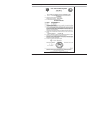
11.3 ATEX EC-Type-Examination Certificate
E-52
Appendix
English
Appendix
E-53
E-54
Appendix
English
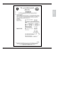
11.4 Declaration of Conformity
Declaration of conformity
Konformitätserklärung
Déclaration de conformité
We/Wir/Nous
0820
Mettler-Toledo GmbH, Process Analytics
Im Hackacker 15
8902 Urdorf
Switzerland
declare under our sole responsibility that the product,
erklären in alleiniger Verantwortung, dass dieses Produkt,
déclarons sous notre seule responsabilité que le produit,
Description
Beschreibung/Description
EMC Directive/EMV-Richtlinie
Directive concernant la CEM
O2-4100 PA
to which this declaration relates is in conformity with the following standard(s) or other
normative document(s).
auf welches sich diese Erklärung bezieht, mit der/den folgenden Norm(en) oder
Richtlinie(n) übereinstimmt.
auquel se réfère cette déclaration est conforme à la (aux) norme(s) ou au(x)
document(s) normatif(s).
94/9/EG
Prüf- und Zertifizierungsstelle ZELM
ZELM 02 ATEX 0073
D-38124 Braunschweig, ZELM 0820
89/336/EWG
SR 734.5, VEMV
Low-voltage directve/Niederspannungs-Richtlinie/
Directive basse tension
73/23/EWG
SR 734.26, NEV
Explosionsschutzrichtlinie
Explosion Protection / Protection contre les explosions
Norm/Standard/Standard
Place and Date of issue
Ausstellungsort / - Datum
Lieu et date d’émission
EN 50 014 + A1 + A2:
EN 50 020:
DIN EN 61326
DIN EN 61326 / A1
EN 61010 Teil 1 / 03.93
EN 61010-1/ A2 / 07.95
1997
1994
/ VDE 0843 Teil 20:
/ VDE 0843 Teil 20 / A1:
/ VDE 0411 Teil 1:
/ VDE 0411 Teil 1 / A1:
1998-01
1999-05
1994-03
1996-05
Urdorf, August 2, 2004
Mettler-Toledo GmbH, Process Analytics
Waldemar Rauch
General Manager PO Urdorf
Artikel Nr.: 52960173 KE
Christian Zwicky
Head of Marketing
52960173KE-4100PA-Internet-2.doc
Version b
Appendix
E-55
11.5 FM Control Drawing
),6&2UXOHV
7KH),6&2&RQFHSWDOORZVWKHLQWHUFRQQHFWLRQRILQWULQVLFDOO\VDIHDSSDUDWXVWRDVVRFLDWHGDSSDUDWXV
QRWVSHFLILFDOO\H[DPLQHGLQVXFKFRPELQDWLRQ7KHFULWHULRQIRUVXFKLQWHUFRQQHFWLRQLVWKDWWKH
YROWDJH9PD[WKHFXUUHQW,PD[DQGWKHSRZHU3LZKLFKLQWULQVLFDOO\VDIHDSSDUDWXVFDQUHFHLYHDQG
UHPDLQLQWULQVLFDOO\VDIHFRQVLGHULQJIDXOWVPXVWEHHTXDORUJUHDWHUWKDQWKHYROWDJH8R9 RF 9WWKH
FXUUHQW,R,VF ,WDQGWKHSRZHU3RZKLFKFDQEHSURYLGHGE\WKHDVVRFLDWHGDSSDUDWXVVXSSO\XQLW
,QDGGLWLRQWKHPD[LPXPXQSURWHFWHGUHVLGXDOFDSDFLWDQFH& LDQGLQGXFWDQFH/LRIHDFKDSSDUDWXV
RWKHUWKDQWKHWHUPLQDWRUVFRQQHFWHGWRWKH)LHOGEXVPXVWEHOHVVWKDQRUHTXDOWRQ)DQG+
UHVSHFWLYHO\
,QHDFK,6)LHOGEXVVHJPHQWRQO\RQHDFWLYHVRXUFHQRUPDOO\WKHDVVRFLDWHGDSSDUDWXVLVDOORZHGWR
SURYLGHWKHQHFHVVDU\SRZHUIRUWKH)LHOGEXVV\VWHP7KHDOORZHGYROWDJH8R 9RF 9WRIWKH
DVVRFLDWHGDSSDUDWXVXVHGWRVXSSO\WKHEXVPXVWEHOLPLWHGWRWKHUDQJHRI9GFWR9GF$OO
RWKHUHTXLSPHQWFRQQHFWHGWRWKHEXVFDEOHKDVWREHSDVVLYHPHDQLQJWKDWWKHDSSDUDWXVLVQRW
DOORZHGWRSURYLGHHQHUJ\WRWKHV\VWHPH[FHSWWRDOHDNDJHFXUUHQWRI$IRUHDFKFRQQHFWHG
GHYLFH6HSDUDWHO\SRZHUHGHTXLSPHQWQHHGVDJDOYDQLFLVRODWLRQWRLQVXUHWKDWWKHLQWULQVLFDOO\VDIH
)LHOGEXVFLUFXLWUHPDLQVSDVVLYH
7KHFDEOHXVHGWRLQWHUFRQQHFWWKHGHYLFHVQHHGVWRFRPSO\ZLWKWKHIROORZLQJSDUDPHWHUV
/RRSUHVLVWDQFH5
NP
,QGXFWDQFHSHUXQLWOHQJWK/
P+NP
&DSDFLWDQFHSHUXQLWOHQJWK&
Q)NP
&
&
OLQHOLQH&
OLQHVFUHHQLIERWKOLQHVDUHIORDWLQJ
RU
&
&
OLQHOLQH&
OLQHVFUHHQLIWKHVFUHHQLVFRQQHFWHGWRRQHOLQH
/HQJWKRIVSXU&DEOHPD[P
/HQJWKRIWUXQNFDEOHPD[NP
/HQJWKRIVSOLFHPD[P
7HUPLQDWRUV
$WHDFKHQGRIWKHWUXQNFDEOHDQDSSURYHGOLQHWHUPLQDWRUZLWKWKHIROORZLQJSDUDPHWHUVLVVXLWDEOH
5 & )
6\VWHPHYDOXDWLRQ
7KHQXPEHURISDVVLYHGHYLFHVOLNHWUDQVPLWWHUVDFWXDWRUVFRQQHFWHGWRDVLQJOHEXVVHJPHQWLVQRW
OLPLWHGGXHWR,6UHDVRQV)XUWKHUPRUHLIWKHDERYHUXOHVDUHUHVSHFWHGWKHLQGXFWDQFHDQG
FDSDFLWDQFHRIWKHFDEOHQHHGQRWWREHFRQVLGHUHGDQGZLOOQRWLPSDLUWKHLQWULQVLFVDIHW\RIWKH
LQVWDOODWLRQ
IQVWDOODWLRQ1RWHV)RU),6&2DQG(QWLW\&RQFHSWV
7KH ,QWULQVLF
6DIHW\
(QWLW\
FRQFHSW
DOORZV
WKH LQWHUFRQQHFWLRQ
RI
)0 $SSURYHG
,QWULQVLFDOO\
VDIH
GHYLFHV
ZLWK HQWLW\
SDUDPHWHUV
QRW VSHFLILFDOO\
H[DPLQHG
LQ FRPELQDWLRQ
DV D V\VWHPV
ZKHQ
3R 3 L &
&
R 8 R RU 9RF RU
9W 9 PD[
,R RU
,VF
RU ,W ,PD[
D RU
&L &FDEOH )RU LQGXFWDQFH
XVH HLWKHU
/D RU
/R /L / FDEOH
RU /H5H
/D5
D RU /R 5R DQG
/L5L / D 5 D RU /R5R
7KH ,QWULQVLF
6DIHW\
),6&2
FRQFHSW
DOORZV
WKH LQWHUFRQQHFWLRQ
RI
)0 DSSURYHG
,QWULQVLFDOO\
VDIH
GHYLFHV
ZLWK ),6&2
SDUDPHWHUV
QRW VSHFLILFDOO\
H[DPLQHG
LQ FRPELQDWLRQ
DV D V\VWHP
ZKHQ
8 R RU 9RF RU 9 W 9 PD[
,R RU
,VF
RU ,W ,PD[
3 R 3L
'XVWWLJKW
FRQGXLW
VHDOV
PXVW
EH XVHG ZKHQ
LQVWDOOHG
LQ &ODVV
,, DQG &ODVV
,,, HQYLURQPHQWV
&RQWURO
HTXLSPHQW
FRQQHFWHG
WR WKH $VVRFLDWHG
$SSDUDWXV
PXVW
QRW XVH
RU JHQHUDWH
PRUH
WKDQ
9UPV
RU 9GF
VKRXOG
EH LQ DFFRUGDQFH
ZLWK $16,,6$
53
H[FHSW
FKDSWHU
IRU ),6&2
,QVWDOODWLRQV
,QVWDOODWLRQ
,QVWDOODWLRQ
RI ,QWULQVLFDOO\
6DIH 6\VWHPV
IRU +D]DUGRXV
&ODVVLILHG
/RFDWLRQVµ
DQG WKH 1DWLRQDO
(OHFWULFDO
&RGH
$16,1)3$
6HFWLRQV
DQG 7KH FRQILJXUDWLRQ
RI DVVRFLDWHG
$SSDUDWXV
PXVW
EH )0 $SSURYHG
XQGHU
WKH
DVVRFLDWHG
FRQFHSW
$VVRFLDWHG
$SSDUDWXV
PDQXIDFWXUHU
V
LQVWDOODWLRQ
GUDZLQJ
PXVW
EH IROORZHG
ZKHQ
LQVWDOOLQJ
WKLV
HTXLSPHQW
6HULHV
DUH $SSURYHG
IRU &ODVV
=RQH
DSSOLFDWLRQV
,I FRQQHFWLQJ
$([ >LE@
7KH 23$2 H))
DVVRFLDWHG
$SSDUDWXV
RU $([
LE ,6 $SSDUDWXV
WR WKH 23$2H))
6HULHV
WKH ,6 FLUFXLW
LV RQO\
VXLWDEOH
IRU &ODVV
=RQH
RU &ODVV
=RQH
DQG
LV QRW VXLWDEOH
IRU &ODVV
=RQH
RU &ODVV
'LYLVLRQ
+D]DUGRXV
&ODVVLILHG
/RFDWLRQV
WR GUDZLQJ
ZLWKRXW
SULRU )0 $SSURYDOVDXWKRULVDWLRQ
1R UHYLVLRQ
6LPSOH
$SSDUDWXV
LV GHILQHG
DV D GHYLFH
WKDW GRHV QRW JHQHUDWHV
PRUH
WKDQ
9
$ RU
P:
E-56
Appendix
English
Appendix
E-57
12 Index
A
Analog Input (AI) Function Block, E-10
D
Declaration of Conformity, E-55
Applications, E-46
Device description, E-7
Assembly
Device self-test
Enclosure, E-11
Panel-mount kit (ZU 0275), E-13
Automatic, E-24, E-44
Manual, E-24, E-44
Pipe-mount kit (ZU 0274), E-13
Diagnostics functions, E-43
Protective hood (ZU 0276), E-14
Discrete Input (DI) Function Block, E-10
Stratos, E-12
Display, E-23
Display messages and PROFIBUS communication, E-40
C
Cal Info, E-35, E-43
Display sensor current, E-43
Calibration, E-29
Division 2 wiring, E-15
Dissolved oxygen measurement, E-18
Sensoface, E-36
Calibration error message, E-39
Certificate of Conformity, E-52
E
Error Info, E-35, E-43
Error message, E-38
Cleaning
Stratos, E-45
Commissioning, E-20
Conditions for use, E-48
Configuration, E-26
Calibration, E-39
Explosion protection, E-4
F
FM Control Drawing, E-56
Connection, E-15
Examples, E-18
Lines, E-16
Construction, E-49
Control Transducer Block, E-9
E-58
Index
G
GainCheck, E-24, E-44
H
Hold state, E-25
Installation, E-15
Instruction manual, E-3
Installation, E-15
K
Keypad functions, E-23
Process variable
Configuring, E-27
Product line
Devices, E-46
Mounting accessories, E-46
English
I
Information
PROFIBUS
Variations, E-5
PROFIBUS technology, E-5
L
Limit monitoring
PROFIBUS-PA, E-37
PROFIBUS-PA
Definitions, E-6
Limit monitoring, E-37
Logbook, E-10
Proper use, E-7
Logbook Function Block, E-10
Protective hood (ZU 0276), E-14
M
Maintenance
S
Safety functions, E-24
Stratos, E-45
Safety information, E-4
Measurement, E-35
Sensocheck, E-24, E-36
Mode code, E-24, E-61
Sensoface, E-24, E-36
Mode indicators, E-25
Mounting plan, E-12
O
Operation possibilities, E-21
Calibration, E-36
Sensor monitoring, E-24
Specifications, E-46
Stripping lengths, E-16
P
Package contents, E-11
T
Technical features, E-7
Panel-mount kit (ZU 0275), E-13
Temperature specification
Physical Block (PB), E-9
Pipe-mount kit (ZU 0274), E-13
Manual, E-43
Terminal assignments, E-17
Transducer Alarm Block, E-10
Index
E-59
Transducer Block (TB), E-9
Transducer Limit Block, E-9
Transfer Transducer Block, E-9
Transmitter
Overview, E-17
Type Examination Certificate, E-52, E-54
U
Unpacking, E-11
User interface, E-22
E-60
Index
English
Mode code
conf, 0000
conf, 1200
Error Info
Configuration mode
cal, 0000
cal, 1001
cal, 1015
cal, 1100
cal, 1105
cal, 2222
Cal Info
Zero point calibration
Adjusting temp probe
Calibration mode
Product calibration
Display sensor current (uncompensated)/
temperature
Subject to technical changes.
© Mettler-Toledo GmbH, Process Analytics
06/05 Printed in Switzerland. 52 121 095
Mettler-Toledo GmbH, Process Analytics
Industrie Nord, CH-8902 Urdorf, Switzerland
Phone + 41 44 736 22 11, Fax +41 44 736 26 36