1
D
E S I G N E D
T O
L
E A D
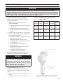
Series 16H
Gas-Fired Natural Draft Hot Water Boilers
INSTALLATION INSTRUCTIONS
Models:
• 16H-340
• 16H-410
• 16H-460
• 16H-505
WARNING: Improper installation,
adjustment, alteration, service or
maintenance can cause property
damage, injury, or loss of life.
For assistance or additional
installer, service agency or
the gas supplier. Read these
instructions carefully before
installing.
Manufacturer of Hydronic Heating Products
P.O. Box 14818 3633 I. Street
Philadelphia, PA 19134
www.crownboiler.com
3050579
1
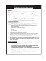
IMPORTANT INFORMATION - READ CAREFULLY
!"
#
"
$%"
&'
The following terms are used throughout this manual to bring attention to the presence of
hazards of various risk levels, or to important information concerning product life.
DANGER
CAUTION
Indicates an imminently hazardous situation
which, if not avoided, will result in death, serious
injury or substantial property damage.
Indicates a potentially hazardous situation which,
if not avoided, may result in moderate or minor
injury or property damage.
WARNING
NOTICE
Indicates a potentially hazardous situation which,
if not avoided, could result in death, serious injury
or substantial property damage.
Indicates special instructions on installation,
operation, or maintenance which are important
but not related to personal injury hazards.
DANGER
appliance.
If you smell gas vapors, DO NOT try to operate any appliance - DO NOT touch any electrical switch or use
any phone in the building. Immediately, call the gas supplier from a remotely located phone. Follow the
!
"
nor on concrete over any heat affected material such as plastic piping or wiring without a properly in
!
NOTICE
All Series 16H cast iron boilers are designed, built, marked and tested in accordance with the ASME Boiler
and Pressure Vessel Code, Section IV, Heating Boilers. An ASME Data Label is factory applied to each 16H
jacket, which indicates the boiler Maximum Allowable working Pressure (MAWP). Each cast iron section is
permanently marked with the MAWP listed on the boiler’s ASME Data Label. The MAWP for all Series 16H
Boilers is 50 psi (Water Only).
It is common and acceptable practice to install these boilers in lower pressure systems, below the boiler
MAWP. Therefore, in addition to Safety Relief Valves set for 50 psi, Crown also offers Safety Relief Valves set
for 30 psi (By Special Order Only).
2
WARNING
!#"
in this manual.
Improper installation, adjustment, alteration, service or maintenance can cause property damage, personal
injury or loss of life. Read and understand the entire manual before attempting installation, start-up
operation, or service. Installation and service must be performed only by an knowledgeable, experienced,
and skilled installer or service agency.
This boiler must be properly vented.
combustion and ventilation air.
The interior of the venting system must be inspected and cleaned before the start of the heating season
and should be inspected periodically throughout the heating season for any obstructions. A clean and
unobstructed venting system is necessary to allow noxious fumes that could cause injury or loss of life
"
"
!
Installation is not complete unless a pressure relief valve is installed into the tapping located on the top
of boiler - See the Water Trim and Piping Section of this manual for details.
This boiler is supplied with safety devices which may cause the boiler to shut down and not re-start
without service. If damage due to frozen pipes is a possibility, the heating system should not be left
unattended in cold weather; or appropriate safeguards and alarms should be installed on the heating
system to prevent damage if the boiler is inoperative.
"
!
"
to disconnect any components of this boiler without positively assuring the water is cool and has no
!$""
"
boiler to prevent scald injuries. Do not rely on the pressure and temperature gauges to determine the
temperature and pressure of the boiler.
This boiler contains components which become very hot when the boiler is operating. Do not touch any
components unless they are cool.
Boiler materials of construction, products of combustion and the fuel contain alumina, silica, heavy metals,
carbon monoxide, nitrogen oxides, aldehydes and/or other toxic or harmful substances which can cause
death or serious injury and which are known to the state of California to cause cancer, birth defects and
!$"
"
or working nearby the appliance.
Failure to follow all instructions in the proper order can cause personal injury or death. Read all instructions,
including all those contained in component manufacturers manuals which are provided with the boiler
before installing, starting up, operating, maintaining or servicing.
% !
Do not operate boiler with control which has been subject to water.
All cover plates, enclosures and guards must be in place at all times.
NOTICE
This boiler has a limited warranty. It is the responsibility of the installing contractor to see that all
controls are correctly installed and are operating properly when the installation is complete.
USA boilers built for installation at altitudes greater than 2,000 feet above sea level have been specially
&
'***
#+4
#7$8&9$:<=>>?!':@!'!>$J#!
3
Table of Contents
( )
*(6
(( +
"!8
((( -&
%!"!15
(/ 0
)19
/ -)23
/( /25
/(( 28
/((( %!%
*36
&
(7 %
#:
42
7 ;
)
49
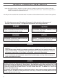
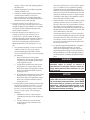
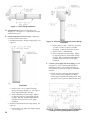
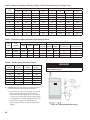
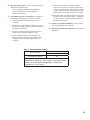
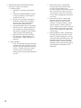
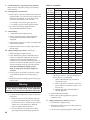
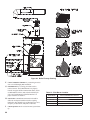
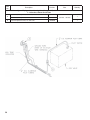
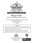
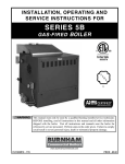
Figure 1: Dimensional Data
Table 1: Dimensional Data
Dimensions (Inches)
Boiler
Model
Recommended
Chimney Size
(Round)
Water
Content
(Gallons)
Approx.
Shipping
Weight (LB.)
A
B
C
D
E
Knockdown
16H-340
27-1/2
13-3/4
8
27-13/16
18
8” dia. x 15 ft.
15.9
870
16H-410
31-1/4
15-5/8
9
30-13/16
20
8” dia. x 15 ft.
17.9
955
16H-460
35
17-1/2
10
33-1/2
22
10” dia. x 15 ft.
19.9
1050
16H-505
38-3/4
19-3/8
10
33-1/2
22
10” dia. x 15 ft.
21.9
1150
5
I. Pre-Installation
WARNING
K N@R*GNC*N@R*FCF
W
Carefully read all instructions before installing
boiler. Failure to follow all instructions in proper
order can cause personal injury or death.
E
NTU
FNXU
Q
<
<<V
@U
A Inspect shipment
!
!
"
!
<
=
!#
!
"!
!
!
#
!+
>
<
!?@CD!
D. Provide clearance for servicing
?
!
#D
N %
<N@R*LGC<E
KGU?@NCD
K %
<N@R*GNC*N@R*FCF<E
GTU
?NKKCD
L >'
<%NU?KFD
E. !
E
#
!
V
#
!
V
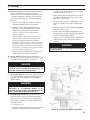
B. Installation must conform to the requirements of
!#
(
<
National Fuel Gas Code<E)"FG'"%(JKKLN
0
!
!#
<
Standard for Controls
and Safety Devices for Automatically Fired Boilers<
"%('"%>&%Q*N
C. Provide clearance between combustible material
F. Protect gas ignition system components from
?
<
!<
<D
#?
<
<D
G. Provide combustion and ventilation air
=?
D
#<
the National Fuel Gas Code<E)"FG'"%(JKKLN<
"
&/
NN@R*LGC
"#
E
NTU
L@U
Q
<
<V
@U
WARNING
$
provided to assure proper combustion.
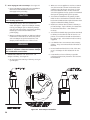
WARNING
$ ! #
" special base listed in Table 2. Boiler must not be
installed on carpeting. When boiler is installed on
concrete which is over a material that is subject
to melting (PVC, PEX radiant tubing, etc.), the
special base must be used. A concrete pad is not
!
>Q:YZ
<
Combustible Flooring
Boiler Model
Special Base Part Number
16H-340
61816075
16H-410
61816085
16H-460
61816095
16H-505
61816105
National Fuel
Gas Code<E)"FG'"%(JKKLN
N Q
#?
D;
!?
D
/Y3Z[\YZ0YZRYZ
K Q
(
;
N<CCC+
?+D
L Q
!Q#/!
(
(
FC3 per
N<CCC+<
space
(
FC3
N<CCC+<
G Q
!"unusually
tight construction
0
#
#
6
N
=
<
0
*
<
&=
<
V
<*<
<
<
F E
building of other than unusually tight construction<
#
!
#!
=
@ E
building of unusually tight construction or in
a <
#
?D
!
!
?
D
!
>
?DLU?]@
D
\
NK?LCFD
\
NK
?LCFD%W
i. Q
>
N
G<CCC+
ii. /
>
N
G<CCC
+
Q
*
iii. R
W>
N
K<CCC
+
Q
*
NU?KFD
@U?NFKD
\NK
?LCFD%W
i. Minimum free area of 1 square inch per
L<CCC+
ii. E
#
space.$
!?D
##
%W
N
N<CCC+
<
NCC
] /Q\#
-
#
#
<
#
\#
=
!
%
^
&
=#
<
W
#
(
#
=<#
#KC*KF
#
#
@C*]F
T E
%!
(#
#
<
#!
!
#
<
#!
<#<V
WARNING
Do not install boiler where gasoline or other
hydrocarbons (i.e. bleaches, cleaners, chemicals,
sprays, paint removers, fabric softeners, etc.) are
used or stored.
NOTICE
Mis-sizing of the boiler with regard to the heating
system load will result in excessive boiler cycling
and accelerated component failure. Crown DOES
NOT warrant failures caused by mis-sized boiler
applications. DO NOT oversize the boiler to the
system. Modular/multiple boilers greatly reduce
the likelihood of boiler oversizing.
7
II. Boiler Assembly
A. Remove Crate
N ;#
=
K \
#
#
B. Remove boiler from skid.%E
K
#
N )
;
%()
*(;#
K $
!
+)<
NXU=
(_U
+
=
L ;#NXU=)LU
V
=
G ;
=>#=!
F ;
LU
$
!
=
;#LU
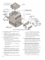
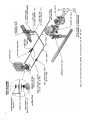
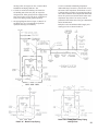
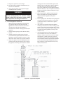
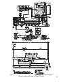
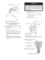
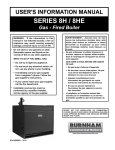
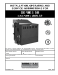
Figure 2: Skid Removal
Figure 3: Tapping Locations
Table 3: Purpose of Tappings
@
Tapping
Size
Purpose
A
2”
Supply
B
2”
Return
C
3/4”
Relief Valve
D
3/4”
Limit
E
3/4”
Auxiliary Limit
F
3/4”
Washout
G
3/4”
Drain
@ \
!
;#=
\
D. Test Section Assembly for leaks !
<
=;
E
LL
N )&:?_)D;
+?K)D
K (
_U)^U)Q
(
FC
L (
KU)_U)%!
"(
##
G &##Q
-
WARNING
Do not use air to leak test boiler.
F E
!
!#
##&
##!
NCFC
@ =
] ;#
;
+<&<
?
D"
###<
##<
E. Install special base V
%E
GE
G_U
N )V
=`E;U
K \
E
G
L )
+
=+
=#
G Q
?D
>N@R*LGC!
?#D
E
G
#
&Q<:Y
4#
9
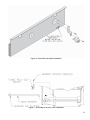
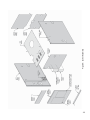
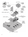
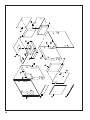
Figure 5: General Assembly (Knockdown Boilers)
F. Move boiler to permanent location!
=Q
G. positioned in each Boiler Flueway. Tabs at the top
E+V
E
)
H. Install Canopy!%E
F
&!
&
+
)
&
&
N )&!%"!\
=
K E^U*KCNU
<
L %&!%"!
I. Inspect joints between sections.!
!
(!
<
&
!
J. Install Base Front Panel.%E
F)
&+
)
&
&
N "+E
)%"!
10
^U*KCN^U
<
K %+E
)%
"!
?
&+
)
&
&
D
L %+;
)%
"!
K. Install Pilot/Main Burner Assembly. %E
]
"!&+
)
&
&
/
!!
!
=+;
)<>
+
<
L. Adjust Burner Air Shutters on all Burners.%
E
]Q
+
"
%
!NN'N@U<
?;+
"
)?DE
Q
)=+
D
M. Attach Flame Roll-out Switch+
")
%E
@E;*%
&+
)
&
&
E;*%#
**
N &
Figure 6: Flame Roll-out Switch Installation
Figure 7: Burner/Burner Access Panel Installation
11
>N@R*GNC*
N@R*FCF#?KD
;#
!
K "E;*%>+
=
?NDkTXU
L "E;*%
=
?NDkT_U
N. !\+
"
)?D&+
)
&
&
+
")
+E
)%E
F
O. "!
N ;#(
0?D
&
+
)
&
&
K (
(
0Q%E
L
L (
<
(#
=<
!
P. Install Jacket. %E
T
N \
?GDv="+
=
&+
)
&
&
"E
+);
+)
kT
%E
F
K R\%);%)
v="+
=
L "\
;
)\;%
)Q
G "$
;
)\
;
)Q
?LD
F ;#;\
#
=
`;"(-\"+\&\%QU;#
&&
\
&
+
)
&
&
"
/)
@ "/)\%;%
)
] "\
E
+
\%;
%)
T $
E
)\%
;%)))
12
")\%<;%$
;
)
z =
NC "\'
(
\
0
Q
\E
;#Q
\
&+
)
&
&
Q. Install Junction Box.%E
T"
\%)^U*KC^U
?&+
)
&
&
D
R. Install Limit Control.\&
+
)
&
&
(
S. Install Auxiliary Limit
?D
(
T. Install Gas Control Assembly.;
%(((<
-&
%!"!
U. EP-CSD-1 System: See Figure 9.
N (
*
)&
&"!
=
K (R!;>]TzC&
?
;>]TzC&
&
D
L ;#;>]TzC{Q&#
0
<
!
`v;KU
;Q
&#
G (R!;]TG]E"
F (
13
#
@Q^_$
Figure 9: EP-CSD-1 Control Installation
'&
III. Gas Control System Assembly (Knockdown Boilers)
A. #$
B. EP-CSD-1 Control System
Install Gas Control System."
&+
)
&
&
Install Gas Control System"
&+
)
&
&
N (-&
"!>%
E
NN$
?D?D
N (-&
"!>%
E
NF
K (
R!(
i. $%"*%E
NK
L ((>
"(&
>+
=
v=/)?KDkTXU
"R!(>>
+
=?KDkTXU
&
'
?D;
`%/((
U
K (
%E
NF
L ((
"(
v=/
)
?GDkTXU
&(\
)(
G >&
&
?
D
v+
"
'
G >
?
D
&
&
?
Dv
+%E
T
&!*GU!
'
"
'
#
'*Q
`q4
{|:}~Z
7
{
4<
15
16
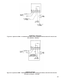
Figure 11: Main Gas Piping, Intermittent Ignition (EI)
17
Figure 12: Schematic Pilot Piping (Honeywell EI), USA
'@
#
'8Q:+774:'4
:'&'*'8*8
IV. Water Trim and Piping
WARNING
Failure to properly pipe boiler may result in improper operation and damage to boiler or structure.
Oxygen contamination of boiler water will cause corrosion of iron and steel boiler components, and can
lead to boiler failure. Crown’s Warranty does not cover problems caused by oxygen contamination of
"
|
"
!
A Design and install boiler and system piping to
#!
N !!
contamination such as:
"#=*
!=
"
=
!
!
K (
<!
!
=
;
!=
=*
=
!
'
!
$*
!
(
!
!
$
!
#
&Q#"Z
Z
Pressure Drop
Temp. Rise Min. Boiler
Thru Boiler Piping NPT
Boiler
Pressure
Drop
Boiler
Model
Flow Rate
(GPM)
16H-340
28
19
14
20° F
30° F
40° F
2”
1½”
1¼”
3’
2’
1’
16H-410
34
22
17
20° F
30° F
40° F
2”
1½”
1½”
3’
2’
1’
16H-460
38
25
19
20° F
30° F
40° F
2”
2”
1½”
3’
2’
1’
16H-505
42
28
21
20° F
30° F
40° F
2”
2”
1½”
3’
2’
1’
B. %$
$&
'to obtain proper
?%GD
WARNING
Pressure relief valve discharge piping must be
piped such that the potential of severe burns
is eliminated. DO NOT pipe in any area where
freezing could occur. DO NOT install any shut off
valves, plugs or caps. Consult Local Codes for
proper discharge piping arrangement.
C. Install Safety Relief Valve.%E
N@
&
0
&
%!
;/##
N (_U)LXU`&U%
E
L
K (!
##_U)
Figure 16: Safety Relief Valve Installation
19
Figure 17: Drain Piping Installation
D. Install Drain Valve
\%<
`-U%E
N]&
0
&
E. Install Temperature-Pressure Gauge.&
0
&
N %
*)
-)%
E
NT
Figure 19: Alternate Temperature-Pressure Gauge
Installation
(K)_)K)?
#D
K)K)_)?
D_)
(_)^)+
(
*)
-
!!
==
Q"))\});%%$;
-"$-&"%!
F. Connect system supply and return piping
%E
KN"<([+[;(
)-KFC>X
N (
!<
##
#
#
'@Q
7
+
Installation
(KU)NCU
%!`"U%E
L
-
(
*)
-
!!
==
Q"))\});%%$;
-"$-&"%!
K "
*)
-)%
E
Nz
(K)NCU%!
`"U%E
L
20
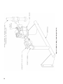
Figure 20: Recommended Piping for Combination
Heating & Cooling (Refrigeration) System
%E
KC"<([+[;
()-KFC
K (
!!
<
V
##
#
#!
!
L ?E
KN<Q`"U
Q`+UD
!
&
?
D
!GC~E
<
NLF~E
&
!GC~E'
!NLF~E<!
V
'
=
)V
!
W
G
#
>'QZY
7
4
=:
Detail “A”: Blend Pump Piping
Detail “B”: Primary/Secondary Piping
with By-Pass
21
"
!*
!
#!
<
#
!*
#
!
V
%E
KN
"
#
!
!
!NLF~E
{
!GC~E
W
%E
KN<Q`"U
)
!'
!!*
#
!
?
<
<!
=
W
=D%E
KN<
Q`+U
(!
*!##
<
!
!
NLF~E
?
=<!
D<
!'
!
*
!##
G "
#
#
#
#
F "
*
?
=D
#
!
!
#!
=
#
G. Water Heater?D;
>*%
(
(
(
W
WARNING
4
"
|
&*
#
"
'?8
#!
Continued boiler operation for prolonged periods of time under conditions when temperature differential
J&*
#9
"
"'?8
#
9
_!
<J
9
shock, the above-recommended temperatures may be maintained by employing common industry-accepted
mixing methods to provide boiler protection.
Some common methods are boiler by-pass piping, blend pumps, primary secondary piping with a bypass, mixing valves and/or variable speed injection pumps.
Z
Z
Q@!?'*!8
TDS: < 3500 ppm
Total alkalinity ppm as CaCO3 : < 1200
Total copper ppm: < .05
Oily matter ppm: < -1
Total harness ppm: < -3
Chlorides: < 50 ppm
22
V. Gas Piping
G %
#!-!
#!C]C
W
!
@<
!#
#!
E
#!
C]C<!
#!
T(
#!
#
E
#<
National Fuel Gas Code<E)"
FG'"%(JKKLN<
W!
!#
WARNING
Failure to properly pipe gas supply to boiler may
result in improper operation and damage to the
boiler or structure. Always assure gas piping is
absolutely leak free and of the proper size and
type for the connected load.
An additional gas pressure regulator may be
needed. Consult gas supplier.
A. Size gas Piping.Q!
#
!
&
N "
#
!
>!
X
"#
!
!
>##
K >F
"
W?
<=
D
L \
;
@
!%GC
]#
WARNING
Failure to use proper thread compounds on all
_
gas.
WARNING
Gas supply to boiler and system must be
absolutely shut off prior to installing or servicing
boiler gas piping.
B. Connect boiler gas valve!!
N $
(
<National
Fuel Gas Code<E)"FG'"%(JKKLN
Table 5: Rated Input
Boiler
Model
16H-340
Rated Capacity
(cubic feet per hour)
Natural
LP / Propane
Gas
Connection
Size
340
136.0
1
16H-410
410
164.0
1
16H-460
460
184.0
1
16H-505
505
202.0
1
K $
?D?D
L (
<
*
*##
##
=%E
KK
G "#
##
!
Q
;
National Electrical Code<"%('E)"]C'
&%"&KKN
&
NOTICE
Y
>***
&
'***
#+4#7$8&9$:<
=>>?!':@!'!>$J#!
23
QqJ4:&*74#
+7
*!8
{
Length
(Feet)
½
0.3 Inch w.c. Pressure Drop
¾
1
1¼
½
0.5 Inch w.c. Pressure Drop
¾
1
1¼
10
132
278
520
1,050
175
360
680
1,400
20
92
190
350
730
120
250
465
950
30
73
152
285
590
97
200
375
770
40
63
130
245
500
82
170
320
660
50
56
115
215
440
73
151
285
580
60
50
105
195
400
66
138
260
530
70
46
96
180
370
61
125
240
490
80
43
90
170
350
57
118
220
460
90
40
84
160
320
53
110
205
430
100
38
79
150
305
50
103
195
400
~Q{:
7#`
Pipe
Size
I.D.
(Inches)
Valves (Fully Open)
Gate
Globe
Angle
Threaded Fittings
Swing
Check
90°
Elbow
45°
Elbow
90° Tee, Flow
Through Run
90° Tee, Flow
Through Branch
½”
0.622
0.35
18.6
9.3
4.3
1.6
0.78
1.0
3.1
¾”
0.824
0.44
23.1
11.5
5.3
2.1
0.97
1.4
4.1
1”
1.049
0.56
29.4
14.7
6.8
2.6
1.23
1.8
5.3
1¼”
1.380
0.74
38.6
19.3
8.9
3.5
1.6
2.3
6.9
@Q:+
4
#
Gravity
Correction
Factor
Gravity
Correction
Factor
0.50
1.10
1.30
1.07
0.55
1.04
1.40
1.04
0.60
1.00
1.50
1.00
0.65
0.96
1.60
0.97
0.70
0.93
1.70
0.94
0.75
0.90
---
---
0.80
0.87
---
---
WARNING
other ignition source.
C. Pressure Test.
=
N)
##E
#
X<
#*##
!E
X
<
!
!
{#*##
K \=
#
<
<
V
>&
Figure 22: Recommended Gas Piping
VI. Venting
A. Install vent system
!#
National Fuel Gas Code<"%(JKKLN'E)"FG<)
]</(!
%
N@R&
!(<
N !+
!\#(
{
D
Q
R=
%E
KL
L %
=
Q
R=
)kNC
#=
{
G %
=!kNC
Q
R
=
K >
!
!+
!#
Standard for
Chimneys, Fireplaces, Vents, and Solid Fuel
Burning Appliances.
F (
v=;%
);#=
] /
!
<
=<+=
/%
E
KL
>
!!
#
!V
!!
#"%(JKKLN'E)"FG<
)
]FG?DException: Where permitted by
the authority having jurisdiction, existing chimneys
shall be permitted to have their use continued when
an appliance is replaced by an appliance of similar
@ )
){#
=
v=;%)
WARNING
Do not operate boiler without Blocked Vent Switch
Properly installed.
L %#"!"%(JKKLN'
E)"FG
#
!
#
B. Inspect chimney
#!
&!
#!
*
DANGER
Inspect existing chimney before installing boiler.
Failure to clean or replace perforated pipe or tile
lining will cause severe injury or death.
C. Install Draft Hood!>
v=)Q
R=
E
NQ"\;<&$<;>Q(E}
Q;"ERQ
WARNING
Do not alter boiler draft hood or place any
obstruction or non-approved damper in the
breeching or vent system. Flue gas spillage can
occur. Unsafe boiler operation will occur.
D. Install Blocked Vent Switch.+=/
%"!
<
<
=
!&+
)
&
&
N $
K )
=
Q
R=
\
?kNC
Figure 23: Blocked Vent Switch Installation
25
E. Boiler Equipped With Vent Damper.%E
KG
N /Q
&
#(
(
;((
!
CAUTION
Do not use one vent damper to control two or
more heating appliances.
K /
W
%E
N$=#
!
E
#
!
#
!/
!
*
W
L >#
!
?;
=
#
D/
#
K 0
#
#<
#
#FC
#Q
#!
!
#
L /
#
#
#
G (#
#!
#=*!
#*!
!
F /
!
#
#
/
!
@ $
#
!
!*=#
V
V
WARNING
7
provide 6” minimum clearance between damper
and combustible construction.
F. Install Vent Connector
#
!%E
KF
N Q!
#
] Q*?"-"<&-"<&%"<\<
$\D#
#
T \+
&!
!
%%(
)
*(
#
>&Q
<
26
z Q#!
#
NC )
##+
;%
%()
*(
NN #
!
#!
WARNING
When an existing boiler is removed from a
common venting system, the common venting
system is likely to be too large for proper venting
of the appliances remaining connected to it.
G. If an Existing Boiler is Removed:
0
#
<
#!<
#!
operation:
N %!#
!
K /!#!
W
W
=
<=<
<
L (
<
#!
!
!
#!
!<
*
<!
Q
&
G )
E\?
D(
"
!
F F
$V
<
=
<
@ "
#!
!##<
<<<
!
*
#
] "!
#
!
National Fuel Gas Code<E)"
FG'"%(JKKLN0
W!
#!<#
!
W
W
)
])
NNNational Fuel Gas Code<
E)"FG'"%(JKKLN
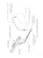
Figure 25: Typical Vent System
27
VII. Electrical
DANGER
Positively assure all electrical connections are unpowered before attempting installation or service of
electrical components or connections of the boiler or building. Lock out all electrical boxes with padlock
once power is turned off.
WARNING
Failure to properly wire electrical connections to the boiler may result in serious physical harm.
Electrical power may be from more than one source. Make sure all power is off before attempting any
electrical work.
Each boiler must be protected with a properly sized fused disconnect.
Never jump out or make inoperative any safety or operating controls.
The wiring diagrams contained in this manual are for reference purposes only. Each boiler is shipped with
a wiring diagram attached to the front door. Refer to this diagram and the wiring diagram of any controls
used with the boiler. Read, understand and follow all wiring instructions supplied with the controls.
A. Install Boiler Wiring
C. Install thermostat.\
N \
&+
)
&
&
;
NC
K &!
!
!#
<
National Electrical Code<"%('E)"]C
B. Wire Vent Damper?N@R*LGC
N@R*FCFD%E
KG
N "/Q
R
v=\%)(&&
Vv=)
!G#V
Q
<
<
V
!
V<
<
<#<
"
#!#
%
!
;
z
D. Wire thermostat.)
#&((
;
!
K ;#
!v
)
/
Q
;/0
R
L )/Q
R
)/Q
;%E
KG
#
>Q
:
|'?&*'8*8
>@
E. MegaStor Water Heater ?D>!
(
&
!
;
>%
(<
%
#(
<
F. Vent Damper Sequence of Operation.%E
K@
?N@R*LGC*N@R*FCFD
N /Q
!
N
K 0
<
!
W
F
L !
W
<
F 0
<
!*
W*
W
0
!
<
*
W
)0;E"(\$;*
?&
#
=
!D
G. Sequence of Operation and Wiring.;
NC
!
H. Optional Low-Water Cut-Off Wiring.%E
GK
GG
G 0
!
<
=
K
*
W
Table 9: Heat Anticipator Settings
Control System
24V Electronic Ignition
Heat Anticipator Setting*
Intermittent Circulation
0.3
* If room is heated above thermostat temperature setting, reduce
heat anticipator setting by 0.1 or 0.2 amps. If boiler short cycles
without room reaching desired temperature, increase heat
anticipator by 0.1 or 0.2 amps.
29
'*Q:
Ignition System
Country
Intermittent Ignition
(Honeywell EI - 24V)
USA
Intermittent Ignition
(EP-CSD-1 - 120V)
USA
Fuel
Intermittent
7 - 10 Sect.
Figure 31
Page 30
8 - 10 Sect.
Figure 35
Page 32
Natural Gas
LP Gas
Natural Gas
N R!(%
i. /Q
?D
ii. (>
)/<>/')/
(
W
)/>/')/
)
/#-/#!
)(
#(
=)
iii. &
LGTN+
)+
(-((>Q$\
#
)E
!(
*
W
iv. >/>/')/
(-((>Q$\
W
!
>-/#
-/#
W
V<>+
v. &
(*
W<*
W##<
V/
Q
?D
%!%
i. \"!
(>-/#?D<
V<
>
KFC~E
&
</Q
?D
ii. +=/%"!
#V
30
Wiring Diagram Figure
Sequence of
Operation
Boiler Sizes
&
/
Q
?D
(=##
&
=
#
iii. E;*"!
V
#
#&
<
/Q
?D
&
#
(V
*#<
&
V
*
iv. )
)
*
!
"!
LGTN+
)<
V
##CT
E
!zC
LGTN+<
!
V(V
!V
<
)/
>/')/
*
W
=!E#
<(-((>Q$\
<<
?
D
!
%-%)GT
MegaStor
Relay
MegaStor
#
?'Q
"<:$<
4
|'?&*'8'*
31
K !%
#(
(
?)*&%Q*ND%
i. ii. k@;>]TzC"+
&
W<
iii. ##?
TD
?
NCD
W
##
=<
iv. "
V
#<
?NCD*
W
##
?zD
W<
V
`>U
v. 0
<
k@
*
W<
V`>U*
W
%!%
i. \"!
>
KFC~E&
32
ii. +=/%"!
#V
&
(=##<
&
=
#
iii. E;*%"!
V
#
#&
&
#(V
*#<
&
V
*
iv. ;>]TzC"+
&
"!
V
V
;>]TzC"=
!
`"
U
;
;>]TzC"
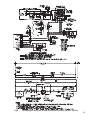
Figure 35: Wiring Diagram, EP Ignition System, Natural Gas Only, Intermittent Circulation
|74:'
+:$'&'*'8*8
33
#
?Qq`q
~8'7q|'>*{!!4!!
Y
">&{4
|<|'?&*'8*8
?&
Figure 37: McDonnell & Miller 751P-MT (120V) L.W.C.O. Wiring for Boilers with 120V Limit Circuits
|74:'|'&'*'8*8
#
?@Q
q'~*988*98*9~8*|'>*{!!4!!
Y
">&{4
|<|'?&*'8*8
Figure 39: Hydrolevel OEM - 170/550/650/750 (120V) L.W.C.O. Wiring for Boilers with 120V Limit Circuits
|74:'|'&'*'8*8
35
VIII. System Start-Up
WARNING
Completely read, understand and follow all
instructions in this manual before attempting
start-up.
A. Safe operation
!
#
American National Standard for Gas-Fired LowPressure Steam and Hot Water Boilers<"%(JKNNL
B. Check Main Burners.>
!
=+;
)<
>+
<
C. Verify that the venting, water piping, gas piping
and electrical system
!;
D. ('&$
#
E. FILL ENTIRE HEATING SYSTEM WITH WATER
#
!$
%
\
*W!
E
KN
#
!
WARNING
The maximum operating pressure of this boiler is
50 psig. Never exceed this pressure. Do not plug
or modify pressure relief valve.
N &
##
!
K (W!W##
*
##!
W?D
L "#
##
##!!
?*
#=
V
D
z &
##<!
&##
?*(=*
##<
##
E##
{
D
NC ##
!
NN ;#
##
F. &
'
leaks.
G. Prepare to check operation.
N #?+
D
K &
##
$N'T)
#
L !
*
G !
F &
!
##
NG
@ *##
##
] $<
*
<
=
#
&=
<##<
=
!
=
T )
H. Follow Lighting or Operating Instructions
;
E
;#)
E
NN
DANGER
other ignition source to check for leaks.
G %
<W##
*##!!
F ##
@ ##?>=*
!
##!
!
=D
] "
#
V
=
LC
T &W##
*##
W
<W##
*##
W
;W#
"
<W##
*##
36
Table 11: Lighting and Operating Instructions
Ignition System
Lighting and
Operating
Instructions
Pilot Flame
Illustration
Honeywell EI
Figure 41
Figure 45
EP-CSD-1
Figure 43
Figure 46
#
&'Q
<
|<
37
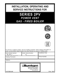
FOR YOUR SAFETY READ BEFORE OPERATING
WARNING: If you do not follow these instructions exactly, a fire or explosion may result
causing property damage, personal injury, or loss of life.
A. This appliance is equipped with an ignition device
which automatically lights the pilot. Do not try to light
the pilot by hand.
B. BEFORE OPERATING smell all around the appliance area
for gas. Be sure to smell next to the floor because some
gas is heavier than air and will settle on the floor.
WHAT TO DO IF YOU SMELL GAS:
Do not try to light any appliance.
Do not touch any electric switch; do not use any
phone in your building.
Immediately call your gas supplier from a neighbor's
phone. Follow the gas supplier's instructions.
If you cannot reach your gas supplier, call the
fire department.
C. Use only your hand to push in or turn the gas control
knob. Never use tools. If the knob will not push in or
turn by hand, don't try to repair it, call a qualified
service technician. Force or attempted repair may
result in a fire or explosion.
D. Do not use this appliance if any part has been under
water. Immediately call a qualified service technician
to inspect the appliance and to replace any part of the
control system and any gas control which has been
under water.
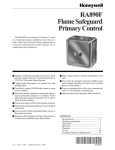
OPERATING INSTRUCTIONS
1. STOP! Read the safety information above on this label.
2. Set the thermostat to lowest setting.
3. Turn off all electric power to the appliance.
RESET SAFETY
SWITCH BUTTON
POSITION
INDICATOR
ON
RM7890A
ELECTRONIC
CONTROL
PANEL
MAIN POWER
ROCKER
SWITCH
MAIN GAS ROCKER
SWITCH
CONTROL LOCATION DIAGRAM
4. EP SYSTEM: Flip both rocker switches to "O" position (off).
5. This appliance is equipped with an ignition device
which automatically lights the pilot. Do not try to light
the pilot by hand.
6. Remove front door.
7. Open manual pilot valve (CSD-1 Boilers Only).
8. Locate the gas control valve at the end of the gas
supply pipe going into the boiler. The gas control knob
is the knob located on top of the gas valve (see diagram
to right).
9. Rotate gas control knob clockwise
from "ON"
position to "OFF". Make sure knob rests against stop.
10. Wait five (5) minutes to clear out any gas. Then smell
for gas, including near the floor. If you smell gas,
STOP! Follow "B" in the safety information above on
this label. If you do not smell gas, go to the next step.
OFF
PILOT
GAS
INLET
GAS CONTROL KNOB
SHOWN IN "OFF" POSITION
11. Turn gas control knob counterclockwise
from
"OFF" to "PILOT". When the proper position is reached
the gas control knob will pop up.
12. Turn on all electric power to the appliance.
13. Set the thermostat or operating control to desired
setting.
14. EP SYSTEM
See control location diagram. On the electronic control
panel, flip the main power rocker switch to "l" position
(on). The "POWER" status indicator will light.
The pilot will light electronically. If pilot failure occurs,
the "ALARM" indicator will light. In case of pilot
failure, proceed to step 11.
Turn gas control knob counterclockwise
to "ON".
On the electronic control panel, flip the main gas valve
rocker switch to "l" position (on). The "MAIN" gas valve
indicator will light. Main burners will operate.
"MAIN" gas valve indicator will cycle on and off at the
same time as the thermostat or operating control and
the main burners.
15. Replace front door.
16. If the appliance will not operate, follow the instructions
"TO TURN OFF GAS TO APPLIANCE" and call your
service technician or gas supplier.
TO TURN OFF GAS TO APPLIANCE
1. Set the thermostat to the lowest setting.
2. Turn off all electric power to the appliance if service is
to be performed.
3. Remove front door.
4. Rotate gas control knob clockwise
from "ON"
position to "OFF". Make sure knob rests against stop.
5. Close manual pilot valve (CSD-1 Boilers Only).
6. Replace front door.
81460284R4
#
&?Q
<
|74:'
?@
CAUTION
Avoid operating this boiler in an environment
"
"
"
dust, etc. are present. If boiler is operated under
these conditions, the burner interior and ports
must be cleaned and inspected daily to insure
proper operation.
\=
&
!
V
%!
!
#
=
G "
#
&8Q"?&@'Y7#
|>&
<
I. )
&
#
N &=V;
NN
K "
L &=
V%E
G]E
#
!
!
*!
=
!
!
}*=
!
(
>+
!
"
!
#
&Q"'~47#|7
#
&~QqY
#
39
J. Check thermostat or operating control operation
;
K. Check ignition system shut-off.
N R!(Q
'
-##
(<
#
##
`RU`;U
(#
<
##
(#
<
K );
R!;>]TzC+
&
L. )*!
N "
K #
0
L "#
#
>
G "
"
M. Adjust gas input rate to boiler
-
N "
K &=
>
"##
!?
=
<
=
D(
<=##
If less than minimum gas supply pressure
listed on rating label, contact gas supplier for
assistance
L &=
LC$
NK
V
&E
R
G Q
(;>!V
!
#
Warning
Failure to properly adjust gas input rate will result
!
Improper and unsafe boiler operation may result.
F &
+
#
;
!
Q
CL(
#
<
!
&
;
-
(
zT
(
&*
Table 12: Input Rate
Size of Gas Meter Dial
Seconds
for One
One-Half
One
Two
Five
Revolution Cu. Ft.
Cu. Ft.
Cu. Ft.
Cu. Ft.
30
60
120
240
600
32
34
56
113
225
563
53
106
212
529
36
50
100
200
500
40
45
90
180
450
38
47
95
189
474
40
45
90
180
450
42
43
86
172
430
44
41
82
164
410
46
39
78
157
391
48
37
75
150
375
50
36
72
144
360
52
35
69
138
346
54
33
67
133
333
56
32
64
129
321
58
31
62
124
310
60
30
60
120
300
62
29
58
116
290
64
29
56
112
281
66
29
54
109
273
68
28
53
106
265
70
26
51
103
257
72
25
50
100
250
74
24
48
97
243
76
24
47
95
237
78
23
46
92
231
80
22
45
90
225
CL(
zT
i. ;#>+
%(7%
#
ii. ;#
Q
?ND
W
?
W
<
!GD
iii. ;
>
@ ;=>+
E
] ;
*
#
N. Adjust gas input rate to boiler.\)')
N %
K "=
##
NLF
L -##
!
NG
KF
!LC&=
"
##
!
NCC
?
=
<
=
D(NCC
<=##
(
NNC<
O. Clean Heating System
<
<
=!<
!V"
#
P. Check Damper Operation*(
#
<#
%
<
Q. Install Front Removable Panel.
N V?
KVD
$
E
)
K %
L \
V\
E
+
R. Combustion Chamber Burn-Off
N #
K /
<
<
L "
G ;
S. Review User’s Information Manual!
&'
IX. Service
WARNING
:
_
_
!<
!q
legible condition.
% !
"
"
!
The service instructions contained in this manual are in addition to the instructions provided by the
manufacturer of the boiler components. Follow component manufacturer’s instructions. Component
manufacturer’s instructions were provided with the boiler. Contact component manufacturer for replacement if instructions are missing. Do not install, start up, operate, maintain or service this boiler without
reading and understanding all of the component instructions. Do not allow the boiler to operate with
altered, disconnected or jumpered components. Only use replacement components identical to those
originally supplied by Crown Boiler Company.
A. General. (
#
!
!
#
E
$;EE-"%"))\("&%\'
(
E
;#
Q
WARNING
Label all wires prior to disconnection when
servicing controls. Wiring errors can cause
improper and dangerous operation. Verify proper
operation after servicing.
G ;#
?D
F >
=>+
)+
=
@ ;#
>+
] R>+
\!
)
>+
\
T &=
!
&
<!
#
%E
GT
E. Clean Boiler Flueways. %E
GT
B. +
*
'"2
&!E
#
C. Vent System.&=
N K Q#!;#Q
R
K L ;#v=)
L #
#
G ;#&!
G <
!
W
runs
F ;#VV;
E
GT
#V
V!;#!
F ;#
#
@ !V!V
<
#%E
GT
;#
;
!%
] &
D. Remove Main Burners
<
<
N %
\'
(
E
;#
Q
&>%*/#
K ;#E
;#Q
;\
E
+
L Q!
&>
N %
\'
(
E
;#
Q
&>%*/#
T ;
VV!!
#
#E
GTV
V
z (&!%%((+
"!<
)
-
NC (v=)<Q
R</Q
?D/%!
Important Product Safety Information
Refractory Ceramic Fiber Product
Warning:
The Repair Parts list designates parts that contain refractory ceramic fibers
(RCF). RCF has been classified as a possible human carcinogen. When
exposed to temperatures above 1805°F, such as during direct flame contact,
RCF changes into crystalline silica, a known carcinogen. When disturbed as a
result of servicing or repair, these substances become airborne and, if inhaled,
may be hazardous to your health.
AVOID Breathing Fiber Particulates and Dust
Precautionary Measures:
Do not remove or replace RCF parts or attempt any service or repair work
involving RCF without wearing the following protective gear:
1. A National Institute for Occupational Safety and Health (NIOSH)
approved respirator
2. Long sleeved, loose fitting clothing
3. Gloves
4. Eye Protection
•
•
•
•
Take steps to assure adequate ventilation.
Wash all exposed body areas gently with soap and water after contact.
Wash work clothes separately from other laundry and rinse washing
machine after use to avoid contaminating other clothes.
Discard used RCF components by sealing in an airtight plastic bag. RCF
and crystalline silica are not classified as hazardous wastes in the United
States and Canada.
First Aid Procedures:
•
•
•
•
If contact with eyes: Flush with water for at least 15 minutes. Seek
immediate medical attention if irritation persists.
If contact with skin: Wash affected area gently with soap and water.
Seek immediate medical attention if irritation persists.
If breathing difficulty develops: Leave the area and move to a location
with clean fresh air. Seek immediate medical attention if breathing
difficulties persist.
Ingestion: Do not induce vomiting. Drink plenty of water. Seek
immediate medical attention.
&?
#
&@QY
#"4
F. Clean Combustion Chamber!#
#+(
G. Install Burners!
#
#
/
!>+
!
=+;
)<
>+
<
/
!>+
)+
=
%NL
H. Lubrication.>
(
!
<
!
<
I. Check operation.;
%/(((%!%
*
&&
Table 13: Pilot Burner Location
Boiler Model
Pilot Located Between Burners*
16H-340
6&7
16H-410
6&7
16H-460
7&8
16H-505
8&9
* Burners numbered left to right as viewed from front of boiler.
Honeywell EI Ignition Module Yellow LED Flame Codes
Yellow LED
Flash Codea
Indicates
Recommended Service Action
Heartbeat
Normal Flame Signal
N/A
2
Weak Flame Signal desired.
shortly after lightoff on some applications.
Perform routine maintenance to
1
Marginal Flame Signal (less than 1.1 μA) System may not operate reliably over time. Service call
recommended.
Note
shortly after lightoff on some applications.
#$
burner ground connection.
OFF
a
No Flame or Flame Signal below minimum threshold for system operation.
N/A
Flash Code Descriptions
- Heartbeat: Constant ½ second bright, ½ second dim cycles.
%+<=>?@J
sequence.
&8
Honeywell EI Ignition Module Green LED Status Codes
Green LED
Flash Code
Q>XZ[a
Next System Action
Recommended Service Action
No “Call for Heat”
N/A
None
Flash Fast
Startup - Flame sense
calibration
N/A
None
Heartbeat
Normal operation
N/A
None
OFF
If system fails to light on next trial for
ignition check gas supply, pilot burner,
$
contamination or out of position, burner
ground connection.
2
5 minute Retry Delay\
during trial for ignition
Initiate new trial for ignition after
retry delay completed.
3
Recycle- Flame failed
during run
If system fails to light on next trial
Initiate new trial for ignition. Flash
for ignition check gas supply, pilot
code will remain through the ignition
]
contamination, burner ground connection.
4
Flame sensed out of
sequence
If situation self corrects within 10
seconds, control returns to normal
^
remains longer than 10 seconds,
_`X{Q
below)
#$|]]
^
cycle “Call for Heat.” If error repeats,
replace control.
7
Flame sense leakage to
ground
Control remains in wait mode.
When the fault corrects, control
resumes normal operation after a
one minute delay.
#$
#$
#$
for cracks, damage or tracking.
8
Low secondary voltage
supply- (below 15.5 Vac)
Control remains in wait mode.
Check transformer and AC line for proper
When the fault corrects, control
input voltage to the control. Check with
resumes normal operation after one
full system load on the transformer.
minute delay.
`X?
5 minute Retry DelayOn every third retry on
same “Call for Heat”
Initiate new trial for ignition after
retry delay completed.
Check gas supply, pilot burner, spark
contamination or out of position, burner
ground connection.
`X}
~]`
failure during run on the
same “Call for Heat”
5 minute retry delay, then initiate
new trial for ignition.
#$
burner ground connection.
`X{
Flame sensed out of
sequence- longer than
10 seconds
#
longer sensed and then goes to
soft lockout. Flash code continues.
Control auto resets from soft
lockout after one hour.
#$|]]
^
cycle “Call for Heat.” If error repeats,
replace control.
Soft lockout due to error
detected during self
check sequences
Control auto resets from soft
lockout after one hour.
Reset by cycling “Call for Heat.” If error
repeats, replace the control
ON
a
Indicates
Flash Code Descriptions:
- Flash Fast: rapid blinking
- Heartbeat: Constant ½ second bright, ½ second dim cycles.
% +<=>?@J
repeats the sequence.
% >XZ+<=>?@J
Z
2 Hz, remains off for three seconds, and then repeats the sequence.
&
Honeywell EI Trouble Shooting Guide
&~
THIS PAGE LEFT BLANK INTENTIONALLY
&@
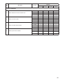
X. Repair Parts
"%
N@R;
)
!
!
&
%!
&
!
<
#
#!
&
<&
&
%
#
KNF*FLF*TzCC
E?KNFDFLF*z]L@
&
Item No.
Description
Part No.
Quantity
16H-340 16H-410 16H-460 16H-505
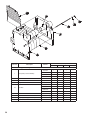
1. Heat Exchanger Assembly
1
1
---
---
---
6171608
---
1
---
---
6171609
---
---
1
---
6171610
---
---
---
1
1A
Left End Section
7171601
1
1
1
1
1B
Intermediate Section
7171603
5
6
7
8
1C
Right End Section
1D
50
#Q+_[
6171607
Tie Rod
7171602
1
1
1
1
80861013
1
---
---
---
80861034
---
1
---
---
80861035
---
---
1
---
80861036
---
---
---
1
1E
Washer
Procure Locally
4
4
4
4
1F
Nut
Procure Locally
4
4
4
4
1G
Slip Nipple, 3” (Upper & Lower)
7066002
12
14
16
18
1H
_
7111623
6
7
8
9
Item No.
Description
Part No.
Quantity
16H-340 16H-410 16H-460 16H-505
2. Canopy
2A
Canopy
61116071
1
---
---
---
260128
---
1
---
---
61116091
---
---
1
---
61116110
---
---
---
1
2B
Bolt, Carriage, ¼ - 20 x 1”
Procure Locally
2
2
2
2
2C
Washer, ¼” Flat
Procure Locally
2
2
2
2
2D
Nut, ¼” - 20
Procure Locally
2
2
2
2
51
Quantity
Item
No.
Description
Part No.
16H-340
16H-410
16H-460
16H-505
260660
2
2
2
2
260647
2
---
---
---
260648
---
2
---
---
260649
---
---
2
---
260650
---
---
---
2
260667
1
---
---
---
260668
---
1
---
---
260669
---
---
1
---
260670
---
---
---
1
260607
1
---
---
---
260608
---
1
---
---
260609
---
---
1
---
260610
---
---
---
1
260627
1
---
---
---
260628
---
2
---
---
260629
---
---
2
---
260630
---
---
---
2
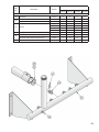
3. Base Assembly
3A
3B
3C
3D
3E
52
Base End Panel
Base Channel Assembly
Base Rear Panel Assembly
Base Front Panel Assembly
Burner Access Panel Assembly
3F
Jacket Attachment Bracket
7041601
4
4
4
4
3G
Bolt, Carriage, ¼ - 20 x 1¼”
Procure Locally
4
4
4
4
3H
Washer, ¼” Flat
Procure Locally
4
4
4
4
3J
Nut, ¼ - 20
Procure Locally
4
4
4
4
3K
Screw, Self Tapping, ¼ - 20 x ½”
Procure Locally
4
5
5
6
3L
Screw, Cap, Hex Head, 5/16” - 18 x ¾”
Procure Locally
2
2
2
2
3M
Screw, Cap, Hex Head, 5/16 - 18 x 1¼”
Procure Locally
6
6
6
6
3N
Screw, Sheet Metal, #8 x ½”
Procure Locally
8
8
8
8
3P
Washer, 3/8” Flat
Procure Locally
6
6
6
6
3Q
Nut, 5/16”
Procure Locally
6
6
6
6
3R
Screw, Self Tapping, ¼ - 20 x ¾”
Procure Locally
10
10
10
10
Item
No.
Description
Part No.
16H-340
16H-410
16H-460
16H-505
150161
12
15
17
19
Main burner with Pilot Bracket, Honeywell EI
150160
1
1
1
1
Main burner with Pilot Bracket, EP
8231603
1
1
1
1
260157
1
---
---
---
260158
---
1
---
---
260159
---
---
1
---
260160
---
---
---
1
---
1
1
1
1
~
{Q~[
950351
13
16
18
20
~
}Q+\\~[
950365
13
16
18
20
Hitch Pin Clip
950370
13
16
18
20
&!qqY
4A
4B
Main Burner
4C
Manifold
4D
Pipe Plug, 1/8 NPT (Included with 4C)
4E
4F
JQ%?[_@
53
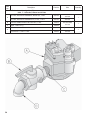
Item
No.
Description
Part No.
Size
Gas Valve, Robertshaw 7000DERHC, Natural Gas, 1” NPT
3507310
16H-340 THRU
16H-505
Gas Valve, Robertshaw 7000DERHC-LP, LP Gas, 1” NPT
3507315
16H-340 THRU
16H-505
B
Conbraco 50GB501A Manual Shut-Off Valve, 1” NPT
822615
C
Nipple, 1’ NPT x 2” Lg.
950102
16H-410 THRU
16H-505
Street Elbow, 1” NPT
950191
16H-340
Street Elbow, 1¼” NPT x 1” NPT
950193
16H-410 THRU
16H-505
Quantity
5-3 Gas Train -- Intermittent Ignition (EI)
USA: 7 - 10 Section, Natural and LP Gas
A
D
8&
1
1
1
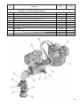
Item
No.
Description
Part No.
Quantity
8&+
<
<|74:'
:$Q@'*:
+
A
Gas Valve, Robertshaw 7000GVERHC-S7C, Natural Gas, 1” NPT
81660168
1
B
Solenoid Gas Valve, Honeywell V8295A1032, 1” NPT
81660236
1
C
Manual Shut-Off Valve, Conbraco #50-403-02, 1” NPT
822615
1
D
Leak Test/Shut-Off Valve, Conbraco #50GB501A, 1/8” x 1/8”
822679
2
E
Pipe Plug, 1/8”
Procure Locally
2
F
Hex Bushing, 1/4” x 1/8”
Procure Locally
1
G
Nipple, 1” x 2” Long
950102
2
H
Street Elbow, 90° x 1”
950191
1
J
Close Nipple, 1”
950110
1
K
Malleable Coupling, 1-1/4” x 1”
Procure Locally
1
L
Wiring Harness, Gas Valve to Solenoid Valve
6136230
1
M
Pilot Outlet Plug, Honeywell #394424
8226051
1
55
Item
No.
Description
Part No.
Size
Quantity
5-6 Pilot Assembly and Piping -- Intermittent Ignition (Honeywell EI) USA
7 - 10 Section, Natural and LP Gas
Pilot Burner, Honeywell Q3481B1206, Natural Gas
103704-01
Pilot Burner, Honeywell Q3481B1420, LP Gas
103705-01
A
B
56
1
Brass Compression Union, 1/4” OD Tube
8236008
16H-340 - 16H-505
1
Item
No.
Description
Part No.
Size
Quantity
5-9 Pilot Assembly and Piping -- Intermittent Ignition (EP-CSD-1)
:$Q@'*:
+
A
Pilot Burner, Honeywell Q179C1009, Natural Gas
8236017
1
B
Flame Rod Lead, Honeywell R1298020, 4 Ft. Lg.
71362561
1
C
Rajah Connector, Honeywell 37356
8236021
2
D
Ignition Lead, Honeywell R1061012, 3 Ft. Lg.
7136247
1
E
Ground Wire Assembly
6136259
1
F
Brass Compression Coupling, 1/4” OD Tube
8236008
1
G
Conbraco Leak Test / Shut-Off Cock, 1/8” x 1/8”
822679
H
Brass Compression Adapter, 1/4” OD Tube x 1/8” NPT
822630
J
Solenoid Gas Valve, Johnson H91WA-4
822662
1
K
Junction Box, 4” Sq. x 1-1/2” Deep
96-055
1
L
Rigid Conduit Nipple, 1/2” NPT x 1-1/2” Lg.
Procure Locally
1
M
Conduit Locknut, 1/2”
Procure Locally
2
N
Plastic Insulating Bushing, 1/2”
96-011
1
P
Regulator, Maxitrol RV12LT, Natural / LP Gas
8226005
1
1
16H-410 - 16H-505
2
57
8@
Item
No.
Description
Part No.
Quantity
16H-340
16H-410
16H-460
16H-505
60416131
1
---
---
---
60416141
---
1
---
---
60416151
---
---
1
---
60416161
---
---
---
1
704160793
1
---
---
---
704160893
---
1
---
---
704160993
---
---
1
---
704161093
---
---
---
1
7201611
1
---
---
---
7201613
---
1
---
---
7201615
---
---
1
---
7201617
---
---
---
1
704160795
1
---
---
---
704160895
---
1
---
---
704160995
---
---
1
---
704161095
---
---
---
1
72016079
1
---
---
---
72016089
---
1
---
---
72016099
---
---
1
---
72016109
---
---
---
1
60416079
1
---
---
---
60416089
---
1
---
---
60416099
---
---
1
---
60416109
---
---
---
1
704160791
1
---
---
---
704160891
---
1
---
---
704160991
---
---
1
---
704161091
---
---
---
1
70416079
1
---
---
---
70416089
---
1
---
---
70416099
---
---
1
---
70416109
---
---
---
1
60416011
1
1
1
1
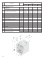
!^_
6
6A
6B
6C
6D
6E
6F
6G
Complete
Jacket Top Panel
Jacket Top Panel Main Insulation
Jacket Upper Rear Panel
Jacket Upper Rear Panel Insulation
Jacket Lower Rear Panel
Jacket Upper Front Panel
Jacket Front Removable Panel
6H
Jacket Left Side Panel
6J
Jacket Left Side Panel Main Insulation Piece
72016021
1
1
1
1
6K
Jacket Left Side Panel Upper Corner Insulation Piece
72016023
1
1
1
1
6L
Jacket Left Side Panel Lower Corner Insulation Piece
72016022
1
1
1
1
6M
Jacket Right Side Panel
60416021
1
1
1
1
6N
Jacket Right Side Panel Main Insulation Piece
72016011
1
1
1
1
6P
Jacket Right Side Panel Lower Corner Insulation Piece
72016012
1
1
1
1
704160794
1
---
---
---
704160894
---
1
---
---
704160994
---
---
1
---
704161094
---
---
---
1
72016077
1
---
---
---
72016087
---
1
---
---
72016097
---
---
1
---
72016107
---
---
---
1
6Q
6R
Jacket Vestibule Panel
Jacket Vestibule Panel Upper Insulation Piece
59
60
Quantity
Item
No.
Description
Part No.
16H-340
16H-410
16H-460
16H-505
72016076
1
---
---
---
72016086
---
1
---
---
72016096
---
---
1
---
72016106
---
---
---
1
704160792
1
---
---
---
704160892
---
1
---
---
704160992
---
---
1
---
704161092
---
---
---
1
7201619
1
---
---
---
7201620
---
1
---
---
7201621
---
---
1
---
7201622
---
---
---
1
7201612
1
---
---
---
7201614
---
1
---
---
7201616
---
---
1
---
7201618
---
---
---
1
!^_|4
6S
6T
6U
6V
Jacket Vestibule Panel Lower Insulation Piece
Jacket Lower Front Tie Bar
Jacket Lower Rear Panel Insulation
Jacket Top Panel Front Insulation
61
Quantity
Item
No.
Description
Part No.
16H-340
16H-410
16H-460
16H-505
35-3300
80160474
1
1
1
1
Immersion Well, ¾” NPT x 1½” Insul. Depth
35-1010
1
1
1
1
B
Limit, Manual Reset, Honeywell L4006E1133
3503101
Optional on EI,
Standard on
EP-CSD-1
Optional on EI,
Standard on
EP-CSD-1
Optional on EI,
Standard on
EP-CSD-1
Optional on EI,
Standard on
EP-CSD-1
B1
Immersion Well, ¾” NPT x 3” Insul. Depth
35-1020
1
1
1
1
C
Temperature - Pressure Gauge
95-069
1
1
1
1
C1
Nipple, 2 NPT x 10” w/Gauge Tapping
D
Safety Relief Valve, ¾ NPT, 50 psi
D1
Nipple, ¾ NPT x 3½”
7. Trim and Miscellaneous Controls
A
E
E1
E2
Limit, 140-220°F, Honeywell
L4080D1218 (EI)
L4080B1212 (EP)
950210
1
1
1
1
81660302
1
1
1
1
Procure
Locally
1
1
1
1
Drain Valve, ¾ NPT, Conbraco 35-302-03
95-041
1
1
1
1
Nipple, ¾ NPT x 3½”
Procure
Locally
1
1
1
1
95-056
1
1
1
1
F
Blocked Vent Switch Replacement Assembly
6016058
1
1
1
1
G
Flame Roll-out Switch
960122
1
1
1
1
G1
Flame Roll-out Switch Mounting Bracket
900122
1
1
1
1
H
Junction Box
96-055
1
1
1
1
J
Control Center, Honeywell R8285D5001
(Intermittent Circulation builds)
3505555
1
1
1
1
L
Ignition Module, Honeywell S8610M3009
3505020
1
1
1
1
Vestibule Wiring Harness, Complete with Vent Damper
Bypass Plug (EI) (Not Depicted)
81316010
1
---
---
---
81316011
---
1
1
1
M
62
Coupling, ¾ NPT
(OPTIONAL:
USA:
16H-340
THRU
16H-505)
OPTIONAL:
16H-340
THRU
16H-505
(CANADA: 16H-340 ONLY)
Quantity
Item
No.
Description
Part No.
16H-340
16H-410
16H-460
16H-505
260136
1
---
---
---
260138
---
1
---
---
260139
---
---
1
1
Automatic Vent Damper, 8”
96-035
1
---
---
---
Automatic Vent Damper, 9”
96-036
---
1
---
---
Automatic Vent Damper, 10”
96-037
---
---
1
1
@!
$
8A
Draft Hood
8B
63
&
Manufacturer of Hydronic Heating Products
P.O. Box 14818 3633 I. Street
Philadelphia, PA 19134
www.crownboiler.com
)zTCGNF
%
N@R
;#G*L'NF