1
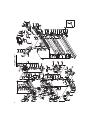
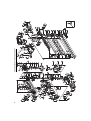
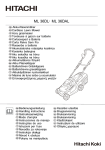
Hedge Trimmer
Heckenschere
Taille-Haies
Tosasiepi
Motor heggenschaar
Cortasetos
Corta-sebes
Häcksax
Hækkeklipper
Hekksaks
Pensasleikkuri
CH 22EAP2 (50ST)/CH 22EA2 (50ST)/CH 22EBP2 (62ST)
CH 22EB2 (62ST)/CH 22ECP2 (62ST)/CH 22EC2 (62ST)
CH 22ECP2 (78ST)/CH 22EC2 (78ST)
CH22ECP2 (62ST)
Read the manual carefully before operating this machine.
Lesen Sie vor der Verwendung diese Anleitung sorgfältig durch.
Lire attentivement le manuel avant d’utiliser la machine.
Leggere attentamente il manuale prima di mettere in funzione questa apparecchiatura.
Lees de handleiding zorgvuldig door voordat u de machine bedient.
Antes de utilizar esta máquina, lea cuidadosamente el manual.
Leia o manual atentamente antes de operar esta máquina.
Läs noga igenom bruksanvisningen innan maskinen tas i bruk.
Læs denne brugsvejledning omhyggeligt, inden maskinen tages i brug.
Bruksanvisningen må leses nøye før bruk av maskinen.
Lue ohjekirja huolellisesti ennen koneen käyttämistä.
Handling instructions
Bedienungsanleitung
Mode d’emploi
Istruzioni per l’uso
Gebruiksaanwijzing
Instrucciones de manejo
Instruções de uso
Bruksanvisning
Brugsanvisning
Bruksanvisning
Käyttöohjeet
1
2
3
2
1
3
A
4
5
6
4
C
B
5
7
8
6
E
D
2
F
9
10
11
T
0.6 mm
2
12
13
15
16
14
7
3
English
(Original instructions)
MEANINGS OF SYMBOLS
NOTE: Some units do not carry them.
Symbols
WARNING
The following show symbols used for the machine. Be sure that you understand their meaning before use.
It is important that you read, fully understand and
observe the following safety precautions and
warnings. Careless or improper use of the unit may
cause serious or fatal injury.
O /Stop
Read, understand and follow all warnings and
instructions in this manual and on the unit.
Emergency stop
Always wear eye, head and ear protectors when using
this unit.
Fuel and oil mixture
Choke - Run position (Open)
Hot surface
Choke - Choked position (Closed)
On/Start
Contents
WHAT IS WHAT? .............................................................................. 5
WARNINGS AND SAFETY INSTRUCTIONS .................................. 6
SPECIFICATIONS ............................................................................ 7
OPERATING PROCEDURES ........................................................... 7
MAINTENANCE ................................................................................ 8
TROUBLESHOOTING ...................................................................... 9
4
Before using your machine
• Read the manual carefully.
• Check that the cutting equipment is correctly
assembled and adjusted.
• Start the unit and check the carburetor adjustment.
See “MAINTENANCE”.
English
WHAT IS WHAT?
Since this manual covers several models, there may be some
di erence between these illustrations and your unit. Use the
instructions that apply to your unit.
1.
2.
3.
4.
5.
6.
7.
8.
9.
10.
11.
12.
13.
14.
15.
16.
17.
18.
19.
5
16
1
8
12
11
3
6
Recoil starter
Fuel tank
Throttle lever lockout
Throttle lever
Front handle
Rear handle
Spark plug
Hand guard
Cutting blade
Air cleaner
Stop switch
Blade guide
Gear case
Choke lever
Lock lever
Priming pump
Blade case
Combi box spanner
Handling instructions
9
4
15
2
10
14
7
13
CH 22EAP2 (50ST), CH 22EA2 (50ST)
CH 22EBP2 (62ST), CH 22EB2 (62ST)
CH 22ECP2 (62ST), CH 22EC2 (62ST)
CH 22ECP2 (78ST), CH 22EC2 (78ST)
18
19
17
5
English
WARNINGS AND SAFETY INSTRUCTIONS
Keep for future reference.
THIS HEDGE TRIMMER CAN CAUSE SERIOUS INJURIES. Read
the instructions carefully for the correct handling, preparation,
maintenance, starting and stopping of the hedge trimmer. Become
familiar with all controls and the proper use of the hedge trimmer.
Operator safety
Always wear a safety face shield or goggles.
Always wear heavy, long pants, boots and gloves. Do not wear
loose clothing, jewelry, short pants, sandals or go barefoot.
Secure hair so it is above shoulder length.
Do not operate this tool when you are tired, ill or under the
influence of alcohol, drugs or medication.
Never let a child or inexperienced person operate the machine.
Beware of overhead power lines.
Wear hearing protection.
Never start or run the engine inside a closed room or building.
Breathing exhaust fumes can kill.
Keep handles free of oil and fuel.
Keep hands away from cutting equipment.
Do not grab or hold the unit by the cutting equipment.
When the unit is turned o , make sure the cutting attachment
has stopped before the unit is set down.
When operation is prolonged, take a break from time to time
so that you may avoid possible Hand-Arm Vibration Syndrome
(HAVS) which is caused by vibration.
If the cutting mechanism strikes any foreign object or the
hedge trimmer starts making any unusual noise or vibration,
shut o the power source and allow the hedge trimmer to stop.
Disconnect the spark plug wire from the spark plug and take the
following steps:
Inspect for damage;
Check for, and tighten, any loose parts;
Have any damaged parts replaced or repaired with parts
having equivalent specifications.
WARNING
Antivibration systems do not guarantee that you will not sustain
Hand-Arm Vibration Syndrome or carpal tunnel syndrome.
Therefore, continual and regular users should monitor closely
the condition of their hands and fingers. If any symptoms of the
above appear, seek medical advice immediately.
If you are using any medical electric/electronic devices such
as a pacemaker, consult your physician as well as the device
manufacturer prior to operating any power equipment.
When a foreign object is caught in the blade, turn o the
engine, and remove the foreign object carefully using a plier
etc., after the hedge trimmer has been cooled down. Be careful
when removing the foreign object, since the blade may move
because of the backlash.
Unit/machine safety
Inspect the entire unit/machine before each use. Replace
damaged parts. Check for fuel leaks and make sure all
fasteners are in place and securely tightened.
Replace parts that are cracked, chipped or damaged in any way
before using the unit/machine.
Keep others away when making carburetor adjustments.
Use only accessories as recommended for this unit/machine by
the manufacturer.
WARNING
Never modify the unit/machine in any way. Do not use your unit/
machine for any job except that for which it is intended.
Fuel safety
Mix and pour fuel outdoors and where there are no sparks or
flames.
Use a container approved for fuel.
Never remove the fuel cap or add fuel with the power source
running. Allow engine and exhaust components to cool down
before refuelling.
Do not smoke or allow smoking near fuel or the unit/machine or
while using the unit/machine.
Never refuel indoors.
Wipe up all fuel spills before starting engine.
6
Move at least 3 m away from fueling site before starting engine.
Stop engine before removing fuel cap.
Empty the fuel tank before storing the unit/machine. It is
recommended that the fuel be emptied after each use. If fuel is
left in the tank, store so fuel will not leak.
Store unit/machine and fuel in area where fuel vapors cannot
reach sparks or open flames from water heaters, electric motors
or switches, furnaces, etc.
WARNING
Fuel is easy to ignite or get explosion or inhale fumes, so that
pay special attention when handling or filling fuel.
Cutting safety
Do not cut any material other than plant hedge.
Inspect the area to be cut before each use. Remove objects
which can be thrown or become entangled.
For respiratory protection, wear an aerosol protection mask
when cutting the grass after insecticide is scattered.
Keep others including children, animals, bystanders and
helpers outside the 15 m hazard zone. Stop the engine
immediately if you are approached.
Hold the unit/machine firmly with both hands.
Keep firm footing and balance. Do not over-reach.
Keep all parts of your body away from the mu er and cutting
attachment when the engine is running.
Keep cutting tool below shoulder level. NEVER operate unit
from a ladder, while in a tree or from any unstable support.
When relocating to a new work area, be sure to shut o the
machine and ensure that all cutting attachments are stopped.
Never place the machine on the ground when running.
Always carry a first-aid kit when operating any power
equipment.
Never start or run the engine inside a closed room or building
and/or near the inflammable liquid. Breathing exhaust fumes
can kill.
Maintenance safety
Maintain the unit/machine according to recommended
procedures.
Disconnect the spark plug before performing maintenance
except for carburetor adjustments.
Keep others away when making carburetor adjustments.
Use only genuine Hitachi replacement parts as recommended
by the manufacturer.
When the hedge trimmer is stopped for servicing, inspection or
storage, shut o the power source, disconnect the spark plug
wire from the spark plug and make sure all moving parts have
come to a stop.
Allow the hedge trimmer to cool before making any inspection,
adjustments, etc.
Transport and storage
Carry the unit/machine by hand with the engine stopped and
the mu er away from your body.
Allow the engine to cool, empty the fuel tank, and secure the
unit/machine before storing or transporting in a vehicle.
Empty the fuel tank before storing the unit/machine. It is
recommended that the fuel be emptied after each use. If fuel is
left in the tank, store so fuel will not leak.
Store unit/machine out of the reach of children.
Clean and maintenance the unit carefully and store it in a dry
place.
Make sure engine switch is o when transporting or storing.
When transporting in a vehicle or storage, cover blade with
blade cover.
If situations occur which are not covered in this manual, take care
and use common sense. Contact your Hitachi dealer if you need
assistance. Pay special attention to statements preceded by the
following words:
WARNING
Indicates a strong possibility of severe personal injury or loss of
life, if instructions are not followed.
CAUTION
Indicates a possibility of personal injury or equipment damage,
if instructions are not followed.
English
NOTE
Helpful information for correct function and use.
CAUTION
Do not disassemble the recoil starter. you may get a possibility
of personal injury with recoil spring.
SPECIFICATIONS
MODEL
Engine Size (ml)
Spark Plug
Fuel Tank Capacity (l)
Dry Weight (kg)
Overall blade length (mm)
CH22EAP2 (50ST)
CH22EA2 (50ST)
CH22EBP2 (62ST)
CH22EB2 (62ST)
CH22ECP2 (78ST)
CH22EC2 (78ST)
21.1
NGK BMR 7A (Europe and Australia) or Champion CJ 6 (other regions)
0.30
4.3
4.7
5.0
5.2
500
620
620
780
Double-sided
Blade type
Sound pressure level
LpA (dB(A)) (ISO 10517)
Sound power level
Lw measured (dB (A))
(2000/14/EC, ISO 10517)
LwA (dB (A))
Vibration level (m/s2) (ISO 10517)
Front handle
Rear handle
CH22ECP2 (62ST)
CH22EC2 (62ST)
97
102
104
7.0
7.5
9.1
9.1
2.8
3.4
2.8
2.8
NOTE
Equivalent noise level/vibration level are calculated as the time-weighted energy total for noise/vibration levels under various working
conditions with the following time distribution : ISO 10517.....1/5 idle, 4/5 racing. 2000/14/EC.....only racing.
* All data subject to change without notice.
OPERATING PROCEDURES
Fuel (Fig. 1)
WARNING
The hedge trimmer is equipped with a two- stroke engine.
Always run the engine on fuel, mixed with oil.
Provide good ventilation, when fueling or handling fuel.
Fuel
Always use branded 89 octane unleaded gasoline.
Use genuine two-cycle oil or use a mix between 25:1 to 50:1,
please consult the oil bottle for the ratio or Hitachi dealer.
If genuine oil is not available, use an anti-oxidant added quality
oil expressly labeled for air-cooled 2-cycle engine use (JASO
FC GRADE OIL or ISO EGC GRADE). Do not use BIA or TCW
(2-stroke water-cooling type) mixed oil.
Never use multi-grade oil (10W/30) or waste oil.
Always mix fuel and oil in a separate clean container.
Always start by filling half the amount of fuel, which is to be used.
Then add the whole amount of oil. Mix (shake) the fuel mixture. Add
the remaining amount of fuel.
Mix (shake) the fuel-mix thoroughly before filling the fuel tank.
Fueling
WARNING (Fig. 2)
Always shut o the engine before refueling.
Slowly open the fuel tank (1), when filling up with fuel, so that
possible over-pressure disappears.
Tighten the fuel cap carefully, after fueling.
Always move the unit at least 3 m from the fueling area before
starting.
Before fueling, clean the tank cap area carefully, to ensure that
no dirt falls into the tank. Make sure that the fuel is well mixed by
shaking the container, before fueling.
Starting
CAUTION
Before starting, make sure the cutting attachment does not
touch anything.
1. Set stop switch (2) to ON position (A). (Fig. 3)
* Push priming pump (4) several times so that fuel flows through
the pump or return pipe. (Fig. 4)
2.
3.
4.
Set choke lever (5) to CLOSED position (B). (Fig. 5)
Pull recoil starter briskly, taking care to keep the handle in your
grasp and not allowing it to snap back. (Fig. 6)
When you hear the engine attempts to start, return choke lever
to RUN position (open) (C). Then pull recoil starter briskly
again.
NOTE
If engine does not start, repeat procedures from 2 to 4.
5.
After starting engine, allow the engine about 2-3 minutes to
warm up before subjecting it to any load.
Cutting
When cutting, operate engine at full throttle as this maintains proper
blade speed. When trimming top of hedge, hold trimmer so blades
are between 15 and 30 degrees from a horizontal position and
swing trimmer in an arc toward edge of hedge to sweep cuttings o .
When trimming sides of hedge, hold blade vertically and swing unit
in an arc.
NOTE
Multi-position twist handle (Fig. 7)
The rear control handle turns 90 degrees to provide
comfortable use while accommodating a variety of cutting
angles. The handle allows for five di erent locking positions.
Before attempting to adjust rear handle, make sure the machine
is at idle or engine is shut o .
The throttle lever cannot be engaged if the handle is not
secured (the lock lever is pressed).
To rotate the handle; push the lock lever (6) allowing the handle
to turn. Rotate the handle to the desired 0°, 45° or 90° locking
position and release the lock lever (6) to lock the handle in
place.
D: LOCK
E: UNLOCK
Stopping (Fig. 8)
Decrease engine speed, and push stop switch to stop position (F).
NOTE
If the engine does not stop, it can be forced to stop by rotating
the choke lever to the choked position.
Before restarting the engine, ask Hitachi Authorized Service
Centers for repairs.
7
English
MAINTENANCE
MAINTENANCE, REPLACEMENT OR REPAIR OF THE EMISSION
CONTROL DEVICES AND SYSTEM MAY BE PERFORMED
BY ANY NONROAD ENGINE REPAIR ESTABLISHMENT OR
INDIVIDUAL.
Carburetor adjustment (Fig. 9)
WARNING
The cutting attachment may be spinning during carburetor
adjustments.
Never start the engine without the complete cleaner cover.
Otherwise the clutch can come loose and cause personal
injuries.
In the carburetor, fuel is mixed with air. When the engine is test run
at the factory, the carburetor is adjusted. A further adjustment may
be required, according to climate and altitude. The carburetor has
one adjustment possibility:
T = Idle speed adjustment screw.
Idle speed adjustment (T)
Check that the air filter is clean. When the idle speed is correct, the
cutting attachment will not rotate. If adjustment is required, close
(clockwise) the T-screw, with the engine running, until the cutting
attachment starts to rotate. Open (counter-clockwise) the screw
until the cutting attachment stops. You have reached the correct idle
speed when the engine runs smoothly in all positions well below the
rpm when the cutting attachment starts to rotate.
If the cutting attachment still rotates after idle speed adjustment,
contact Hitachi dealer.
Air filter (Fig. 10)
The air filter must be cleaned from dust and dirt in order to avoid:
Carburetor malfunctions.
Starting problems.
Engine power reduction.
Unnecessary wear on the engine parts.
Abnormal fuel consumption.
Clean the air filter daily or more often if working in exceptionally
dusty areas.
Cleaning the air filter
Remove the cleaner cover and the fi lter. Rinse it in warm soap suds.
Check that the filter is dry before reassembly. An air filter that has
been used for some time cannot be cleaned completely. Therefore,
it must regularly be replaced by a new one. A damaged filter must
always be replaced.
NOTE
Saturate the element in 2-cycle oil or the equivalent. Squeeze
the element to distribute the oil completely and to remove any
excess oil.
Spark plug (Fig. 11)
The spark plug condition is influenced by:
An incorrect carburetor setting.
Wrong fuel mixture (too much oil in the gasoline).
A dirty air filter.
Hard running conditions (such as cold weather).
These factors cause deposits on the spark plug electrodes, which
may result in malfunction and starting di culties. If the engine
is low on power, di cult to start or runs poorly at idling speed,
always check the spark plug fi rst. If the spark plug is dirty, clean it
and check the electrode gap. Readjust if necessary. The correct
gap is 0.6 mm. The spark plug should be replaced after about 100
operation hours or earlier if the electrodes are badly eroded.
NOTE
In some areas, local law requires using a resistor spark plug
to suppress ignition signals. If this machine was originally
equipped with resistor spark plug, use the same type of spark
plug for replacement.
8
Lubricating the blade (Fig.12)
During trimming, sap adhering to the blade edge will increase load.
Use machine oil (or bicycle oil or the like) to lubricate the blade and
wipe the blade with a cloth. To prevent the blade from rusting, be
sure to lubricate the blade after use and when it will not be used for
an extended period of time before placing it in the blade case.
Gear case (Fig. 13)
Apply a good quality lithium based grease through the grease fitting
until a small amount comes out between the cutting blades and the
gear case. Lubricate the grease from the grease nipple (indicated
by an arrow) next to the gear case using a commercially available
cartridge grease gun.
NOTE
Lubrication should be applied 3g at 20 hour intervals and more
frequently with heavy use.
Fuel filter (Fig. 14)
Remove the fuel filter from the fuel tank and thoroughly wash it in
solvent. After that, push the filter into the tank completely.
NOTE
If the filter is hard due to dust and dirt, replace it.
Cleaning the cylinder fins (Fig. 15)
When leaves get caught between cylinder fins (7), the engine may
overheat, resulting in lower output. To avoid this, always keep
cylinder fi ns and cylinder cover clean.
Every 100 operating hours, or once a year (more often if conditions
require), clean fins and external surfaces of engine of dust, dirt and
oil deposits which can contribute to improper cooling.
Cleaning the mu er (Fig. 16)
Remove the mu er and spark arrestor (if so equipped), and clean
out any excess carbon from the exhaust port or mu er inlet every
100 hours of operation.
For long-term storage
Drain all fuel from the fuel tank. Start and let engine run until it stops.
Repair any damage which has resulted from use. Clean the unit with
a clean rag, or high pressure air hose. Put a few drops of two-cycle
engine oil into the cylinder through the spark plug hole, and spin the
engine over several times to distribute oil. Cover the unit and store
it in a dry area.
Maintenance schedule
Below you will find some general maintenance instructions. For
further information please contact your Hitachi dealer.
Daily maintenance
Clean the exterior of the hedge trimmer.
Check the blade guide for damage or cracks. Change the guard
in case of impacts or cracks.
Check that the blade is sharp, and without cracks.
Check that the blade nut is su ciently tightened.
Make sure that the blade blunt guard is undamaged and that it
can be securely fitted.
Check that nuts and screws are su ciently tightened.
Weekly maintenance
Check the starter, especially cord and return spring.
Clean the exterior of the spark plug.
Remove it and check the electrode gap. Adjust it to 0.6 mm, or
change the spark plug.
Clean the cooling fins on the cylinder and check that the air
intake at the starter is not clogged.
Check gear case is filled with grease.
Clean the air filter.
Monthly maintenance
Rinse the fuel tank with gasoline.
Clean the exterior of the carburetor and the space around it.
Clean the fan and the space around it.
English
TROUBLESHOOTING
Use the inspections in the table below if the tool does not operate normally. If this does not remedy the problem, consult your dealer or the
Hitachi Authorized Service Center.
Symptom
Tool
Possible cause
Remedy
Does not operate.
Foreign matter is lodged in the blade.
When there is foreign matter in the blade, use a
pair of tongs or similar tool to remove it.
Take great care since the tool may start
operating when the foreign matter has been
removed.
Sap or rust may also prevent the blade from
operating. Use a wire brush or similar tool to
remove sap or rust.
The tool does not trim well.
The blade stopped because it was used to cut
a branch whose width exceeded the blade’s
cutting capacity.
NOTE
Work that will repeatedly cause the blade to
stop will eventually damage the tool.
Some garden trees have wood that is very
hard and may be beyond the capacity of the
tool even if it is of a width that is within normal
capacity. Use a pair of pruning shear to remove
thick branches before starting work.
An oblique cut may also exceed the capacity of
the tool since the length of the cut increases.
Be sure to trim thick branches at right angles.
9
74
CH22EA2 (50ST)
CH22EA2 (50ST)
Item
No.
1
2
3
4
5
6
7
8
9
10
11
12
13
14
15
16
17
18
19
20
21
22
23
24
25
26
27
28
29
30
31
32
33
34
35
36
37
38
39
40
41
42
43
44
45
46
47
48
49
50
51
52
53
54
55
56
57
58
Part Name
Q’TY
COVER FIXING BOLT COMP.
CLEANER COVER
CLEANER SPONGE
CHOKE VALVE
MACHINE SCREW
(W/WASHERS) M5×60
CLEANER BODY
CHOKE HANDLE
TAPPING SCREW (W/FLANGE)
D4×12
THROTTLE ADJUST SCREW
(TAS)
SET SCREW (B)
SET SCREW (D)
SYRINGE
PRIMER BASE
PUMP GASKET
PUMP DIAPHRAGM
STRAINER
GUIDE PIN ROLLER
SYRINGE RETAINER
SET SCREW (E)
BALL PLUG RETAINER
ADJUSTING SCREW
(MAIN MIXTURE)
METERING LEVER SPRING
PIN
METERING DIAPHRAGM
METERING COVER
SET SCREW (C)
POST
ROTOR COVER
RETAINING RING (E-TYPE) FOR
D2.5 SHAFT
O-RING
INLET NEEDLE VALVE
SET SCREW (A)
METERING LEVER
METERING GASKET
CARBURETOR ASS'Y
(INCLUD.9-34)
LOCK NUT M6
CARBURETOR INSULATOR
INTAKE PACKING
GLASS WASHER
CARBURETOR PACKING
SEAL LOCK HEX. SOCKET
BOLT (W/WASHERS)M5×25
HEX. SOCKET HD. BOLT
(W/WASHERS) M4×18
CORD
SEAL LOCK HEX. SOCKET HD.
BOLT M4×12
CYLINDER COVER
METAL OF PLUG CAP (60) (B)
PLUG CAP
CORD INSULATION TUBE
IGNITION COIL
SPARK PLUG
CYLINDER
COVER PACKING
INTAKE COVER (A)
SEAL LOCK SCREW M4×10
HEAT PROTECTION PANEL
MUFFLER
BOLT WASHER M6
HEX. SOCKET HD. BOLT M6×55
1
1
1
1
2
1
1
1
1
3
4
1
1
1
1
1
1
1
1
1
1
1
1
1
1
3
1
1
1
1
1
1
1
1
1
1
1
1
4
1
2
Item
No.
59
60
61
62
63
64
65
66
67
68
69
70
71
72
73
74
75
76
77
78
79
80
81
82
83
84
85
86
87
88
89
90
91
92
93
94
95
96
97
98
99
2
100
1
101
102
103
104
105
1
1
1
1
1
1
1
1
2
1
4
1
1
2
2
106
107
108
109
110
111
112
113
114
115
Part Name
Q’TY
INTAKE COVER (B)
PISTON PIN
PISTON
HEX. SOCKET HD. BOLT
(W/SP.WASHER) M5×18
CYLINDER PACKING
PISTON RING
CIR CLIP
FLYWHEEL NUT M7
BOLT WASHER D7
STARTER PAWL
STARTER PAWL SPRING
MAGNETO ROTOR
RETAINING RING D4
CRANK CASE (B) ASS'Y
(INCLUD.73,74)
OIL SEAL TB 12227
BALL BEARING 6001C3
SHIM T0.2
SHIM T0.3
CRANK SHAFT
CRANK CASE (A) ASS'Y
(INCLUD.73,74,80)
CRANK CASE PACKING
KNOCK PIN 4×12
CLUTCH ASS'Y (B)
CLUTCH DRUM
BALL BEARING 6002ZC3
RETAINING RING FOR D15
SHAFT
GREASE NIPPLE COMP.
TAPPING SCREW (W/FLANGE)
D5X20
MUFFLER PROTECTOR
MACHINE SCREW
(W/SP.WASHERS) M5×16
HEX. HOLE BOLT 6×18/S
HEX. SOCKET HD. BOLT
(W/BUTTON) M5×20
FIXATION PLATE (A)
FIXATION PLATE (B)
TAIL PIPE (A)
EXHAUST COVER
HITACHI LABEL
TAPPING SCREW D4.5×16
PLATE
STARTER KNOB
STARTER ROPE
HEX. SOCKET HD. BOLT
(W/BUTTON) M5×20
RECOIL SPRING
STARTER ROPE REEL
DAMPER SPRING
CAM PLATE
SET SCREW
RECOIL STARTER ASS'Y
(INCLUD.97-99,101-105)
AIR DEFLECTOR
FUEL TANK CAP ASS'Y
(INCLUD.109)
TANK CAP CHAIN
FUEL GROMMET
FUEL PIPE
FUEL PIPE (PINK)
RETURN GROMMET
CLIP
PUMP FILTER
1
1
1
8
1
1
2
1
1
2
2
1
2
1
2
2
1
1
1
1
1
2
1
1
2
1
Item
No.
116
117
141
142
143
144
145
146
147
148
149
150
151
152
153
154
155
156
157
158
159
160
161
162
163
164
1
165
166
167
1
168
1
169
170
171
172
173
1
4
2
1
1
1
1
1
1
1
1
1
3
1
1
1
1
1
174
175
176
177
178
179
180
181
182
501
Part Name
Q’TY
CUSHION RUBBER
TANK
NAME PLATE
HANDLE
SEAL LOCK HEX. SOCKET HD.
BOLT M5×40
SPRING WASHER M5
BRAKE AXIS WASHER
HANDLE A
CAUTION LABEL
SPRING (A)
LOCK LEVER
THROTTLE LEVER
TRIGGER LOCKOUT
THROTTLE LEVER SPRING
STOP SWITCH
HANDLE B
TAPPING SCREW (W/FLANGE)
D4×16
THROTTLE WIRE
PROTECTION TUBE
STOP SWITCH CORD
STOP SWITCH CORD (B)
FIXATION PLATE (B)
NYLON NUT M5
SMALL WASHER 5
SPACER
HEX. SOCKET HD. BOLT
(W/BUTTON) M5×25
U-NUT M5
WASHER (B)
WASHER M7
SHOULDER BUTTON BOLT
M5×25
BLADE ASS'Y (INCLUD.164-168)
BLADE CASE (A)
HANDLE BRACKET
CLIP
BOLT WASHER D5
SEAL LOCK HEX. SOCKET
BOLT (W/WASHERS) M5×16
GEAR CASE (A) ASS'Y
(INCLUD.176)
GUIDE PLATE (C)
GEAR 2
GUIDE PLATE (A)
FELT PACKING (A)
GEAR CASE PACKING
GEAR CASE COVER
HEX. SOCKET HD. BOLT
(W/SP.WASHER) M5×12
BOX WRENCH 10/19MM
4
1
1
1
2
2
2
1
1
1
1
1
1
1
1
1
4
1
1
1
1
1
2
2
1
2
5
5
5
5
1
1
1
1
3
3
1
1
1
1
1
1
1
6
1
1
1
1
1
1
1
1
1
1
1
75
76
CH22EBP2 (62ST)
CH22EBP2 (62ST)
Item
No.
1
2
3
4
5
6
7
8
9
10
11
12
13
14
15
16
17
18
19
20
21
22
23
24
25
26
27
28
29
30
31
32
33
34
35
36
37
38
39
40
41
42
43
44
45
46
47
48
49
50
51
52
53
54
55
56
57
58
59
Part Name
Q’TY
COVER FIXING BOLT COMP.
CLEANER COVER
CLEANER SPONGE
CHOKE VALVE
MACHINE SCREW
(W/WASHERS) M5×60
CLEANER BODY
CHOKE HANDLE
TAPPING SCREW (W/FLANGE)
D4×12
THROTTLE ADJUST SCREW
(TAS)
SET SCREW (B)
SET SCREW (D)
SYRINGE
PRIMER BASE
PUMP GASKET
PUMP DIAPHRAGM
STRAINER
GUIDE PIN ROLLER
SYRINGE RETAINER
SET SCREW (E)
BALL PLUG RETAINER
ADJUSTING SCREW
(MAIN MIXTURE)
METERING LEVER SPRING
PIN
METERING DIAPHRAGM
METERING COVER
SET SCREW (C)
POST
ROTOR COVER
RETAINING RING (E-TYPE) FOR
D2.5 SHAFT
O-RING
INLET NEEDLE VALVE
SET SCREW (A)
METERING LEVER
METERING GASKET
CARBURETOR ASS'Y
(INCLUD.9-34)
LOCK NUT M6
CARBURETOR INSULATOR
INTAKE PACKING
GLASS WASHER
CARBURETOR PACKING
SEAL LOCK HEX. SOCKET
BOLT (W/WASHERS)M5×25
HEX. SOCKET HD. BOLT
(W/WASHERS) M4×18
CORD
SEAL LOCK HEX. SOCKET HD.
BOLT M4×12
CYLINDER COVER
METAL OF PLUG CAP (60) (B)
PLUG CAP
CORD INSULATION TUBE
IGNITION COIL
SPARK PLUG
CYLINDER
COVER PACKING
INTAKE COVER (A)
SEAL LOCK SCREW M4×10
HEAT PROTECTION PANEL
MUFFLER
BOLT WASHER M6
HEX. SOCKET HD. BOLT M6×55
INTAKE COVER (B)
1
1
1
1
2
1
1
1
1
3
4
1
1
1
1
1
1
1
1
1
1
1
1
1
1
3
1
1
1
1
1
1
1
1
1
1
1
1
4
1
2
2
1
1
1
1
1
1
1
1
1
2
1
4
1
1
2
2
1
Item
No.
60
61
62
63
64
65
66
67
68
69
70
71
72
73
74
75
76
77
78
79
80
81
82
83
84
85
86
87
88
89
90
91
92
93
94
95
96
97
98
99
100
101
102
103
104
105
106
107
108
109
110
111
112
113
114
115
116
117
Part Name
Q’TY
PISTON PIN
PISTON
HEX. SOCKET HD. BOLT
(W/SP.WASHER) M5×18
CYLINDER PACKING
PISTON RING
CIR CLIP
FLYWHEEL NUT M7
BOLT WASHER D7
STARTER PAWL
STARTER PAWL SPRING
MAGNETO ROTOR
RETAINING RING D4
CRANK CASE (B) ASS'Y
(INCLUD.73,74)
OIL SEAL TB 12227
BALL BEARING 6001C3
SHIM T0.2
SHIM T0.3
CRANK SHAFT
CRANK CASE (A) ASS'Y
(INCLUD.73,74,80)
CRANK CASE PACKING
KNOCK PIN 4×12
CLUTCH ASS'Y (B)
CLUTCH DRUM
BALL BEARING 6002ZC3
RETAINING RING FOR D15
SHAFT
GREASE NIPPLE COMP.
TAPPING SCREW (W/FLANGE)
D5×20
MUFFLER PROTECTOR
MACHINE SCREW
(W/SP.WASHERS) M5×16
HEX. HOLE BOLT 6×18/S
HEX. SOCKET HD. BOLT
(W/BUTTON) M5×20
FIXATION PLATE (A)
FIXATION PLATE (B)
TAIL PIPE (A)
EXHAUST COVER
HITACHI LABEL
TAPPING SCREW D4.5×16
PLATE
STARTER KNOB
STARTER ROPE
HEX. SOCKET HD. BOLT
(W/BUTTON) M5×20
RECOIL SPRING
STARTER ROPE REEL
DAMPER SPRING
CAM PLATE
SET SCREW
RECOIL STARTER ASS'Y
(INCLUD.97-99,101-105)
AIR DEFLECTOR
FUEL TANK CAP ASS'Y
(INCLUD.109)
TANK CAP CHAIN
FUEL GROMMET
FUEL PIPE
FUEL PIPE (PINK)
RETURN GROMMET
CLIP
PUMP FILTER
CUSHION RUBBER
TANK
1
1
8
1
1
2
1
1
2
2
1
2
1
2
2
1
1
1
Item
No.
118
141
142
143
144
145
146
147
148
149
150
151
152
153
154
155
1
156
157
158
159
160
161
162
163
164
165
166
167
168
1
169
1
1
2
1
1
2
1
1
1
4
2
1
1
1
1
1
1
1
1
1
3
1
1
1
1
1
1
1
1
1
1
1
1
1
1
1
4
1
170
171
172
173
174
175
176
177
178
179
180
181
182
183
184
185
186
187
188
189
190
191
192
501
Part Name
Q’TY
CAUTION LABEL
NAME PLATE
HANDLE
SEAL LOCK HEX. SOCKET HD.
BOLT M5×40
SPRING WASHER M5
BRAKE AXIS WASHER
HANDLE A
CAUTION LABEL
SPRING (A)
LOCK LEVER
THROTTLE LEVER
TRIGGER LOCKOUT
THROTTLE LEVER SPRING
STOP SWITCH
HANDLE B
TAPPING SCREW (W/FLANGE)
D4×16
THROTTLE WIRE
PROTECTION TUBE
STOP SWITCH CORD
STOP SWITCH CORD (B)
FIXATION PLATE (B)
NYLON NUT M6
BOLT WASHER 6
U-NUT M5
WASHER (A)
RUBBER WASHER
COLLER
SUPPORT PLATE
BOLT WASHER D6
BLADE ASS'Y
(INCLUD.163,172-173)
HEX. SOCKET HD. BOLT
(W/FLANGE) M5×8
GUARD PLATE
HEX. SOCKET HD. BOLT
(W/BUTTON) M6×25
WASHER (A)
WASHER M7
SHOULDER BUTTON BOLT
M5×25
SHOULDER BUTTON BOLT
M5×31
BLADE CASE
HANDLE BRACKET
CLIP
BOLT WASHER D5
SEAL LOCK HEX. SOCKET
BOLT (W/WASHERS) M5×16
GEAR CASE (A) ASS'Y
(INCLUD.183)
BALL BEARING 608ZZC3
HEX. SOCKET HD. BOLT
(W/BUTTON) M6×25
GUIDE PLATE (B)
CAM ROD
GEAR 2
FELT PACKING (B)
FELT PACKING (C)
GEAR CASE PACKING
GEAR CASE (B) ASS'Y
(INCLUD.183)
HEX. SOCKET HD. BOLT
(W/SP.WASHER) M5×14
BOX WRENCH 10/19MM
1
1
1
2
2
2
1
1
1
1
1
1
1
1
1
4
1
1
1
1
1
2
2
5
2
2
1
1
2
1
1
1
1
5
5
4
1
1
1
1
3
3
1
2
1
2
2
1
2
1
1
1
6
1
77
78
CH22EB2 (62ST)
CH22EB2 (62ST)
Item
No.
1
2
3
4
5
6
7
8
9
10
11
12
13
14
15
16
17
18
19
20
21
22
23
24
25
26
27
28
29
30
31
32
33
34
35
36
37
38
39
40
41
42
43
44
45
46
47
48
49
50
51
52
53
54
55
56
57
58
59
Part Name
Q’TY
COVER FIXING BOLT COMP.
CLEANER COVER
CLEANER SPONGE
CHOKE VALVE
MACHINE SCREW
(W/WASHERS) M5×60
CLEANER BODY
CHOKE HANDLE
TAPPING SCREW (W/FLANGE)
D4×12
THROTTLE ADJUST SCREW
(TAS)
SET SCREW (B)
SET SCREW (D)
SYRINGE
PRIMER BASE
PUMP GASKET
PUMP DIAPHRAGM
STRAINER
GUIDE PIN ROLLER
SYRINGE RETAINER
SET SCREW (E)
BALL PLUG RETAINER
ADJUSTING SCREW
(MAIN MIXTURE)
METERING LEVER SPRING
PIN
METERING DIAPHRAGM
METERING COVER
SET SCREW (C)
POST
ROTOR COVER
RETAINING RING (E-TYPE) FOR
D2.5 SHAFT
O-RING
INLET NEEDLE VALVE
SET SCREW (A)
METERING LEVER
METERING GASKET
CARBURETOR ASS'Y
(INCLUD.9-34)
LOCK NUT M6
CARBURETOR INSULATOR
INTAKE PACKING
GLASS WASHER
CARBURETOR PACKING
SEAL LOCK HEX. SOCKET
BOLT (W/WASHERS)M5×25
HEX. SOCKET HD. BOLT
(W/WASHERS) M4×18
CORD
SEAL LOCK HEX. SOCKET HD.
BOLT M4×12
CYLINDER COVER
METAL OF PLUG CAP (60) (B)
PLUG CAP
CORD INSULATION TUBE
IGNITION COIL
SPARK PLUG
CYLINDER
COVER PACKING
INTAKE COVER (A)
SEAL LOCK SCREW M4×10
HEAT PROTECTION PANEL
MUFFLER
BOLT WASHER M6
HEX. SOCKET HD. BOLT M6×55
INTAKE COVER (B)
1
1
1
1
2
1
1
1
1
3
4
1
1
1
1
1
1
1
1
1
1
1
1
1
1
3
1
1
1
1
1
1
1
1
1
1
1
1
4
1
2
2
1
1
1
1
1
1
1
1
1
2
1
4
1
1
2
2
1
Item
No.
60
61
62
63
64
65
66
67
68
69
70
71
72
73
74
75
76
77
78
79
80
81
82
83
84
85
86
87
88
89
90
91
92
93
94
95
96
97
98
99
100
101
102
103
104
105
106
107
108
109
110
111
112
113
114
115
116
117
Part Name
Q’TY
PISTON PIN
PISTON
HEX. SOCKET HD. BOLT
(W/SP.WASHER) M5×18
CYLINDER PACKING
PISTON RING
CIR CLIP
FLYWHEEL NUT M7
BOLT WASHER D7
STARTER PAWL
STARTER PAWL SPRING
MAGNETO ROTOR
RETAINING RING D4
CRANK CASE (B) ASS'Y
(INCLUD.73,74)
OIL SEAL TB 12227
BALL BEARING 6001C3
SHIM T0.2
SHIM T0.3
CRANK SHAFT
CRANK CASE (A) ASS'Y
(INCLUD.73,74,80)
CRANK CASE PACKING
KNOCK PIN 4×12
CLUTCH ASS'Y (B)
CLUTCH DRUM
BALL BEARING 6002ZC3
RETAINING RING FOR D15
SHAFT
GREASE NIPPLE COMP.
TAPPING SCREW (W/FLANGE)
D5×20
MUFFLER PROTECTOR
MACHINE SCREW
(W/SP.WASHERS) M5×16
HEX. HOLE BOLT 6×18/S
HEX. SOCKET HD. BOLT
(W/BUTTON) M5×20
FIXATION PLATE (A)
FIXATION PLATE (B)
TAIL PIPE (A)
EXHAUST COVER
HITACHI LABEL
TAPPING SCREW D4.5×16
PLATE
STARTER KNOB
STARTER ROPE
HEX. SOCKET HD. BOLT (W/
BUTTON) M5×20
RECOIL SPRING
STARTER ROPE REEL
DAMPER SPRING
CAM PLATE
SET SCREW
RECOIL STARTER ASS'Y
(INCLUD.97-99,101-105)
AIR DEFLECTOR
FUEL TANK CAP ASS'Y
(INCLUD.109)
TANK CAP CHAIN
FUEL GROMMET
FUEL PIPE
FUEL PIPE (PINK)
RETURN GROMMET
CLIP
PUMP FILTER
CUSHION RUBBER
TANK
1
1
Item
No.
141
142
8
143
1
1
2
1
1
2
2
1
2
144
145
146
147
148
149
150
151
152
153
154
1
2
2
1
1
1
1
1
2
1
1
2
1
1
1
1
1
4
2
155
156
157
158
159
160
161
162
163
164
165
166
167
168
169
170
171
172
173
174
1
1
1
1
1
1
1
1
1
177
178
179
180
3
181
1
1
1
1
1
182
1
1
1
1
1
1
1
1
1
1
4
1
175
176
183
184
185
186
187
188
189
190
191
192
501
Part Name
Q’TY
NAME PLATE
HANDLE
SEAL LOCK HEX. SOCKET HD.
BOLT M5×40
SPRING WASHER M5
BRAKE AXIS WASHER
HANDLE A
CAUTION LABEL
SPRING (A)
LOCK LEVER
THROTTLE LEVER
TRIGGER LOCKOUT
THROTTLE LEVER SPRING
STOP SWITCH
HANDLE B
TAPPING SCREW (W/FLANGE)
D4×16
THROTTLE WIRE
PROTECTION TUBE
STOP SWITCH CORD
STOP SWITCH CORD (B)
FIXATION PLATE (B)
NYLON NUT M6
BOLT WASHER 6
U-NUT M5
WASHER (A)
RUBBER WASHER
COLLER
SUPPORT PLATE
BOLT WASHER D6
BLADE ASS'Y
(INCLUD.163,172-173)
HEX. SOCKET HD. BOLT
(W/FLANGE) M5×8
GUARD PLATE
HEX. SOCKET HD. BOLT
(W/BUTTON) M6×25
WASHER (A)
WASHER M7
SHOULDER BUTTON BOLT
M5×25
SHOULDER BUTTON BOLT
M5×31
BLADE CASE
HANDLE BRACKET
CLIP
BOLT WASHER D5
SEAL LOCK HEX. SOCKET
BOLT (W/WASHERS) M5×16
GEAR CASE (A) ASS'Y
(INCLUD.183)
BALL BEARING 608ZZC3
HEX. SOCKET HD. BOLT
(W/BUTTON) M6×25
GUIDE PLATE (B)
CAM ROD
GEAR 2
FELT PACKING (B)
FELT PACKING (C)
GEAR CASE PACKING
GEAR CASE (B) ASS'Y
(INCLUD.183)
HEX. SOCKET HD. BOLT
(W/SP.WASHER) M5×14
BOX WRENCH 10/19MM
1
1
2
2
2
1
1
1
1
1
1
1
1
1
4
1
1
1
1
1
2
2
5
2
2
1
1
2
1
1
1
1
5
5
4
1
1
1
1
3
3
1
2
1
2
2
1
2
1
1
1
6
1
79
80
CH22ECP2 (62ST) / CH22ECP2 (78ST)
CH22ECP2 (62ST) / CH22ECP2 (78ST)
Item
No.
1
2
3
4
5
6
7
8
9
10
11
12
13
14
15
16
17
18
19
20
21
22
23
24
25
26
27
28
29
30
31
32
33
34
35
36
37
38
39
40
41
42
43
44
45
46
47
48
49
50
51
52
53
54
55
56
57
58
Part Name
Q’TY
COVER FIXING BOLT COMP.
CLEANER COVER
CLEANER SPONGE
CHOKE VALVE
MACHINE SCREW
(W/WASHERS) M5×60
CLEANER BODY
CHOKE HANDLE
TAPPING SCREW (W/FLANGE)
D4×12
THROTTLE ADJUST SCREW
(TAS)
SET SCREW (B)
SET SCREW (D)
SYRINGE
PRIMER BASE
PUMP GASKET
PUMP DIAPHRAGM
STRAINER
GUIDE PIN ROLLER
SYRINGE RETAINER
SET SCREW (E)
BALL PLUG RETAINER
ADJUSTING SCREW
(MAIN MIXTURE)
METERING LEVER SPRING
PIN
METERING DIAPHRAGM
METERING COVER
SET SCREW (C)
POST
ROTOR COVER
RETAINING RING (E-TYPE)
FOR D2.5 SHAFT
O-RING
INLET NEEDLE VALVE
SET SCREW (A)
METERING LEVER
METERING GASKET
CARBURETOR ASS'Y
(INCLUD.9-34)
LOCK NUT M6
CARBURETOR INSULATOR
INTAKE PACKING
GLASS WASHER
CARBURETOR PACKING
SEAL LOCK HEX. SOCKET
BOLT (W/WASHERS)M5×25
HEX. SOCKET HD. BOLT
(W/WASHERS) M4×18
CORD
SEAL LOCK HEX. SOCKET HD.
BOLT M4×12
CYLINDER COVER
METAL OF PLUG CAP (60) (B)
PLUG CAP
CORD INSULATION TUBE
IGNITION COIL
SPARK PLUG
CYLINDER
COVER PACKING
INTAKE COVER (A)
SEAL LOCK SCREW M4×10
HEAT PROTECTION PANEL
MUFFLER
BOLT WASHER M6
HEX. SOCKET HD. BOLT
M6×55
1
1
1
1
2
1
1
1
1
3
4
1
1
1
1
1
1
1
1
1
1
1
1
1
1
3
1
1
Item
No.
59
60
61
62
63
64
65
66
67
68
69
70
71
72
73
74
75
76
77
78
79
80
81
82
83
84
85
86
1
87
1
1
1
1
1
88
1
92
93
94
95
96
97
98
1
1
1
4
1
2
2
1
1
1
1
1
1
1
1
1
2
1
4
1
1
2
2
89
90
91
99
100
101
102
103
104
105
106
107
108
109
110
111
112
113
114
115
116
Part Name
Q’TY
INTAKE COVER (B)
PISTON PIN
PISTON
HEX. SOCKET HD. BOLT
(W/SP.WASHER) M5×18
CYLINDER PACKING
PISTON RING
CIR CLIP
FLYWHEEL NUT M7
BOLT WASHER D7
STARTER PAWL
STARTER PAWL SPRING
MAGNETO ROTOR
RETAINING RING D4
CRANK CASE (B) ASS'Y
(INCLUD.73,74)
OIL SEAL TB 12227
BALL BEARING 6001C3
SHIM T0.2
SHIM T0.3
CRANK SHAFT
CRANK CASE (A) ASS'Y
(INCLUD.73,74,80)
CRANK CASE PACKING
KNOCK PIN 4X12
CLUTCH ASS'Y (B)
CLUTCH DRUM
BALL BEARING 6002ZC3
RETAINING RING FOR D15
SHAFT
GREASE NIPPLE COMP.
TAPPING SCREW (W/FLANGE)
D5×20
MUFFLER PROTECTOR
MACHINE SCREW
(W/SP.WASHERS) M5×16
TAIL PIPE
FIXATION PLATE (A)
MACHINE SCREW
(W/WASHERS) M4×10
FIXATION PLATE (B)
HEX. HOLE BOLT 6×18/S
HITACHI LABEL
TAPPING SCREW D4.5×16
PLATE
STARTER KNOB
STARTER ROPE
HEX. SOCKET HD. BOLT
(W/BUTTON) M5×20
RECOIL SPRING
STARTER ROPE REEL
DAMPER SPRING
CAM PLATE
SET SCREW
RECOIL STARTER ASS'Y
(INCLUD.97-99,101-105)
AIR DEFLECTOR
FUEL TANK CAP ASS'Y
(INCLUD.109)
TANK CAP CHAIN
FUEL GROMMET
FUEL PIPE
FUEL PIPE (PINK)
RETURN GROMMET
CLIP
PUMP FILTER
CUSHION RUBBER
TANK
1
1
1
8
1
1
2
1
1
2
2
1
2
1
2
2
1
1
1
1
1
2
1
1
2
1
1
1
1
1
Item
No.
117
141
142
143
144
145
146
147
148
149
150
151
152
153
154
155
156
157
158
159
160
161
162
163
164
165
166
167
168
169
171
1
1
172
1
174
1
4
1
1
1
1
1
173
175
176
177
178
179
3
180
1
1
1
1
1
181
182
183
184
1
185
1
186
187
188
189
190
191
1
1
1
1
1
1
1
1
4
1
192
193
501
Part Name
CAUTION LABEL
HEX. SOCKET HD. BOLT
(W/FLANGE) M6×32
FRONT HANDLE
CAUTION LABEL
FRAME
NAME PLATE
DAMPER
HANDLE A
FLEXIBLE GROMMET
SPRING (A)
LOCK LEVER
THROTTLE LEVER
TRIGGER LOCKOUT
THROTTLE LEVER SPRING
STOP SWITCH
HANDLE B
TAPPING SCREW (W/FLANGE)
D4×16 (BLACK)
THROTTLE WIRE
PROTECTION TUBE
STOP SWITCH CORD
STOP SWITCH CORD (B)
HEX. SOCKET HD. BOLT
(W/FLANGE) M6×22
CLIP
NYLON NUT M6
BOLT WASHER 6
U-NUT M5
WASHER (A) (FOR 620MM)
RUBBER WASHER
(FOR 620MM)
COLLAR (FOR 620MM)
SUPPORT PLATE
SPRING HOLDER
HEX. SOCKET HD. BOLT
(W/FLANGE) M5×10
ANTIVIBRATION SPRING
BLADE ASS'Y
(INCLUD.165,177-181)
HEX. SOCKET HD. BOLT
(W/FLANGE) M5×8
GUARD PLATE
HEX. SOCKET HD. BOLT
(W/BUTTON) M6×25
WASHER (A)
WASHER M7
SHOULDER BUTTON BOLT
M5×25
SHOULDER BUTTON BOLT
M5×31
BLADE CASE
GEAR CASE (A) ASS'Y
(INCLUD.184)
BALL BEARING 608ZZC3
HEX. SOCKET HD. BOLT
(W/BUTTON) M6×25
GUIDE PLATE (B)
CAM ROD
GEAR 2
FELT PACKING (B)
FELT PACKING (C)
GEAR CASE PACKING
GEAR CASE (B) ASS'Y
(INCLUD.184)
HEX. SOCKET HD. BOLT
(W/SP.WASHER) M5×14
BOX WRENCH 10/19MM
Q’TY
1
4
1
1
1
1
1
1
1
1
1
1
1
1
1
1
4
1
1
1
1
4
1
2
2
5
2
2
1
1
4
4
4
1
1
1
1
5
5
4
1
1
1
2
1
2
2
1
2
1
1
1
6
1
81
82
CH22EC2 (62ST) / CH22EC2 (78ST)
CH22EC2 (62ST) / CH22EC2 (78ST)
Item
No.
1
2
3
4
5
6
7
8
9
10
11
12
13
14
15
16
17
18
19
20
21
22
23
24
25
26
27
28
29
30
31
32
33
34
35
36
37
38
39
40
41
42
43
44
45
46
47
48
49
50
51
52
53
54
55
56
57
58
59
Part Name
Q’TY
COVER FIXING BOLT COMP.
CLEANER COVER
CLEANER SPONGE
CHOKE VALVE
MACHINE SCREW
(W/WASHERS) M5×60
CLEANER BODY
CHOKE HANDLE
TAPPING SCREW (W/FLANGE)
D4X12
THROTTLE ADJUST SCREW
(TAS)
SET SCREW (B)
SET SCREW (D)
SYRINGE
PRIMER BASE
PUMP GASKET
PUMP DIAPHRAGM
STRAINER
GUIDE PIN ROLLER
SYRINGE RETAINER
SET SCREW (E)
BALL PLUG RETAINER
ADJUSTING SCREW
(MAIN MIXTURE)
METERING LEVER SPRING
PIN
METERING DIAPHRAGM
METERING COVER
SET SCREW (C)
POST
ROTOR COVER
RETAINING RING (E-TYPE) FOR
D2.5 SHAFT
O-RING
INLET NEEDLE VALVE
SET SCREW (A)
METERING LEVER
METERING GASKET
CARBURETOR ASS'Y
(INCLUD.9-34)
LOCK NUT M6
CARBURETOR INSULATOR
INTAKE PACKING
GLASS WASHER
CARBURETOR PACKING
SEAL LOCK HEX. SOCKET
BOLT (W/WASHERS)M5×25
HEX. SOCKET HD. BOLT
(W/WASHERS) M4×18
CORD
SEAL LOCK HEX. SOCKET HD.
BOLT M4×12
CYLINDER COVER
METAL OF PLUG CAP (60) (B)
PLUG CAP
CORD INSULATION TUBE
IGNITION COIL
SPARK PLUG
CYLINDER
COVER PACKING
INTAKE COVER (A)
SEAL LOCK SCREW M4×10
HEAT PROTECTION PANEL
MUFFLER
BOLT WASHER M6
HEX. SOCKET HD. BOLT M6×55
INTAKE COVER (B)
1
1
1
1
2
1
1
1
1
3
4
1
1
1
1
1
1
1
1
1
1
1
1
1
1
3
1
1
1
1
1
1
1
1
Item
No.
60
61
62
63
64
65
66
67
68
69
70
71
72
73
74
75
76
77
78
79
80
81
82
83
84
85
86
87
88
89
90
91
1
1
1
4
1
92
93
94
95
96
97
98
2
99
1
2
1
1
1
1
1
1
1
1
1
2
1
4
1
1
2
2
1
100
101
102
103
104
105
106
107
108
109
110
111
112
113
114
115
116
Part Name
Q’TY
PISTON PIN
PISTON
HEX. SOCKET HD. BOLT
(W/SP.WASHER) M5×18
CYLINDER PACKING
PISTON RING
CIR CLIP
FLYWHEEL NUT M7
BOLT WASHER D7
STARTER PAWL
STARTER PAWL SPRING
MAGNETO ROTOR
RETAINING RING D4
CRANK CASE (B) ASS'Y
(INCLUD.73,74)
OIL SEAL TB 12227
BALL BEARING 6001C3
SHIM T0.2
SHIM T0.3
CRANK SHAFT
CRANK CASE (A) ASS'Y
(INCLUD.73,74,80)
CRANK CASE PACKING
KNOCK PIN 4×12
CLUTCH ASS'Y (B)
CLUTCH DRUM
BALL BEARING 6002ZC3
RETAINING RING FOR D15
SHAFT
GREASE NIPPLE COMP.
TAPPING SCREW (W/FLANGE)
D5X20
MUFFLER PROTECTOR
MACHINE SCREW
(W/SP.WASHERS) M5×16
TAIL PIPE
FIXATION PLATE (A)
MACHINE SCREW
(W/WASHERS) M4×10
FIXATION PLATE (B)
HEX. HOLE BOLT 6×18/S
HITACHI LABEL
TAPPING SCREW D4.5×16
PLATE
STARTER KNOB
STARTER ROPE
HEX. SOCKET HD. BOLT
(W/BUTTON) M5×20
RECOIL SPRING
STARTER ROPE REEL
DAMPER SPRING
CAM PLATE
SET SCREW
RECOIL STARTER ASS'Y
(INCLUD.97-99,101-105)
AIR DEFLECTOR
FUEL TANK CAP ASS'Y
(INCLUD.109)
TANK CAP CHAIN
FUEL GROMMET
FUEL PIPE
FUEL PIPE (PINK)
RETURN GROMMET
CLIP
PUMP FILTER
CUSHION RUBBER
TANK
1
1
8
1
1
2
1
1
2
2
1
2
1
2
2
1
1
1
1
1
2
1
1
2
1
1
1
1
1
Item
No.
141
142
143
144
145
146
147
148
149
150
151
152
153
154
155
156
157
158
159
160
161
162
163
164
165
166
167
168
169
171
1
1
172
1
174
2
4
1
1
1
1
1
173
175
176
177
178
179
3
180
1
1
1
1
1
181
182
183
184
1
185
1
186
187
188
189
190
191
1
1
1
1
1
1
1
1
4
1
192
193
501
Part Name
HEX. SOCKET HD. BOLT
(W/FLANGE) M6×32
FRONT HANDLE
CAUTION LABEL
FRAME
NAME PLATE
DAMPER
HANDLE A
FLEXIBLE GROMMET
SPRING (A)
LOCK LEVER
THROTTLE LEVER
TRIGGER LOCKOUT
THROTTLE LEVER SPRING
STOP SWITCH
HANDLE B
TAPPING SCREW (W/FLANGE)
D4×16 (BLACK)
THROTTLE WIRE
PROTECTION TUBE
STOP SWITCH CORD
STOP SWITCH CORD (B)
HEX. SOCKET HD. BOLT
(W/FLANGE) M6×22
CLIP
NYLON NUT M6
BOLT WASHER 6
U-NUT M5
WASHER (A) (FOR 620MM)
RUBBER WASHER
(FOR 620MM)
COLLAR (FOR 620MM)
SUPPORT PLATE
SPRING HOLDER
HEX. SOCKET HD. BOLT
(W/FLANGE) M5×10
ANTIVIBRATION SPRING
BLADE ASS'Y
(INCLUD.165,177-181)
HEX. SOCKET HD. BOLT
(W/FLANGE) M5×8
GUARD PLATE
HEX. SOCKET HD. BOLT
(W/BUTTON) M6×25
WASHER (A)
WASHER M7
SHOULDER BUTTON BOLT
M5×25
SHOULDER BUTTON BOLT
M5×31
BLADE CASE
GEAR CASE (A) ASS'Y
(INCLUD.184)
BALL BEARING 608ZZC3
HEX. SOCKET HD. BOLT
(W/BUTTON) M6×25
GUIDE PLATE (B)
CAM ROD
GEAR 2
FELT PACKING (B)
FELT PACKING (C)
GEAR CASE PACKING
GEAR CASE (B) ASS'Y
(INCLUD.184)
HEX. SOCKET HD. BOLT
(W/SP.WASHER) M5×14
BOX WRENCH 10/19MM
Q’TY
4
1
1
1
1
1
1
1
1
1
1
1
1
1
1
4
1
1
1
1
4
1
2
2
5
2
2
1
1
4
4
4
1
1
1
1
5
5
4
1
1
1
2
1
2
2
1
2
1
1
1
6
1A
83
84
85
86
English
Nederlands
Object of declaration: Hitachi Hedge Trimmer CH22EAP2, CH22EBP2, CH22ECP2
EC DECLARATION OF CONFORMITY
(Applies to Europe only)
We declare under our sole responsibility that this product is in conformity with Directive
2006/42/EC, 2004/108/EC and 2000/14/EC. The following standards have been taken
into consideration.
ISO 10517, EN55012
Annex V (2000/14/EC):
Measured sound power level: 102 dB
Guaranteed sound power level: 104 dB
The European Standards Manager at Hitachi Koki Europe Ltd. is authorized to compile
the technical file.
This declaration is applicable to the product a xed CE marking.
Deutsch
Onderwerp van verklaring: Hitachi Motor heggenschaar CH22EAP2, CH22EBP2, CH22ECP2
EC VERKLARING VAN CONFORMITEIT
(Geldt alleen voor Europa)
Wij verklaren onder eigen verantwoordelijkheid dat dit product voldoet aan de richtlijn
2006/42/EC, 2004/108/EC en 2000/14/EC. De volgende standaards zijn toegepast.
ISO 10517, EN55012
Aanvulling V (2000/14/EC):
Gemeten geluidsdruk: 102 dB
Gegarandeerde geluidsdruk: 104 dB
De manager voor Europese normen van Hitachi Koki Europe Ltd. heeft de bevoegdheid
tot het samenstellen van het technische bestand.
Deze verklaring is van toepassing op produkten voorzien van de CE-markeringen.
Español
Gegenstand der Erklärung: Hitachi Heckenschere CH22EAP2, CH22EBP2, CH22ECP2
EG-KONFORMITÄTSERKLÄRUNG
(Gilt nur für Europa)
Wir erklären eigenverantwortlich, dass dieses Produkt den Bestimmungen der Richtlinien
2006/42/EG, 2004/108/EG und 2000/14/EG des Europäischen Rates entspricht. Die
nachfolgenden Standards wurden in Betracht gezogen.
ISO 10517, EN55012
Anhang V (2000/14/EG):
Gemessener Schallleistungspegel: 102 dB
Garantierter Schallleistungspegel: 104 dB
Der Manager für europäische Standards bei der Hitachi Koki Europe Ltd. ist zum Verfassen
der technischen Datei befugt.
Diese Erklärung gilt für Produkte, die die CE-Markierung tragen.
Français
Objeto de declaración: Hitachi Cortasetos CH22EAP2, CH22EBP2, CH22ECP2
DECLARACIÓN DE CONFORMIDAD DE LA CE
(De aplicación sólo en Europa)
Declaramos bajo nuestra exclusiva responsabilidad que este producto es conforme con
las Directivas 2006/42/CE, 2004/108/CE y 2000/14/CE. Se han tenido en consideración
las siguientes normas.
ISO 10517, EN55012
Anexo V (2000/14/CE):
Nivel de potencia acústica medida: 102 dB
Nivel de potencia acústica garantizada: 104 dB
El Jefe de Normas Europeas de Hitachi Koki Europe Ltd. está autorizado para recopilar
archivos técnicos.
Esta declaración se aplica a los productos con marcas de la CE.
Português
Objet de la déclaration: Hitachi Taille-Haies CH22EAP2, CH22EBP2, CH22ECP2
DECLARATION DE CONFORMITE CE
Objeto de declaração: Hitachi Corta-sebes CH22EAP2, CH22EBP2, CH22ECP2
DECLARAÇÃO DE CONFORMIDADE CE
(Concerne l’Europe uniquement)
Nous déclarons sur la foi de notre seule responsabilité que ce produit est conforme aux
dispositions des Directives du Conseil de l'Union européenne 2006/42/EC, 2004/108/EC
et 2000/14/EC. Les nonnes suivantes ont été prises en considération.
ISO 10517, EN55012
Annexe V (2000/14/EC):
Niveau de puissance sonore mesuré: 102 dB
Niveau de puissance sonore garanti: 104 dB
Le responsable des normes européennes d’Hitachi Koki Europe Ltd. est autorisé à compiler
les données techniques.
(Aplica-se apenas à Europa)
Declaramos para os devidos efeitos que este produto cumpre os requisitos das directivas
comunitárias 2006/42/CE, 2004/108/CE e 2000/14/CE. As seguintes normas harmonizadas
foram aplicadas.
ISO 10517, EN55012
Anexo V (2000/14/CE):
Nível medido de potência de som: 102 dB
Nível garantido de potência de som: 104 dB
O Gestor de Normas Europeias da Hitachi Koki Europe Ltd. está autorizado a compilar
o ficheiro técnico.
Cette déclaration s’applique aux produits désignés CE.
Esta declaração se aplica aos produtos designados CE.
Italiano
Oggetto della dichiarazione: Hitachi Tosasiepi CH22EAP2, CH22EBP2, CH22ECP2
DICHIARAZIONE DI CONFORMITÀ CE
(Si applica solo all’Europa)
Dichiariamo sotto la nostra esclusiva responsabilità che questo prodotto è conforme
alle Direttive del Consiglio 2006/42/CE, 2004/108/CE e 2000/14/CE. Sono stati presi in
considerazione i seguenti standard.
ISO 10517, EN55012
Allegato V (2000/14/CE):
Livello di potenza sonora misurato: 102 dB
Livello di potenza sonora garantito: 104 dB
Il Responsabile delle Norme Europee di Hitachi Koki Ltd. è autorizzato a compilare la
scheda tecnica.
Questa dichiarazione è applicabile ai prodotti cui sono applicati i marchi CE.
Hitachi Koki Europe Ltd.
28. 4. 2013
Clonshaugh Business & Technology Park, Dublin 17, lreland
Representative o ce in Europe
Hitachi Power Tools Europe GmbH
Siemensring 34, 47877 Willich 1, F. R. Germany
Mr. John de Loughry
European Standards and
Compliance Manager
Head o ce in Japan
28. 4. 2013
Hitachi Koki Co., Ltd.
Shinagawa Intercity Tower A, 15-1, Konan 2-chome,
Minato-ku, Tokyo, Japan
F. Tashimo
Vice-President & Director
Svenska
Norsk
Objekt för deklaration: Hitachi Häcksax CH22EAP2, CH22EBP2, CH22ECP2
EF-DEKLARATION BETRÄFFANDE LIKFORMIGHET
Erklæringens objekt: Hitachi Hekksaks CH22EAP2, CH22EBP2, CH22ECP2
EF’S ERKLÆRING OM OVERENSSTEMMELSE
(Gäller endast Europa)
Vi intygar under ensamt ansvar, att denna produkt motsvarar bestämmelserna i direktiven
2006/42/EF, 2004/108/EF och 2000/14/EF.
Vi har tagit hänsyn till följande standards.
ISO 10517, EN55012
Bilaga V (2000/14/EF):
Uppmätt ljudstyrkenivå: 102 dB
Garanterad ljudstyrkenivå: 104 dB
Den europeiska standardansvarige på Hitachi Koki Europe Ltd. är auktoriserad att utarbeta
den tekniska filen.
(Gjelder bare for Europa)
Vi erklærer med vårt eneansvar at dette produktet er i overensstemmelse med EU direktiv
2006/42/EF, 2004/108/EF og 2000/14/EF.
Det er tatt hensyn til følgende standarder.
ISO 10517, EN55012
Anneks V (2000/14/EF):
Målt lyde ektnivå: 102 dB
Garantert lyde ektnivå: 104 dB
Lederen for europeiske standarder ved Hitachi Koki Europe Ltd. har fullmakt til å utarbeide
det tekniske dokumentet.
Denna deklaration gäller för CE-märkningen pà produkten.
Denne erklæringen gjelder produktets påklistrede CE-merking.
Dansk
Suomi
Genstand for erklæring: Hitachi Hækkeklipper CH22EAP2, CH22EBP2, CH22ECP2
EF-OVERENSS TEMMELSESERKLÆRING
Ilmoituksen kohde: Hitachi Pensasleikkuri CH22EAP2, CH22EBP2, CH22ECP2
EY-ILMOITUS YHDENMUKAISUUDESTA
(Gælder kun for Europa)
Vi erklærer som eneansvarlige, at dette produkt er i overensstemmelse med Rådsdirektiv
2006/42/EF, 2004/108/EF og 2000/14/EF.
De følgende standarder har været iagttaget.
ISO 10517, EN55012
Appendiks V (2000/14/EF):
Målt lydstyrkeniveau: 102 dB
Garanteret lydstyrkeniveau: 104 dB
Chefen for europæiske standarder hos Hitachi Koki Europe Ltd. er autoriseret til at kompilere
den tekniske fil.
(Koskee vain Eurooppaa)
Ilmoitamme yksinomaisella vastuullamme, että tämä tuote on direktiivien 2006/42/EY,
2004/108/EY ja 2000/14/EY vaatimusten mukainen.
Seuraavat standardit on huomioitu.
ISO 10517, EN55012
Liite V (2000/14/EY):
Mitattu äänenpainetaso: 102 dB
Taattu äämempanetaso: 104 dB
Hitachi Koki Europe Ltd.:n eurooppalaisten standardien johtaja on valtuutettu laatimaan
tekniset asiakirjat.
Denne erklæring qælder produkter, der er mærket med CE.
Tämä ilmoitus sovelletaan tuotekohtaiseen CE-merkintään.
Hitachi Koki Europe Ltd.
28. 4. 2013
Clonshaugh Business & Technology Park, Dublin 17, lreland
Representative o ce in Europe
Hitachi Power Tools Europe GmbH
Siemensring 34, 47877 Willich 1, F. R. Germany
Mr. John de Loughry
European Standards and
Compliance Manager
Head o ce in Japan
28. 4. 2013
Hitachi Koki Co., Ltd.
Shinagawa Intercity Tower A, 15-1, Konan 2-chome,
Minato-ku, Tokyo, Japan
F. Tashimo
Vice-President & Director
304
Code No. E99252872 NA
Printed in China