1
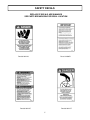
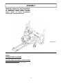
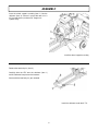
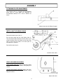
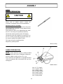
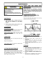
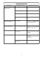
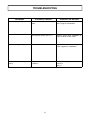
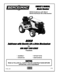
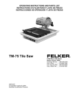
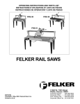
OWNER’S MANUAL
Model Number
700360--2
700360
Berco
Prestige Two Stage 48" Snowblower
For
ALL TERRAIN VEHICLES
* ASSEMBLY
* REPAIR PARTS
* OPERATION
* MAINTENANCE
CAUTION:
READ & FOLLOW ALL SAFETY RULES & INSTRUCTIONS BEFORE
OPERATING YOUR EQUIPMENT
104745
1
H-08
WARRANTY
LIMITED ONE YEAR ON NORTHEAST A.T.V. SNOWBLOWER
Snowblower Warranty:
For one year from date of purchase, BERCOMAC will repair or replace free of charge at BERCOMAC option, any
parts which are defective as a result of defective material or faulty workmanship.
Warranty service is available by returning the "Northeast" snowblower to the authorized dealers.
COMMERCIAL OR RENTAL USE:
Warranty on BERCO Northeast snowblower used for commercial or rental purposes is limited to 90 days.
This warranty does NOT cover:
* Wear items, such as shear bolts and belts
* Repairs due to customer abuse or neglect
* Pre-delivery set-up
* In home service
Engine Warranty:
Warranty for the Kohler engine is two years and is directly offered by Kohler.
Warranty service is available by returning the Kohler engine to the authorized dealers.
For information: Tel: 1-800-544-2444
BERCOMAC Limitée
92 Fortin N, Adstock (Québec) Canada, G0N 1S0
2
TABLE OF CONTENTS
PAGE
INTRODUCTION ......................................................................................................................................................
2
SAFETY PRECAUTIONS ........................................................................................................................................
3
SAFETY DECALS ....................................................................................................................................................
5
ASSEMBLY
Step 1: Bracket Installation .......................................................................................................................
Step 2: Snowblower Preparation ..............................................................................................................
Attaching Plate Adjustment ..........................................................................................................
Installing Winch Cable .................................................................................................................
Verify Skid Shoe Adjustment .......................................................................................................
Step 3: Engine Preparation .......................................................................................................................
Saddle Preparation ......................................................................................................................
6
7
9
9
9
10
10
OPERATION
Operating the Snowblower ........................................................................................................................
Electric Controls ..........................................................................................................................................
Removing Snow .........................................................................................................................................
11
11
11
MAINTENANCE
Maintenance ...............................................................................................................................................
Adjustments ................................................................................................................................................
Lubrication ...................................................................................................................................................
Cutting Edge Maintenance ........................................................................................................................
Auger and Fan Shear Bolt Replacement ..................................................................................................
Dismounting the Snowblower ....................................................................................................................
Storage ........................................................................................................................................................
12
12
12
12
12
12
12
BELT REPLACEMENT & ADJUSTMENTS ...........................................................................................................
13
TROUBLESHOOTING .............................................................................................................................................
14
PARTS BREAKDOWN AND PARTS LIST
Rotation System with Chute ......................................................................................................................
Saddle Assembly ........................................................................................................................................
Snowblower ................................................................................................................................................
Subframe .....................................................................................................................................................
16
18
20
24
TORQUE SPECIFICATION TABLE .......................................................................................................................
27
1
INTRODUCTION
TO THE PURCHASER
This new attachment was carefully designed to give years of dependable service. This manual has been provided to
assist in the safe operation and servicing of your attachment.
NOTE: All photographs and illustrations in the manual may not necessarily depict the actual models or attachment, but
are intended for reference only and are based on the latest product information available at the time of publication.
Familiarize yourself fully with the safety recommendations and operating procedures before putting the machine to use.
Carefully read, understand and follow these recommendations and insist that they be followed by those who will use
this attachment.
THIS SAFETY ALERT SYMBOL IDENTIFIES AN IMPORTANT SAFETY MESSAGE IN THIS MANUAL
THAT HELPS YOU AND OTHERS AVOID PERSONAL INJURY OR EVEN DEATH. DANGER,
WARNING, AND CAUTION ARE SIGNAL WORDS USED TO IDENTIFY THE LEVEL OF HAZARD.
HOWEVER, REGARDLESS OF THE HAZARD, BE EXTREMELY CAREFUL.
DANGER: Signals an extreme hazard that will cause serious injury or death if recommended precautions are
not followed.
WARNING: Signals a hazard that may cause serious injury or death if the recommended precautions are not
followed.
CAUTION: Signals a hazard that may cause minor or moderate injury if the recommended precautions are not
followed.
Record your attachment serial number and purchase date in the section reserved below. Your dealer requires this
information to give you prompt, efficient service when ordering replacement parts. Use only genuine parts when
replacements are required.
If warranty repairs are required please present this registration booklet and original sales invoice to your selling dealer
for warranty service.
This manual should be kept for future reference.
Please check if you have received all the parts for your kit with the list of the
bag and the list of the box.
SERIAL NUMBER :
___________________________
PURCHASE DATE :
___________________________
In this manual, right and left sides are determined by sitting on the A.T.V. seat facing forward.
In this manual, "attachment" means accessories that you install on the A.T.V. such as a snowblower.
2
SAFETY PRECAUTIONS
Careful operation is your best insurance against an accident. Read this section carefully before operating the A.T.V.
and snowblower. This snowblower is capable of amputating hands and feet and throwing objects. Failure to observe
the following safety instructions could result in serious injury. All operators, no matter how experienced they may be,
should read this and other manuals related to the A.T.V. and attachments before operating. It is the owner's legal
obligation to instruct all operators in safe operation of the snowblower.
e) When practical, remove gas-powered equipment
from the truck or trailer and refuel it on the
ground. If this is not possible, then refuel such
equipment on a trailer with a portable container,
rather than from a gasoline dispenser nozzle.
f) Keep the nozzle in contact with the rim of the
fuel tank or container opening at all times, until
refueling is complete. Do not use a nozzle lockopen device.
g) Replace fuel cap securely and wipe up spilled
fuel.
h) If fuel is spilled on clothing, change clothing
immediately.
TRAINING:
This symbol, "Safety Alert Symbol", is used
throughout this manual and on the
snowblower’s safety labels to warn of the
possibility of serious injury. Please take special
care in reading and understanding the safety
precautions before operating the snowblower or
the A.T.V.
1. Read this owner's manual carefully. Be thoroughly
familiar with the controls and proper use of the
A.T.V. and snowblower. Know how to stop the unit
and disengage the controls quickly.
5. Adjust the height of the snowblower to clear gravel or
crushed rock surface. This is done by adjusting the
skid shoes.
2. Never allow children to operate snowblower nor the
A.T.V. Never allow adults to operate snowblower nor
the A.T.V. without proper instructions.
6. Never attempt to make any adjustments while the
engine (motor) is running (except when specifically
recommended by manufacturer).
3. No one should operate the A.T.V. nor the
snowblower while intoxicated or while taking
medication that impairs the senses or reactions.
7. Let engine (motor) of the A.T.V. and snowblower
adjust to outdoor temperatures before starting to
clear snow.
4. Keep the area of operation clear of all persons,
particularly small children and pets.
8. Always wear safety glasses or eye shields during
operation or while performing an adjustment or
repair to protect eyes from foreign objects that may
be thrown from the machine.
PREPARATION:
1. Thoroughly inspect the area where the
snowblower is to be used and remove door mats,
all foreign objects and the like.
9. Never modify the snowblower or any part
without the written consent from the
manufacturer.
2. Disengage all clutches and shift into neutral before
starting engine.
3. Do not operate the snowblower without wearing
adequate winter outer garments. Avoid loose fitting
clothing that can get caught in moving parts. Wear
footwear that will improve footing on slippery
surfaces.
OPERATION:
4. Handle fuel with care, it is highly flammable.
a) Use approved fuel container.
b) Never add fuel to a running engine or hot engine.
c) Fill fuel tank outdoors with extreme care. Never
fill fuel tank indoors.
d) Never fill containers inside a vehicle, or on a
truck or a trailer bed with a plastic liner.
Always place containers on the ground, away
from your vehicle, before filling.
2. Exercise extreme caution when operating on or
crossing gravel drives, walks or roads. Stay alert for
hidden hazards or traffic.
1. Do not put hands or feet near or under rotating
parts. Keep clear of the discharge opening at all
times.
3. After striking a foreign object, stop the engine
(motor), disconnect the wire from the spark plug(s)
and keep wire away to prevent accidental starting.
Thoroughly inspect the snowblower for any damage
and repair damage before restarting and operating
the snowblower.
3
SAFETY PRECAUTIONS
4. If the unit should start to vibrate abnormally, stop the
engine (motor) and check immediately for the cause.
Vibration is generally a warning of trouble.
16.Use only accessories approved by the
manufacturer of the snowblower (such as wheel
chains, and the like).
5. Stop the engine (motor) whenever you leave the
operating position, before unclogging the impeller/
collector housing or discharge chute, and when
making repairs, adjustments or inspections.
17.Never operate the snowblower without good
visibility or light.
CLEARING A CLOGGED DISCHARGE CHUTE:
Hand contact with the rotating impeller inside the
discharge chute is the most common cause of injury
associated with snowblowers. Never use your hand to
clean out the discharge chute.
6) Take all possible precautions when leaving the
machine unattended. Disengage the power take-off,
lower the attachment, set the parking brake, stop the
engine and remove the key.
To clear the chute:
1. Lower snowblower to the ground and set parking
brake.
2. SHUT THE ENGINE OFF & REMOVE KEY!
3. Wait 10 seconds to be sure the all moving parts
such as the impeller blades have stopped moving.
4. Disconnect wire from the spark plug(s) and keep
wire away to prevent accidental starting.
5. Always use a clean-out tool of at least 36” in
length, NOT YOUR HANDS.
7. When cleaning, unclogging, repairing or inspecting,
the snowblower & A.T.V. make certain the collector/
impeller and all moving parts have stopped.
Disconnect wire from the spark plug(s) and keep wire
away to prevent accidental starting.
8. Do not run the engine indoors, except when starting
the engine and for transporting the snowblower in or
out of the building. Do not operate or let motor run in
a storage area without ventilation because gas
contains carbon monoxide which is odourless,
colorless and can cause death.
MAINTENANCE AND STORAGE
1. Check shear bolts, engine mounting bolts, and
other bolts at frequent intervals for proper
tightness to be sure the snowblower is in safe
working condition.
2. Never store the machine with fuel in the fuel tank
inside a building where ignition sources are
present such as hot water and space heaters,
clothes dryers, and the like. Allow the engine to
cool before storing in any enclosure.
3. Always refer to the owner’s manual for the motor
and snowblower when they are to be stored for
an extended period.
4. Maintain or replace safety and instruction labels,
as necessary.
5. Run the snowblower a few minutes after throwing
snow to prevent freeze-up of the rotating parts
such as collector/impeller.
9. Do not clear snow across the face of slopes; go up
and down. Exercise extreme caution when
changing direction on slopes. Do not attempt to
clear steep slopes.
10.Never operate the snowblower without proper
guards, plates, or other safety protective devices
in place.
11.Never direct discharge at bystanders or operate
the
snowblower
near
glass
enclosures,
automobiles, window wells, drop-offs, and the like
without proper adjustment of the snow discharge
angle. Never allow anyone including children and
pets in the clearance area.
12.Do not overload the machine capacity by
attempting to clear snow at too fast a rate. Let the
snowblower ingest snow at its own rate.
WHENEVER YOU SEE THIS SYMBOL
13.Never operate the snowblower at high transport
speeds on slippery surfaces. Look behind and use
care when backing.
14.Do not carry passengers.
IT MEANS:
WARNING!
BECOME ALERT !
YOUR SAFETY IS INVOLVED!
15.Disengage power to the collector/impeller to stop
all rotating parts when the snowblower is
transported or not in use.
4
SAFETY DECALS
REPLACE IF DECALS ARE DAMAGED
SEE PARTS BREAKDOWN FOR DECAL LOCATION
Decal # 102126
Decal # 103951
Decal # 102125
Decal # 102127
5
ASSEMBLY
IMPORTANT: TORQUE ALL BOLTS ACCORDING
TO TORQUE SPECIFICATION TABLE (SEE TABLE
OF CONTENTS) WHEN STATED: TIGHTEN
FIRMLY. REFER TO PARTS BREAKDOWN
SECTION FOR PART IDENTIFICATION.
Overall view
STEP 1
BRACKET INSTALLATION:
You must obtain the brackets available through
‘’BOMBARDIER’’ or ‘’WARN’’.
Please see instructions included with brackets.
6
ASSEMBLY
STEP 2
SNOWBLOWER PREPARATION:
Remove the two 7/16 x 2’’ hex bolts (item 1), the right
and left spring links (item 2).
Remove bolts and spring links
Align the subframe (item 1) under the snowblower and
hold in place with the bolts (item 2) you removed and
the two 7/16 x 1 1/2’’ hex bolts (item 3).
Install the right and left spring links (item 8) on the
inside of frame and under the two attaching flat bars as
shown. Secure with the four 7/16’’ nylon insert lock nuts
you removed.
Tighten firmly.
Add a 5/16’’ hex. nut (item 4) on each eye bolt (item 5).
Tighten about half way down.
Insert the spring (item 7) into the spring link (item 8) as
shown.
Hook the other end of spring into the eye bolt and insert
it into the hole (item 9) .
Add a 5/16’’ nylon insert lock nut (item 10) and tighten
to apply tension on the spring.
Assemble subframe to snowblower
7
ASSEMBLY
Insert the wheel support assembly (item 1) into the
subframe (item 2). Secure in place with two 3/8 x 2
1/2’’ hex bolt (item 3) and two 3/8’’ flange nuts.
Tighten firmly.
Install the wheel support assembly
Remove the two lock pins (item 2).
Carefully drive the ATV over the subframe (item 1)
and lift subframe into place on the brackets.
Secure with the two lock pins you removed.
Install the subframe under the A.T.V.
8
ASSEMBLY
ATTACHING PLATE ADJUSTMENT:
This subframe (item 1) is equipped with two attaching
plates (item 2). These plates are adjustable to
accommodate different A.T.V.s with or without cat
tracks.
Adjust these plates for different lengths
INSTALLING THE WINCH CABLE
Remove the two hair pins (item 1).
Pull the winch hook over the small pulley (item 2).
Then thread the hook inside the lift lever (item 3) and
under the pulley (item 4) and back up over the pulley
(item 2) and insert the hook in the hole (item 5)
intended for this purpose.
Reinstall the two hair pins.
Install the winch cable
VERIFY SKID SHOE ADJUSTMENT:
LEVEL PAVED SURFACE: Adjust skid shoes to allow
3/16" to 1/4" clearance (A) between cutting edge and
surface.
UNEVEN OR GRAVEL SURFACE: Adjust skid shoes
to allow 1/2" to 5/8" clearance (A) between cutting
edge and surface.
Adjust skid shoes
9
ASSEMBLY
STEP 3
ENGINE PREPARATION:
CAUTION
Oil must be added to this motor.
Please refer to motor’s owner’s manual for
instructions and proper winter oil recommendations.
Connecting the wire assembly:
The kit is equipped with a connector which will permit
you to remove the snowblower quickly without having
to remove the wiring.
Place and tie the wires in an appropriate place under
the A.T.V. since they will stay there permanently.
Connect the red wire (positive) to the ATV battery.
Connect the black wire (negative) on a bolt that is on
the A.T.V. frame (scrape away any paint to make sure
the contact is good) and retighten the bolt.
Fill the gas tank with unleaded gasoline.
Wipe off any spilled gasoline.
Wire assembly
SADDLE PREPARATION:
NOTE: All the electrical system is already installed
and connected to the various snowblower components.
Place the saddle assembly on the A.T.V. seat.
Place and tie the wire protector in an appropriate place
so the wire protector does not interfere with any hot or
moving parts
Saddle controls
Item
Item
Item
Item
Item
Item
Item
10
1: P.T.O. Switch
2: Ignition Switch
3: Switch (chute)
4: Throttle Control
5: Switch (chute)
6: Choke Control
7: Safety Switch
OPERATION
OPERATING THE SNOWBLOWER
WARNING
You must be sitting on the saddle in order to
start the snowblower engine.
Read the A.T.V.’s owner’s manual carefully. Be
thoroughly familiar with the controls & proper
use of the attachment. Know how to stop the unit
& disengage the controls quickly.
a) Make sure the snowblower is clear of snow
before engaging the snowblower.
b) Make sure that the auger and fan operate freely.
c) Start the snowblower engine.
d) Before engaging the snowblower drive, always
have the engine running at medium R.P.M.
e) Operate the snowblower at maximum engine
R.P.M.
IMPORTANT: USE FULL ENGINE R.P.M. WHEN
REMOVING WET, STICKY SNOW. LOW R.P.M.
POWER WILL TEND TO PLUG THE CHUTE.
WARNING
ELECTRIC CONTROLS
-Do not attempt to clear plugged chute, auger or
fan of snow while the snowblower's engine is
running.
-Disengage snowblower.
-Lower snowblower onto ground.
-Set the parking brake.
-Stop engine, remove the ignition key, disconnect
the wire from spark plug(s) and keep away from
spark plug(s) to prevent accidental starting.
-Make sure all moving parts have stopped.
-Do not use hand to unplug chute.
-Use a 36’’ (924 mm.) minimum length stick or
board.
See page 10 for identification of the saddle
controls.
RAISING AND LOWERING THE SNOWBLOWER:
Use the winch switch control to raise and lower the
snowblower.
TURNING THE CHUTE AND DEFLECTOR:
Use the switches on the saddle to turn the chute and
to raise or lower the deflector.
ENGAGING
AND
DISENGAGING
THE
SNOWBLOWER:
Engage the snowblower when the engine is running
at medium R.P.M. by pulling the P.T.O. switch.
WARNING
TO PREVENT INJURIES AND FOR MORE
TRACTION WHEN USING SNOWBLOWER:
-Do not drive faster than 3 km/hr (2 m/hr) with
snowblower on the ground.
-Do not drive faster than 10 km/hr (6 m/hr) with
the snowblower in raised position.
-Do not operate on a slope greater than 10°.
-A.T.V. manufacturer approved tire chains are
required.
REMOVING SNOW
When removing snow, do not use the snowblower as
a dozer blade to push snow. Allow snowblower to
ingest snow at its own speed. If the speed of your
A.T.V. is too fast, the snowblower may become
overloaded and plug. For best results, raise the
snowblower and remove a top layer of snow. A
second pass with the snowblower will remove the
remaining snow.
11
MAINTENANCE
AUGER
AND
REPLACEMENT
WARNING
FAN
SHEAR
BOLT
TO PREVENT INJURIES:
Stop the snowblower motor.
Apply parking brake.
Remove the ignition key.
Disconnect the wire from the spark plug(s) and
keep away from spark plug(s) to prevent accidental
starting.
*Shear bolts are to be considered a preventive
measure and not a assured protection. Operator
vigilance is required. Thoroughly inspect the areas
where the snowblower is to be used and remove all
foreign objects.
MAINTENANCE
The use of any other shear bolt will not insure any
protection and may void the warranty.
To avoid damage to the snowblower:
Use only the original shear bolts (grooved bolts).
#104000 in bags of 10 for both sections of auger.
#103999 in bags of 10 for the fan.
a) Check mounting bolts at frequent intervals for
proper tightness in order to prevent costly repairs.
Make sure your snowblower is in safe working
condition.
b) Provide adequate blocking before working under
the snowblower when in raised position.
ADJUSTMENTS
SKID SHOE ADJUSTMENT:
Level Paved Surface: Adjust skid shoes to allow 3/16" to
1/4" clearance between cutting edge and surface.
Uneven or Gravel Surface: Adjust skid shoes to allow
1/2" to 5/8" clearance between cutting edge and
surface.
DISMOUNTING THE SNOWBLOWER:
a) Unplug connector that unites the A.T.V. to the
motor.
b) Remove the winch hook & cable from the
snowblower.
c) Remove the lock pins from the rear of the
subframe. Lower the subframe to the ground.
Reinstall the lock pins in the holes.
d) Carefully back up the A.T.V. from over the
subframe.
LUBRICATION
Grease the wheel axles, the fork pivots after every
sixteen hours of use.
Apply oil at all pivot points.
Chute Rotation System: Oil chute base, rotation worm
every sixteen hours of operation.
STORAGE
a) Clean snowblower and subframe thoroughly and
repaint all parts from which paint has worn.
b) List the replacement parts that will be needed
before the next season.
c) Follow the instructions in the lubrication section
d) Store the snowblower and the subframe in a dry
place.
e) Concerning the snowblower engine, follow the
instructions in the engine owner’s manual.
CUTTING EDGE MAINTENANCE
Verify from time to time the wearing on the cutting
edge to make sure you do not wear out the base of
the snowblower’s chassis. This cutting edge is
reversible. Unscrew the bolts and turn the cutting
edge. Tighten the bolts securely.
12
BELT REPLACEMENT & ADJUSTMENTS
BELT REPLACEMENT:
TIMING BELT ADJUSTMENT:
For belt part numbers, refer to snowblower parts
breakdown section for parts identification
Snowblower must be detached & disconnected
from the A.T.V. to replace belts
V-Belt:
a) Remove the belt guard (item 1)
To obtain the right tension on the timing belt, make
sure that the four nuts (item 7) are loosened. Tighten
the two nuts (item 8) needed to apply tension to the
belt until the three spring washers (item 9) are
completely compressed. Tighten the four nuts (item
7).
NOTE: To help avoid the belt from breaking, it is
preferable to put less tension on the belt than too
much tension.
Before re-installing snowblower to ATV, turn the
auger by hand a few turns and verify that the timing
belt does not run off to the side of the sprocket the
belt does move, re-align by adjusting the nuts (item 7
and / or item 3).
After installing the snowblower to ATV, let
snowblower run for a minute, turn everything off and
re-inspect the belt. If needed re-align by adjusting
nuts.
b) Remove the 7/16 x 5 1/2’’ hex bolt (item 2) from
the clutch support.
c) Disconnect the wire from electric clutch.
d) Remove the gas tank from the support. (Put on
the ground to avoid any spills).
e) Turn the snowblower face down (engine on top).
f)
Remove the six nuts (item 3) and bolts from the
reduction plate (item 4).
g) Remove the reduction plate.
h) Unhook the spring (item 5) from the slot on the
tension arm (item 6) and remove the tension arm.
i)
Replace the V-belt.
j)
Re-install parts by repeating steps backwards.
(Make sure the pin on the reduction plate is
inserted in the tube on the tension arm).
Timing Belt:
a) Remove the gas tank from the support. (Put on
the ground to avoid any spills).
b) Turn the snowblower face down (engine on top).
c) Loosen the two nuts (item 7) on each side and
the two nuts (item 8) needed to apply tension to
the belt.
d) Remove the six nuts (item 3) and bolts from the
reduction plate (item 4)
e) Remove the reduction plate
f) Unhook the spring (item 5) from the slot on the
tension arm (item 6) and remove the tension arm.
g) Replace the timing belt. (Make sure to replace the
V-belt on the V-pulley).
h) Re-install parts by repeating steps backwards.
(Make sure the pin on the reduction plate is
inserted in the tube on the tension arm).
IMPORTANT:
Make sure the notches of the belt are well
inserted into the those of the pulley.
CAUTION
Never use the snowblower without the belt guard.
13
TROUBLESHOOTING
PROBLEM
Snowblower vibrates
abnormally noisy.
POSSIBLE CAUSES
or
CORRECTIVE ACTION
is Damaged pulley.
Replace pulley.
Damaged bearing.
Replace bearing.
Damaged fan.
Dismount & repair or replace fan.
One or both sections of the auger is Replace one or both sections of
bent.
auger.
One or both sections of the Shear bolt broken.
auger have stopped turning.
Replace shear bolt (for identification,
see Parts List "Snowblower"). Also
see "Maintenance" section.
Snowblower stopped turning.
The belts are damaged or snapped.
Check & replace damaged belts (see
instructions
in
section:Belt
replacement & adjustments.
Belt is worn at a specific point.
Snowblower was
already plugged.
Chute rotation is difficult.
Dirt or ice may be underneath chute.
Clean the base of chute & the
rotation ring.
Lubricate chute inside & out and the
rotation worm.
The base of the chute may be
damaged or bent.
Replace defective parts.
engaged
14
when Make sure auger & fan are not
plugged or frozen before engaging
snowblower.
TROUBLESHOOTING
PROBLEM
POSSIBLE CAUSES
The chute plugs easily.
Snowblower engine is turning too Always have engine at full R.P.M.
slowly.
when using the snowblower.
Snowblower digs into ground.
Snowblower
evenly.
does
not
CORRECTIVE ACTION
Advancing too quickly with A.T.V.
Reduce speed. Allow snowblower to
ingest snow at its own speed.
Ground is not frozen or too soft.
Adjust skid shoes lower so they may
better support the snowblower.
raise Tire pressure uneven from one side Verify and adjust snowblower tire
to another.
pressure:
50 p.s.i.
15
PARTS BREAKDOWN / NOMENCLATURE DES PIÈCES
ROTATION SYSTEM WITH CHUTE
SYSTÈME DE ROTATION AVEC GOULOTTE
16
PARTS LIST / LISTE DES PIÈCES
Ref.
Réf.
English description
Description française
Qty.
Qté.
Part #
Pièce #
1 Chute
Goulotte
1
103936
2 Bracket
Support
1
103971
3 Reinforcement plate
Plaque de renforcement
1
103972
4 Spacer
Espaceur
3
103368
5 Rotation ring
Anneau de rotation
1
103974
6 Hex. bolt 1/4" n.c. x 1 1/2"
Boulon hex. 1/4" n.c. x 1 1/2"
3
O/L
7 Spacer
Espaceur
6
103361
8 Bracket
Support
1
103375
9 Electric motor
Moteur électrique
2
103378
10 Lever
Levier
1
103365
11 Oil lite bushing
Coussinet imprégné d'huile
1
103362
12 Plate
Plaque
1
103363
13 Arm
Bras
1
103364
14 Nylon flat washer 11/32"
Rondelle plate de nylon 11/32"
2
102009
15 Nylon flat washer 7/16"
Rondelle plate de nylon 7/16"
2
102011
16 Carriage bolt 1/4" n.c. x 1"
Boulon à carrosserie 1/4" n.c. x 1"
2
O/L
17 Rotation ring
Anneau de rotation
1
103943
18 Hand guard
Fourche protectrice
1
102012
19 Hex. bolt 1/4" n.c. x 3/4"
Boulon hex. 1/4" n.c. x 3/4"
4
O/L
20 Nylon insert lock nut 5/16" n.c.
Écrou à garniture de nylon 5/16" n.c.
2
O/L
21 Hex. bolt 1/4" n.c. x 1 3/4"
Boulon hex. 1/4" n.c. x 1 3/4"
3
O/L
22 Nylon insert lock nut 1/4" n.c. (thin)
Écrou à garniture de nylon 1/4" n.c.(mince)
15
O/L
23 Flat washer 5/16" hole
Rondelle plate 5/16" trou
3
O/L
24 Machine screw T.H. 1/4" n.c. x 1/2"
Vis mécanique T.H. 1/4" n.c. x 1/2"
3
O/L
25 Carriage bolt 5/16" n.c. x 3/4"
Boulon à carrosserie 5/16" n.c. x 3/4"
2
O/L
26 Flange nut 1/4" n.c.
Écrou à bride 1/4" n.c.
4
O/L
27 Hex. bolt 1/4" n.c. x 1"
Boulon hex. 1/4" n.c. x 1"
4
O/L
28 Danger decal
Décalque danger
1
102127
O/L= Obtain locally / Obtenir localement
17
PARTS BREAKDOWN / NOMENCLATURE DES PIÈCES
SADDLE ASSEMBLY / SELLE ASSEMBLÉE
18
PARTS LIST / LISTE DES PIÈCES
Ref.
Réf.
English description
Description française
Qty.
Qté.
Part #
Pièce #
1 Seat cover
Couvre-siège
1
103987
2 Control board
Tableau de contrôle
1
104011
3 Switch support
Support de commutateur
1
104012
4 Safety switch ass'y
Commutateur de sécurité ass'é
1
104014
5 Ignition switch
Commutateur d'ignition
1
104015
6 P.T.O. switch
Commutateur de p.d.f.
1
104016
7 Switch
Commutateur
2
103381
8 Rubber boot
Capuchon de caoutchouc
2
103379
9 Throttle control
Contrôle de l' accélérateur
1
104008
10 Choke control
Contrôle de l'étrangleur
1
104009
11 Wire assembly
Fil assemblé
1
104017
12 Wire assembly
Fil assemblé
1
104018
13 Wire assembly (Incl. 103382)
Fils assemblés (Incl. 103382)
1
104295
14 Pop-rivet 3/16" no AD-66BS
Rivet pop 3/16 no.AD-66BS
4
O/L
15 Carriage bolt 5/16" n.c. x 1"
Boulon à carrosserie 5/16" n.c. x 1"
2
O/L
16 Flange nut 5/16" n.c.
Écrou à bride 5/16" n.c.
2
O/L
17 Shim
Cale
1
104013
18 Breaker
Disjoncteur
1
103382
19 Tie wrap 8"
Attache de nylon 8"
12
O/L
O/L= Obtain locally / Obtenir localement
19
PARTS BREAKDOWN / NOMENCLATURE DES PIÈCES
SNOWBLOWER / SOUFFLEUSE
20
PARTS LIST / LISTE DES PIÈCES
Ref.
Réf.
English description
Description française
Qty.
Qté.
Part #
Pièce #
1 Frame 48"
Châssis 48"
1
103954
2 Gear box 48"
Boîte d'engrenage 48"
1
103948
3 Reduction plate
Plaque de réduction
1
103959
4 Shaft
Arbre
1
103961
5 Key 1/4" x 1/4" x 2 31/32
Clé 1/4" x 1/4" x 2 31/32
1
103962
6 Attaching flat bar
Fer plat d'attache
2
103966
7 Reduction box
Boîte de réduction
1
103960
8 Bearing with set screw
Roulement à billes avec vis à pression
5
102755
9 Flangette
Flangette
6
102213
10 Spacer
Douille d'espacement
1
103997
11 Sprocket with set screw
Pignon avec vis à pression
1
103743
12 Sprocket with set screw
Pignon avec vis à pression
1
103741
13 Engine support
Support de moteur
1
103970
14 Carriage bolt 5/16" n.c. x 3/4"
Boulon à carrosserie 5/16" n.c. x 3/4"
28
O/L
15 Flange nut 5/16" n.c.
Écrou à bride 5/16" n.c.
24
O/L
16 Tension arm
Bras de tension
1
103985
17 V pulley
Poulie en V
1
103739
18 Flat pulley
Poulie plate
1
102839
19 Electric clutch
Embrayage électrique
1
103998
20 Engine CH-23 (Kohler)
Moteur CH-23 (Koler)
1
104003
21 Clutch spacer
Espaceur d'embrayage
1
103975
22 Flange washer
Rondelle à bride
1
103976
23 Clutch support
Support d'embrayage
1
103980
24 Belt guard
Garde-courroie
1
103979
25 Key 1/4" x 1/4" x 2"
Clé 1/4" x 1/4" x 2"
2
102922
26 Auger 48" left
Vis 48" gauche
1
103955
27 Auger 48" right
Vis 48" droite
1
103956
28 Rotation bushing
Coussinet de rotation
4
103946
29 Hex. bolt 3/8" n.c. x 3/4"
Boulon hex. 3/8" n.c. x 3/4"
4
O/L
30 Flangette
Flangette
2
102680
O/L= Obtain locally / Obtenir localement
21
PARTS LIST / LISTE DES PIÈCES
Ref.
Réf.
English description
Description française
Qty.
Qté.
Part #
Pièce #
31 Flange nut 3/8" n.c.
Écrou à bride 3/8" n.c.
12
O/L
32 Fan
Éventail
1
103932
33 Shear plate
Plaque de cisaillement
1
103933
34 Shear bolt / N.I.L.N. (auger) pkg-10
Boulon de séc. / É.G.N. (vis) pqt-10
2
104000
35 Shear bolt / N.I.L.N. (fan) pkg-10
Boulon de séc./ É.G.N. (éven.) pqt-10
1
103999
36 Oil lite bushing
Coussinet imprégné d'huile
2
102784
37 Cutting edge 48"
Racloir 48"
1
103187
38 Stover lock nut 5/16" n.c.
Écrou de blocage 5/16" n.c.
6
O/L
39 Hex. bolt 5/16" n.c. x 2 1/4" GR8
Boulon hex. 5/16" n.c. x 2 1/4" GR8
1
O/L
40 Nylon insert lock nut 5/16" n.c.
Écrou à garniture de nylon 5/16" n.c.
3
O/L
41 Gear box support
Support de boîte d'engrenage
1
103940
42 Hex. bolt 5/16" n.c. x 3/4"
Boulon hex. 5/16" n.c. x 3/4"
2
O/L
43 Left drift cutter
Couteau à neige gauche
1
102821
44 Right drift cutter
Couteau à neige droit
1
102822
45 Machine screw T.H. 1/4" n.c. x 1/2"
Vis mécanique T.H. 1/4" n.c. x 1/2"
6
O/L
46 Flange nut 1/4" n.c.
Écrou à bride 1/4" n.c.
6
O/L
47 Hex. bolt 7/16" n.c. x 1 1/4"
Boulon hex. 7/16" n.c. x 1 1/4"
2
O/L
48 Nylon insert lock nut 7/16" n.c.
Écrou à garniture de nylon 7/16" n.c.
2
O/L
49 Cotter pin 3/16" x 1"
Goupille fendue 3/16" x 1"
1
O/L
50 Spring
Ressort
1
102304
51 Hex. bolt 3/8" n.c. x 1 1/2"
Boulon hex. 3/8" n.c. 1 1/2"
4
O/L
52 Skid shoe
Patin
2
103188
53 Hex. bolt 3/8" n.c. x 1 3/4"
Boulon hex. 3/8" n.c. x 1 3/4"
1
O/L
54 Nylon insert lock nut 3/8" n.c.
Écrou à garniture de nylon 3/8" n.c.
1
O/L
55 Tank support
Support de réservoir
1
103963
56 Gasoline tank assembly
Réservoir d'essence assemblé
1
104005
57 Timing belt 600-8MT-30
Courroie synchronisée 600-8MT-30
1
104004
58 V-Belt , A-40
Courroie en V , A-40
1
102999
59 Heat shield
Pare-chaleur
1
104621
60 Flat washer 1/2" hole
Rondelle plate 1/2" trou
2
O/L
O/L= Obtain locally / Obtenir localement
22
PARTS LIST / LISTE DES PIÈCES
Ref.
Réf.
English description
Description française
Qty.
Qté.
Part #
Pièce #
60 Flat washer 1/2" hole
Rondelle plate 1/2" trou
2
O/L
61 Hex. bolt 7/16" n.c. x 5 1/2"
Boulon hex. 7/16" n.c. x 5 1/2"
1
O/L
62 Hex. bolt 7/16" n.f. x 1 1/2"
Boulon hex. 7/16" n.f. x 1 1/2"
1
O/L
63 Hex. socket set screw 5/16" n.c. x 5/16" Vis à pression hex. 5/16" n.c. x 5/16"
2
O/L
64 Wing nut 5/16" n.c.
Écrou oreilles 5/16" n.c.
2
O/L
65 Tension bar
Barre de tension
1
103995
66 Spring washer
Rondelle à ressort
6
104007
67 Flat washer 3/8" hole
Rondelle plate 3/8" trou
6
O/L
68 Carriage bolt 5/16" n.c. x 2 1/4"
Boulon à carrosserie 5/16" n.c. x 2 1/4"
2
O/L
69 Danger decal
Décalque danger
1
102126
70 Shear bolt decal
Décalque boulon de sécurité
1
103951
71 Carriage bolt 3/8" n.c. x 3/4"
Boulon à carrosserie 3/8" n.c. x 3/4"
4
O/L
72 Warning decal
Décalque attention
1
102125
73 Serial number
Numéro de série
1
REF
74 Berco decal
Décalque Berco
1
102471
75 Machine screw P.H. #10 x 32 x 1 1/2"
Vis mécanique P.H. #10 x 32 x 1 1/2"
2
O/L
76 Lock washer 7/16"
Rondelle de blocage 7/16"
2
O/L
O/L= Obtain locally / Obtenir localement
23
PARTS BREAKDOWN / NOMENCLATURE DES PIÈCES
SUBFRAME / SOUS-CHÂSSIS
24
PARTS LIST / LISTE DES PIÈCES
Ref.
Réf.
English description
Description française
Qty.
Qté.
Part #
Pièce #
1 Subframe
Sous-châssis
1
103989
2 Push frame
Châssis de poussée
1
103982
3 Wheel support
Support de roue
1
103984
4 Pin
Goupille
1
103958
5 Hair pin 3mm
Goupille à ressort 3mm
3
102617
6 Lift lever
Levier de relevage
1
103967
7 Lift link
Lien de relevage
1
103983
8 Wheel fork
Fourche de roue
1
103986
9 Left spring link
Lien du ressort gauche
1
103977
10 Right spring link
Lien du ressort droit
1
103978
11 Pin
Goupille
1
103991
12 Attaching plate
Plaque d'attache
2
103992
13 Pulley
Poulie
2
103993
14 Pin
Goupille
1
103996
15 Nylon bushing
Coussinet en nylon
4
103087
16 Cotter pin 3/16" x 1-1/2"
Goupille fendue 3/16" x 1-1/2"
2
O/L
17 Grease fitting 1/4" n.f.
Graisseur 1/4" n.f.
2
O/L
18 Lock pin
Tige de verrouillage
2
103563
19 Hex. bolt 7/16" n.c. x 2"
Boulon hex. 7/16" n.c. x 2"
2
O/L
20 Nylon insert lock nut 7/16" n.c.
Écrou à garniture de nylon 7/16" n.c.
4
O/L
21 Rim & bearing
Jante & roulement
1
102687
22 Ball bearing
Roulement à billes
2
102688
23 Tire 280/250-4
Pneu 280/250-4
1
102674
24 Inner tube 250-4
Chambre à air 250-4
1
102675
25 Axle bolt & nut
Boulon essieu & écrou
1
102685
26 Sleeve
Douille
2
103276
27 Eye bolt
Boulon à oeillet
2
102087
28 Hex. bolt 7/16" n.c. x 1 1/2"
Boulon hex. 7/16" n.c. x 1 1/2"
2
O/L
29 Spring
Ressort
2
103073
30 Hex. bolt 3/8" n.c. x 2 1/2"
Boulon hex 3/8" n.c. x 2 1/2"
2
O/L
25
PARTS LIST / LISTE DES PIÈCES
Ref.
Réf.
English description
Description française
Qty.
Qté.
Part #
Pièce #
31 Flange nut 3/8" n.c.
Écrou à bride 3/8" n.c.
6
O/L
32 Nylon insert lock nut 5/16" n.c.
Écrou à garniture de nylon 5/16" n.c.
2
O/L
33 Hex. nut 5/16" n.c.
Écrou hex. 5/16" n.c.
2
O/L
34 Cotter pin 5/32" x 1 1/4"
Goupille fendue 5/32" x 1 1/4"
2
O/L
35 Hex. bolt 1/2" n.c. x 2 1/2"
Boulon hex. 1/2" n.c. x 2 1/2"
2
O/L
36 Nylon Insert lock Nut 1/2" n.c.
Écrou à garniture de nylon 1/2" n.c.
4
O/L
37 Hex. bolt 3/8" n.c. x 1"
Boulon hex. 3/8" n.c. x 1"
4
O/L
38 Hex. bolt 1/2" n.c. x 1 1/2"
Boulon hex. 1/2" n.c. x 1 1/2"
2
O/L
39 Cotter pin 5/32" x 1"
Goupille fendue 5/32" x 1"
2
O/L
40 Caster wheel assembly
Roue pivotante assemblée
2
104487
O/L= Obtain locally / Obtenir localement
26
TORQUE SPECIFICATION TABLE
GENERAL TORQUE SPECIFICATION TABLE
USE THE FOLLOWING TORQUES WHEN SPECIAL TORQUES ARE NOT GIVEN
NOTE: These values apply to fasteners as received from supplier, dry or when lubricated with normal oil. They do not apply if
special graphited or moly disulphide greases or other extreme pressure lubricants are used. This applies to both UNF and UNC
threads.
SEE Grade No.
BOLT HEAD
IDENTIFICATION
MARKS AS PER GRADE
NOTE MANUFACTURING
MARKS WILL VARY
BOLT SIZE
Inches
2
5
8*
TORQUE
TORQUE
TORQUE
POUNDS FEET
Millimetre
Min.
Max.
NEWTON-METERS
Min.
Max.
POUNDS FEET
Min.
NEWTON-METERS
POUNDS FEET
NEWTON-METERS
Max.
Min.
Max.
Min. Max.
Max.
Min. Max.
Max.
1/4"
6.35
5
6
6.8
8.13
9
11
12.2
14.9
12
15
16.3
30.3
5/16"
7.94
10
12
13.6
16.3
17
20.5
23.1
27.8
24
29
32.5
39.3
3/8"
9.53
20
23
27.1
31.2
35
42
47.5
57
45
54
61
73.2
7/16"
11.11
30
35
40.7
47.4
54
64
73.2
86.8
70
84
94.9
113.9
1/2"
12.7
45
52
61
70.5
80
96
108.5
130.2
110
132
149.2
179
9/16"
14.29
65
75
88.1
101.6
110
132
149.2
179
160
192
217
260.4
5/8"
15.88
95
105
128.7
142.3
150
180
203.4
244.1
220
264
298.3
358
3/4"
19.05
150
185
203.3
250.7
270
324
366.1
439.3
380
456
515.3
618.3
7/8"
22.23
160
200
216.8
271
400
480
542.4
650.9
600
720
813.6
976.3
25.4
250
300
338.8
406.5
580
696
786.5
943.8
900
1080
1220.4
1464.5
1"
*Thick nuts must be used with grade 8 bolts
METRIC BOLT TORQUE SPECIFICATIONS
Size Screw
Grade No.
Pitch (mm)
M6
4T
7T
8T
4T
7T
8T
4T
7T
8T
4T
7T
8T
4T
7T
8T
4T
7T
8T
4T
7T
8T
4T
7T
8T
1.00
M8
M10
M12
M14
M16
M18
M20
1.25
1.50
1.75
2.00
2.00
2.00
2.50
COARSE THREAD
Pounds Feet
Newton-Meters
3.6
5.8
7.2
7.2
17
20
20
34
38
28
51
57
49
81
96
67
116
129
88
150
175
108
186
213
-
5.8
9.4
10
14
22
26
25
40
46
34
59
66
56
93
109
77
130
145
100
168
194
130
205
249
4.9
7.9
9.8
9.8
23
27.1
27.1
46.1
51.5
37.9
69.1
77.2
66.4
109.8
130.1
90.8
157.2
174.8
119.2
203.3
237.1
146.3
252
288.6
27
7.9
12.7
13.6
- 19
29.8
35.2
33.9
54.2
62.3
46.1
79.9
89.4
75.9
- 126
- 147.7
- 104.3
- 176.2
- 196.5
- 136
- 227.6
- 262.9
- 176.2
- 277.8
- 337.4
Pitch (mm)
FINE THREAD
Pounds Feet
Newton-Meters
-
1.00
1.25
1.25
1.50
1.50
1.50
1.50
12
19
22
20
35
40
31
56
62
52
90
107
69
120
140
100
177
202
132
206
246
-
17
27
31
29
47
52
41
68
75
64
106
124
83
138
158
117
199
231
150
242
289
16.3
25.7
29.8
27.1
47.4
54.2
42
75.9
84
70.5
122
145
93.5
162.6
189.7
136
239.8
273.7
178.9
279.1
333.3
-
23
36.6
42
39.3
63.7
70.5
55.6
92.1
101.6
86.7
143.6
168
112.5
187
214.1
158.5
269.6
313
203.3
327.9
391.6