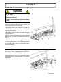
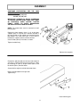
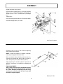
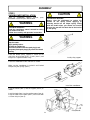
1
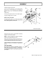
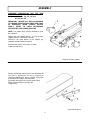
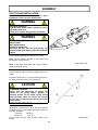
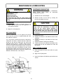
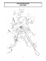
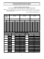
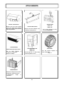
OWNER’S MANUAL
Model Number
700219-4 Deluxe subframe
BERCO
Deluxe Subframe
for
JOHN DEERE
SERIES 300, LX, GT, GX and GG-100
Tractors with Hydraulic Lift
* ASSEMBLY
* REPAIR PARTS
* OPERATION
* MAINTENANCE
CAUTION:
READ & FOLLOW ALL SAFETY RULES & INSTRUCTIONS BEFORE
OPERATING YOUR EQUIPMENT
106285_en
*106285*
1
L-10
LIMITED WARRANTY
Owner’s Responsibilities:
Conditions and Products Covered:
BERCOMAC guarantees any part of the product or accessory
manufactured by BERCOMAC and found in the reasonable
judgment of BERCOMAC to be defective in material and or
workmanship will be repaired or replaced by an authorized
dealer without charge up to our maximum labor rates and preestablished times. For replacement parts only standard ground
freight services are covered. This warranty extends to the
original retail purchaser only and is not transferable to any
subsequent purchasers.
BERCOMAC’s defective equipment or part must be returned
to an authorized dealer within the warranty period for repairs.
In the event that defective merchandise must be returned to
manufacturer for repairs, freight fees are prepaid and a written
authorization from BERCOMAC must be obtained by dealer
prior to the shipment. This warranty extends only to
equipment operated under normal conditions. To validate a
warranty claim, it is the user’s responsibility to maintain and
service the unit as specified in the owner’s manual or to have
the unit serviced at their dealer at their expense.
Warranty Period
(from date of the original retail purchase)
General Conditions:
• Residential use: 1 year
• Semi-commercial, professional or rental use: 90 days
Exceptions Noted Below; the following items are guaranteed
by the original manufacturer and have their own warranty,
conditions and limited time:
The sole liability of BERCOMAC with respect to this warranty
shall be strictly and exclusively repair and replacement as
mentioned herein. BERCOMAC shall not have any liability for
any other costs, loss or damage, including but not limited to,
any incidental or consequential loss or damage.
• Tire Chains: 90 days
• Engines: Will vary as per the manufacturer
Please refer to the engine manufacturer’s warranty
statement included with the unit. BERCOMAC is not
authorized to handle warranty adjustments on engines.
In particular, without being limited to, BERCOMAC shall have
no liability or responsibility for:
• Travel time, overtime, after hours time or other
extraordinary repair charges or relating to repairs and or
replacements outside of normal business hours.
• Rental of like or similar replacement equipment during the
period of any, repair or replacement work.
• Any communicating or travel charges.
• Loss or damage to person or property other than that
covered by the terms of this warranty.
• Any claims for lost revenue, lost profit or any similar costs
as a result of damage or repair.
• Attorney’s fees.
Items and Conditions NOT Covered:
This warranty does not cover the following:
• Pick-up or delivery charges or in-home services fees.
• Any damage or deterioration of the unit, parts and or finish
of these due to normal use, wear and tear, or exposure.
• Cost of regular use or maintenance service or parts, such as
gas, oil, lubricants, tune-up parts, and adjustments.
• Any part or accessory which has been altered, modified,
misused, neglected, accidentally damaged or not properly
installed, maintained, stored or repaired not in accordance
with the instructions in the owner’s manual.
• Repair due to normal wear and or any wear items such as
shear pins, bolts, belts, etc.
• Expedited freight fee services for replacement parts.
• Shear bolts and shear pins are to be considered as a
preventive measure not as an assured protection, any
damages resulting from the lack of shear bolts breakage are
not covered.
NOTE: All warranty work must be performed by an authorized
dealer using original (manufacturer) replacement parts.
BERCOMAC’s responsibility in respect to claims is limited to
making the required repairs or replacement without charge up
to our maximum labor rates and pre-established times and no
claim of breach of warranty shall be cause for cancellation or
rescission of the contract of sale of any product or accessory.
This warranty gives you specific legal rights. You may also
have other rights, which vary from state to state.
NOTE: Bercomac reserves the right to change or improve the design of any part or accessory without assuming any obligation to modify
any product previously manufactured.
Instructions for Obtaining Warranty Services:
Contact dealer where equipment was purchased or any other BERCO service dealer to arrange service at their dealership. To locate a
dealer convenient to you, access our website at www.bercomac.com. Don't forget to bring your proof of purchase (sales receipt) to the
BERCOMAC dealer.
Bercomac Limitée
92, Fortin North, Adstock, Quebec, Canada, G0N 1S0
2
TABLE OF CONTENTS
PAGE
INTRODUCTION .....................................................................................................................................................
2
SAFETY PRECAUTIONS .......................................................................................................................................
3
ASSEMBLY
Step 1: Subframe Preparation .................................................................................................................
John Deere models: LX 255, 266, 277, 277AWS, 279, 280, 288, 289
and GT 225, 235 245 and G-100
Subframe Installation ...................................................................................................................
Subframe Preparation .................................................................................................................
John Deere models: LX 172, 173, 176, 178, 188, and GT 242, 262, 275
Subframe Installation ...................................................................................................................
5
7
8
10
Subframe Preparation .................................................................................................................
John Deere models: GT 325, 335, 345, 355 and GX 325, 335, 345, 355
Subframe Installation ...................................................................................................................
13
Step 2: Snowblower Installation ...............................................................................................................
Rotary Broom Installation ............................................................................................................
Utility Blade Installation ...............................................................................................................
14
17
20
MAINTENANCE & DISMOUNTING
Maintenance ...............................................................................................................................................
Belt Adjustment ..........................................................................................................................................
Subframe Dismounting ..............................................................................................................................
End of Season Storage .............................................................................................................................
21
21
21
21
PARTS BREAKDOWN AND LISTS
Push frame .................................................................................................................................................
Subframe ....................................................................................................................................................
22
24
TORQUE SPECIFICATION TABLE .......................................................................................................................
27
OPTIONS ..................................................................................................................................................................
28
TROUBLESHOOTING
See attachment owner’s manual for this section. (Snowblower, Utility Blade, Rotary Broom)
1
11
INTRODUCTION
TO THE PURCHASER
This new accessory was carefully designed to give years of dependable service. This manual has been provided to
assist in the safe operation and servicing of your attachment.
NOTE: All photographs and illustrations in the manual may not necessarily depict the actual models or attachment, but
are intended for reference only and are based on the latest product information available at the time of publication.
Familiarize yourself fully with the safety recommendations and operating procedures before putting the machine to
use. Carefully read, understand and follow these recommendations and insist that they be followed by those who will
use this attachment.
THIS SAFETY ALERT SYMBOL IDENTIFIES AN IMPORTANT SAFETY MESSAGE IN THIS
MANUAL THAT HELPS YOU AND OTHERS AVOID PERSONAL INJURY OR EVEN DEATH.
DANGER, WARNING, AND CAUTION ARE SIGNAL WORDS USED TO IDENTIFY THE LEVEL OF
HAZARD. HOWEVER, REGARDLESS OF THE HAZARD, BE EXTREMELY CAREFUL.
DANGER:
Signals an extreme hazard that will cause serious injury or death if recommended precautions
are not followed.
WARNING:
Signals a hazard that may cause serious injury or death if the recommended precautions are
not followed.
CAUTION:
Signals a hazard that may cause minor or moderate injury if the recommended precautions are
not followed.
Record your attachment serial number and purchase date in the section reserved below (there is no serial number on
the subframe). Your dealer requires this information to give you prompt, efficient service when ordering replacement
parts. Use only genuine parts when replacements are required.
If warranty repairs are required please present this registration booklet and original sales invoice to your selling dealer
for warranty service.
This manual should be kept for future reference.
Please check if you have received all the parts for your kit with the list of the
bag and the list of the box.
SERIAL NUMBER :
___________________________
(IF APPLICABLE)
MODEL NUMBER:
___________________________
PURCHASE DATE :
___________________________
2
SAFETY PRECAUTIONS
Careful operation is your best insurance against an accident. Read this section carefully before operating the vehicle
and accessory. This accessory is capable of amputating hands and feet and throwing objects. Failure to observe the
following safety instructions could result in serious injury. All operators, no matter how experienced they may be,
should read this and other manuals related to the vehicle and accessory before operating. It is the owner's legal
obligation to instruct all operators in safe operation of the accessory.
4. Handle fuel with care, it is highly flammable.
GLOSSARY:
a) Use approved fuel container.
b) Never add fuel to a running engine or hot engine.
c) Fill fuel tank outdoors with extreme care. Never fill
fuel tank indoors.
d) Never fill containers inside a vehicle, or on a
truck or a trailer bed with a plastic liner. Always
place containers on the ground, away from your
vehicle, before filling.
e) When
practical,
remove
gas-powered
equipment from the truck or trailer and refuel it
on the ground. If this is not possible, then refuel
such equipment on a trailer with a portable
container, rather than from a gasoline
dispenser nozzle.
f) Keep the nozzle in contact with the rim of the
fuel tank or container opening at all times, until
refueling is complete. Do not use a nozzle lockopen device.
g) Replace fuel cap securely and wipe up spilled
fuel.
h) If fuel is spilled on clothing, change clothing
immediately.
In this manual, right and left sides are determined by
sitting on the seat of the vehicle facing forward.
In this manual, "accessories" means attachments
(snowblower, rotary broom, blade etc.) that you install
on the vehicle (lawn tractors, A.T.V. s etc).
TRAINING:
This symbol, "Safety Alert Symbol", is used
throughout this manual and on the
accessory’s safety labels to warn of the
possibility of serious injury. Please take
special care in reading and understanding
the safety precautions before operating the
vehicle and accessory.
1. Read this owner's manual carefully. Be thoroughly
familiar with the controls and proper use of the
vehicle and accessory. Know how to stop the unit
and disengage the controls quickly.
2. Never allow children to operate the vehicle nor the
accessory. Never allow adults to operate the vehicle
nor the accessory without proper instructions.
3. No one should operate the vehicle nor the
accessory while intoxicated or while taking
medication that impairs the senses or reactions.
4. Keep the area of operation clear of all people,
particularly small children and pets.
5.
Never attempt to make any adjustments while the
engine (motor) is running (except when specifically
recommended by manufacturer).
6.
Let the vehicle and accessory adjust to outdoor
temperatures before using.
7.
Never use an accessory without proper guards,
plates, or other safety protective devices in place
8.
Always make sure to wear the appropriate safety
equipment required (glasses, muffs, mask…) for
each type of product. See operation section.
9.
Always make sure of having safe traction on the
vehicle by using the recommended accessories
(chains, A.T.V. tracks, counterweights…). See
operation section.
PREPARATION:
1. Thoroughly inspect the area where the accessory
is to be used and remove door mats, all foreign
objects and the like.
2. For motorized accessories, disengage all clutches
and shift into neutral before starting engine.
10. Always make sure the all components are correctly
installed. (driveline securely attached and locked at
both ends, belts properly installed…)
3. Do not operate the accessory without wearing
adequate winter outer garments. Avoid loose fitting
clothing that can get caught in moving parts. Wear
footwear that will improve footing on slippery
surfaces.
11. Always handle the winch cable with thick leather
gloves.
12. Never modify the accessory or any part without
the written consent from the manufacturer.
3
SAFETY PRECAUTIONS
OPERATION:
MAINTENANCE AND STORAGE
1.
Do not put hands or feet near, under or inside rotating
parts.
2.
Exercise extreme caution when operating on or
crossing gravel drives, walks or roads. Stay alert for
hidden hazards or traffic. Do not carry passengers.
3.
After striking a foreign object, stop the engine (motor),
disconnect the wire from the spark plug(s) and keep
wire away to prevent accidental starting. Thoroughly
inspect the accessory for any damage and repair
damage before restarting and using the accessory.
4.
If the unit should start to vibrate abnormally, stop the
engine (motor) and check immediately for the
cause. Vibration is generally a warning of trouble.
5.
Take all possible precautions when leaving the
vehicle unattended. Disengage the power take-off,
lower the attachment, place the transmission into
neutral, set the parking brake, stop the engine and
remove the contact key.
6.
Do not run the engine indoors, except when starting
the engine and for transporting in or out of the
building. Do not operate or let motor run in a storage
area without ventilation because gas contains
carbon monoxide which is odorless, colorless and
can cause death.
7.
Never use the accessories across the face of
slopes, go from top to bottom. Exercise extreme
caution when using equipment on slopes. Do not
attempt to clear a steep slope.
8.
Never tolerate bystanders in the working zone.
Never use an accessory in the direction of
bystanders, it might throw gravel or debris that can
hurt people or damage property.
9.
Never operate the accessory at high transport
speeds on slippery surfaces. Use care when
backing up.
1.
When cleaning, repairing or inspecting the vehicle
and accessory, make certain that all moving parts
have stopped. For gasoline engine, disconnect wire
from the spark plug(s) and keep wire away to
prevent accidental starting.
2.
Check all the bolts and components at frequent
intervals to make sure that they are properly
tightened.
3.
Never store a motorized accessory with fuel in the
fuel tank inside a building where ignition sources are
present such as hot water and space heaters,
clothes dryers, and the like. Allow the engine to cool
before storing in any enclosure.
4.
Always refer to the owner’s manual when you store
the accessory and vehicle for a prolonged or an
unspecified length of time.
5.
Maintain or replace safety and instruction labels, as
necessary.
6
For winter accessories, (if applicable), let the engine
run for a few minutes after clean snow in order to
prevent the rotary parts from freezing.
7.
Inspect the vehicle’s and accessory’s air filter (if
applicable) every day. Clean it or replace it as
necessary. Change the oil more often when working
in dusty conditions. See the vehicle’s and
accessory's owner’s manual.
10. Do not carry passengers.
11. Disengage power to the accessory when it is
transported or not in use.
THIS SYMBOL MEANS
DANGER !
BECOME ALERT !
YOUR SAFETY IS INVOLVED !
12. Never operate the accessory without good visibility
or light.
13. Keep the accessory away from heat sources or
flames.
14. Never handle the winch cable or hook while in
tension.
4
ASSEMBLY
IMPORTANT: TORQUE ALL BOLTS ACCORDING TO TORQUE SPECIFICATION TABLE WHEN STATED:
TIGHTEN FIRMLY.
This subframe may be used to install different attachments (see attachments page).
NOTE: The mower deck must be removed to install the subframe.
INSTALLING THE REFLECTORS
IMPORTANT: When operating the tractor with the
front mounted attachment, install the two red-colored
adhesive reflectors on the rear vertical surface of the
tractor’s fender.
Over all view
STEP 1
SUBFRAME PREPARATION FOR THE JOHN
DEERE TRACTORS
MODELS: LX 255, 266, 277, 277AWS, 279, 280, 288,
289 and GT 225, 235 245 and G-100
Remove the bolt that holds the left hand side mower lift
arm (item 1). Reinstall the lift arm by inserting (as
shown) the mounting pin (item 2), original sleeve (item
4) and flat washer (item 3) from the tractor.
Secure with the original nut inside the tractor frame.
Do the same operation on the right side.
Tighten firmly.
Install the mounting pins
5
ASSEMBLY
Unhook the helper spring (item 6).
Install the handle support (item 1) on the left hand side
with a 3/8 x 1 1/4" hex bolt (item 2) and flange nut
already in place, a 3/8 x 1" hex bolt (item 3) and flange
nut.
Tighten firmly.
Insert the plastic grommet (item 4) in the handle support.
Install the handgrip (item 5) as shown.
NOTE: For the G-100 model
Unscrew the bolts (items 2 & 7) from each side and
raise the pulley support. Secure it in the second set of
holes (1.00’’ higher) with the same bolts.
Install handle support
Remove the hair pin (item 1) and unhook the adjusting
rod (item 2) from the pivot support.
NOTE: In order to facilitate the subframe installation,
rotate the pivot support towards the front.
Make sure that the other end of the push tube (item 3) is
secured in the second hole (item 5) with a pin (item 4)
and in the bottom hole (item 6) of the lift lever (item 7).
Adjust temporarily the overall length of the push tube to
33.50" by screwing or unscrewing the adjusting rod
(item 2).
FINAL ADJUSTMENT:
After installing the attachment (Snowblower, Broom, or
Blade) make sure the lift mechanism is lowered to its
limit. Readjust the adjusting rod (item 2) by screwing or
unscrewing until the rod is even with the hole on the
pivot support.
Adjust the length of push tube
6
ASSEMBLY
SUBFRAME INSTALLATION:
WARNING
TO PREVENT INJURIES:
Stop the motor.
Apply parking brake.
Remove the ignition key.
Disconnect the wire from the spark plug(s) and
keep away from spark plug(s) to prevent accidental
starting.
Slide the subframe under the tractor between the
front and back wheels on the left side.
Lift the back part of the subframe and hook the
supports (item 1) by the back slot (as shown) on the
mounting pins (item 2).
Lift the front part of the subframe between the tractor
supports (item 3).
Secure in place n the square holes or round holes
(item 7) depending on the model of tractor with two
0.50 x 1.25" pins (item 4) and two 3 mm hair pins
(item 5).
IMPORTANT:
Make sure the bolt (item 8) is 7 1/2’’ to 8 1/4’’ from
the ground.
Install the subframe
NOTE: If the holes are not aligned, loosen the
supports, install the pins and retighten the support
bolts tightly.
If the tractor supports (item 3) are too narrow, loosen
the heat shield bolts.
Adjust the mower’s cutting height knob to "0". Push
the tractor's lift arm completely towards the front in
order to lower the mower's suspension arms.
Secure the lift lever (item 1) as shown to the mower
lift arm with a 0.38 x 1.00 pin (item 2) and a 2 mm hair
pin (item 3).
Do the same operation on the other side.
Install the lift lever
7
ASSEMBLY
SUBFRAME PREPARATION FOR THE
DEERE TRACTORS
MODELS: LX 172, 173, 176, 178, 188, and
GT 242, 262, 275
JOHN
IMPORTANT: TORQUE ALL BOLTS ACCORDING
TO TORQUE SPECIFICATION TABLE (SEE TABLE
OF CONTENTS) WHEN STATED: TIGHTEN
FIRMLY. REFER TO PARTS BREAKDOWN
SECTION FOR PARTS IDENTIFICATION.
NOTE: The mower deck must be removed to install
the subframe.
Replace the front supports (items 1 & 2) by the other
supports (items 3 & 4) that are in the box.
Reinstall in the same fashion as the supports you
removed, the fold towards the outside.
Insert the bolts (item 5) in the holes as shown.
Tighten the bolts firmly.
Replace the front supports
Remove the bolt that holds the left hand side mower lift
arm (item 1). Reinstall the lift arm by inserting (as
shown) the mounting pin (item 2), original sleeve (item
4) and flat washer (item 3) from the tractor.
Secure with the original nut inside the tractor frame.
Do the same operation on the right side.
Tighten firmly.
Install mounting pins
8
ASSEMBLY
Remove the helper spring (item 6).
Install the handle support (item 1) on the left hand side
with a 3/8 x 1 1/4" hex bolt (item 2) and flange nut
already in place, a 3/8 x 1" hex bolt (item 3) and flange
nut.
Tighten firmly.
Insert the plastic grommet (item 4) in the handle support.
Install the handgrip (item 5) as shown.
Install handle support
Remove the hair pin (item 1) and unhook the adjusting
rod (item 2) from the pivot support.
NOTE: In order to facilitate the subframe installation,
rotate the pivot support towards the front.
Make sure that the other end of the push tube (item 3) is
secured in the third hole (item 5) with a pin (item 4) and
in the bottom hole (item 6) of the lift lever (item 7).
Adjust temporarily the overall length of the push tube to
33.81" by screwing or unscrewing the adjusting rod
(item 2).
FINAL ADJUSTMENT:
After installing the attachment (Snowblower, Broom
or Blade) make sure the lift mechanism is lowered
to its limit. Readjust the adjusting rod (item 2) by
screwing or unscrewing until the rod is even with
the hole on the pivot support.
Adjust push tube
9
ASSEMBLY
SUBFRAME INSTALLATION:
WARNING
TO PREVENT INJURIES:
Stop the motor.
Apply parking brake.
Remove the ignition key.
Disconnect the wire from the spark plug(s) and
keep away from spark plug(s) to prevent accidental
starting.
Slide the subframe under the tractor between the
front and back wheels on the left side.
Lift the back part of the subframe and hook the
supports (item 1) by the front slot (as shown) on the
mounting pins (item 2).
Lift the front part of the subframe between the tractor
supports (item 3).
Secure in place in the square holes (item 7) with two
0.50 x 2.52" pins (item 4) and two 3 mm hair pins
(item 5).
NOTE: If the holes are not aligned, loosen the
supports, install the pins and retighten the support
bolts tightly.
If the tractor supports (item 3) are too narrow, loosen
the heat shield bolts.
Install subframe
Adjust the mower’s cutting height knob to "0". Push
the tractor's lift arm completely towards the front in
order to lower the mower's suspension arms.
Secure the lift lever (item 1) as shown to the mower
lift arm with a 0.38 x 1.00 pin (item 2) and a 2 mm hair
pin (item 3).
Do the same operation on the other side.
Install lift lever
10
ASSEMBLY
SUBFRAME PREPARATION FOR
DEERE TRACTORS
MODELS: GT 325, 335, 345, 355
GX 325, 335, 345, 355
THE
JOHN
IMPORTANT: TORQUE ALL BOLTS ACCORDING
TO TORQUE SPECIFICATION TABLE (SEE TABLE
OF CONTENTS) WHEN STATED: TIGHTEN
FIRMLY. REFER TO PARTS BREAKDOWN
SECTION FOR PARTS IDENTIFICATION.
NOTE: The mower deck must be removed to install
the subframe.
Replace the front supports (items 1 & 2) by the other
supports (items 3 & 4) that are in the box. Reinstall in
the same fashion as the supports you removed, but the
fold towards the inside and insert a shim (item 5)
between the supports and the subframe flat bars.
Insert the bolts (item 6) in the holes as shown.
Tighten the bolts firmly.
Replace front supports
Remove the bolt that holds the left hand side mower lift
arm (item 1). Reinstall the lift arm by inserting as shown
the mounting pin (item 2), original sleeve (item 4) and
flat washer (item 3) from the tractor.
Secure with the original nut inside the tractor frame.
Do the same operation on the right side.
Tighten firmly.
Install mounting pins
11
ASSEMBLY
Unhook the helper spring (item 6).
Install the handle support (item 1) on the left hand side
with a 3/8 x 1 1/4" hex bolt (item 2) and flange nut
already in place, a 3/8 x 1" hex bolt (item 3) and flange
nut.
Tighten firmly.
Insert the plastic grommet (item 4) in the handle support.
Install the handgrip (item 5) as shown.
Install handle support
Remove the hair pin (item 1) and unhook the adjusting
rod (2) from the pivot support.
NOTE: In order to facilitate the subframe installation,
rotate the pivot support towards the front.
Make sure that the other end of the push tube (item 3) is
secured in the second hole (item 5) with a pin (item 4)
and in the top hole (item 6) of the lift lever (item 7).
Adjust temporarily the overall length of the push tube to
33.68" by screwing or unscrewing the adjusting rod
(item 2).
FINAL ADJUSTMENT:
After installing the attachment (Snowblower, Broom
or Blade) make sure the lift mechanism is lowered
to its limit. Readjust the adjusting rod (item 2) by
screwing or unscrewing until the rod is even with
the hole on the pivot support.
Adjust push tube
12
ASSEMBLY
SUBFRAME INSTALLATION:
WARNING
TO PREVENT INJURIES:
Stop the motor.
Apply parking brake.
Remove the ignition key.
Disconnect the wire from the spark plug(s) and
keep away from spark plug(s) to prevent accidental
starting.
Slide the subframe under the tractor between the
front and back wheels on the left side.
Lift the back part of the subframe and hook the
supports (item 1), by the front slot (as shown) on the
mounting pins (item 2).
Lift the front part of the subframe between the tractor
supports (item 3).
Secure in place in the holes (item 7) with two 0.50 x
2.52" pins (item 4) and two 3 mm hair pins (item 5).
NOTE: If the holes are not aligned, loosen the
supports, install the pins and retighten the support
bolts tightly.
If the tractor supports (item 3) are too narrow, loosen
the heat shield bolts.
Install subframe
Adjust the mower’s cutting height knob to "0". Push
the tractor's lift arm or the hydraulic lever completely
towards the front in order to lower the mower's
suspension arms.
Secure the lift lever (item 1) as shown to the mower
lift arm with a 0.38 x 1.00 pin (item 2) and a 2 mm hair
pin (item 3).
Do the same operation on the other side.
Install lift lever
13
ASSEMBLY
STEP 2
SNOWBLOWER INSTALLATION:
Refer to snowblower owner’s manual,
breakdown section for parts identification.
CAUTION
parts
TO PREVENT INJURIES:
Always raise the attachment to reduce the
tension on the spring before applying or
releasing tension on the helper spring. Firmly
hold the handle when you release the tension
because the arm will kick back due to the tension
on the spring.
WARNING
FOR YOUR SECURITY:
Read the snowblower owner's manual for safety
precautions and rules.
Follow the assembly and operation instructions.
WARNING
TO PREVENT INJURIES:
Stop the motor.
Apply parking brakes.
Remove the ignition key.
Disconnect the wire from the spark plug(s) and
keep away from spark plug(s) to prevent accidental
starting.
Install the double pulley support as shown on the
male hitch by using two 5/16 x 1" bolts (item 1) and
flange nuts. Tighten the bolts firmly.
Install pulley support
Install the snowblower to the subframe as shown.
Make sure the snowblower is pushed in until locked
into place by the springs (item 1).
Install the snowblower
Insert the handle (item 1) into the support (item 2) as
shown.
Install the hook (item 3) on the rotation worm (item 4).
Insert the hook in the handle (item 1) and secure with
a 2.5 mm hair pin (item 5).
Install handle
14
ASSEMBLY
CAUTION
Never use the snowblower without the belt guard.
Remove the belt guard from the back of snowblower.
Move the tension arm (item 5) towards the back to
facilitate installation.
Install the belt on the snowblower by inserting it between
the two flat pulleys (item 1) and around the snowblower
pulley (item 2).
NOTE: Do not hook the helper spring (item 4) to the lift
lever (item 9) right now. The belt must be adjusted
before installing the spring.
Install belt
Apply tension on the belt by moving the tension arm
(item 5) towards the front
Check the tension on the belt and adjust if necessary.
See maintenance section for adjustment instructions.
NOTE:
Install the belt under the tractor as shown and make
sure the bottom strand (item 3) between the snowblower
pulley and the left hand side pulley is not twisted. Make
sure the belt between the motor pulley (item 10) and the
pulleys (item 11) is parallel with the ground.
Raise the snowblower in order to install the helper
spring.
Move the tension arm (item 5) towards the back.
Hook the helper spring (item 4) in the eyelet (item 6) that
is welded to the lift lever (item 9).
Apply tension on the belt by moving the tension arm
towards the front.
Secure in the hole (item 8) with a 3 mm hair pin (item 7).
Install helper spring
CAUTION
TO PREVENT INJURIES:
Always raise the attachment to reduce the
tension on the spring before applying or
releasing tension on the helper spring. Firmly
hold the handle when you release the tension
because the arm will kick back due to the tension
on the spring.
15
ASSEMBLY
VERIFY BELT ROUTING:
-Lower the snowblower to the ground and let it run for
a few seconds under supervision.
-Disengage the snowblower and stop the engine.
-Check the belt to make sure it is well inserted in the
pulleys and that it has not flipped on its side in the
pulleys.
-Reinstall the belt guard.
WARNING
TO PREVENT INJURIES:
It is the person who installs the drive mechanism
responsibility to make sure that when the clutch is
disengaged that all moving parts stop.
For more information, do not hesitate to contact
the technical support.
VERIFY SKID SHOE ADJUSTMENT:
LEVEL PAVED SURFACE: Adjust skid shoes to allow
3/16 to 1/4" clearance (A) between cutting edge and
surface.
UNEVEN OR GRAVEL SURFACE: Adjust skid shoes
to allow 1/2 to 5/8" clearance (A) between cutting edge
and surface.
VERIFY TIRE PRESSURE:
Check and adjust tractor tire pressure as follows:
Front tires:
Back tires:
20-25 psi
8-10 psi
Tire pressure must be even on both sides of the
tractor.
Adjust skid shoes
16
ASSEMBLY
ROTARY BROOM INSTALLATION:
Refer to Rotary Broom owner’s manual, parts
breakdown section for parts identification.
WARNING
FOR YOUR SECURITY:
Read the Rotary Broom owner's manual for
safety precautions and rules.
Follow the assembly and operation instructions.
WARNING
TO PREVENT INJURIES:
Stop the motor.
Apply parking brakes.
Remove the ignition key.
Disconnect the wire from the spark plug(s) and
keep away from spark plug(s) to prevent accidental
starting.
Install the rotary broom to the subframe as shown.
Make sure the rotary broom is pushed in until locked
into place by the springs (item 1).
Install the rotary broom
Insert the handle (item 1) into the support (item 2) as
shown.
Install the handle (item 1) on the control rod (item 3)
as shown and secure with a 2.5 mm hair pin.
Install the handle
17
ASSEMBLY
CAUTION
Never use the Rotary Broom without the belt
guard.
Install the belt as shown.
NOTE: Do not hook the helper spring (item 4) to the lift
lever (item 9) right now. The belt must be adjusted
before installing the spring.
Apply tension on the belt by moving the tension arm
(item 5) towards the front.
Check the tension on the belt and adjust if necessary.
See maintenance section for adjustment instructions.
NOTE: Make sure the belt between the motor pulley
(item 1) and the pulleys (item 2) is parallel with the
ground.
Install the belt
Raise the rotary broom in order to install the helper
spring.
Move the tension arm (item 5) towards the back.
Hook the helper spring (item 4) in the eyelet (item 6) that
is welded to the lift lever (item 9).
Apply tension by moving the tension arm towards the
front and secure in the hole (item 8) with a 3 mm hair pin
(item 7).
CAUTION
TO PREVENT INJURIES:
Always raise the attachment to reduce the
tension on the spring before applying or
releasing tension on the helper spring. Firmly
hold the handle when you release the tension
because the arm will kick back due to the tension
on the spring.
Install the spring
18
ASSEMBLY
VERIFY BELT ROUTING:
-Lower the rotary broom to the ground and let it run for
a few seconds under supervision.
-Disengage the rotary broom and stop the engine.
-Check the belt to make sure it is well inserted in the
pulleys and that it has not flipped on its side on the
pulleys.
-Reinstall the belt guard.
WARNING
TO PREVENT INJURIES:
It is the person who installs the drive mechanism
responsibility to make sure that when the clutch is
disengaged that all moving parts stop.
For more information, do not hesitate to contact
the technical support.
VERIFY TIRE PRESSURE:
Check and adjust tractor tire pressure as follows:
Front tires:
Back tires:
20-25 psi
8-10 psi
Tire pressure must be even on both sides of the
tractor.
19
ASSEMBLY
UTILITY BLADE INSTALLATION:
Refer to Utility Blade owner’s manual, parts
breakdown section for parts identification.
WARNING
FOR YOUR SECURITY:
Read the Utility Blade owner's manual for safety
precautions and rules.
Follow the assembly and operation instructions.
WARNING
TO PREVENT INJURIES:
Stop the motor.
Apply parking brakes.
Remove the ignition key.
Disconnect the wire from the spark plug(s) and
keep away from spark plug(s) to prevent accidental
starting.
Install the utility blade to the subframe as shown.
Make sure the blade is pushed in until locked into
place by the springs (item 1).
Install utility blade
Note: If the utility blade does not scrape enough,
remove the helper spring.
Insert the handle (item 1) into the support (item 2) as
shown.
Install the handle (item 1) on the control rod (item 3)
as shown and secure with a 2.5 mm hair pin.
CAUTION
TO PREVENT INJURIES:
Always raise the attachment to reduce the
tension on the spring before applying or
releasing tension on the helper spring. Firmly
hold the handle when you release the tension
because the arm will kick back due to the tension
on the spring.
VERIFY TIRE PRESSURE:
Attachments should raise 3" to 4" above the ground
(no more, no less) if not, check and adjust tractor tire
pressure as follows:
Front tires:
20-25 psi
Back tires:
8-10 psi
Tire pressure must be even on both sides of the
tractor.
Install handle
20
MAINTENANCE & DISMOUNTING
SUBFRAME DISMOUNTING
WARNING
See Attachment Owner’s manual (Snowblower,
Rotary Broom, Utility Blade) for attachment
dismounting instructions.
TO PREVENT INJURIES:
Stop the motor.
Apply parking brakes.
Remove the ignition key.
Disconnect the wire from the spark plug(s) and
keep away from spark plug(s) to prevent accidental
starting.
a) Remove the rear counterweight.
b) Release tension on the belt by moving the
tension arm towards the back.
CAUTION
MAINTENANCE
a) Check mounting bolts at frequent intervals for
proper tightness to be sure the equipment is in
safe working condition.
TO PREVENT INJURIES:
Always raise the attachment to reduce the
tension on the spring before applying or
releasing tension on the helper spring. Firmly
hold the handle when you release the tension
because the arm will kick back due to the tension
on the spring.
b) Apply oil at all pivot points.
BELT ADJUSTMENT
When the attachment is on the ground, the tension
arm should be vertical or at approximately 90° with
the subframe’s flat bars.
If it is not vertical, release the tension on the belt by
moving the arm (item 1) towards the back. Adjust the
tension on the belt by moving the left hand side
adjustable pulley (item 3). To adjust, loosen the bolt
located in the middle of the pulley and slide the pulley
in the slot. Tighten the bolt. Apply tension on the belt
by moving the tension arm towards the front. Verify
the adjustment. Make sure the tension arm (item 2) is
approximately at 90° with the subframe’s flat bars and
blocked in the hole with a 3 mm hair pin.
c) Unhook the spring
d) Remove the two pins that hold the back of the
subframe.
e) Remove the two pins that hold the front of the
subframe.
f) Unhook and lower carefully the subframe.
g) Carefully pull out the subframe by middle of the
tractor from the left side between the front and
rear wheels.
END OF SEASON STORAGE
a) Clean and repaint all parts from which the paint
has worn.
b) Apply oil at all pivot points.
c) Inspect and replace all defective parts before next
season.
21
PARTS BREAKDOWN
PUSH FRAME
22
PARTS LIST
PUSH FRAME
Ref.
Réf.
English description
Description française
Qty.
Qté.
Part #
Pièce #
1
Pivot support
Support de pivot
1
102655
2
Handgrip
Poignée
2
102248
3
Spring bracket
Fixation du ressort
2
102210
4
Left spring lock
Ressort de barrure gauche
1
102208
5
Hex. bolt 5/16" n.c. x 1"
Boulon hex. 5/16" n.c. x 1"
4
O/L
6
Right spring lock
Ressort de barrure droit
1
102209
7
Right front support
Support avant droit
1
103526
8
Left front support
Support avant gauche
1
103078
9
Right front support
Support avant droit
1
103079
10
Left front support
Support avant gauche
1
103525
11
Flat pulley
Poulie plate
2
102057
12
Pin
Goupille
1
102258
13
Pin
Goupille
2
102189
14
Hair pin 3mm
Goupille à ressort 3mm
2
102617
15
Double pulley support
Support de poulie double
1
103284
16
Idler guard
Garde-poulie
1
103285
17
Shim
Cale
2
102573
18
Pin
Goupille
2
103070
19
Flange nut 5/16" n.c.
Écrou à bride 5/16" n.c.
4
O/L
20
Hex. bolt 1/2" n.c. x 1"
Boulon hex. 1/2" n.c. x 1"
2
O/L
21
Hex. bolt 3/8" n.c. x 1 1/2"
Boulon hex. 3/8" n.c. x 1 1/2"
4
O/L
22
Flange nut 3/8" n.c.
Écrou à bride 3/8" n.c.
8
O/L
23
Hex. bolt 3/8" n.c. x 2"
Boulon hex. 3/8" n.c. x 2"
2
O/L
24
Lock washer 1/2"
Rondelle de blocage 1/2"
2
O/L
O/L = Obtain Locally
23
PARTS BREAKDOWN
SUBFRAME
24
PARTS LIST
SUBFRAME
Ref.
Réf.
English description
Description française
Qty.
Qté.
Part #
Pièce #
1
Right subframe flat bar
Fer plat droit du sous-châssis
1
102263
2
Left subframe flat bar
Fer plat gauche du sous-châssis
1
102262
3
Push tube
Tube de poussée
1
103076
4
Support plate
Plaque de support
1
103646
5
Spring 1 1/8''
Ressort 1 1/8''
1
102004
6
Flange nut 3/8" n.c.
Écrou à bride 3/8" n.c.
13
O/L
7
Flat washer 7/16" hole
Rondelle plate 7/16" trou
8
O/L
8
Flange washer
Rondelle à bride
2
102081
9
Link
Lien
4
103072
10
Pulley support
Support de poulie
1
102082
11
Carriage bolt 3/8" n.c. x 1-1/2"
Boulon à carrosserie 3/8" n.c. x 1 1/2"
1
O/L
12
Hex. bolt 3/8" n.c. x 2 1/2"
Boulon hex 3/8" n.c. x 2 1/2"
1
O/L
13
Hex. bolt 3/8" n.c. x 1"
Boulon hex. 3/8" n.c. x 1"
4
O/L
14
Hex. bolt 7/16" n.c. x 1"
Boulon hex. 7/16" n.c. x 1"
1
O/L
15
Lock washer 7/16"
Rondelle de blocage 7/16"
1
O/L
16
Hex. nut 7/16" n.c.
Écrou hex. 7/16" n.c.
1
O/L
17
Cotter pin 5/32" x 1"
Goupille fendue 5/32" x 1"
1
O/L
18
Hair pin 3mm
Goupille à ressort 3mm
3
102617
19
Pin
Goupille
1
102079
O/L = Obtain Locally
25
PARTS LIST
SUBFRAME
Ref.
Réf.
English description
Description française
Qty.
Qté.
Part #
Pièce #
20
Hex. bolt 3/8" n.c. x 1 1/4"
Boulon hex. 3/8" n.c. x 1 1/4"
6
O/L
21
"V" Pulley
Poulie en "V"
2
102086
22
Idler arm
Bras de tension
1
103074
23
Handgrip
Poignée
1
102062
24
Right rear support
Support arrière droit
1
103081
25
Left rear support
Support arrière gauche
1
103082
26
Idler arm
Bras de poulie
1
102089
27
Mounting pin
Goupille de montage
2
102257
28
Adjusting rod
Tige d'ajustement
1
102653
29
Lift lever
Levier de relevage
1
103075
30
Pin
Goupille
2
103077
31
Roll pin 3/16" x 1"
Goupille roulée 3/16" x 1"
4
O/L
32
Hair pin 2.5mm
Goupille à ressort 2.5mm
2
102013
33
Hex. bolt 3/8" n.c. x 3/4"
Boulon hex. 3/8" n.c. x 3/4"
1
O/L
34
Handle support
Support de manivelle
1
102243
35
Plastic grommet
Oeillet de plastique
1
102063
36
Spring
Ressort
1
103073
37
V-Belt , B-120
Courroie en V , B-120
1
102048
38
Reflector (Pack of 2)
Réflecteur (Ensemble de 2)
1
106108
O/L = Obtain Locally
26
TORQUE SPECIFICATION TABLE
GENERAL TORQUE SPECIFICATION TABLE
USE THE FOLLOWING TORQUES WHEN SPECIAL TORQUES ARE NOT GIVEN
NOTE: These values apply to fasteners as received from supplier, dry or when lubricated with normal oil. They do not
apply if special graphited or moly disulphide greases or other extreme pressure lubricants are used. This applies to
both UNF and UNC threads.
* Thick nuts must be used with grade 8 bolts
SEE G rade No.
BOLT HEAD
IDENTIFICATION
MARKS AS PER GRADE
NOTE MANUFACTURING
MARKS W ILL VARY
BOLT SIZE
Inches
2
5
8*
TORQUE
TORQUE
TORQUE
FOOT POUNDS
Millimetre
NEW TON-METERS
FOOT POUNDS
NEW TON-METERS
FOOT POUNDS
NEW TON-METERS
Min.
Max.
Min.
Max.
Min.
Max.
Min.
Max.
Min. Max.
Max.
Min. Max.
Max.
1/4"
6.35
5
6
6.8
8.13
9
11
12.2
14.9
12
15
16.3
30.3
5/16"
7.94
10
12
13.6
16.3
17
20.5
23.1
27.8
24
29
32.5
39.3
3/8"
9.53
20
23
27.1
31.2
35
42
47.5
57
45
54
61
73.2
7/16"
11.11
30
35
40.7
47.4
54
64
73.2
86.8
70
84
94.9
113.9
1/2"
12.7
45
52
61
70.5
80
96
108.5
130.2
110
132
149.2
179
9/16"
14.29
65
75
88.1
101.6
110
132
149.2
179
160
192
217
260.4
5/8"
15.88
95
105
128.7
142.3
150
180
203.4
244.1
220
264
298.3
358
3/4"
19.05
150
185
203.3
250.7
270
324
366.1
439.3
380
456
515.3
618.3
7/8"
22.23
160
200
216.8
271
400
480
542.4
650.9
600
720
813.6
976.3
25.4
250
300
338.8
406.5
580
696
786.5
943.8
900
1080
1220.4
1464.5
1"
METRIC BOLT TORQUE SPECIFICATIONS
Size Screw
Grade No.
Pitch (mm )
M6
4T
7T
8T
4T
7T
8T
4T
7T
8T
4T
7T
8T
4T
7T
8T
4T
7T
8T
4T
7T
8T
4T
7T
8T
1.00
M8
M10
M12
M14
M16
M18
M20
1.25
1.50
1.75
2.00
2.00
2.00
2.50
COARSE THREAD
Foot Pounds
Newton-Meters
3.6
5.8
7.2
7.2
17
20
20
34
38
28
51
57
49
81
96
67
116
129
88
150
175
108
186
213
-
5.8
9.4
10
14
22
26
25
40
46
34
59
66
56
93
109
77
130
145
100
168
194
130
205
249
4.9
7.9
9.8
9.8
23
27.1
27.1
46.1
51.5
37.9
69.1
77.2
66.4
109.8
130.1
90.8
157.2
174.8
119.2
203.3
237.1
146.3
252
288.6
-
27
7.9
12.7
13.6
19
29.8
35.2
33.9
54.2
62.3
46.1
79.9
89.4
75.9
126
147.7
104.3
176.2
196.5
136
227.6
262.9
176.2
277.8
337.4
Pitch (mm )
FINE THREAD
Foot Pounds
Newton-Meters
-
1.00
1.25
1.25
1.50
1.50
1.50
1.50
12
19
22
20
35
40
31
56
62
52
90
107
69
120
140
100
177
202
132
206
246
-
17
27
31
29
47
52
41
68
75
64
106
124
83
138
158
117
199
231
150
242
289
16.3
25.7
29.8
27.1
47.4
54.2
42
75.9
84
70.5
122
145
93.5
162.6
189.7
136
239.8
273.7
178.9
279.1
333.3
-
23
36.6
42
39.3
63.7
70.5
55.6
92.1
101.6
86.7
143.6
168
112.5
187
214.1
158.5
269.6
313
203.3
327.9
391.6
ATTACHMENTS
SNOWBLOWER
ROTARY TILLER #700312
Mounts to the rear of lawn & garden
tractors 14 to 25 HP. Comes complete
with drive & manual lift mechanisms
& mounting hardware.
UTILITY BLADE #700266
#700210 40"
#700211 44"
Mounts on the same subframe as the
snowblower & rotary broom.
Fits on same subframe as rotary
broom and utility blade.
TRACTOR WINTER CAB
#700271 34’’
#700423 40’’
TIRE CHAINS
ROTARY BROOM
/#700316 with polypropylene brush.
Fits
on
same
subframe
snowblower & utility blade.
Requires an adaptor.
as
Universal type fits on a wide variety
of lawn and garden tractors.
COUNTERWEIGHT
Model # according to tractor brand
Required for safety and traction.
Counterbalances
weight
of
attachment.
28
Two link spacing. Required
traction and safety.
Pkg. of 2
for
NOTES
_____________________________________________________________________________________________
_____________________________________________________________________________________________
_____________________________________________________________________________________________
_____________________________________________________________________________________________
_____________________________________________________________________________________________
_____________________________________________________________________________________________
_____________________________________________________________________________________________
_____________________________________________________________________________________________
_____________________________________________________________________________________________
_____________________________________________________________________________________________
_____________________________________________________________________________________________
_____________________________________________________________________________________________
_____________________________________________________________________________________________
_____________________________________________________________________________________________
_____________________________________________________________________________________________
_____________________________________________________________________________________________
_____________________________________________________________________________________________
_____________________________________________________________________________________________
_____________________________________________________________________________________________
_____________________________________________________________________________________________
_____________________________________________________________________________________________
_____________________________________________________________________________________________
_____________________________________________________________________________________________
_____________________________________________________________________________________________
29
BY
WHEN PERFORMANCE
& DEPENDABILITY
ARE NON NEGOTIABLE !
Ber comac Limitée
92, For t in Nor t h, Adst ock, Quebec, Canada, G0N 1S0
WWW.BERCOMAC.COM
PRINTED IN CANADA
(ORIGINAL NOTICE)
30