1
LRS-24 Installation and Operation Manual
Chapter 1 Introduction
•
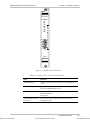
DC power supply module, PS-LRS/48 – operates on –48 VDC, and provides a
maximum total power of 120W.
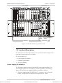
The PS modules are installed in dedicated chassis slots. The chassis has two PS
slots, enabling the installation of two PS modules, for redundancy. When both
modules are operational, they share the load; in case of failure or loss of input
power, the remaining module continues to supply the power alone. Switchover is
thus automatic and does not interrupt normal operation.
A redundant module can be installed in an operating enclosure without turning off
the enclosure power. An AC and a DC PS module can be installed simultaneously.
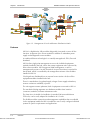
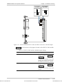
Several I/O modules installed in the chassis can supply remote (phantom) feed
voltage for the remote equipment connected to the modules installed in the
LRS-24. This voltage must be provided by an external source.
RAD offers a standalone unit, LRS-PS-FEED, that can provide the required voltage
for the remote power source. LRS-PS-FEED is explained in Appendix B of this
manual.
The phantom feed voltage is connected through the power supply interface
module and through the corresponding PS to the internal phantom feed
distribution bus of the LRS-24.
Common Logic Modules
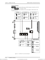
LRS-24 is managed by either of the two CM modules, CM-1 or CM-2. The main
functions of the two module types are:
•
Interfacing between a management facility and the equipment modules
installed in LRS-24. The CM-1 module only supports management by means of
a supervision terminal; the CM-2 module also supports network management
stations.
•
Distribution of an external clock signal (station clock) to the equipment
modules. The station clock interface circuits of the common logic modules
have the following user-selectable modes:
− T1 DSU interface per ANSI TR-62411 and ANSI T1.403, with 100Ω
balanced T1 line interface. This mode accepts an AMI-coded clock signal of
1544 kHz. The maximum signal attenuation is 10 dB.
− E1 DSU interface per ITU-T Rec. G.703, which accepts an
HDB3-coded clock signal of 2048 kHz. The E1 interface can be configured
to operate as a 120Ω balanced line interface, or a 75Ω unbalanced
interface. The maximum line attenuation is 10 dB.
− Square interface per TTL input.
The recovered clock signal is returned toward the equipment providing the clock
signal (remote loop condition, controlled by a user jumper).
1-12
Order from: Cutter Networks
Functional Description
Ph:727-398-5252/Fax:727-397-9610
www.bestdatasource.com