1
GLXY9.book Page 1 Thursday, February 17, 2000 3:04 PM
IntraChassis 9000
Ethernet Switch
User’s Manual
GLXY9.book Page 2 Thursday, February 17, 2000 3:04 PM
Copyright Notice
All rights reserved. No part of this manual, or any associated artwork, software, product, design or design
concept, may be copied, reproduced or stored, in whole or in part, in any form or by any means mechanical, electronic, optical, photocopying, recording or any other wise, including translation to another language or format, without the express written consent of Asanté Technologies, Inc.
Trademarks
Asanté Technologies and NetStacker are trademarks of Asanté Technologies, Inc. Ethernet is a registered
trademark of the Xerox Corporation. A ll brand names and products are trademarks or registered trademarks of their respective holders.
FCC Information
This device complies with part 15 of the FCC Rules. Operation is subject to the following two conditions:
(1) this device may not cause harmful interference and (2) this device must accept any interference received,
including interference that may cause undesired operation.
Operation of this equipment in a residential area is likely to cause interference, in which case, the user, at
his or her own risk and expense, will be required to correct the interference.
LIMITED FIVE YEAR WARRANTY
Subject to the limitations and exclusions below, Asanté warrants to the original end user purchaser that the
covered products will be free from defects in title, materials and manufacturing workmanship for a period
of five years from the date of purchase. This warranty excludes fans, power supplies, non-integrated software and accessories. Asanté warrants that the fans and power supplies will be free from defects in title,
materials and manufacturing workmanship for one year from date of purchase. Asanté warrants that nonintegrated software included with its products will be free from defects in title, materials, and workmanship
for a period of 90 days from date of purchase, and the Company will support such software for the purpose
for which it was intended for a period of 90 days from the date of purchase. This warranty expressly
excludes problems arising due to compatibility with other vendors products, or future compatibility due to
third party software or driver updates.
To take advantage of this warranty, you must contact Asanté for a return materials authorization (RMA)
number. The RMA number must be clearly written on the outside of the returned package. Product must
be sent to Asanté postage paid. In the event of a defect, Asanté will repair or replace defective product or
components with new, refurbished or equivalent product or components as deemed appropriate by Asanté.
The foregoing is your sole remedy, and Asanté's only obligation, with respect to any defect or non-conformity. Asanté makes no warranty with respect to accessories (including but not limited to cables, brackets
and fasteners) included with the covered product, nor to any discontinued product, i.e., product purchased
more than thirty days after Asanté has removed such product from its price list or discontinued shipments
of such product.
This warranty is exclusive and is limited to the original end user purchaser only. This warranty shall not
apply to secondhand products or to products that have been subjected to abuse, misuse, abnormal electrical
or environmental conditions, or any condition other than what can be considered normal use.
ASANTÉ MAKES NO OTHER WARRANTIES, EXPRESS, IMPLIED OR OTHERWISE, REGARDING THE
ASANTÉ PRODUCTS, EXCEPT TO THE EXTENT PROHIBITED BY APPLICABLE LAW, ALL WARRANTIES OR
CONDITIONS OF MERCHANTABILITY OR FITNESS FOR A PARTICULAR PURPOSE ARE HEREBY DISCLAIMED. ASANTÉ’S LIABILITY ARISING FROM OR RELATING TO THE PURCHASE, USE OR INABILITY
TO USE THE PRODUCTS IS LIMITED TO A REFUND OF THE PURCHASE PRICE PAID. IN NO EVENT WILL
ASANTÉ BE LIABLE FOR INDIRECT, SPECIAL, INCIDENTAL, OR CONSEQUENTIAL DAMAGES FOR THE
BREACH OF ANY EXPRESS OR IMPLIED WARRANTY, INCLUDING ECONOMIC LOSS, DAMAGE TO PROPERTY AND, TO THE EXTENT PERMITTED BY LAW, DAMAGES FOR PERSONAL INJURY, HOWEVER
CAUSED AND ON ANY THEORY OF LIABILITY (INCLUDING NEGLIGENCE). THESE LIMITATIONS SHALL
APPLY EVEN IF ASANTE HAS BEEN ADVISED OF THE POSSIBILITY OF SUCH DAMAGES OR IF THIS WARRANTY IS FOUND TO FAIL OF ITS ESSENTIAL PURPOSE.
Some jurisdictions do not allow the exclusion or limitation of incidental or consequential damages or limitations on how long an implied warranty lasts, so the above limitations or exclusions may not apply to you.
This warranty gives you specific legal rights, and you may have other rights, which vary from jurisdiction
to jurisdiction.
GLXY9.book Page iii Thursday, February 17, 2000 3:04 PM
Contents
1 Introduction ....................................................... 1-1
IntraCore Architecture Overview .................... 1-1
The Core Switching Engine ...................... 1-1
Infrastructure Connectivity ........................ 1-2
Network Management, Security, Performance, and
Control ...................................................... 1-2
The IntraCore Product Family ........................ 1-4
The IntraChassis 9000 ................................... 1-4
Modules ......................................................... 1-5
Network Management Module .................. 1-5
24-port 10/100 Switch Module .................. 1-6
2-port Gigabit Ethernet Switch Module ..... 1-6
Power Supply ........................................... 1-7
Features ......................................................... 1-8
Defaults and Specifications .......................... 1-10
LEDs ............................................................ 1-11
2 Installation and Set-up ..................................... 2-1
Installation Guidelines .................................... 2-1
Safety Information .................................... 2-1
Power Requirements ................................ 2-4
Environmental Requirements ................... 2-4
Cooling and Airflow ................................... 2-4
Installation Overview ...................................... 2-5
Rack Mounting/Desktop Placement ............... 2-5
Equipment Rack Installation of the Chassis 2-6
Free-Standing/Desktop Installation of the Chassis
2-8
Cable Guide Installation ........................... 2-8
Installing Modules .......................................... 2-9
Installing GBIC Interfaces ....................... 2-11
Page -iii
GLXY9.book Page iv Thursday, February 17, 2000 3:04 PM
Installing Second Power Supply ................... 2-11
Connecting Power ........................................ 2-11
Connecting to the Network ........................... 2-12
10/100BaseX Ports Cabling Procedures 2-12
1000BaseX Ports Cabling Procedures ... 2-13
Configuring for Management ........................ 2-13
BootP Configuration ................................ 2-14
Connecting To a Console ....................... 2-15
Management Options ................................... 2-16
Out-of-Band Management ...................... 2-16
In-Band Management ............................. 2-17
Management Interface ................................. 2-18
Accessing a Submenu ............................ 2-19
Exiting a Submenu .................................. 2-19
General Information Screen ......................... 2-19
Accessing General Information ............... 2-19
Configuration Menu ...................................... 2-20
Logging into the Configuration Menu ...... 2-20
Configuration Menu Options ................... 2-21
3 Basic Configuration ........................................... 3-1
Basic Configuration Overview ........................ 3-1
System Administration Configuration ............. 3-2
Current Settings ........................................ 3-2
Changing System Administration Info ....... 3-3
System IP Configuration ................................. 3-3
Current Settings ........................................ 3-4
Changing System IP Information .............. 3-4
Bootstrap Configuration .................................. 3-5
Loading Software Locally .......................... 3-7
Loading Software Remotely ...................... 3-7
Current Settings ........................................ 3-9
SNMP Configuration ..................................... 3-11
Page iv
GLXY9.book Page v Thursday, February 17, 2000 3:04 PM
Current Settings ...................................... 3-12
Changing Community Strings ................. 3-12
Enabling Authentication Traps ................ 3-13
Adding or Updating a Trap Receiver ...... 3-13
Deleting a Trap Receiver ........................ 3-13
Port Configuration ........................................ 3-14
Viewing Legends for Configuration Settings 3-16
Current Port Settings .............................. 3-17
Enabling or Disabling a Port ................... 3-17
Configuring Auto-negotiation .................. 3-18
Configuring a Port Manually ................... 3-19
Configuration of 1000BaseX ports ......... 3-20
Enabling or Disabling a Port ................... 3-20
Advanced Port Configuration ....................... 3-22
Advanced 10/100BaseTX Port Configuration 3-22
Current Settings ...................................... 3-22
Setting the Maximum Broadcast or Multicast Rate
3-23
Enabling or Disabling 802.3x Flow Control 3-24
Setting Port Default Priority .................... 3-24
Advanced 1000BaseX Port Configuration 3-26
Global Port Configuration ............................. 3-26
Unicast Forwarding Database Configuration 3-28
Current Settings ...................................... 3-30
Displaying the Forwarding Database ...... 3-30
Searching for a MAC Address ................ 3-36
Setting the MAC Address Age-Out Time 3-37
Image File Downloading Configuration ........ 3-37
Image Downloading Through TFTP ....... 3-38
Serial Downloading Configuration .......... 3-41
System Reset Configuration ........................ 3-44
Current Options ...................................... 3-44
Resetting the IntraChassis 9000 ............ 3-45
Scheduling a Reset ................................ 3-45
Page -v
GLXY9.book Page vi Thursday, February 17, 2000 3:04 PM
Viewing the System Log ............................... 3-46
Clearing the System Log ......................... 3-47
Viewing Current Operating Information ........ 3-48
User Interface Configuration ........................ 3-50
Current Settings ...................................... 3-50
Setting Console Idle Time-out Period ..... 3-51
Setting Telnet Idle Time-out Period ........ 3-51
Changing the Password .......................... 3-52
..................................................................... 3-52
4 Statistics ........................................................... 4-1
Viewing Statistics ........................................... 4-1
5 Advanced Management .................................... 5-1
Spanning Tree Protocol .................................. 5-1
Overview ................................................... 5-1
How It Works ............................................. 5-2
Enabling and Disabling STP ..................... 5-2
Configuring Spanning Tree Parameters ... 5-2
Current STP Settings ................................ 5-5
Spanning Tree Port Configuration ............ 5-5
Setting Port Priority and Path Cost ........... 5-6
SNMP and RMON Management .................... 5-7
RMON Management ................................. 5-7
Security .......................................................... 5-8
Enabling and Disabling Duplicated-IP Detection 510
Enabling and Disabling Duplicated-IP Trap 5-10
Enabling and Disabling Station Movement Trap 510
Viewing a List of Duplicated-IP Addresses 5-11
Resetting Security to Defaults ................. 5-11
VLAN Management ...................................... 5-11
Page vi
GLXY9.book Page vii Thursday, February 17, 2000 3:04 PM
VLAN Specifications for the IntraChassis 9000 512
Other VLAN Features in IntraChassis 9000 5-14
Abbreviations .......................................... 5-14
Default VLAN .......................................... 5-15
Port VLAN ID .......................................... 5-15
Port Admit Frame Type .......................... 5-16
Port Ingress Filtering .............................. 5-16
VLAN Port Membership and Untagging . 5-16
6 Web Browser Management .............................. 6-1
Accessing with a Web Browser ...................... 6-1
Management Buttons ..................................... 6-2
Front Panel Button ......................................... 6-3
Genl Info (General Information) Button .......... 6-5
Statistics Button ............................................. 6-6
Port Config (Port Configuration) Button ......... 6-9
Span Tree (Spanning Tree) Button .............. 6-10
SNMP Button ............................................... 6-11
Addr (Address) Table Button ....................... 6-12
VLAN Button ................................................ 6-13
Duplicate IP Button ...................................... 6-17
Contacting Technical Support .................. A-1
MIB Object Definitions for Counters ......... B-1
App. A Technical Support .................................. A-1
App. B MIB Statistics .......................................... B-1
Page -vii
GLXY9.book Page viii Thursday, February 17, 2000 3:04 PM
Page viii
GLXY9.book Page 1 Thursday, February 17, 2000 3:04 PM
1
Introduction
This chapter introduces the IntraChassis 9000 architecture, then gives a
description of the chassis and the various modules that can be installed in it.
There are also tables of the key features, default settings, and specifications of
the IntraChassis 9000, and explanations of the different LED indicators used by
the various modules.
IntraCore Architecture Overview
Asanté has developed the IntraCore™ Architecture to meet the needs of multiservice networks that support all applications and data types. The architecture is
standards-based and provides
❑
multi-vendor inter operability
❑
a migration path from current systems
❑
investment protection
With the IntraCore Architecture, Asanté has found innovative ways of
embracing industry standards and technology advances to create products
capable of meeting real world requirements for converged, multi-service
networks.
The overall design incorporates a family of tightly integrated ASICs, designed as
system building blocks. These building blocks enable the rapid development of
advanced networking systems that are timed to meet market requirements. The
architecture ensures consistent high performance as systems scale their capacity
and feature capability. This approach extends the useful life of the system and
protects customer investments.
The Core Switching Engine
The Core Switching Engine is the centerpiece for all IntraCore products. Based
on advanced silicon ASICs, the Core Switching Engine is a high performance,
non-blocking, multi-gigabit switching fabric with scalable bandwidth capacity.
The Core Switching Engine is data format independent and can support either
frame or cell based interfaces. This capability is becoming increasingly
Page 1-1
GLXY9.book Page 2 Thursday, February 17, 2000 3:04 PM
Introduction
important as enterprise (primarily frame-based) and service provider (primarily
cell-based) networks move closer together.
Infrastructure Connectivity
The second key element of the architecture is Infrastructure Connectivity.
IntraCore specifies standards based, high performance, cost effective
technologies for connectivity among devices in the network.
In the LAN –
At the network edge, Layer 2 switched 10/100/1000 Ethernet meets the
requirements for high-speed connectivity of desktop computers and scalable,
cost effective data transmission for trunks to the network core.
In the network core, Layer 2/3+-switched 10/100/1000 Ethernet meets the
requirements for high speed, scalable, cost effective data transmission and
support for all multi-service data types. High performance servers can be
centrally located for added physical security.
Throughout the LAN, advanced queuing techniques combined with multiple
priority levels and support for industry standard 802.1Q and 802.1p enable
Quality of Service within the network.
In the MAN/WAN –
Long haul Gigabit Ethernet, ATM, and Packet over SONET meet the
requirements for all of the following:
❑
scalable, cost effective data transmission
❑
support for all multi-service data types
❑
service provider inter operability
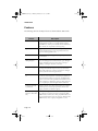
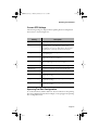
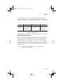
Network Management, Security, Performance, and
Control
IntraCore includes a rich suite of features required for the effective
management, security, performance and control of the network. The following
table illustrates the features and standards supported as part of this section of
the overall architecture.
Page 1-2
GLXY9.book Page 3 Thursday, February 17, 2000 3:04 PM
IntraCore Architecture Overview
Management
Feature
Security
Performance
Control
Web Browser Management
Supported
SNMP, RMON
Supported
Supported
Supported
Standard MIsS
Supported
Supported
Supported
Supported
Supported
Supported
Supported
Supported
Supported
IGMP V1, V2 Snooping
Supported
Supported
RSVP Snooping
Supported
Supported
GARP Multicast Registration
Supported
Supported
802.1P Priority
802.1Q VLAN Tagging
Supported
802.1D – Spanning Tree
Supported
Duplicate IP addr. detection
Supported
Supported
Station movement notification
Supported
Supported
IP to MAC address binding
Supported
Supported
Supported
Controlled management
access
GVRP (Group VLAN Registration Protocol)
Supported
Supported
Supported
Advanced Port Configuration: Broadcast & Multicast
rate limit & port priority
Supported
Supported
Supported
Policy management: IntServ
(RSVP), DiffServ, COPS
Supported
Supported
Supported
Supported
Directory services: DNS,
DHCP, LDAP
Supported
Supported
Supported
Supported
Table 1-1
Summary of IntraCore’s supported features
Page 1-3
GLXY9.book Page 4 Thursday, February 17, 2000 3:04 PM
Introduction
The IntraCore Product Family
The Asanté IntraCore architecture is the basis for a family of switching system
products in fixed, stackable and chassis form factors that allow customers to
integrate telephony, video and data applications. Initially two systems will be
offered that provide high performance, high port count Layer 2 switching.
Additional configurations will be introduced to offer advanced Layer 3 and
above routing, traffic classification, advanced QoS, higher bandwidth and port
capacity. All systems will be consistent in their operation and management
allowing customers to seamlessly deploy any model in their network.
Edge Switches
Providing the first point of connectivity to the network are the Edge Switches.
These connect to an Enterprise switch in the network core and provide
aggregation of traffic from desktop computers over high capacity trunks. The
initial product introduced in the Edge Switch category is the IntraStack 8000.
The IntraStack 8000 is a stackable, high performance solution for enterprise
edge applications. Each stack supports up to 192 10/100Mbps switched
Ethernet connections for cost-effective high-density connectivity in wiring
closets. The system can operate as a stand-alone network or be used in
combination with IntraChassis 9000 in the backbone.
Enterprise Switches
In the network core, Enterprise Switches are deployed to aggregate traffic from
wiring closets and provide high-speed connectivity to network servers. Typically
these switches are modular in form factor, and can be easily upgraded or
reconfigured. This flexibility provides for customized configurations to meet a
wide variety of requirements. The initial product introduced in this category is
the IntraChassis 9000.
The IntraChassis 9000
The IntraChassis 9000 is a chassis based modular Gigabit Ethernet enterprise
switch designed for either high density wiring closets or as the core of the
network backbone. The system can support up to 192 10/100Mbps switched
Ethernet or 16 switched Gigabit Ethernet connections. System modules offer
choice in media and connector types to best suit existing wiring infrastructure
systems.
Page 1-4
GLXY9.book Page 5 Thursday, February 17, 2000 3:04 PM
Modules
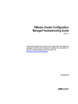
Figure 1-1 IntraChassis 9000 Front Panels
Modules
The following modules can be installed in the IntraChassis 9000 chassis.
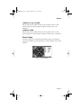
Network Management Module
This module is included with the IntraChassis 9000 chassis, and provides
management for it and all other modules you install. It occupies one slot, and
has a single DB-9 port for the console. The module supports Telnet and Web
Page 1-5
GLXY9.book Page 6 Thursday, February 17, 2000 3:04 PM
Introduction
Browser management via industry standard SNMP with support for MIB II,
RMON (four groups), Bridge MIB, and Asanté private MIBs.
Figure 1-2 Management Module
24-port 10/100 Switch Module
This module provides 24 ports supporting switched 100BaseTX or 10BaseT
per port. Each module occupies a single slot and has either 24 RJ-45
connectors, or 2 RJ-21 connectors.
Figure 1-3 24-port 10/100 Switch Module
2-port Gigabit Ethernet Switch Module
This module provides slots for two switched Gigabit Ethernet ports. Each
module occupies a single slot and has 2 GBIC interfaces, which accept Asanté
or third party GBIC interfaces. The following subsections describe the possible
GBIC interfaces.
Figure 1-4 2-port Gigabit Ethernet Switch Module
1000Base SX GBIC
This module provides a GBIC interface with SC-type fiber connectors. The
interface supports 62.5 and 50 micron multimode fiber media. The 62.5
micron multimode fiber can be up to 260 meters long, and the 50 micron
multimode fiber can be up to 525 meters long.
Page 1-6
GLXY9.book Page 7 Thursday, February 17, 2000 3:04 PM
Modules
1000BaseLX Long Haul GBIC
This module provides a GBIC interface for SC-type fiber connectors. The
interface supports 10 micron single mode fiber for distances up to 100
kilometers.
1000BaseLX GBIC
This module provides a GBIC interface for SC-type fiber connectors. The
interface supports 10 micron single mode fiber for distances up to 3 kilometers.
Power Supply
One Power Supply is provided with the IntraChassis 9000. A second Power
Supply can be added to provide additional power and redundancy for the other
modules.
Figure 1-5 Power Supply
Page 1-7
GLXY9.book Page 8 Thursday, February 17, 2000 3:04 PM
Introduction
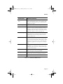
Features
The following table lists the major features of the IntraChassis 9000 switch.
Feature
Description
Media Flexibility
Expansion module options include 24-port 10/100 Base-TX
switched Ethernet modules, 2-port Gigabit Ethernet modules
with GBIC slots, and 24-port 10/100 Base-TX switched Ethernet
RJ-21 modules for compatibility with existing wiring.
High Density
Supports up to 192 10/100 switched Ethernet ports or up to 16
switched Gigabit Ethernet ports in a single chassis. This saves
space in crowded equipment rooms.
ASIC-Based Architecture
ASIC-based packet processing provides wire speed performance
on all interfaces.
High Performance
16Gbps Backplane
The system supports current requirements for multi-service voice,
video, and data applications with bandwidth to spare. The highcapacity backplane is designed so that it may be scaled up to
128Gbps, extending the useful life of the chassis.
Multiple Priority Queues
The “application aware” system ensures that mission critical applications get the bandwidth and priority they need, even under
heavy traffic conditions. Low latency requirements are managed
by the system when network congestion occurs.
Chassis Based Form Factor
The nine slot modular chassis allows configuration flexibility and
cost effective network expansion. A wide variety of switched 10/
100/1000 Ethernet interfaces are supported, with flexible media
options to meet all network requirements. The IntraChassis 9000
can be configured as a high-density switch for campus wiring closets, or a high-capacity switch for Gigabit Ethernet backbones.
Configuration Flexibility and Growth
Expansion modules can be mixed and matched in any configuration and quantity to meet design requirements. You can add
capacity only when your business requires it.
GBIC Modules for Gigabit Ethernet Media Flexibility
The two GBIC Gigabit Ethernet modules can be configured with
any combination of 1000SX, 1000LX or 1000LX (Long Haul)
GBIC interfaces. Either Asanté or third party GBIC interfaces can
be used, and the interfaces can be “hot swapped.” This means that
GBIC interfaces can be re-deployed if equipment is retired.
Page 1-8
GLXY9.book Page 9 Thursday, February 17, 2000 3:04 PM
Features
Feature (Cont.)
Definition (Continued)
Reliability and Redundancy
For maximum uptime and minimum network disruption, the
interface and management modules are hot-swappable. Configuration options include support for up to two load-sharing, hotswappable power supplies.
Installation Options
The system can be rack-mounted to save space.
Security
Node summary tracks MAC and IP addresses per device, for multiple devices on each port. The New Node Detection feature provides per-port security, allowing the network manager to specify
which MAC is authorized on each port. Only the device with that
MAC address is allowed to connect to that specific port.
Web Based Management
Built-in Web-based interface is provided for chassis management,
module management, port-level control, and monitoring. The
IntraChassis 9000 can also be managed via Telnet, Console, or
third party SNMP console.
VLANs
Supports up to 64 port-based VLANs (IEEE 802.1Q compliant)
for security, logical network design, and the control of broadcast
traffic. The 802.1Q standard specifies VLAN tagging for trunking
VLANs from switch to switch, or switch to router. Compatible
with all 802.1Q equipment for easy integration into existing networks.
Multicast Control
The IntraChassis 9000 supports standards based IGMP snooping
and GMRP for control of multicast traffic generated by bandwidth-hungry applications like video, ensuring maximum application and network performance.
RMON
The administrator can use a RMON probe for in-depth traffic
analysis, with support for four groups of RMON.
Spanning Tree Protocol
Spanning Tree Protocol (STP) detects and eliminates data loops to
prevent broadcast storms from overwhelming your network.
Y2K compliance
All IntraChassis 9000 modules are Y2K compliant.
Table 1-2
IntraChassis 9000 Features
Page 1-9
GLXY9.book Page 10 Thursday, February 17, 2000 3:04 PM
Introduction
Defaults and Specifications
The IntraChassis 9000 is shipped with the following factory default settings
and specifications:
Configuration
Default Setting
Backplane Speed
32Gbps.
Switching Method
Store-and-forward
Forwarding Rates:
(64 byte packets)
Switched 10Mbps = 14,880 pps
Switched 100Mbps = 148,810 pps
Switched 1000Mbps = 1,488,100 pps
Buffer Size
4MB
MAC Address Table
8K
Full-Duplex
Standards based Auto-negotiation enabled
VLAN
64 port based VLANs, GVRP support, 802.1Q VLAN Tagging
Spanning Tree Protocol
802.1D, enabled
Flood Rate Limiting
Broadcast traffic
Priority
802.1Q, 8 levels mapped to 4 Queues
RMON
Groups 1-3, 9
SNMP
MIB-II, Bridge MIB, RMON MIB, Asanté private MIBs
Console Baud Rate
9600
Password
Asanté
Power Requirements
90 - 224 V, 50 - 60 Hz
Environmental Operating Range
Temperature: 0° - 45° C (Storage: -40° - 85° C)
Relative Humidity: 5% - 95% non-condensing
Table 1-3
Page 1-10
Defaults and Specifications
GLXY9.book Page 11 Thursday, February 17, 2000 3:04 PM
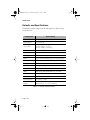
LEDs
LEDs
The following indicator lights are used on the various modules of the
IntraChassis 9000.
Color and Meaning
LED
Management Module
Power
Green - Power is on when lit
Slot Control Center
Green - upper row - For future functionality
Green - lower row - Module is installed in this slot.
Gigabit Switch (GBIC)
Power
Green - Power is on when lit
Link
Green - connection and link has been made.
24-port 10/100 Switch
Link/Speed
Green - Link at 100Mbps
Duplex/Activity
Green -Full Duplex
Amber - Link at 10Mbps
Amber - Half Duplex
Blinking - Active
Power Module
Power
Green - Power is available to IntraChassis 9000
P-Fail
Amber - Power is not available to module
Fail
Amber - Power module is not delivering power
Table 1-4
LEDs and their meanings
Page 1-11
GLXY9.book Page 12 Thursday, February 17, 2000 3:04 PM
Introduction
Page 1-12
GLXY9.book Page 1 Thursday, February 17, 2000 3:04 PM
2
Installation and Set-up
This chapter explains how to install, connect, and configure the IntraChassis
9000 chassis and modules to work with your network. It also explains how to
set up your IntraChassis 9000 for management, either from a console, via
telnet, via SNMP, or by using a Web browser.
Installation Guidelines
The following guidelines will help you prepare to install your IntraChassis 9000
in such a way that it has the proper power supply and environment.
Safety Information
The following sections provide guidelines and procedures to help you install
and use the IntraChassis 9000 safely.
Safety First
Use the following guidelines to ensure your safety and protect the equipment.
This list is not inclusive of all potentially hazardous situations that you may be
exposed to as you install the switch, so be alert.
❑
Never try to lift an IntraChassis 9000 chassis by yourself; two people
are required to lift these switches.
❑
Always unplug all power cords before installing or removing a chassis
or removing the chassis front panel.
❑
Keep the chassis area clear and free of dust during and after installation.
❑
Keep tools and chassis components off the floor and away from foot
traffic.
❑
Avoid wearing jewelry (including rings and chains) or other items
that could get caught in the chassis. Avoid wearing any loose clothing
or securely fasten items such as ties, scarves, or sleeves.
❑
Install the system in compliance with the following local and national
electrical codes:
Page 2-1
GLXY9.book Page 2 Thursday, February 17, 2000 3:04 PM
Installation and Set-up
❑ United States—National Fire Protection Association
(NFPA 70); United States National Electrical Code
❑ Canada—Canadian Electrical Code, Part I, CSA C22.1
❑ Other countries—International Electrotechnical Commission (IEC) 364, Part 1 through Part 7
▲
Important: Take the following precautions when installing
the IntraChassis 9000:
Only trained and qualified personnel should be allowed to
install or replace this equipment.
This equipment is to be installed and maintained by service
personnel only as defined by AS/NZS 3260 Clause 1.2.14.3
Service Personnel.
Before working on equipment that is connected to power
lines, remove jewelry (including rings, necklaces, and
watches). Metal objects will heat up when connected to
power and ground and can cause serious burns or weld the
metal object to the terminals.
Unplug the power cord before you work on a system that
does not have an on/off switch.
Before installing the IntraChassis 9000, unplug the power
cord.
Do not work on the system or connect or disconnect cables
during periods of lightning activity.
Do not touch the power supply when the power cord is
connected. Line voltages are present within the power supply when the power cord is connected.
Read the installation instructions before you connect the
system to its power source.
This unit might have more than one power cord. To reduce
the risk of electric shock, disconnect the two power supply
cords before servicing the unit.
Do not stack the chassis on any other equipment. If the
chassis falls, it can cause severe bodily injury and equipment
damage.
Page 2-2
GLXY9.book Page 3 Thursday, February 17, 2000 3:04 PM
Installation Guidelines
Lifting the Chassis Safely
The IntraChassis 9000 is not intended to be moved frequently. Before you
install the switch, ensure that your site is properly prepared so that you can
avoid moving the chassis later to accommodate power sources and network
connections.
Two people are required to lift the IntraChassis 9000. Whenever you lift the
chassis or any heavy object, follow these guidelines:
❑
Never attempt to lift a chassis by yourself. The size and weight of a
chassis requires two people to safely lift and move it without causing
injury or damaging the equipment.
❑
Ensure that your footing is solid, and balance the weight of the chassis between your feet.
❑
Lift the IntraChassis 9000 slowly; never move suddenly or twist your
body as you lift.
❑
Keep your back straight and lift with your legs, not your back. If you
must bend down to lift the chassis, bend at the knees, not at the
waist, to reduce the strain on your lower back muscles.
❑
Leave all switch and power modules in place once they are properly
installed.
❑
Always disconnect all external cables before lifting or moving the
chassis.
Safety With Electricity
The secondary power supply is designed to be removed and replaced while the
system is operating without presenting an electrical hazard or damage to the
system. Before removing a redundant power supply, ensure that the other power
supply is turned on.
Follow these basic guidelines when working with any electrical equipment:
❑
Before beginning any procedures requiring access to the chassis interior, locate the emergency power-off switch for the room in which
you are working.
❑
Disconnect all power and external cables before installing or removing a chassis.
❑
Do not work alone when potentially hazardous conditions exist.
❑
Never assume that power has been disconnected from a circuit;
Page 2-3
GLXY9.book Page 4 Thursday, February 17, 2000 3:04 PM
Installation and Set-up
always check.
❑
Do not perform any action that creates a potential hazard to people
or makes the equipment unsafe.
❑
Carefully examine your work area for possible hazards such as moist
floors, ungrounded power extension cables, and missing safety
grounds.
❑
Never install telephone jacks in wet locations unless the jack is specifically designed for wet locations.
❑
Never touch uninsulated telephone wires or terminals unless the telephone line has been disconnected at the network interface.
❑
Never touch uninsulated telephone wires or terminals unless the telephone line has been disconnected at the network interface.
Power Requirements
The source electrical outlet should be installed near the IntraChassis 9000 and
easily accessible. It must also be properly grounded.
Make sure the power source adheres to the following guidelines:
❑
Voltage range: 100 to 240 VAC
❑
Frequency range: 60/50 Hz
❑
Maximum current: 10 A per power supply at 110 volts
Environmental Requirements
The IntraChassis 9000 must be installed in a clean, dry, dust-free area with
adequate air circulation to maintain the following environmental limits:
❑
Temperature: 0° to 40° C (32° to 104° F)104°
❑
Relative Humidity: 5% to 85% non-condensing
Avoid direct sunlight, heat sources, or areas with high levels of electromagnetic
interference.
Cooling and Airflow
Do not restrict air flow by covering or obstructing air vents on the sides of the
chassis.
Page 2-4
GLXY9.book Page 5 Thursday, February 17, 2000 3:04 PM
Installation Overview
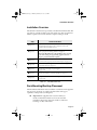
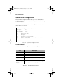
Installation Overview
The table below describes the steps needed to install the IntraChassis 9000. The
steps that are optional are labeled “optional” and the steps that are required are
labeled “required.” The sections that follow explain each step in detail.
Step
Action to Be Taken
1(Required)
Open the box and check the contents.
See the Package Contents sheet for a complete list of the items
included with your IntraChassis 9000.
2(Required)
Install the IntraChassis 9000 chassis in an equipment rack or wall
rack, or prepare it for desktop placement. See page 2-5.
Important! When fully loaded, the IntraChassis 9000 can weigh
over 100 lbs (45 Kg). Use proper lifting equipment and techniques to prevent back and other injuries.
3(Required)
Install the modules you have purchased for your IntraChassis 9000
and ensure each is properly seated and locked in place. See page 2-9.
4(Optional)
Install a second power supply module and make sure it is properly
seated in the chassis. See page 2-11.
5(Required)
Connect the power supply or power supplies.
See page 2-11.
6(Required)
Connect the modules to your network cables. See page 2-12.
7(Required)
Configure the IntraChassis 9000 for management capabilities.
See page 2-13.
Table 2-1
Installation Overview
Rack Mounting/Desktop Placement
The IntraChassis 9000 chassis can be installed in a standard 19-inch equipment
rack. It can also be placed on a stable horizontal surface with support
capabilities of 150 pounds (68.2 kilograms).
▲
Important: The equipment rack or desk on which you
install your IntraChassis 9000 must be secure and stable.
Equipment racks must be fastened to the floor; desks must
be resting on a flat, stable surface.
Page 2-5
GLXY9.book Page 6 Thursday, February 17, 2000 3:04 PM
Installation and Set-up
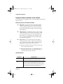
Equipment Rack Installation of the Chassis
To install the unit in an equipment rack, use the following procedure. Refer to
Figure 2-1 below.
Safety Precautions for Rack Installation
▲
Important! Disconnect all cables from the IntraChassis
9000 before continuing. Also, do not install the modules
you have purchased until the chassis has been installed in
the rack. This will reduce the weight of the chassis during
rack installation.
▲
Important! Before installing the chassis in a rack, read the
“Safety Information” section earlier in this chapter to familiarize yourself with the proper site and environmental conditions. Failure to read and follow these guidelines could
lead to an unsuccessful installation and possible damage to
the system and components.
▲
Important! To prevent bodily injury when mounting or
servicing this unit in a rack, you must take special precautions to ensure that the system remains stable. The following guidelines are provided to ensure your safety:
❑ This unit should be mounted at the bottom of the rack
if it is the only unit in the rack.
❑ When mounting this unit in a partially filled rack, load
the rack from the bottom to the top with the heaviest
component at the bottom of the rack.
Rack Guidelines
Guideline
Specification
Size
Width; 17.75 inches (45.09 cm).
Depth: 19.25 inches (48.9 cm) to 32 inches (81.3 cm).
Stability
Rack must be bolted to the floor. Mount heavier units at the bottom
of the rack, and mount the IntraChassis 9000 at the bottom of the
rack if it is the only unit mounted; this will ensure that the rack does
not become top-heavy. If the rack has stabilizing devices, make sure
they are installed before mounting the IntraChassis 9000.
Page 2-6
GLXY9.book Page 7 Thursday, February 17, 2000 3:04 PM
Rack Mounting/Desktop Placement
Guideline
Specification
Ventilation
Ensure that the rack is installed in a room where the temperature
remains below 40° C (104° F). Ensure also that there are no
obstructions, such as other equipment or cables, blocking airflow to
or from the IntraChassis 9000 vents.
Clearance
In addition to providing clearance for ventilation, ensure that there is
adequate clearance for servicing the modules of the IntraChassis 9000
from the front.
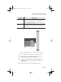
Figure 2-1 Mounting rack bracket on the IntraChassis 9000 chassis
1
2
Place the IntraChassis 9000 chassis on a flat, stable surface.
3
Insert five screws (supplied) into the holes and tighten with
a Phillips screwdriver. Do not use less than six screws for
this mounting.
4
Repeat the two previous steps for the unit’s other side.
Locate a rack-mounting bracket (supplied) and place it over
the mounting holes on one side of the unit.
Page 2-7
GLXY9.book Page 8 Thursday, February 17, 2000 3:04 PM
Installation and Set-up
5
Place the unit in the equipment rack.
▲ Important! When fully loaded, the IntraChassis 9000
can weigh over 100 lbs. Use proper lifting equipment
and techniques, as described in “Lifting the Chassis
Safely” earlier in this chapter, to prevent back and other
injuries.
6
Secure the unit by screwing its mounting brackets to the
equipment rack. Use a minimum of six {right?} screws for
this purpose.
▲ Important! Make sure the unit is supported until all
the mounting screws for each bracket are secured to the
equipment rack. Failure to do so could cause the unit to
fall, resulting in personal injury or damage to the unit,
or both.
7
Proceed to the “Cable Guide Installation” section.
Free-Standing/Desktop Installation of the Chassis
The IntraChassis 9000 chassis has four rubber feet on the bottom of the chassis
that allow for free-standing installation of the unit.
For free-standing/desktop placement:
1
Attach the four rubber pads (supplied) to the bottom of
each corner of the IntraChassis 9000 chassis.
2
Place the unit on a flat surface with a minimum area of
17.1” x 13.5” (434.3 mm x 342.9 mm) and support capacity of 150 lbs (68.2 kg).
3
Make sure there is enough ventilation space between the
IntraChassis 9000 and surrounding objects.
4
Proceed to “Cable Guide Installation” below.
Cable Guide Installation
Before installing any of the modules in your IntraChassis 9000, place the cable
guide hook units on each side of the front panel and attach them with the
screws provided. Make sure you install the guides in such a way that the hooks
open upward.
Page 2-8
GLXY9.book Page 9 Thursday, February 17, 2000 3:04 PM
Installing Modules
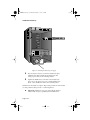
Installing Modules
Up to eight IntraChassis modules can be installed in the IntraChassis 9000
chassis, in addition to the Management Engine module, which is pre-installed
in the factory.
Before installing any modules, make sure the cable guides have been installed, as
explained in the previous section of this chapter.
To install any combination of 2-port Gigabit Ethernet Switch (GBIC) modules
and 24-port 10/100 Switch modules, use the following procedure.
▲
Important: Make sure the IntraChassis 9000 chassis is
properly installed in an equipment rack or resting on a flat,
stable surface capable of supporting 150 pounds (68.2kg).
Also make sure the power cord for the power module is disconnected for initial installation.
1
Pull the small ejector lever on each end of the module’s face
plate out, away from the face plate.
2
Align the bottom of the module with the rails on the inside
of the chassis slot where you want to install the module, as
shown in Figure 2-2.
3
Slide the module into the slot until it stops, then push the
module in gently until it seats with the connector.
Page 2-9
GLXY9.book Page 10 Thursday, February 17, 2000 3:04 PM
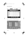
Installation and Set-up
Advanced Systems
Galaxy 9000 GigaSwitch
IntraChassis 9000
Management Engine
Mode
Set
Power
1 2 3 4 5 6 7 8
Slot Control Center
2
4
6
8
10 12 14 16 18 20 22 24
1
3
5
7
9 11 13 15 17 19 21 23
2
4
6
8
10
12
14
16
18
20
22
24
1
3
5
7
9
11
13
15
17
19
21
23
Link/Speed
IntraChassis 9000
24-port 10/100 Switch Blade
Duplex/Act
Link/Speed
Duplex/Act
Power
2
4
6
8
10 12 14 16 18 20 22 24
1
3
5
7
9 11 13 15 17 19 21 23
2
4
6
8
10 12 14 16 18 20 22 24
2
4
6
8
10
12
14
16
18
20
22
24
1
3
5
7
9
11
13
15
17
19
21
23
4
6
8
10
12
14
16
18
20
22
24
2
3
5
7
9
11
13
15
17
19
21
23
1
Link/Speed
IntraChassis 9000
24-port 10/100 Switch Blade
Duplex/Act
Link/Speed
Duplex/Act
Power
Link/Speed
Duplex/Act
IntraChassis 9000
24-port 10/100 Switch Blade
Power
Link/Speed
Duplex/Act
1
3
5
7
9 11 13 15 17 19 21 23
Power
!
P-Fail
Fail
CM
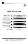
Figure 2-2 Installing module and power supply
4
Press both ejector levers in, toward the module’s face plate,
simultaneously. This will lock the module in place and
insure proper contact of all connecting surfaces.
5
Tighten the thumbscrews at the ends of the module’s face
plate, next to the ejector levers. Use a straight-bladed screwdriver, so the thumbscrews cannot be loosened by hand.
Installation of the module is complete. Repeat this procedure for each module
you have purchased, then proceed to “Connecting Power”.
▲
Important: Modules are not to be removed from the IntraChassis 9000 except by a qualified System Administrator.
Page 2-10
GLXY9.book Page 11 Thursday, February 17, 2000 3:04 PM
Installing Second Power Supply
Installing GBIC Interfaces
If you have installed modules for GBIC interfaces, install each interface itself by
sliding it into the port, until the locking tabs on either side of the GBIC
interface unit click into the locked position. You can then connect the SC-type
fiber media.
To remove a GBIC interface, squeeze the locking tabs against the sides of the
unit until they release it, then slide the interface out of the port.
Installing Second Power Supply
To install a power supply module in your IntraChassis 9000, first loosen and
undo the thumbscrew holding the cover plate, then remove the plate and slide
the second power supply into the chassis from the front, as shown in Figure 2-2.
Tighten the thumbscrew to hold the power supply firmly in place.
Connecting Power
To connect power to the IntraChassis 9000, use the following procedure.
▲
Important: Carefully review the power requirements on
page 2-4 before connecting power to the IntraChassis 9000.
1
If you have purchased a second power supply, insert it in the
bay provided at the bottom of the IntraChassis 9000 chassis, as shown in Figure 2-2.
2
Plug one end of the supplied power cord into the power
connector on the back of the unit.
3
Plug the other end into a grounded AC outlet.
▲ Important: If the power does not come on, refer to
Appendix A, “Troubleshooting.”
The IntraChassis 9000 is ready for connection to the network.
Page 2-11
GLXY9.book Page 12 Thursday, February 17, 2000 3:04 PM
Installation and Set-up
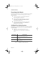
Connecting to the Network
The IntraChassis 9000 unit may be connected to an Ethernet network, with the
unit powered either on or off. Use the following procedure to make your
network connections.
1
Connect network devices to the IntraChassis 9000, following the cable guidelines outlined below.
2
Route the cables through the cable supports at the ends of
each module, to keep cables from the different modules
from interfering with each other.
3
After the unit is connected to the network, it can be configured for management capabilities. See “Configuring for
Management” later in this chapter.
10/100BaseX Ports Cabling Procedures
The 24 fixed ports on each 10/100 module allow for the connection of 10BaseT or 100Base-TX network devices. The ports are compatible with IEEE 802.3
and 802.3u standards.
▲
Important: The IntraChassis 9000 must be located
within 100 meters of its attached 10Base-T or 100Base-TX
devices.
Connecting To
Cable Required
Network Station
Category 5 UTP (Unshielded Twisted-Pair) straight-through cable
(100 meters maximum) with RJ-45 connectors.
Repeater/Hub
Category 5, UTP cross-over cable (100 meters maximum) with RJ45 connectors.
Repeater/Hub’s Uplink
port
Category 5, UTP straight-through cable (100 meters maximum)
with RJ-45 connectors.
Table 2-2
Page 2-12
10/100BaseTX cabling requirements
GLXY9.book Page 13 Thursday, February 17, 2000 3:04 PM
Configuring for Management
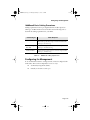
1000BaseX Ports Cabling Procedures
Cabling requirements for the 2-port Gigabit Ethernet modules depend on
which type of GBIC interface has been installed. Use the following chart to
determine the cabling requirements for your GBIC.
Connecting To
Cable Required
1000BaseSX GBIC
Cables with SC-type fiber connectors: 62.5 micron multimode
fiber media up to 260 meters long, or 50 micron multimode fiber
media up to 525 meters long.
1000BaseLX Long
Haul GBIC
Cables with SC-type fiber connectors: 10 micron single mode fiber
media up to 100 kilometers long.
1000BaseLX GBIC
Cables with SC-type fiber connectors: 10 micron single mode fiber
media up to 3 kilometers long.
Table 2-3
1000BaseX cabling requirements
Configuring for Management
To use the IntraChassis 9000 as a managed switch, it must be configured with
an IP address. This can be accomplished in one of two ways:
❑
automatically using BootP (default)
❑
manually via the unit’s Console port
Page 2-13
GLXY9.book Page 14 Thursday, February 17, 2000 3:04 PM
Installation and Set-up
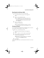
BootP Configuration
The IntraChassis 9000 is shipped with BootP support. BootP allows the
IntraChassis 9000 to be automatically configured with an IP address when it is
connected to the network and is powered on, if your network contains a BootP
server configured with available, valid IP addresses. Use the following procedure
to set up BootP.
▲
Important: BootP configuration only works if the
IntraChassis 9000 does not have an IP address assigned to
it.
1
Make sure your network has a BootP server configured with
a valid IP address entry for the IntraChassis 9000.
2
When the IntraChassis 9000 is connected to the network
and is powered on, it automatically transmits a BootP
request across the network (up to 10 times) until it receives
a valid IP address from the BootP server.
3
After an IP address is received, the IntraChassis 9000 can be
managed via in-band access. See Chapter 3, “Basic Configuration” for more information.
To verify that a valid IP address was received, try to ‘ping’ the IntraChassis
9000; if you can access the IntraChassis 9000, it is properly configured with an
IP address.
See “Bootstrap Configuration” in Chapter 3 for more information on using
BootP.
Page 2-14
GLXY9.book Page 15 Thursday, February 17, 2000 3:04 PM
Configuring for Management
Connecting To a Console
Use the following procedure to make the cable connection from a terminal to
the console port on the Management Engine of the IntraChassis 9000.
1
Using a straight-through RS-232 cable with a 9-pin male
D-subminiature plug at one end, connect a terminal or
workstation (PC or Macintosh) running a terminal emulator to the Console port on the front of the IntraChassis
9000.
2
Make sure both units are powered on.
If using a PC with a terminal emulator, make sure it is configured with the following terminal settings:
❑ Baud: 9600
❑ Data Bits: 8
❑ Parity: None
❑ Stop Bits: 1
❑ Flow Control: None
3
Once connected, the Local Management Main Menu
appears on the terminal screen.
For further information on setting an IP address for configuration of a terminal,
or a PC running a VT100 terminal or emulator (such as HyperTerminal,
ProComm, or ZTerm), see “System IP Configuration” in Chapter 3.
Page 2-15
GLXY9.book Page 16 Thursday, February 17, 2000 3:04 PM
Installation and Set-up
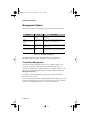
Management Options
The IntraChassis 9000 can be managed using any of the following methods:
Method
Type
Description
Console
Out-of-band man- Local connection to the IntraChassis 9000 via the
agement
Console port
Telnet
(four sessions maximum)
In-band management
Remote connection over the network to the
IntraChassis 9000 via Telnet session
HTTP Server
In-band management
Remote connection to the IntraChassis 9000 via
a Web browser
SNMP-Based Network In-band manageManagement Software ment
Remote connection to the IntraChassis 9000 via
any SNMP-based network management application
Table 2-4
Management Methods
The remaining sections of this chapter describe how to connect to the
IntraChassis 9000 using either out-of-band or in-band management.
Out-of-Band Management
Out-of-band network management allows you to configure, manage, and
monitor the IntraChassis 9000 and all of the installed modules. You can
perform these functions by attaching a terminal (or a terminal emulator) to the
Console port on the management engine and using the menu-driven Local
Management Interface.
Out-of-band network management is guaranteed even when the in-band
Ethernet network is down.
To access the IntraChassis 9000 Local Management Interface using out-of-band
management, first follow the procedure in “Connecting To a Console” and then
go on to the “Management Interface” section, later in this chapter.
Page 2-16
GLXY9.book Page 17 Thursday, February 17, 2000 3:04 PM
Management Options
In-Band Management
In-band network management allows you to manage, control, and monitor the
IntraChassis 9000 over the Ethernet network.
You can perform these functions by accessing the IntraChassis 9000 via any of
the following methods:
❑
By connecting with a Telnet program and using the Local Management Interface.
❑
By connecting with any World Wide Web browser, and using the
Web Management Interface.
❑
By connecting with any SNMP-based network management application and using its interface.
To manage the IntraChassis 9000 via in-band management, use the following
procedure.
1
Make sure the network to which the IntraChassis 9000 is
connected is functioning.
2
Make sure the IntraChassis 9000 is configured with valid IP
information.
See “Configuring for Management” earlier in this chapter.
3
Connect to the IntraChassis 9000 via Telnet, with a Web
browser, or with any SNMP-based network management
application.
Telnet
Use a network connection to any PC and enter the telnet command to
access the IntraChassis 9000. The Main Menu of the Management Interface
will appear. Go on to the “Management Interface” section below.
◆
Note: Almost all management screens using a Telnet connection are identical to those of the out-of-band Console
Interface. On the Main Menu, however, there will be a q
option for closing the connection to the IntraChassis 9000.
Web Browser
Refer to Chapter 6, “Web Browser Management”, for information on managing
the IntraChassis 9000 with a Web browser.
Page 2-17
GLXY9.book Page 18 Thursday, February 17, 2000 3:04 PM
Installation and Set-up
SNMP-Based Management
Refer to Chapter 5, “Advanced Management” and your SNMP Software
Manual for information on managing the IntraChassis 9000 with SNMP-based
management software.
The Asanté private MIB for the IntraChassis 9000 is available from the Asanté
ftp site, ftp.asante.com, or you can copy it from the Installation CD-ROM.
Access to Remote Network Monitoring (RMON) features is available only by
using an SNMP manager. See “SNMP and RMON Management” in Chapter 5
for details.
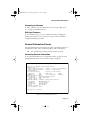
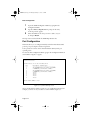
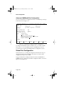
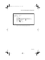
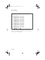
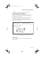
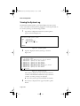
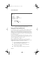
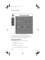
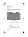
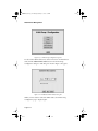
Management Interface
After you connect to the Local Management Interface using either an out-ofband Console connection or an in-band Telnet connection as described in
“Configuring for Management”, the Main Menu appears, as in Figure 2-3.
=================================================================
IntraChassis 9000 Local Management System Version 1.000
Compiled Date: May 7 1999 15:33:24
Asante Technologies, Inc.
Copyright (c) 1999 Asante Technologies, Inc.
=================================================================
Main Menu
<Cmd>
g
c
s
<Description>
General Information
Configuration
Statistics
Command>
Figure 2-3 Local Management Main menu
From the Main Menu, you can access three submenus:
❑
General Information — 2-19
❑
Configuration — 2-20
❑
Statistics — 4-1
If you are using Telnet, a fourth option, for closing the connection, will also be
available.
Page 2-18
GLXY9.book Page 19 Thursday, February 17, 2000 3:04 PM
General Information Screen
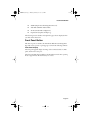
Accessing a Submenu
To access a submenu, type the command letter of the corresponding option
(e.g., type g for General Information).
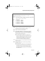
Exiting a Submenu
To exit a submenu, type q. To exit a command line without changing the
configuration setting (e.g., the “Set Password” option in the User Interface
Configuration Menu), press ctrl-c.
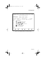
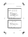
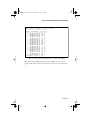
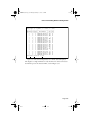
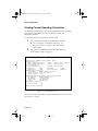
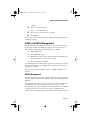
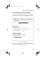
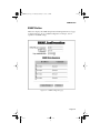
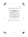
General Information Screen
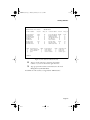
The General Information Screen displays the current operating information of
the IntraChassis 9000, such as its name, IP address, and boot information.
◆
Note: The information displayed on this screen is read-only.
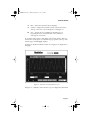
Accessing General Information
To view General Information for your IntraChassis 9000, type g in the Local
Management Main menu. A screen similar to Figure 2-4 appears.
IntraChassis 9000 General Information
System up for: 000days, 21hrs, 45mins, 45secs
Software Version
Bank 1 Image Version/Date: 1.10/Dec 7 1999 12:14:38 (Running)
Bank 2 Image Version/Date: 1.10/Dec 7 1999 11:54:14
System Information
Prom Image Ver/Date:
1.01/Sep 8 1999 15:59:14
DRAM Size:
4MB
Flash Size:
2.0MB
EEPROM Size:
32KB
Console Baud Rate:
9600 bps
Administration Information
System Name:
Asante IntraChassis Switch
System Location: ZLabs Head Office
System Contact: CLB
System MAC Address, IP Address, Subnet Mask and Router
MAC Address:
00:00:94:8E:F3:7B
IP Address:
192.168.54.240
Subnet Mask:
255.255.255.0
Router:
192.168.54.2
Bootstrap Configuration
Boot Load Mode: LOCAL
Press any key to continue...
Figure 2-4 General Information Screen
Page 2-19
GLXY9.book Page 20 Thursday, February 17, 2000 3:04 PM
Installation and Set-up
◆
Note: For a description of each parameter on the General
Information Screen, see “Viewing Current Operating Information” on page 3-48.
To exit the General Information Screen, press any key on your keyboard.
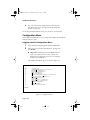
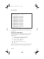
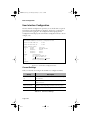
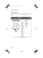
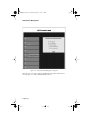
Configuration Menu
The Configuration Menu allows you to manage and configure the IntraChassis
9000 and each of its ports.
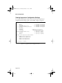
Logging into the Configuration Menu
1
2
Type c from the Local Management Interface Main Menu.
Enter your password at the “Enter Password” prompt, then
press Return.
▲ Important: The default password is Asante. The password is case-sensitive; enter it exactly as shown. For
information on changing the password, see “Changing
the Password” in Chapter 3.
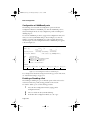
The Configuration Menu appears, as shown in Figure 2-5.
IntraChassis 9000 Configuration Menu
<Cmd>
a
i
b
n
p
d
f
r
l
u
s
t
v
q
<Description>
System Administration Configuration
System IP Configuration
Bootstrap Configuration
SNMP Configuration
Port Configuration
Unicast Forwarding Database Configuration
File Downloading Configuration
System Reset Options
System Log
User Interface Configuration
Spanning Tree Configuration
Security Management
VLAN Management
Return to previous Menu
Command>
Figure 2-5 Configuration Menu
Page 2-20
GLXY9.book Page 21 Thursday, February 17, 2000 3:04 PM
Configuration Menu
3
Type the command letter of the configuration option you
need to use. For example, type a for the System Administration Configuration menu.
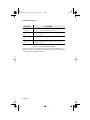
Configuration Menu Options
Table 2-5 on the next page describes each of the options in the Configuration
menu.
Menu Item
Description
System Administration Configuration
Displays and allows you to change the name, location, and contact
information for the IntraChassis 9000. See page 3-2.
System IP Configuration
Displays and allows changing the IP Address of the IntraChassis
9000. This address is for network access to the switch. See page 3-3.
Bootstrap Configuration
Allows you to change boot bank and method for loading switch software, or change downloading parameters. See page 3-5.
SNMP Configuration
Displays and allows you to change the SNMP (Simple Network
Management Protocol) parameters of the IntraChassis 9000; such as
read/write community strings. See page 3-11.
Port Configuration
Allows you to configure manually each of the switch’s ports for speed,
connection, link mode, and auto-negotiation. Also displays overall
port status. See page 3-14.
Unicast Forwarding Database Configuration
Allows you to display all of the forwarding database, or display it by
port or VLAN, either with or without showing IP addresses. Also lets
you search for MAC or IP addresses and lets you set the age-out time
for MAC addresses. See page 3-28.
Image File Downloading Configuration
Allows you to download an Image file for the purpose of upgrading
the IntraChassis 9000 software. See page 3-37.
System Reset Configuration
Allows you to reset the switch by a “warm” reboot, or arrange for an
automatic reset (up to 24 hours) in advance. See page 3-44.
System Log
Allows you to view a record of any major system events or errors that
have occurred on the IntraChassis 9000. See page 3-46
User Interface
Configuration
Allows you to set the idle time-out period and password when using
Console or Telnet access. See page 3-50.
Page 2-21
GLXY9.book Page 22 Thursday, February 17, 2000 3:04 PM
Installation and Set-up
Menu Item
Description
Spanning Tree
Configuration
Displays and allows you to change Spanning Tree parameters, to
make sure you prevent loops in network paths. See page 5-2.
Security Management
Allows you to use various features such as Duplicate IP traps, for port
security. See page 5-8.
VLAN Management
Allows you to set up virtual networks. See page 5-11
Return to Previous
Menu
Allows you to Exit the Configuration menu to the Local Management Interface menu.
Table 2-5
Configuration Menu Options
The first ten options for configuration are described in detail in Chapter 3,
“Basic Configuration” and the more advanced options are discussed in Chapter
5, the “Advanced Management” chapter.
Page 2-22
GLXY9.book Page 1 Thursday, February 17, 2000 3:04 PM
3
Basic Configuration
This chapter describes how to manage the IntraChassis 9000 using the out-ofband Console or in-band Telnet interface.
This chapter contains the following sections:
❑
Overview
❑
System Administration Configuration
❑
System IP Configuration
❑
Bootstrap Configuration
❑
SNMP Configuration
❑
Port Configuration
❑ Advanced Port Configuration
❑ Global Port Configuration
❑
Unicast Forwarding Database Configuration
❑
Image File Downloading Configuration
❑
System Reset Configuration
❑
Viewing the System Log
❑
Viewing Current Operating Information
❑
User Interface Configuration
Basic Configuration Overview
The IntraChassis 9000 Local Management Interface is a menu-driven
application which provides management and configuration support for the
IntraChassis 9000 and each of the ports in its different modules.
The Local Management Interface can be accessed via two methods:
❑
Out-of-band connection to the Console port
❑
In-band connection via Telnet (four sessions maximum).
Page 3-1
GLXY9.book Page 2 Thursday, February 17, 2000 3:04 PM
Basic Configuration
For details on accessing the Local Management Interface, see Chapter 2,
“Installation and Set-up”.
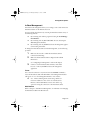
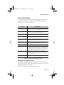
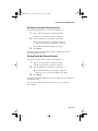
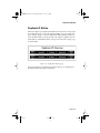
System Administration Configuration
This menu displays and allows you to change the IntraChassis 9000’s name,
location, and contact information.
To access the System Administration Configuration Menu, type a in the
Configuration Menu. A screen similar to Figure 3-1 appears.
IntraChassis 9000 System Admin. Configuration Menu
System Name:
System Location:
System Contact:
<Cmd>
n
l
c
q
Asante IntraChassis Switch
ZLabs Main Office
CLB
<Description>
Set System Name
Set System Location
Set System Contact Information
Return to Previous Menu
Command>
Figure 3-1 System Administration Configuration Menu
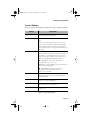
Current Settings
The following table describes each setting on the System Administration
Configuration Menu.
Setting
Description
System Name
The name of the IntraChassis 9000 (up to 64 characters, including spaces).
System Location
Place where you have installed the IntraChassis 9000 (up to 64
characters, including spaces).
System Contact
The name of the person or entity responsible for the IntraChassis
9000 (up to 64 characters, including spaces).
Table 3-1
Page 3-2
System Administration settings
GLXY9.book Page 3 Thursday, February 17, 2000 3:04 PM
System IP Configuration
Changing System Administration Info
To change the name, location, or contact information for the IntraChassis
9000, use the following procedure.
1
Open the System Administration Configuration Menu by
typing a in the Configuration Menu.
2
Type the command letter of the item to be changed in the
System Administration Configuration Menu.
3
Type the information at the prompt.
See Table 3-1 for a description of each parameter.
◆ Note: Each parameter is limited to 64 characters,
including spaces.
To cancel a selected option, press ctrl-c at the command
prompt.
4
Press Return.
The IntraChassis 9000 system administration information
changes take effect.
5
Type q to quit and return to the Configuration menu.
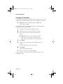
System IP Configuration
This menu displays and allows you to change the information needed to access
the IntraChassis 9000 over the network via in-band management.
To access the System IP Configuration Menu, type i in the Configuration
Menu. A screen similar to Figure 3-2 appears.
Page 3-3
GLXY9.book Page 4 Thursday, February 17, 2000 3:04 PM
Basic Configuration
IntraChassis 9000 System IP Configuration Menu
System
System
System
System
MAC Address:
IP Address:
Subnet Mask:
Default Router:
<Cmd>
i
m
r
n
q
00:00:92:CC:BB:AA
192.168.54.240 (intrach.asante.com)
255.255.255.0
192.168.54.2
<Description>
Set IP Address
Set Subnet Mask
Set Default Router
Set Domain Name Server
Return to Previous Menu
Command>
Figure 3-2 System IP Configuration Menu
▲
Important: By default, each address is set to 0.0.0.0.
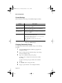
Current Settings
Table 3-2 describes each setting on the System IP Configuration menu.
Setting
Description
System IP Address
The IP (Internet Protocol) address of the IntraChassis 9000.
System Subnet Mask
The filter which determines how the IntraChassis 9000 IP address
is split into network and host portions.
System Default Router
The IP address of the default router for the IntraChassis 9000.
Table 3-2
System IP settings
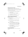
Changing System IP Information
To change the IP address, subnet mask, or default router of the IntraChassis
9000, use the following procedure.
1
Open the System IP Configuration Menu by typing i in the
Configuration Menu.
2
Type the command letter of the option you want to change.
Page 3-4
GLXY9.book Page 5 Thursday, February 17, 2000 3:04 PM
Bootstrap Configuration
3
Type the new address at the prompt.
See Table 3-2 for a description of each address.
▲ Important: follow the format:
number.number.number.number
To cancel a change, press ctrl-c at the command prompt.
4
Press Return.
The IP setting change for the IntraChassis 9000 takes effect.
5
Type q to quit and return to the Configuration Menu.
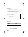
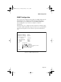
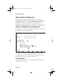
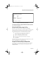
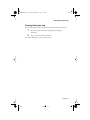
Bootstrap Configuration
This menu displays (and allows you to change) the bootstrap parameters used
for loading the software for the IntraChassis 9000 at startup, and for
downloading a new version of software when one is issued.To access the
Bootstrap Configuration Menu, type b in the Configuration Menu. If the
Load Mode is set to LOCAL, a screen similar to Figure 3-3 appears.
IntraChassis 9000 Bootstrap Configuration Menu
Bank 1 Image Version/Date:
Bank 2 Image Version/Date:
Load Mode:
Boot Bank:
<Cmd>
r
a
q
1.00B/May 3 1999 10:00:07 (Running)
1.00G/May 5 1999 17:32:18
Local
2
<Description>
Set Load Mode to REMOTE
Toggle Boot Bank
Return to previous menu
Command>
Figure 3-3 Local Bootstrap Configuration Menu
When the IntraChassis 9000 is powered on, it loads its software via one of two
methods: locally (via its internal flash memory which is the default setting) or
remotely over the network.
▲
Important: The default Load Mode setting for the IntraChassis 9000 is Local.
Page 3-5
GLXY9.book Page 6 Thursday, February 17, 2000 3:04 PM
Basic Configuration
Image Banks
The IntraChassis 9000 has two banks to store its runtime software. The banks
are referred to as bank 1 and bank 2.
Either of these banks may be the Boot Bank, which is the bank from which the
runtime code will be loaded the next time the IntraChassis 9000 is booted.
When downloading new runtime image codes, you may specify either of the
two banks as the Destination Bank in which the new code will be loaded.
Page 3-6
GLXY9.book Page 7 Thursday, February 17, 2000 3:04 PM
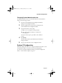
Bootstrap Configuration
Loading Software Locally
The IntraChassis 9000 will always boot locally unless you set it to boot load
remotely. It would then download the new image code and reset to load locally.
1
Open the Bootstrap Configuration Menu by typing b in the
Configuration Menu.
2
Type a in the Bootstrap Configuration Menu if you need to
toggle the Boot Bank setting for the next boot. Typically,
you will want to set the boot bank to be the one on which
the latest version of the Image resides.
The IntraChassis 9000 is set to load software locally from its flash memory. This
occurs whenever the unit is powered on or reset.
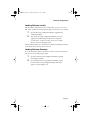
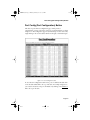
Loading Software Remotely
To set the IntraChassis 9000 to download its software over the network from a
remote server, use the following procedure.
1
Open the Local Bootstrap Configuration Menu by typing b
in Configuration Menu.
2
Open the Remote Bootstrap Configuration Menu by typing
r in the Local Bootstrap Configuration Menu. The menu
appears, as shown in Figure 3-4.
Page 3-7
GLXY9.book Page 8 Thursday, February 17, 2000 3:04 PM
Basic Configuration
IntraChassis 9000 Bootstrap Configuration Menu
Bank 1 Image Version/Date:
Bank 2 Image Version/Date:
Load Mode:
Boot Mode:
Boot Server IP:
Boot File Name:
Retry Count:
Boot Bank:
<Cmd>
b
t
l
s
f
c
a
q
1.10J/Dec 7 1999 12:14:38 (Running)
1.00G/May 5 1999 17:32:18
Remote
TFTP only
192.168.54.150
c:\base\newcrc.ima
5
1
<Description>
Set Boot Mode to BOOTP-TFTP
Set Boot Mode to TFTP only
Set Load Mode to LOCAL
Set Boot Server IP Address
Set Boot File Name
Set Remote Boot Retry Count
Toggle Boot Bank
Return to Previous Menu
Command>
Figure 3-4 Remote Bootstrap Configuration Menu
Page 3-8
GLXY9.book Page 9 Thursday, February 17, 2000 3:04 PM
Bootstrap Configuration
Current Settings
Table 3-3 explains each setting on the Remote Bootstrap Configuration Menu.
Setting
Description
Running Image Version/
Date
The version and compilation date of runtime code that is currently running on the IntraChassis 9000.
Load Mode
The current method for loading software for the IntraChassis
9000.
Remote — Loads the image file from a server on the network.
Local — Executes the software image file from the IntraChassis
9000’s internal flash memory (default setting; the IntraChassis
9000 automatically reverts to this setting after downloading a new
software file).
Boot Mode
The method for requesting the image file from the network. This
option is available only if you have selected Remote Load Mode.
BootP-TFTP — Sets the IntraChassis 9000 to request an IP
address from a BootP server AND to download the software’s
image file through TFTP (Trivial File Transfer Protocol).
▲ Important: To use this option, the IntraChassis 9000 IP address must be set to 0.0.0.0.
TFTP ONLY — Sets the IntraChassis 9000 to only download the
software image file through TFTP.
▲ Important: To use this option, the switch must
already have an assigned IP address and the Load
Mode must be set to Remote.
Boot Server IP
The Internet Protocol (IP) address of the TFTP server providing
the TFTP capabilities on your network. Not Available if Boot
Mode is BootP-TFTP.
Boot File Name
The name of the file you are going to request for download. Not
available if boot mode is BootP/TFTP.
Retry Count
Number of attempts the IntraChassis 9000 makes to download
the image file if errors occur. The default is 5.
Boot Bank
Number of the destination bank for the image file you are downloading (1 or 2).
Table 3-3
Bootstrap Settings
Page 3-9
GLXY9.book Page 10 Thursday, February 17, 2000 3:04 PM
Basic Configuration
3
Type b to set the Boot Mode to BootP-TFTP, or type t to
set Boot Mode to TFTP only. If you choose BootP-TFTP
mode, the options for setting the IP Address of the TFTP
server and the Boot File Name become unavailable; in this
case, skip Steps 4-7 and go on to Step 8.
4
Type s in the Bootstrap Configuration Menu, to select the
option Set Boot Server IP Address.
5
At the prompt, type the IP address of the remote boot server
which contains the switch’s software image file. Then press
Return. The Bootstrap Configuration Menu appears.
6
7
8
Type f to select the option Set Boot File Name.
Type the software’s file name/network path at the prompt.
Press Return.
◆ Note: If you decide to use Local Load Mode rather
than Remote, type l. The Local Bootstrap Configuration Menu appears, as shown in Figure 3-3.
The IntraChassis 9000 is now set to download its software remotely from the
network. This will occur the next time the unit is powered on or reset.
Page 3-10
GLXY9.book Page 11 Thursday, February 17, 2000 3:04 PM
SNMP Configuration
SNMP Configuration
The s option in the Configuration menu displays the SNMP (Simple Network
Management Protocol) Configuration Menu of the IntraChassis 9000, as
shown in Figure 3-5. For further details on using SNMP and RMON for
remote management of your network, see Chapter 5, "Advanced
Management".
This menu allows you to configure the unit’s read and write community strings,
and enable or disable authentication traps. It also allows you to specify which of
your network management stations will receive traps from the IntraChassis
9000.
IntraChassis 9000 SNMP Configuration Menu
SNMP Read Community:
SNMP Write Community:
Authentication Trap:
public
private
Enabled
SNMP Trap Receivers:
IP Address
1. 192.168.54.150
2. 192.168.54.110
3. <EMPTY>
4. <EMPTY>
Community
private
Sarah
<EMPTY>
<EMPTY>
<Cmd>
r
w
t
a
d
q
<Description>
Set SNMP Read Community
Set SNMP Write Communtiy
Toggle Trap Authentication Enable/Disable
Add/Update SNMP Trap Receiver
Delete SNMP Trap Receiver
Return to Previous Menu
Command>
Figure 3-5 SNMP Configuration menu
Page 3-11
GLXY9.book Page 12 Thursday, February 17, 2000 3:04 PM
Basic Configuration
Current Settings
Table 3-4 describes each setting on the SNMP Configuration Menu.
Setting
Description
SNMP Read Community
The string that defines access rights for reading SNMP data
objects. The default is public.
SNMP Write Community
The string that defines access rights for writing SNMP data
objects. The default is private.
Trap Authentication
The status of the SNMP agent for authentication trap generation.
The default is disabled.
SNMP Trap Receivers
The IP addresses of the network management stations that can
receive traps from the IntraChassis 9000.
Normally, these addresses are the same as your network management software systems’ IP addresses.
▲ Important: A maximum of four trap receivers
is allowed.
Table 3-4
SNMP Settings
Changing Community Strings
To change the IntraChassis 9000 community strings, use the following
procedure.
1
Open the SNMP Configuration Menu by typing n in the
Configuration Menu.
2
Type r to change the read community string or w to change
the write community string.
3
Type a new community string at the prompt.
See Table 3-4 for a description of read and write community strings.
To cancel a selected option, press ctrl-c at the command
prompt.
4
5
Press Return. The new string takes effect.
Type q to quit and return to the Configuration Menu.
Page 3-12
GLXY9.book Page 13 Thursday, February 17, 2000 3:04 PM
SNMP Configuration
Enabling Authentication Traps
The IntraChassis 9000 can be set to generate authentication traps.
Authentication traps are messages sent across the network to an SNMP network
management station. They alert you when someone attempts to read or change
data without the proper community string.
To set the IntraChassis 9000 to generate traps, use the following procedure.
1
Open the SNMP Configuration Menu by typing n in the
Configuration Menu.
2
Type a to toggle trap authentication to enabled.
To cancel the change, press ctrl-c at the command prompt.
3
4
Press Return. The new setting takes effect.
Type q to quit and return to the Configuration Menu.
Adding or Updating a Trap Receiver
Trap receivers are network management stations designated to receive traps
from the IntraChassis 9000.
▲
Important: The maximum number of trap receivers that
can be set is four.
To add or update a trap receiver entry, use the following procedure.
1
Open the SNMP Configuration Menu by typing n in the
Configuration Menu.
2
3
Type a to Add a Trap Receiver. An IP prompt appears.
Type the new or updated IP address of the network management station you want to receive traps, then press Return.
To cancel an entry, press ctrl-c at the command prompt.
4
Type the trap receiver’s community string at the prompt for
it, then press Return again.
The trap receiver entry is added or updated. Type q to
return to the Configuration Menu.
Deleting a Trap Receiver
Use the following procedure to delete a trap receiver you have previously
designated.
Page 3-13
GLXY9.book Page 14 Thursday, February 17, 2000 3:04 PM
Basic Configuration
1
Open the SNMP Configuration Menu by typing n in the
Configuration Menu.
2
Type d to Delete a Trap Receiver. A prompt for the entry
of the trap receiver appears.
3
Enter the number of the entry you want to delete (1,2,3, or
4) and press Return.
The trap receiver is deleted from the SNMP Trap Receivers list.
Port Configuration
This menu allows you to configure manually each of the IntraChassis 9000’s
ports for port speed, duplex, and auto-negotiation.
It also provides an overview of the entire IntraChassis 9000 system’s port
operating status.
To access the Port Configuration Menu, type p in the Configuration Menu. A
screen similar to Figure 3-6 appears.
System Module Map
=================
Please select one of the following slots
Slot
---1
2
3
4
5
6
7
8
9
Description (Module Type)
-------------------------------------24 10/100BaseTX ports Module (24-100TX)
2 1000BaseX ports Module (2-GBIC)
24 10/100BaseTX ports Module (24-100TX)
2 1000BaseX ports Module (2-GBIC)
<none>
<none>
<none>
<none>
<none>
Enter Module Number (1-8)>
Figure 3-6 System module map screen
Choose the module for which you want see a port configuration menu. If, for
example, you chose slot 1, you would see a screen similar to Figure 3-7.
Page 3-14
GLXY9.book Page 15 Thursday, February 17, 2000 3:04 PM
Port Configuration
IntraChassis 9000 Basic Port Configuration MenuModule Type: (24-100TX)
Module: [1]
Port: [1]
1
8 9
16 17
24
======== ======== ========
Operating Status:
+------- -------- -------Auto Negotiation:
******** ******** ********
Link Speed/Duplex: Fhhhhhhh hhhhhhhh hhhhhhhh
Port Status:
Auto-Neg:
<Cmd>
h
t
u
l
d
o
r
a
g
q
Enabled
Link Status: Up
(24-100TX)
Enabled [ABCD] Link Speed: 10Mbps (Half Duplex)
<Description>
Help for legends
Toggle Port Status Enable/Disable
Toggle Auto-Negotiation/Manual
Toggle 10M/100M bps Link Speed
Toggle Half/Full Duplex
Modify Auto-Negotiation Advertisement
Restart Auto-Negotiation
Advanced Port Configuration
Global Port Configuration
Return to Previous Menu
Command>
Select module Next module Prev module Select port Next port Prev port
Figure 3-7 Port Configuration Menu for 10/100BaseTX modules
Page 3-15
GLXY9.book Page 16 Thursday, February 17, 2000 3:04 PM
Basic Configuration
Viewing Legends for Configuration Settings
To see legends explaining the symbols used for both the basic and global port
configuration menu settings, type h. A screen similar to Figure 3-8 appears.
Legends for port status:
X
D
d
B
S
R
+
Legends for port speed & duplex:
-
Absent
f - 10 Mbps & full duplex
Link down
F - 100 Mbps & full duplex
Disabled by Mgmt Action
h - 10 Mbps & half duplex
Disabled by Security Violation
H - 100 Mbps & half duplex
Blocking
Listening
Learning
Legends for port priority:
Forwarding
(The range is from 0 to 3)
0 - priority 0 (lowest)
Legends for Enable/Disable State:
1 - priority 1 (lower)
- - Disabled
2 - priority 2 (higher)
* - Enabled
3 - priority 3 (highest)
Legends for Auto-Negotiation Advertisement:
A
B
C
D
-
100Base-TX full duplex mode
100Base-TX half duplex mode
10Base-T full duplex mode
10Base-T half duplex mode
Press any key to continue...
Figure 3-8
Page 3-16
Legends for all Port Configuration menus
GLXY9.book Page 17 Thursday, February 17, 2000 3:04 PM
Port Configuration
Current Port Settings
The current module and port for which statistics are displayed is shown in the
top right corner of the Port Configuration menu. Table 3-5 describes each
setting on the Port Configuration menu.
Setting
Description
Module Number
The number of the module of which the selected port is a member.
Module Type
Code for the type of module: 24-100TX, or 2-GBIC: See
Figure 3-6 for the full names of each module type.
Port Number
The number of the port for which parameters are shown.
Operating Status
This field displays status symbols for each of the current module’s
ports. See the legend in Figure 3-8 for details.
Auto Negotiation
This field displays disabled/enabled symbols for each of the current ports. See the legend in Figure 3-8 for details.
Link Speed/Duplex
This field displays speed/duplex setting symbols for each of the
current ports. See the legend in Figure 3-8 for details.
Port Status
Tells whether the selected port is enabled or disabled.
Link Status
Tells whether the selected port’s link is up or down. ‘Up’ indicates
a network device is connected to the port. ‘Down’ indicates that
either a device isn’t connected or that the device is powered down.
The port’s link speed and duplex mode are in parentheses.
Auto-Neg
Tells whether auto-negotiation is enabled or disabled for the
selected port, and for which modes, A, B, C, or D. See the legend
in Figure 3-8 for details.
Link Speed
Tells the speed and duplex mode of the port’s current link.
Table 3-5
Port Configuration Menu settings
Enabling or Disabling a Port
The enabling or disabling of a port is a manual operation that can be used to
isolate network devices possibly causing problems on the network or to prevent
unauthorized use of a port or station.
To enable or disable a port, use the following procedure.
Page 3-17
GLXY9.book Page 18 Thursday, February 17, 2000 3:04 PM
Basic Configuration
1
Access the Port Configuration menu by typing p in the
Configuration menu.
2
3
Choose a module in the System Module Map.
4
In the Basic Port Configuration Menu, use s, n, or p to
select the port you want to enable or disable.
Type t to toggle the port’s connection to either enabled or
disabled status, as desired.
The port’s status is changed immediately, and it is reflected in the Port Status
displayed near the top of the Port Configuration menu, and the Operating
Status symbol shown for the port.
Configuring Auto-negotiation
Auto-negotiation is a feature of the Fast Ethernet standard that enables two
devices on a common segment to communicate their transmission speed
capabilities. This feature allows the devices to determine and use their highest
common speed and best communication parameters.
▲
Important: By default, all of the ports are set to Auto-negotiation, as shown in Figure 3-7.
To enable Auto-negotiation, or return to manual-setting mode, use the
following procedure.
1
Access the Port Configuration menu by typing p in the
Configuration menu.
2
3
Choose a module in the System Module Map.
4
In the Basic Port Configuration Menu, use s, n, or p to
select the port for which you want to set the auto-negotiation mode.
Type u to toggle the port’s auto-negotiation mode to
enabled or to return it to manual.
The auto-negotiation status changes immediately, and is displayed on the Auto
Negotiation line near the top of the Port Configuration menu.
▲
Important: If you change the status of the port from Manual to Enabled you must type r to restart Auto-negotiation.
Page 3-18
GLXY9.book Page 19 Thursday, February 17, 2000 3:04 PM
Port Configuration
Configuring a Port Manually
If you have changed the Auto-negotiation status of a port to Manual, as
described in the previous section, you can toggle the link speed from 10Mbps to
100Mbps and back, and toggle the port from half to full duplex and back.
Toggling Port Link Speed
Use the following procedure to toggle the port’s link speed.
1
Access the Port Configuration menu by typing p in the
Configuration menu.
2
3
Choose a module in the System Module Map.
4
In the Basic Port Configuration Menu, use s, n, or p to
select the port for which you want to set the link speed.
Type l to toggle the port’s link speed.
The link speed is changed immediately, and the change is reflected on the Link
Speed line near the top of the Port Configuration menu.
Toggling Half to Full Duplex
Half duplex mode allows transmission in two directions on the same channel,
but only in one direction at a time. Full duplex mode allows transmission in
two directions on the same channel at the same time.
▲
Important: To use full duplex mode, the device to which
the port is connected must support and be configured for
duplex mode.
Use the following procedure to change the duplex mode setting for a port that is
in Manual status.
1
Access the Port Configuration menu by typing p in the
Configuration menu.
2
3
Choose a module in the System Module Map.
4
In the Basic Port Configuration Menu, use s, n, or p to
select the port for which you want to set the duplex mode.
Type d to toggle the port’s duplex mode.
The change in mode is reflected immediately in the Link Speed/Duplex line
near the top of the Port Configuration menu.
Page 3-19
GLXY9.book Page 20 Thursday, February 17, 2000 3:04 PM
Basic Configuration
Configuration of 1000BaseX ports
The following sections describe the configuration options in the Port
Configuration Menu for a 1000BaseX port. Since the 1000BaseX ports are
always in full duplex mode, the only configuration possible is enabling and
disabling the port.
To access the 1000BaseX port menu, type p in the Configuration menu, and
when you see the System Module Map, as shown in Figure 3-6, enter the
number of a module with 1000BaseX ports (such as module 2 in the map
shown in Figure 3-6). The Configuration menu for 1000BaseX ports appears,
as shown in Figure 3-9.
IntraChassis 9000 Basic Port Configuration Menu Module Type: (2-GBIC)
Module: [1]
Port: [1]
Port
1
Port
2
===========
===========
Operating Status:
SX-LinkUp (Forwarding) SX-LinkDown
Port Status: Enabled
<Cmd>
h
t
a
g
q
Link Status: Up [1000Mbps-Full]
<Description>
Help for legends
Toggle Port Status Enable/Disable
Advanced Port Configuration
Global Port Configuration
Return to Previous Menu
Command>
Select module Next module Prev module Select port Next port Prev port
Figure 3-9 Port Configuration menu for 1000BaseX ports
For a description of the current settings shown in the top portion of the screen,
see “Current Port Settings” on page 3-17.
Enabling or Disabling a Port
The enabling or disabling of a port is a manual operation that can be used to
isolate network devices possibly causing problems on the network.
To enable or disable a port, use the following procedure.
1
Access the Port Configuration menu by typing p in the
Configuration menu.
2
3
Choose a module in the System Module Map.
In the Basic Port Configuration Menu, use s, n, or p to
Page 3-20
GLXY9.book Page 21 Thursday, February 17, 2000 3:04 PM
Port Configuration
select the port you want to enable or disable.
4
Type t to toggle the port’s connection to either enabled or
disabled status, as desired.
The port’s status is changed immediately, and it is reflected in the Port Status
displayed near the top of the Port Configuration menu.
Page 3-21
GLXY9.book Page 22 Thursday, February 17, 2000 3:04 PM
Basic Configuration
Advanced Port Configuration
The Advanced Port Configuration menu allows you to control the port
broadcast and multicast rate, to enable or disable 802.3x flow control, and to set
the default priority of the port. To access the Advanced Port Configuration
menu, first access either the 10/100BaseTX or the 1000BaseX Port
Configuration menu, as described earlier in this chapter, then type a to see the
Advanced Port Configuration menu, as shown in Figure 3-10 and Figure 3-11.
Advanced 10/100BaseTX Port Configuration
The following sections explain the configuration options in the Advanced Port
Configuration menu for 10/100BaseTX ports.
IntraChassis 9000 Advanced Port Configuration Menu
Module: [1]
Operating Status:
Flow Ctrl:
Priority:
Port:
1
8
========
+------*------10001111
Max. Broadcast Rate:
Max. Multicast Rate:
802.3x Flow Control:
Port Default Priority:
<Cmd>
h
r
f
i
q
[1]
9
16
========
--------------11111122
Module Type: (24-100TX)
17
24
========
--------------23333333
N/A
N/A
Enabled
1
<Description>
Help for legends
Set Max. Broadcast/Multicast Rate
Toggle 802.3x Flow Control Enable/Disable
Set Port Default Priority
Return to Previous Menu
Command>
Select module Next module Prev module Select port Next port Prev port
Figure 3-10 Advanced Port Configuration menu - 10/100BaseTX port
For a legend of the symbols used for the flow control and port priority table,
type h and you will see the screen displayed in Figure 3-8.
Current Settings
The settings shown in the top portion of the Advanced Port Configuration
menu are described in Table 3-6.
Page 3-22
GLXY9.book Page 23 Thursday, February 17, 2000 3:04 PM
Advanced Port Configuration
Setting
Description
Module Number
The number of the module of which the selected port is a member.
Module Type
Code for the type of module: 24-100TX, 2-GBIC, or 8-100FX:
See Figure 3-6 for the full names of each module type.
Operating Status
This field displays status symbols for each of the current module’s
ports. See the legend in Figure 3-8 for details.
Flow Control
The status of flow control for the current port.When enabled, it
allows you to control traffic and avoid congestion, such as when
the port is receiving too much traffic for the available buffer
resources.
Priority
The priority ranking for the port in regards to data transmission
during periods of peak or heavy on the network. Ports with higher
priority take precedence when there is traffic congestion.
Max. Broadcast Rate
The maximum number of packets per second that can be broadcast by the current port to the network
Max. Multicast Rate
The maximum number of packets that can be multicast to all or
selected ports on the network by the current port.
Table 3-6
Advanced Port Configuration menu settings
Setting the Maximum Broadcast or Multicast Rate
Use the following procedure to set a limit on how many packets may be either
broadcast or multicast from the current port.
1
Access the Port Configuration menu by typing p in the
Configuration menu.
2
3
Choose a module in the System Module Map.
4
Use s, n, or p to select the port for which you want to set
the broadcast or multicast rate.
5
Type r to set the maximum broadcast or multicast rate for
the selected port.
In the Basic Port Configuration Menu, type a to open the
Advanced Port Configuration menu.
Page 3-23
GLXY9.book Page 24 Thursday, February 17, 2000 3:04 PM
Basic Configuration
6
Enter the rate for broadcast or multicast and press Return.
The new maximum rate is displayed on the Advanced Port Configuration
menu.
Enabling or Disabling 802.3x Flow Control
Use the following procedure to control traffic and avoid congestion, such as
when there is a shortage of buffer resources for the port. Flow control is
accomplished by means of standard PAUSE control frames for each port,
independent of all others. The port must be configured to operate in Full
Duplex mode. If you enable flow control on a port which is overwhelmed (runlow in the buffer resources), that port will transmit PAUSE frames; the link
partner will obey the PAUSE frame. When the low-resource situation is
relieved, the port sends out PAUSE frames with zero time value to un-pause the
end-station. To enable flow control, first access the Port Configuration menu by
typing p in the Configuration menu, then take the following steps.
1
2
Choose a module in the System Module Map.
3
Use s, n, or p to select the port for which you want to
enable or disable flow control.
4
Type f to toggle flow control for the selected port.
In the Basic Port Configuration Menu, type a to open the
Advanced Port Configuration menu.
The flow control symbol for the selected port reflects its change in state, as does
the 802.3x Flow Control setting.
▲
Important: The link partner must be configured to recognize PAUSE frames when using this method of flow control.
Setting Port Default Priority
Use the following procedure to set a higher or lower priority for a port. This
priority setting determines the order in which the port forwards packets. Each
port is associated with a traffic class; 0 (zero) is the lowest, and the default
priority level, and 1 is the highest priority level.
1
Access the Port Configuration menu by typing p in the
Configuration menu.
2
Choose a module in the System Module Map.
Page 3-24
GLXY9.book Page 25 Thursday, February 17, 2000 3:04 PM
Advanced Port Configuration
3
In the Basic Port Configuration Menu, type a to open the
Advanced Port Configuration menu.
4
Use s, n, or p to select the port for which you want to set
the default priority.
5
6
Type i to set the priority for the selected port.
Enter the priority, from 0 or 1, and press Return.
The new default priority is shown on the Advanced Port Configuration menu.
Page 3-25
GLXY9.book Page 26 Thursday, February 17, 2000 3:04 PM
Basic Configuration
Advanced 1000BaseX Port Configuration
If you are in the Basic Port Configuration menu for a 1000BaseX port and type
a the menu shown in Figure 3-11.
IntraChassis 9000 Basic Port Configuration Menu Module Type: (2-GBIC)
Module: [1]
Port: [1]
Port
1
Port
2
===========
===========
Flow Ctrl:
SX-LinkUp (Forwarding) SX-LinkDown
Priority:
1
1
Max. Broadcast Rate:
Max. Multicast Rate:
802.3x Flow Control:
Port Default Priority:
<Cmd>
h
r
f
i
q
N/A
N/A
Enabled
1
<Description>
Help for legends
Set Max. Broadcast/Multicast Rate
Toggle 802.3x Flow Control Enable/Disable
Set Port Default Priority
Return to Previous Menu
Command>
Select module Next module Prev module Select port Next port Prev port
Figure 3-11 Advanced Port Configuration menu - 1000BaseX port
To change the maximum broadcast or multicast rate, or to enable or disable
flow control, or to set the default priority for a 1000BaseX port, use the
procedures in the “Advanced 10/100BaseTX Port Configuration” section.
Global Port Configuration
This menu allows you to change the configuration information for all ports
simultaneously. This feature is helpful in cases where you want the same
configuration for all ports in a module.
Type g in the Basic Port Configuration menu for either 10/100BaseTX or
1000BaseX ports to display the Global Port Configuration Menu, as shown in
Figure 3-12 and Figure 3-13.
Page 3-26
GLXY9.book Page 27 Thursday, February 17, 2000 3:04 PM
Global Port Configuration
IntraChassis 9000 Global Port
Module: [1]
1
8
========
Operating Status:
+------Auto Negotiation:
********
Link Speed/Duplex: Fhhhhhhh
Flow Ctrl:
*------Priority:
00001111
<Cmd>
h
t
u
l
d
o
r
f
i
q
Configuration MenuModule Type: (24-100TX)
9
16
========
-------********
hhhhhhhh
-------11111122
17
20
========
-------********
hhhhhhhh
-------22333333
<Description>
Help for legends
Select Global Ports Status Enable/Disable
Select Global Auto-Negotiation/Manual
Select Global 10M/100M bps Link Speed
Select Global Half/Full Duplex
Modify Global Auto-Negotiation Advertisement
Set Global Max. Broadcast/Multicast Rate
Toggle Global 802.3x Flow Control Enable/Disable
Set Global Port Devault Priority
Return to Previous Menu
Command>
Select module Next module Prev module
Figure 3-12 Global Port Configuration menu - 10/100BaseTX ports
IntraChassis 9000 Global Port Configuration MenuModule Type: (2-GBIC)
Module: [1]
Port
1 Port
2
=========== ===========
Operating Status:
SX-Enabled
SX-Enabled
Flow Ctrl:
Disabled
Disabled
Priority:
1
0
<Cmd>
h
t
r
f
i
q
<Description>
Help for legends
Select Global Port Status Enable/Disable
Set Global Max. Broadcast/Multicast Rate
Toggle Global 802.3x Flow Control Enable/Disable
Set Global Port Default Priority
Return to Previous Menu
Command>
Select module Next module Prev module
Figure 3-13 Global Port Configuration menu - 1000BaseX ports
Page 3-27
GLXY9.book Page 28 Thursday, February 17, 2000 3:04 PM
Basic Configuration
Use the procedures in the “Port Configuration” and “Advanced Port
Configuration” sections of this chapter. The same procedures are used for global
configuration, except that you do not need to choose a module and port to
configure. Notice that the advanced configuration options, such as enabling or
disabling flow control, are also included in the menu.
Unicast Forwarding Database Configuration
This menu allows the user to view and search for addresses in the IntraChassis
9000’s MAC Forwarding Table. It also provides options for displaying MAC
addresses and IP/MAC binding by individual port or by VLAN.
The MAC Forwarding Table is a table of node addresses that the IntraChassis
9000 automatically builds by “learning,” It performs this task by monitoring
the packets that pass through the IntraChassis 9000, checking the source and
destination addresses, and then recording the source address information in the
table.
The IntraChassis 9000 uses the information in this table to decide whether a
frame should be forwarded to a particular destination port or “flooded” to all
the ports other than the received port. Each entry consists of the MAC address
of the device and an identifier for the port on which it was received.
◆
Note: The MAC address table can hold a maximum of
8,192 entries.
When you type d in the Configuration menu, the Unicast Forwarding Database
Configuration menu appears, as shown in Figure 3-14.
Page 3-28
GLXY9.book Page 29 Thursday, February 17, 2000 3:04 PM
Unicast Forwarding Database Configuration
IntraChassis 9000 Unicast Forwarding Database Configuration Menu
Age-out Time:
MAC Address Count:
IP Address Count:
<Cmd>
a
p
v
m
i
t
q
300 sec.
33
21
<Description>
Display All Forwarding Database With/Without IP
Display Forwarding Database By Port With/Without IP
Display Forwarding Database by VLAN With/Without IP
Search for MAC Address
Search for IP Address
Set Age-Out Time
Return to Previous Menu
Command>
Figure 3-14 Unicast Forwarding Configuration menu
Page 3-29
GLXY9.book Page 30 Thursday, February 17, 2000 3:04 PM
Basic Configuration
Current Settings
Table 3-7 explains each setting on the Forwarding Database Configuration
Menu.
Setting
Description
Age-out Time
The number of seconds that addresses are retained in the table.
The default is 300 seconds. The range is from 10 to 1,000,000.
MAC Address Count
The number of entries currently in the MAC Address Table.
IP Address Count
The number of entries in the MAC Address Table that contain a
corresponding IP address.
Table 3-7
Forwarding Database Configuration menu settings
Displaying the Forwarding Database
You can display the Forwarding Database MAC address table with or without
IP addresses. Use the following procedure to view the table.
1
Open the Unicast Forwarding Database Configuration
Menu by typing d in the Configuration Menu.
2
Type either a, p, or v, depending on the range of MAC addresses
you want to view.
Type a to display the MAC address table with the MAC
addresses of all ports on the IntraChassis 9000.
Type p to specify a port, then see the MAC addresses for
that port only.
Type v to specify a VLAN, then see the MAC addresses for
the member ports of that VLAN only.
3
At the prompt which appears, type y to see IP addresses in
the display or type n to see the display without IP addresses,
then press Return. The selected display appears, as shown
in Figure 3-15.
Page 3-30
GLXY9.book Page 31 Thursday, February 17, 2000 3:04 PM
Unicast Forwarding Database Configuration
◆
Notes: The Age field in the MAC address tables indicates the
amount of time remaining before an entry ages out.
The Type field refers to the type of entry for the MAC
address of a device; the setting may be static, S (set by management, and will not age out), or dynamic, D (learned by
the switch, and will be aged out) or multiple, M (associated
with multiple IP addresses, as in the case of a router), or I
(management module’s MAC address).
The Self entry represents the IntraChassis 9000 MAC
address and IP address.
The Pri field refers to the priority setting for the port.
Entry Type: (D = Dynamic, S = Static, I = Self)
+------+----+----+-----------------+-----+---+
|Module|Port|Type| MAC Address | Age |Pri|
+------+----+----+-----------------+-----+---+
1
6
D 00:00:94:10:80:1D 159 0
1
6
D 00:E0:52:01:44:46 147 0
1
6
D 00:00:94:A2:DE:56 300 0
1
6
D 00:00:94:7A:CF:48
9 0
1
6
D 00:00:94:92:F1:A8 300 0
--- I 00:00:94:8E:F2:CC -- 0
1
6
D 00:00:94:5D:E0:41 285 0
1
6
D 00:00:94:5D:E1:9E 234 0
1
6
D 08:00:20:80:5E:9C 270 0
1
6
D 00:00:94:5D:E2:15 300 0
1
6
D 00:00:94:5D:E2:8D 276 0
1
6
D 00:00:94:10:E3:12 246 0
1
6
D 08:00:20:72:A0:1C 81 0
1
6
D 00:00:94:7B:02:C0 291 0
1
6
D 00:00:94:75:34:DE
3 0
1
6
D 00:00:94:75:31:DB 21 0
1
6
D 00:A0:CC:2C:60:CB 144 0
1
6
D 00:00:94:9A:2F:1C 150 0
1
6
D 00:00:94:75:2F:CF 297 0
Press Next, Previous, or Quit
Figure 3-15 Unicast Forwarding Database, all ports, without IP displayed
The first screen of the MAC address display for all ports shows the entries for
devices connected to the ports of the first module; if you scroll through the
database, you can see the entries for each port of each module. For example,
some MAC addresses for devices connected to port 6 of module 1 are shown in
Figure 3-15.
Page 3-31
GLXY9.book Page 32 Thursday, February 17, 2000 3:04 PM
Basic Configuration
Entry Type [T]: (D = Dynamic, S = Static, M = Multiple, I = Self)
+-+-+-+-----------------+----------------+
|M|P|T| MAC Address |
IP
|
+-+-+-+-----------------+----------------+
1 6 D 00:00:94:10:80:1D 199.35.192.185
1 6 D 00:E0:52:01:44:46 199.35.192.189
1 6 D 00:00:94:A2:DE:56 199.35.192.181
1 6 D 00:00:94:7A:CF:48 199.35.192.188
1 6 D 00:00:94:92:F1:A8 199.35.192.182
- - I 00:00:94:8E:F2:CC 199.35.192.187
1 6 D 00:00:94:5D:E0:41 199.35.192.183
1 6 D 00:00:94:5D:E1:9E 199.35.192.186
1 6 D 08:00:20:80:5E:9C 199.35.192.184
1 6 D 00:00:94:5D:E2:15 199.35.192.195
1 6 D 00:00:94:5D:E2:8D 199.35.192.199
1 6 D 00:00:94:10:E3:12 199.35.192.191
1 6 D 08:00:20:72:A0:1C 199.35.192.198
1 6 D 00:00:94:7B:02:C0 199.35.192.192
1 6 D 00:00:94:75:34:DE 199.35.192.197
1 6 D 00:00:94:75:31:DB 199.35.192.193
1 6 D 00:A0:CC:2C:60:CB 199.35.192.196
1 6 D 00:00:94:9A:2F:1C 199.35.192.194
1 6 D 00:00:94:75:2F:CF 199.35.192.175
Press Next, Previous, or Quit
Figure 3-16 Unicast Forwarding Database, all ports, with IP displayed
The Unicast Forwarding Database display does not show the age or priority of
the devices, as you can see in Figure 3-16.
Page 3-32
GLXY9.book Page 33 Thursday, February 17, 2000 3:04 PM
Unicast Forwarding Database Configuration
Module: [1] Port: [6]
Entry Type: (D = Dynamic, S = Static,I = Self)
+----+-----------------+-----+---+
|Type| MAC Address | Age |Pri|
+----+-----------------+-----+---+
D 00:00:94:10:80:1D 159 0
D 00:E0:52:01:44:46 147 0
D 00:00:94:A2:DE:56 300 0
D 00:00:94:7A:CF:48
9 0
D 00:00:94:92:F1:A8 300 0
D 00:00:94:8E:F2:CC
0 0
D 00:00:94:5D:E0:41 285 0
D 00:00:94:5D:E1:9E 234 0
D 08:00:20:80:5E:9C 270 0
D 00:00:94:5D:E2:15 300 0
D 00:00:94:5D:E2:8D 276 0
I 00:00:94:10:E3:12 -- 0
D 08:00:20:72:A0:1C 81 0
D 00:00:94:7B:02:C0 291 0
D 00:00:94:75:34:DE
3 0
D 00:00:94:75:31:DB 21 0
D 00:A0:CC:2C:60:CB 144 0
D 00:00:94:9A:2F:1C 150 0
D 00:00:94:75:2F:CF 297 0
Press Next, Previous, or Quit
Figure 3-17 Unicast Forwarding Database for a port, without IP displayed
The Unicast Forwarding Database display for a single port shows only the
entries for the devices connected to the selected port, as you can see in Figure 317.
Page 3-33
GLXY9.book Page 34 Thursday, February 17, 2000 3:04 PM
Basic Configuration
Module: [1] Port: [6]
Entry Type [T]: (D = Dynamic, S = Static, M = Multiple, I = Self)
+-+-+-+-----------------+----------------+
|M|P|T| MAC Address |
IP
|
+-+-+-+-----------------+----------------+
1 6 D 00:00:94:10:80:1D 199.35.192.185
1 6 D 00:E0:52:01:44:46 199.35.192.189
1 6 D 00:00:94:A2:DE:56 199.35.192.181
1 6 D 00:00:94:7A:CF:48 199.35.192.188
1 6 D 00:00:94:92:F1:A8 199.35.192.182
- - I 00:00:94:8E:F2:CC 199.35.192.187
1 6 D 00:00:94:5D:E0:41 199.35.192.183
1 6 D 00:00:94:5D:E1:9E 199.35.192.186
1 6 D 08:00:20:80:5E:9C 199.35.192.184
1 6 D 00:00:94:5D:E2:15 199.35.192.195
1 6 D 00:00:94:5D:E2:8D 199.35.192.199
1 6 D 00:00:94:10:E3:12 199.35.192.191
1 6 D 08:00:20:72:A0:1C 199.35.192.198
1 6 D 00:00:94:7B:02:C0 199.35.192.192
1 6 D 00:00:94:75:34:DE 199.35.192.197
1 6 D 00:00:94:75:31:DB 199.35.192.193
1 6 D 00:A0:CC:2C:60:CB 199.35.192.196
1 6 D 00:00:94:9A:2F:1C 199.35.192.194
1 6 D 00:00:94:75:2F:CF 199.35.192.175
Press Next, Previous, or Quit
Figure 3-18 Unicast Forwarding Database for a port, with IP displayed
The Unicast Forwarding Database display does not show the age or priority of
the devices, as you can see in Figure 3-18.
Page 3-34
GLXY9.book Page 35 Thursday, February 17, 2000 3:04 PM
Unicast Forwarding Database Configuration
VLAN ID: [1]
Entry Type: (D = Dynamic, S = Static, I = Self)
+------+----+----+-----------------+-----+---+
|Module|Port|Type| MAC Address | Age |Pri|
+------+----+----+-----------------+-----+---+
1
6
D 00:00:94:10:80:1D 159 0
1
6
D 00:E0:52:01:44:46 147 0
1
6
D 00:00:94:A2:DE:56 300 0
1
6
D 00:00:94:7A:CF:48
9 0
1
6
D 00:00:94:92:F1:A8 300 0
--- I 00:00:94:8E:F2:CC -- 0
1
6
D 00:00:94:5D:E0:41 285 0
1
6
D 00:00:94:5D:E1:9E 234 0
1
6
D 08:00:20:80:5E:9C 270 0
1
6
D 00:00:94:5D:E2:15 300 0
1
6
D 00:00:94:5D:E2:8D 276 0
1
6
D 00:00:94:10:E3:12 246 0
1
6
D 08:00:20:72:A0:1C 81 0
1
6
D 00:00:94:7B:02:C0 291 0
1
6
D 00:00:94:75:34:DE
3 0
1
6
D 00:00:94:75:31:DB 21 0
1
6
D 00:A0:CC:2C:60:CB 144 0
1
6
D 00:00:94:9A:2F:1C 150 0
1
6
D 00:00:94:75:2F:CF 297 0
Press Next, Previous, or Quit
Figure 3-19 Unicast Forwarding Database for a VLAN, without IP displayed
The display for a single VLAN shows only the entries for devices connected to
the member ports of the selected VLAN, as seen in Figure 3-19.
Page 3-35
GLXY9.book Page 36 Thursday, February 17, 2000 3:04 PM
Basic Configuration
VLAN ID: [1]
Entry Type [T]: (D = Dynamic, S = Static, M = Multiple, I = Self)
+-+-+-+-----------------+----------------+
|M|P|T| MAC Address |
IP
|
+-+-+-+-----------------+----------------+
1 6 D 00:00:94:10:80:1D 199.35.192.185
1 6 D 00:E0:52:01:44:46 199.35.192.189
1 6 D 00:00:94:A2:DE:56 199.35.192.181
1 6 D 00:00:94:7A:CF:48 199.35.192.188
1 6 D 00:00:94:92:F1:A8 199.35.192.182
- - I 00:00:94:8E:F2:CC 199.35.192.187
1 6 D 00:00:94:5D:E0:41 199.35.192.183
1 6 D 00:00:94:5D:E1:9E 199.35.192.186
1 6 D 08:00:20:80:5E:9C 199.35.192.184
1 6 D 00:00:94:5D:E2:15 199.35.192.195
1 6 D 00:00:94:5D:E2:8D 199.35.192.199
1 6 D 00:00:94:10:E3:12 199.35.192.191
1 6 D 08:00:20:72:A0:1C 199.35.192.198
1 6 D 00:00:94:7B:02:C0 199.35.192.192
1 6 D 00:00:94:75:34:DE 199.35.192.197
1 6 D 00:00:94:75:31:DB 199.35.192.193
1 6 D 00:A0:CC:2C:60:CB 199.35.192.196
1 6 D 00:00:94:9A:2F:1C 199.35.192.194
1 6 D 00:00:94:75:2F:CF 199.35.192.175
Press Next, Previous, or Quit
Figure 3-20 Unicast Forwarding Database for a VLAN, with IP displayed
The VLAN display does not show the age or priority of the devices, as you can
see in Figure 3-20.
Searching for a MAC Address
The MAC address table can be searched by MAC address or by IP address. To
search the MAC address table for a specific MAC or IP address, use the
following procedure.
1
Access the Unicast Forwarding Database Configuration
Menu by typing d in the Configuration menu.
2
Type m to search for a MAC address.
Type i to search for an IP address.
3
4
Type the MAC or IP address at the prompt.
Press return.
The address, if located is displayed, with its associated information, as shown in
Figure 3-21. If the address is not located, a message appears, stating this.
Page 3-36
GLXY9.book Page 37 Thursday, February 17, 2000 3:04 PM
Image File Downloading Configuration
The MAC Address Search Summary
==============================
Module:
1
Port:
6
Type:
Dynamic
Age:
200
Priority:
0
MAC Address: 00:00:94:11:12:13
IP Address: 192.203.54.111
press any key to continue...
Figure 3-21 MAC Address Search summary
The summary screen tells the location of the MAC or IP address; the module,
port, and the Domain Name. Configuration information, such as the priority,
type, and age are also displayed.
Setting the MAC Address Age-Out Time
This option sets the Age-Out Time for the MAC Forwarding Table.
The Age-Out Time is the number of seconds that addresses remain in the table
after being learned by the IntraChassis 9000. The default is 300 seconds.
Use the following procedure to set the MAC address Age-Out Time.
1
Access the Unicast Forwarding Database Configuration
Menu by typing d in the Configuration menu.
2
3
4
Type t to set the MAC Address Age-Out Time.
Enter the new Age-Out time (in seconds) at the prompt.
Press Return.
The MAC Address Age-Out Time is changed and is displayed at the top of the
Unicast Forwarding Database Configuration menu.
Image File Downloading Configuration
You can upgrade your IntraChassis 9000 system easily, using either TFTP or
X/Y/Z modem protocol and the Image File Downloading option of the
Configuration menu.
Page 3-37
GLXY9.book Page 38 Thursday, February 17, 2000 3:04 PM
Basic Configuration
Type f in the configuration menu to see the Image File Downloading
Configuration menu, as shown in Figure 3-22.
IntraChassis 9000 Image File Downloading Configuration Menu
<Cmd>
t
x
q
<Description>
TFTP Image File Downloading Configuration
X/Y/ZMODEM Image File Downloading Configuration
Return to Previous Menu
Command>
Figure 3-22 Image File Downloading Configuration menu
This menu lets you select the downloading protocol. Type t to download the
image file via TFTP, and type x to download using the X/Y/Z modem protocol.
The two subsections that follow describe downloading by each of the two
protocols.
When Asanté issues a new version of software for the IntraChassis 9000, you
can obtain it from the Asanté World Wide Web site or by contacting Asanté
Technical Support (see Appendix A, "Technical Support" for details).
Image Downloading Through TFTP
To download a new image file in-band through TFTP, type t in the Image
Download Configuration Menu (option g in Configuration Menu). A screen
similar to Figure 3-23 appears.
Page 3-38
GLXY9.book Page 39 Thursday, February 17, 2000 3:04 PM
Image File Downloading Configuration
IntraChassis 9000 TFTP File Downloading Menu
Bank 1 Image Version/Date
Bank 2 Image Version/Date
File Type:
Server IP:
File Name:
Retry Count:
Destination Bank:
<Cmd>
s
f
d
b
r
a
q
1.00T/May 07 1999 11:34:46
1.00U/Jul 29 1999 15:55:34 (Running)
Image
192.203.52.211
c:\base\main\gxrt.ima
5
1
<Description>
Set Server IP Address
Set File Name
Download Image File to Destination Bank
Download and Reboot from the Image File
Set Retry count
Toggle Destination Bank
Return to Previous Menu
Command>
Figure 3-23 TFTP Image Downloading menu
Current Settings
Table 3-8 describes each setting on the TFTP Image Downloading menu.
Setting
Description
Bank 1 Image Version/
Date
The version number and compilation date of runtime code that is
stored in memory Bank 1 on the IntraChassis 9000.
Bank 2 Image Version/
Date
The version number and compilation date of runtime code that is
stored in memory Bank 2 on the IntraChassis 9000. The (Running) designation indicates that the runtime code is currently running on this Bank. The same as the image file in the boot bank.
Server IP
IP address of network server containing software image file.
File Name
The software image file’s name and network path.
Retry Count
Number of attempts the switch will make to download image file.
Destination Bank
Number of the memory bank where the image file will download.
Table 3-8
TFTP Image Download menu settings
Page 3-39
GLXY9.book Page 40 Thursday, February 17, 2000 3:04 PM
Basic Configuration
Performing a Software Upgrade at Runtime
The software image file must be downloaded from a server on your network
that is running a TFTP server application.
▲
Important: Make sure the IntraChassis 9000 is configured
with an IP address (see “Changing System IP Information”
earlier in this chapter for details).
Use the following procedure to upgrade the IntraChassis 9000 software via
TFTP.
1
Access the TFTP Image File Downloading Configuration
menu by typing t in the Image File Downloading Configuration menu.
2
3
Type s to set the image server IP address.
4
5
Type f to set the image file name.
6
7
Type r to set the retry count.
8
Select the Destination Image Bank by using the a option. In
a typical situation, you will want to select the Bank on
which the software is not currently running, as shown in
Figure 3-23.
9
Type d to download the image file to the destination bank
(this option allows you to change the boot bank at a later
time and use the Reset menu to schedule a reset, at which
time the new software will be run).
At the prompt, enter the IP address of the server containing
the image file, then press Return.
At the prompt, enter the image file’s name and path, then
press Return.
At the prompt, enter the number of attempts the IntraChassis 9000 will make to download the image file, then press
Return.
OR
Type b to download the image file and reset the switch (this
option immediately boots the IntraChassis 9000 with the
new version of software).
Page 3-40
GLXY9.book Page 41 Thursday, February 17, 2000 3:04 PM
Image File Downloading Configuration
10
Type q to return to the Image File Downloading menu.
Serial Downloading Configuration
The X/Y/Z Modem Image file Downloading Configuration option lets you
download a new software image file for the IntraChassis 9000 without
interrupting the current operation.
To download a new image through the IntraChassis 9000 management
module’s serial (console) port, type x in the Image File Download
Configuration Menu. The X/Y/Z Modem Image File Downloading menu
appears, as shown in Figure 3-24.
IntraChassis 9000 X/Y/ZMODEM Image File Downloading Menu
Bank 1 Image Version/Date
Bank 2 Image Version/Date
Download Protocol:
Current Baud Rate:
Destination Bank:
<Cmd>
x
y
z
c
d
b
a
q
1.00T/May 07 1999 11:34:46
1.00U/Jul 29 1999 15:55:34 (Running)
ZMODEM
9600 bps
1
<Description>
Set download protocol to XMODEM
Set download protocol to YMODEM
Set download protocol to ZMODEM
Change Baud Rate Setting
Download Image File
Download and Boot Image File
Toggle Destination Bank
Return to Previous Menu
Command>
Figure 3-24 X/Y/Z Modem Image File Downloading menu
Current Settings
Table 3-9 describes the settings shown in the X/Y/Z Modem Image File
Downloading menu.
Page 3-41
GLXY9.book Page 42 Thursday, February 17, 2000 3:04 PM
Basic Configuration
Setting
Description
Bank 1 Image Version/
Date
The version number and compilation date of runtime code that is
stored in memory Bank 1 on the IntraChassis 9000.
Bank 2 Image Version/
Date
The version number and compilation date of runtime code that is
stored in memory Bank 2 on the IntraChassis 9000.The (Running) designation indicates that the runtime code is currently running on this Bank. The same as the image file in the boot bank.
Download Protocol
Current setting of the IntraChassis 9000’s serial download protocol.
Current Baud Rate
Transmission rate for the IntraChassis 9000’s serial port.
Destination Bank
Number of the memory bank where the image file will download.
Table 3-9
X/Y/Z Modem Image File Downloading settings
Performing a Software Upgrade
Use the following procedure to upgrade the IntraChassis 9000 software through
its serial (console) port.
1
In the Image File Download Configuration menu, type x to
open the X/Y/Z Modem Image File Downloading menu.
2
Type x, y, or z to select the corresponding modem protocol.
◆ Note: For information about these protocols, see the
manual for your communications software.
3
Type c to select the console baud rate. The Baud Rate Setting menu appears, as shown in Figure 3-25. The maximum
baud rate currently supported is 57,600 bps.
Page 3-42
GLXY9.book Page 43 Thursday, February 17, 2000 3:04 PM
Image File Downloading Configuration
Current Baud Rate: 9600 bps
Please select one from the following baud rate settings, or
press any other key to quit:
WARNING: The user must use the same baud rate setting of the terminal
after he/she confirms to change the baud rate setting of the
console in order to work correctly.
<Cmd>
a
b
c
d
e
f
g
<Description>
Set Baud Rate
Set Baud Rate
Set Baud Rate
Set Baud Rate
Set Baud Rate
Set Baud Rate
Set Baud Rate
to
to
to
to
to
to
to
1200 bps
2400 bps
4800 bps
9600 bps
19200 bps
38400 bps
57600 bps
Choice>
Figure 3-25 Baud Rate menu
4
Select one of the options in the above screen to select the
required baud rate and confirm it by typing y.
5
6
Type a to select the Destination Bank.
Use any serial communications software like Procomm Plus,
HyperTerminal, ZTerm, etc., to download the image file.
Follow the instruction manual of the serial communications
software for file transfer instructions.
◆ Note: The terminal on which serial communications
software is running must have the same baud rate as the
IntraChassis 9000 management module console. The
connection from the terminal to the switch Console
port must be an RS232C straight-through cable.
7
Type d to download to the selected destination bank or b to
download and reset.
8
Type q to return to the previous menu after performing a
successful download.
◆ Note: The baud rate default for Console management is
9600 bps. If you select a baud rate for the console port
other than 9600 bps, the screen will display garbage
data until the connected terminal is set to the same baud
rate as the console.
Page 3-43
GLXY9.book Page 44 Thursday, February 17, 2000 3:04 PM
Basic Configuration
System Reset Configuration
The System Reset Configuration Menu allows you to reset the IntraChassis
9000 by performing a “warm” reboot. It also allows you to schedule a reset up
to 24 hours in advance.
To reset the IntraChassis 9000, type r in the Configuration Menu. A screen
similar to Figure 3-26 appears.
IntraChassis 9000 System Reset Configuration Menu
Reset Status:
Reset Type:
Reset Countdown:
<Cmd>
s
c
r
d
i
q
Stop
Normal
1 sec.
<Description>
Schedule Reset Time
Cancel Reset
Reset System
Reset Switch to Factory Default
Reset Switch to Factory Default except IP and Bootstrap
Return to Previous Menu
Command>
Figure 3-26 System Reset Configuration menu
Current Options
Table 3-10 describes the settings shown in the Reset Configuration menu.
Option
Description
Schedule Reset Time
Number of seconds until the scheduled reset.
Cancel Reset
Stops the scheduled reset.
Reset Switch
Resets the IntraChassis 9000 immediately.
Reset Switch to Factory
Default
Resets the IntraChassis 9000 to the original factory settings.
Reset Switch to Factory
Default except IP &
Bootstrap
Resets the IntraChassis 9000 to the original factory settings without modifying the IP and Bootstrap configuration.
Table 3-10
Page 3-44
Reset Configuration options
GLXY9.book Page 45 Thursday, February 17, 2000 3:04 PM
System Reset Configuration
Resetting the IntraChassis 9000
To reset the IntraChassis 9000, use the following procedure.
1
Open the Reset Menu by typing r in the Configuration
Menu.
2
Type r to reset the IntraChassis 9000.
◆ Note: Typing d will reset the IntraChassis 9000 to the
factory default. Typing i will reset the IntraChassis 9000
to the factory default without affecting its IP and Bootstrap configuration.
3
Type y to confirm the reset,
OR type n to cancel the reset.
◆ Note: During the scheduled reset operation, you can see
the reset countdown increment by refreshing the screen.
Scheduling a Reset
You can schedule the IntraChassis 9000 to automatically perform a reset from
one second up to 24 hours (86,400 seconds) in advance.
To schedule a reset, use the following procedure.
1
Open the Reset Menu by typing r in the Configuration
Menu.
2
3
Type s to schedule a reset time (within the specified range).
Enter the number of seconds the IntraChassis 9000 will
wait before it automatically resets.
▲ Important: The maximum number of seconds that
can be entered is 86,400 (24 hours).
4
Press Return.
The IntraChassis 9000 will reset automatically after the number of seconds you
specified.
Page 3-45
GLXY9.book Page 46 Thursday, February 17, 2000 3:04 PM
Basic Configuration
Viewing the System Log
The IntraChassis 9000 System Log records and displays any major system
events on the switch, such as fatal errors, plugging in or removing a module, etc.
To view the system log, use the following procedure.
1
Type l in the Configuration menu. the System Log menu
appears, as shown in Figure 3-27.
IntraChassis 9000 System Log Menu
<Cmd>
l
c
q
<Description>
Display System Log
Clear System Log
Return to previous menu
Command>
Figure 3-27 System Log menu
2
Type d to display the current system log, as shown in
Figure 3-28.
IntraChassis 9000 System Log Summary
====================================================================
No. D: H: M: S Event
1. 000:00:00:00 Reset NVDB sections to factory default
2. 000:00:00:07 Spanning Tree Task Disabled
3. 000:00:32:53 Spanning Tree Task Enabled
4. 000:00:33:45 Spanning Tree Task Disabled
5. 000:00:41:11 Spanning Tree Task Enabled
6. 000:00:00:00 Reset NVDB section 0 to factory default
7. 000:00:32:51 Spanning Tree Task Disabled
8. 000:00:33:08 Spanning Tree Task Enabled
Quit Next Page
Figure 3-28 System Log Display
The system log displays any major system events that have
occurred on the IntraChassis 9000. If no major events have
occurred, “System up” messages are displayed.
◆ Note: The system Log holds a maximum of 64 entries.
3
Press any key to display the next page of System Log information.
Page 3-46
GLXY9.book Page 47 Thursday, February 17, 2000 3:04 PM
Viewing the System Log
Clearing the System Log
Use the following procedure to clear all entries from the current System Log.
1
Open the System Log menu by typing l in the Configuration menu.
2
Type c to clear the current System Log.
New entries will begin to accrue as events occur.
Page 3-47
GLXY9.book Page 48 Thursday, February 17, 2000 3:04 PM
Basic Configuration
Viewing Current Operating Information
The IntraChassis 9000 switch’s current operating information can be viewed by
accessing the General Information screen within the switch’s Local
Management Interface.
To view the current operating information of the switch:
1
Access the IntraChassis 9000 Local Management Interface.
◆ Note: See Chapter 2, "Installation and Set-up" for
instructions on how to connect to the Local Management Interface.
2
Type g in the Local Management Interface Main Menu. A
screen similar to Figure 3-29 appears.
IntraChassis 9000 General Information
System up for: 000days, 21hrs, 45mins, 45secs
Software Version
Bank 1 Image Version/Date: 1.10/Dec 7 1999 12:14:38 (Running)
Bank 2 Image Version/Date: 1.10/Dec 7 1999 11:54:14
System Information
Prom Image Ver/Date:
1.01/Sep 8 1999 15:59:14
DRAM Size:
4MB
Flash Size:
2.0MB
EEPROM Size:
32KB
Console Baud Rate:
9600 bps
Administration Information
System Name:
Asante IntraStack Switch
System Location: ZLabs Head Office
System Contact: CLB
System MAC Address, IP Address, Subnet Mask and Router
MAC Address:
00:00:94:8E:F3:7B
IP Address:
192.168.54.240
Subnet Mask:
255.255.255.0
Router:
192.168.54.2
Bootstrap Configuration
Boot Load Mode: LOCAL
Press any key to continue...
Figure 3-29 General Information Screen
Table 3-11 describes each parameter in the General Information screen. To exit
the screen, press any key.
Page 3-48
GLXY9.book Page 49 Thursday, February 17, 2000 3:04 PM
Viewing Current Operating Information
Setting
Description
System Up Time
The amount of time the system has been running since last reset
or power on.
Bank 1 Image Version/
Date
The version and compilation date of the runtime code that is
stored in Bank 1. (Running) indicates code is currently active.
Bank 2 Image Version/
Date
The version and compilation date of the runtime code that is
stored in Bank 2.
Prom Image Vers/Date
The version and compilation date of {{what?}}.
DRAM Size
The size in megabytes (MB) of the unit’s Dynamic Random
Access Memory.
EEPROM Size
The size in megabytes (MB) of the unit’s EEPROM.
Flash Size
The size, in MB, of the switch’s flash memory, or non-volatile
RAM.
Console Baud Rate
The current rate which data transfers to the console from the
IntraChassis 9000.
System Name
The name assigned to the IntraStack for network purposes.
System Location
The physical location of the IntraStack.
System Contact
Person responsible for configuration of the unit.
MAC Address
The hardware address of the IntraChassis 9000; this address cannot be changed
IP Address
The unit’s IP (Internet Protocol) address.
Subnet Mask
The IP subnet mask for the IntraChassis 9000.
Router
The IP address of the default gateway router to which the switch
belongs.
Boot Load Mode
The current method in use for loading the switch’s software.
Table 3-11
General Information settings
Page 3-49
GLXY9.book Page 50 Thursday, February 17, 2000 3:04 PM
Basic Configuration
User Interface Configuration
The User Interface Configuration option lets you set the idle time-out periods
for both the Console and Telnet user interfaces, and also lets you change the
password used for logging in to the configuration menu. Typing u in the
Configuration menu displays the User Interface Configuration menu, as shown
in Figure 3-30.
IntraChassis 9000 User Interface Configuration menu
Console UI Idle Time Out
Telnet UI Idle Time Out
Telnet Session Status:
Session
Status
1
Active
2
Inactive
3
Inactive
4
Inactive
<Cmnd>
c
t
p
q
5 min
5 min
Source IP
192.203.54.240
<none>
<none>
<none>
<Description>
Set Console UI Time Out
Set Telnet UI Time Out
Change Administrator Password
Return to previous menu
Command>
Figure 3-30 User Interface Configuration menu
Current Settings
Table 3-12 describes the settings in the UI Time-out Configuration Menu.
Setting
Description
Console UI Idle Timeout
Duration of time the Console will remain idle before returning to
the main menu.
Telnet UI Idle Time-out
Duration of time the console will remain idle before closing the
Telnet connection.
Telnet Session Status
Inactive or Active, depending on whether session is in progress.
Telnet Session Source IP
The IP address of the device being used for Telnet Management.
Table 3-12
Page 3-50
UI Time-out Settings
GLXY9.book Page 51 Thursday, February 17, 2000 3:04 PM
User Interface Configuration
Setting Console Idle Time-out Period
Use the following procedure to set the Console Idle Time-out.
1
Type c in the User Interface Configuration Menu.
A prompt for the number of minutes is displayed.
2
Enter the Idle Time-out in minutes at the prompt.
◆ Note: The default time-out is 5 minutes. Range for
time-out is 0-60 minutes (0 indicates no time-out).
To exit without making any changes, press ctrl-c.
3
Press Return.
The change of the Console Idle Time-out period is reflected in the User
Interface Configuration menu.
Setting Telnet Idle Time-out Period
Use the following procedure to change the Telnet Time-out.
1
Type t in the User Interface Configuration Menu.
A prompt for the number of minutes is displayed.
2
Enter the Idle Time-out in minutes at the prompt.
◆ Note: The default time-out is 5 minutes. Range for
time-out is 1-60. To exit without changes, press ctrl-c.
3
Press Return.
The change of the Telnet Idle Time-out period is reflected in the User Interface
Configuration menu.
After you have configured the desired time-outs, type q to return to the
previous menu.
Page 3-51
GLXY9.book Page 52 Thursday, February 17, 2000 3:04 PM
Basic Configuration
Changing the Password
Use this option to change the password that the user must enter to log in to the
configuration menu when using either the console or the Web server interface.
▲
Important: The factory default password is Asante. The
password is case-sensitive.
To change the current Local Management Interface or Web-based Interface
password, use the following procedure.
1
2
3
Type p in the User Interface Configuration Menu.
Type the password you have been using at the prompt.
Type a new password at the “Enter Current Password”
prompt.
▲ Important: The password is case-sensitive. The password can be up to a maximum of 20 characters in
length. The password characters can be any ASCII code.
4
5
Press Return.
Type the new password again at the confirmation password
prompt.
To cancel the change in password, type ctrl-c.
6
Press Return.
The password change takes effect.
7
Type q to return to the Configuration menu.
You will now need to enter the new password each time you log in to the
Configuration menu.
Page 3-52
GLXY9.book Page 1 Thursday, February 17, 2000 3:04 PM
4
Statistics
This chapter describes how to access the statistics for any module in the Galaxy
9000, and how to change your view of those statistics and the counters
displayed in it.
Viewing Statistics
Viewing statistics on a regular basis allows you to evaluate your network’s
performance. You can view current statistics for the IntraChassis 9000 on a perport basis by accessing the Statistics Menu in the Local Management Interface.
To view statistics use the following procedure.
1
Access the IntraChassis 9000 Local Management Interface,
as explained in Chapter 2, “Installation and Set-up”.
2
Type s in the Local Management Interface Main menu. The
System Module Map is displayed, as shown in Figure 4-1.
System Module Map
=================
Please select one of the following slots
Slot
---1
2
3
4
5
6
7
8
Description (Module Type)
------------------------------24 10/100BaseTX ports Module (24-100TX)
<none>
1000BaseX ports Module (2-GBIC)
<none>
24 10/100BaseTX ports Module (24-100TX)
<none>
<none>
<none>
Enter Module Number (1-8)>
Figure 4-1 Systems Module Map
3
Select the module for which you want to see statistics. The
Port Statistics Counters screen is displayed, as shown in
Figure 4-2.
Page 4-1
GLXY9.book Page 2 Thursday, February 17, 2000 3:04 PM
Statistics
IntraChassis 9000 Port Statistics Counters
Elapsed Time Since Up:
000:00:00:55
<Counter Name>
<Total>
Total RX Pkts
Dropped Pkts
Good Multicast
Oversize Pkts
Fragments
Collisions
64-Byte Pkts
128-255 Pkts
512-1023 Pkts
1474
185
6
0
0
0
283
12
0
<Cmd> <Description>
r
since reset
t
stop refresh
q
quit
Module: 2 Port: 1
<Avg./s> <Counter Name> <Total> <Avg./s>
26
3
0
0
0
0
5
0
0
Total RX Bytes 116246
Good Broadcast
57
Undersize Pkts
0
CRC/Align Errors 0
FCS Errors
0
Late Events
0
65-127 Pkts
1174
256-511 Pkts
5
1024-1518 Pkts
0
<Cmd> <Description>
x
next module
v
prev module
g
select module
<Cmd> <Description>
n
next port
p
prev port
s
select port
Command>
Figure 4-2 Port Statistics Counters since system up
4
Use the s command to select a port for which you want to
see the counters, or use n and p to find the port.
5
Use the g command to select a different module (group) in
which you want to select a port, or use x and v to find the
module.
6
Type t to stop the periodic updating of the counters, so you
can record what they are at that time.
7
Type r to see a display of the same counters, but accrued
since the last reset of the counters as shown in Figure 4-3.
Page 4-2
2113
1
0
0
0
0
21
0
0
GLXY9.book Page 3 Thursday, February 17, 2000 3:04 PM
Viewing Statistics
IntraChassis 9000 Port Statistics Counters
Elapsed Time Since Reset:
<Counter Name>
<Total>
Total RX Pkts
Dropped Pkts
Good Multicast
Oversize Pkts
Fragments
Collisions
64-Byte Pkts
128-255 Pkts
512-1023 Pkts
1474
185
6
0
0
0
283
12
0
Module: 2 Port: 1
000:00:00:55
<Avg./s> <Counter Name> <Total> <Avg./s>
26
3
0
0
0
0
5
0
0
Total RX Bytes 116246
Good Broadcast
57
Undersize Pkts
0
CRC/Align Errors 0
FCS Errors
0
Late Events
0
65-127 Pkts
1174
256-511 Pkts
5
1024-1518 Pkts
0
<Cmd> <Description>
<Cmd> <Description>
u
since system up
x
next module
t
stop refresh
v
prev module
q
quit
g
select module
2113
1
0
0
0
0
21
0
0
<Cmd> <Description>
n
next port
p
prev port
s
select port
Command>
Figure 4-3 Port Statistics Counters since reset
8
Type r to in the “since reset” screen reset the statistics
counters so you can see them accrue again from zero.
9
Type q to quit either statistics screen and return to the Local
Management System Main Menu.
For definitions of the counters, see Appendix B, "MIB Statistics".
Page 4-3
GLXY9.book Page 4 Thursday, February 17, 2000 3:04 PM
Statistics
Page 4-4
GLXY9.book Page 1 Thursday, February 17, 2000 3:04 PM
5
Advanced Management
This chapter describes advanced topics for SNMP and RMON management of
the IntraChassis 9000, Multicast Traffic Management, and configuration of
Spanning Tree Protocol parameters.
Spanning Tree Protocol
The Spanning Tree Protocol (STP) is a part of the IEEE 802.1D standard that
provides for redundancy in a bridged LAN by allowing multiple links between
points in the LAN.
Without the use of STP, multiple links in a bridged network will result in
bridging loops, which allow excess broadcast traffic which can bring down an
entire network.
Overview
The spanning tree protocol reduces a network with multiple, redundant
connections to one in which all points are connected (the protocol spans the
network), but in which there is only one path between any two points (the
paths are branched, as in a tree).
For example, in a large network with multiple paths, the same message will get
broadcast over the network through multiple paths, resulting in a great amount
of extra network traffic, and possibly, network downtime. This “closed path” or
“bridged loop” among the networks can also start an unending packet-passing
process.
▲
Important: To explain STP more effectively, the IntraChassis 9000 is described as a bridge for this section of the manual.
Page 5-1
GLXY9.book Page 2 Thursday, February 17, 2000 3:04 PM
Advanced Management
How It Works
All bridges on the network communicate with each other using special packets
called Bridge Protocol Data Units (BPDUs). The information exchanged in the
BPDUs enables bridges on the network to:
❑
Elect a single bridge to be the Root Bridge.
❑
Calculate the shortest path from each bridge to the root.
❑
Select a Designated Bridge on each segment which lies closest to the
root, and will forward traffic to the root.
❑
Select a port on each bridge to forward traffic to the root.
❑
Select the ports on each bridge which will forward traffic, and place
the redundant ports in blocking state.
Enabling and Disabling STP
The IntraChassis 9000 is shipped with Spanning Tree enabled on all ports. It
can be manually enabled or disabled following the instructions below
To enable or disable STP on your IntraChassis 9000, use the following
procedure.
1
2
Type c to open the Configuration Menu.
3
4
Type t to toggle STP to enabled or disabled.
Open the Spanning Tree Configuration Menu by typing s
in the Configuration Menu. See Figure 5-1.
If you select disabled, you are prompted to confirm the
change.
The STP status is changed. The status is displayed near the
top of the Spanning Tree Configuration menu.
Configuring Spanning Tree Parameters
To view the Spanning Tree Configuration menu, as shown in Figure 5-1, type s
in the Configuration menu.
Page 5-2
GLXY9.book Page 3 Thursday, February 17, 2000 3:04 PM
Spanning Tree Protocol
IntraChassis 9000 Spanning Tree Configuration Menu
STP Status:
Bridge ID:
Enabled
8000 0000948EF37B
Designated Root: 0001 00503EA8B000
Root Port:
Module: 3 Port: 8
Root Path Cost: 110
Hello Time:
Maximum Age:
Forward Delay:
<Cmd>
t
i
h
a
d
p
q
2 Sec.
20 Sec
15 Sec.
Bridge Hello Time:
Bridge Maximum Age:
Bridge Forward Delay:
2 Sec.
20 Sec.
15 Sec.
<Description>
Toggle STP Enable/Disable
Set Bridge Priority
Set Bridge Hello Time
Set Bridge Maximum Age
Set Bridge Forward Delay
Spanning Tree Port Configuration
Return to Previous Menu
Command>
Figure 5-1 Spanning Tree Configuration menu
Spanning Tree Parameters
The operation of the Spanning Tree Algorithm is governed by several
parameters. You should only attempt to set these parameters if you have
experience with the 802.1D specification.
Bridge Priority
Setting the Bridge Priority to a low value will make it more likely that the
current bridge will become the root bridge. If the current bridge is located
physically near the center of your network, you may wish to decrease the Bridge
Priority from its default value of 0x8000. If the current bridge is near the edge
of your network, it is best to leave the value of the Bridge Priority at its default.
Hello Time
This is the time period between BPDUs transmitted by each bridge.
Maximum Age
Each bridge should receive regular configuration BPDUs from the direction of
the root bridge. If the Maximum Age timer expires before the bridge receives
Page 5-3
GLXY9.book Page 4 Thursday, February 17, 2000 3:04 PM
Advanced Management
another BPDU, it assumes that a change in the topology has occurred and
begins recalculating the spanning tree.
Forward Delay
The Forward Delay parameter regulates the delay before each port begins
transmitting traffic after a recalculation of the spanning tree. If a port begins
forwarding traffic too soon, the network can be adversely affected. The
permitted range of the Forward Delay is 4 to 30 seconds.
◆
Note: The Hello Time, Maximum Age, and Forward Delay
are constrained by the following formula:
(Hello Time + 1) <= Maximum Age <= 2 x (Forward Delay -1)
In general, reducing the values of these timers will make the
spanning tree react faster in the case of changes in the topology, but may cause temporary loops as the tree stabilizes in a
new configuration. Lengthening the timers will make the
tree react more slowly to changes in configuration but will
make an unintended reconfiguration less likely. All of the
bridges in the tree must agree on the values of these timers,
so each bridge uses the ones advertised by the root.
Port Priority
If two ports are connected to the same segment, the manager can affect the
probability that either one will be chosen for inclusion in the tree by changing
this value.
Page 5-4
GLXY9.book Page 5 Thursday, February 17, 2000 3:04 PM
Spanning Tree Protocol
Current STP Settings
The following settings are displayed in the Spanning Tree Port Configuration
menu screen, as shown in Figure 5-2.
Setting
Description
STP Status
Whether spanning tree protocol is currently enabled or disabled.
Bridge ID
The Bridge Identifier of this bridge. The first part of the Bridge ID
is the Bridge Priority. (If the Bridge ID is shown as 8000
000094EE5080, the 8000 is the Bridge Priority. The remainder is
the MAC address of this bridge, which cannot be changed.).
Designated Root
The Bridge Identifier of the bridge that is currently the root bridge
for the spanning tree.
Root Port
The port this bridge will use to forward traffic to the root. If this
bridge is the root, the root port will be 0.
Root Path Cost
The cost as calculated by the spanning tree for messages to reach
the root. If this bridge is the root, the cost will be 0.
Hello Time
The value of the timer currently being used by the bridge.
Maximum Age
The value of the maximum age timer currently being used.
Forward Delay
The value of the forward delay timer currently being used.
Bridge Hello Time
The value that will be used by the spanning tree if this bridge
becomes the root bridge.
Bridge Maximum Age
The value that will be used by the spanning tree if this bridge
becomes the root bridge.
Bridge Forward Delay
The value that will be used by the spanning tree if this bridge
becomes the root bridge.
Spanning Tree Port Configuration
To set the Port Priority and Port Path Cost values for STP, access the Spanning
Tree Port Configuration menu shown in Figure 5-2 by typing p in the Spanning
Tree Configuration menu.
Page 5-5
GLXY9.book Page 6 Thursday, February 17, 2000 3:04 PM
Advanced Management
IntraChassis 9000 Spanning Tree Port Config. Menu
100TX)
Module: [1]
Port: [1]
Port
Port
Port
Port
Port
Port
Speed:
Status:
State:
MAC Address:
Priority:
Path Cost:
<Cmd>
i
c
q
Module Type: (24-
100 Mbps
Enabled
Forwarding
00:00:93:8F:E3:7C
0x80
10
<Description>
Set Port Priority
Set Port Path Cost
Return to Previous Menu
Command>
Figure 5-2 Spanning Tree Port Configuration menu
Setting Port Priority and Path Cost
Use the following procedure to set the STP Port Priority and Path Cost values.
The port priority is a Bridge Spanning Tree parameter that ranks each port.
When 2 or more ports have the same path cost, the STP selects the path with
the highest priority (lowest numerical value). By changing the priority of a port,
you can make it more or less likely to become the root port. The default value is
128, and the range is 0-255.
Port path cost is the Bridge Spanning Tree parameter that assigns a cost factor to
the port. The lower the assigned port path cost, the more likely the port is to be
accessed. The default value is a result of the equation
path cost = 1000/LAN speed (in Mbps)
Thus, for 10Mbps ports, the assigned default port path cost is 100, for
100Mbps ports the default port path cost is 10, and for 1000Mbps ports, the
assigned default port path cost is 1. The range is 1-65,535.
1
Access the Spanning Tree Port Configuration menu by typing p in the Spanning Tree Configuration menu.
2
Use the m, x, and v commands to select the module with
the port you want to configure.
3
Use the s, n, and p commands to select the port you want to
Page 5-6
GLXY9.book Page 7 Thursday, February 17, 2000 3:04 PM
SNMP and RMON Management
configure.
4
Type i to set the Port Priority.
Type c to set the Port Path Cost.
5
6
Enter a value for the setting you are making.
Press Return.
The new Port Priority or Port Path Cost is displayed in the Spanning Tree Port
Configuration menu.
SNMP and RMON Management
The SNMP (Simple Network Management Protocol) may be used to manage
the IntraChassis 9000. The SNMP agent supports database objects that are
defined in the following management information bases (MIBs):
❑
MIB II (RFC 1213)
❑
Bridge MIB (RFC 1493)
❑
RMON (RFC 1757) 4 groups - Ethernet Statistics, Ethernet History,
Alarm, and Events (See next section for details)
❑
Private IntraChassis 9000 MIB
Any SNMP-based network management application can be used to manage the
IntraChassis 9000. Refer to your SNMP software manual for information on
management of switches.
For details on console-based SNMP settings, see “SNMP Configuration” in
Chapter 3.
RMON Management
Remote Network Monitoring allows the network manager to gather data on the
network’s traffic for future retrieval. RMON is an Internet Standard defined in
RFC1757.
Using RMON, a network monitor (also called a probe) listens to traffic on the
network and gathers statistics which may be retrieved later by a network
management station using the Simple Network Management Protocol (SNMP)
as described in the previous section. The four groups of RMON that are
supported by the IntraChassis 9000 are described in the following sub-sections.
Page 5-7
GLXY9.book Page 8 Thursday, February 17, 2000 3:04 PM
Advanced Management
Ethernet Statistics Group
This group contains statistics measured on each port of the IntraChassis 9000.
These are cumulative counters which start at zero each time the IntraChassis
9000 is reset. The Statistics Group is automatically implemented by the
IntraChassis 9000.
Ethernet History Group
This group records periodic statistical samples from ports on the IntraChassis
9000 and stores them for later retrieval. A network manager can use the data to
analyze how network traffic has varied over a period of time.
Alarm Group
This group takes periodic statistical samples from variables in the IntraChassis
9000 and compares them to previously configured thresholds. If the monitored
variable crosses a threshold, an event is generated.
Event Group
This group controls the generation and notification of events from the
IntraChassis 9000. The Alarm and Event groups together allow the network
manager to configure RMON so that if a particular statistic such as the number
of bad frames goes higher than a certain level, the IntraChassis 9000 will send a
trap to its configured trap receivers, notifying the manager of the event. For
information on configuring trap receivers, see “SNMP Configuration” in
Chapter 3.
The IntraChassis 9000 switches provide control of the RMON groups only
through SNMP. Please see the documentation for your SNMP management
application for information.
For more information about RMON, please see RFC1757, “Remote Network
Monitoring Management Information Base”, available from the FTP site listed
in Appendix A.
Security
There are three security options you can use on ports of the IntraChassis 9000.
These are duplicated IP detection/trapping, station movement trapping, and
new node trapping.
Page 5-8
GLXY9.book Page 9 Thursday, February 17, 2000 3:04 PM
Security
You can designate a device as a trap receiver as explained in "Adding or
Updating a Trap Receiver" in the "SNMP Configuration" section of Chapter 3.
This receiver device will get the following information from the specified traps.
Trap
Information shown:
Duplicated IP
Station Movement
New Node
MAC addresses of
both stations using
IP address; number
of port(s) on switch
Station’s MAC address and
IP address (if available);
number of port
Intruder’s MAC
address and IP
address (if available);
number of port
Table 5-1
Security Traps
The following subsections describe each of the three security options in detail.
Duplicated IP Detection/Trap
These two security measures allow you to set up detection and the sending of a
trap (alert) for the use of a single IP address by two stations. If you enable
Duplicated IP detection, the switch starts monitoring the broadcast ARP
(Address Resolution Protocol) traffic from all of its ports, to detect duplicated
IP address conditions. If you enable detection and the sending of a trap, then
the designated trap receiver will get an alert each time a duplicated IP address is
used on the system.
◆
Note: In order to send Duplicated IP traps, Duplicated IP
detection must be enabled.
Page 5-9
GLXY9.book Page 10 Thursday, February 17, 2000 3:04 PM
Advanced Management
Station Movement Trap
This security measure ensures that when any end station is moved from one
switch port to another, an alert (Station Movement Trap) will be sent to the
designated trap receiver. The information displayed in the alert is listed in
Table 5-1. The station movement is detected when the station’s MAC address
(already learned by the switch) appears on a different switchboard.
New Node Detection Trap
This security measure ensures that when any new device is connected to the
secured port, an alert (New Node Detection Trap) will be sent to the designated
trap receiver. The information shown in the alert is listed in Table 5-1. The new
device is detected when it is connected and its MAC address is recognized as
one not present in the current table.
Once a device has been connected and has generated traffic on the network, the
trap will not be re-sent. If the switch ages out the MAC address of a connected
device from its forwarding database, new traffic from that device will result in a
New Node trap being sent. The default age-out time is 300 seconds. You may
reduce the number of traps sent by lengthening the age-out time, as explained
in "Setting the MAC Address Age-Out Time" in Chapter 3.
Enabling and Disabling Duplicated-IP Detection
To enable or disable detection of duplicated IP addresses, access the Security
Management menu by typing t in the Configuration menu. Then type d to
toggle Duplicated-IP detection from enabled to disabled, or disabled to
enabled. By default, Duplicated-IP detection is enabled.
Enabling and Disabling Duplicated-IP Trap
To enable or disable the sending of a trap when a Duplicated-IP is detected, first
enable Duplicated-IP detection as explained in the previous section. Then type i
in the Security Management menu to toggle Duplicated-IP Trap from enabled
to disabled, or disabled to enabled. By default, Duplicated-IP Trap is enabled.
Enabling and Disabling Station Movement Trap
To enable or disable detection of the movement of a station on the IntraChassis
9000, access the Security Management menu by typing t in the Configuration
menu. Then type s to toggle the Station Movement Trap from enabled to
disabled, or disabled to enabled. By default, the Station Movement Trap is
disabled.
Page 5-10
GLXY9.book Page 11 Thursday, February 17, 2000 3:04 PM
VLAN Management
Enabling and Disabling New Node Detection Trap
To enable or disable detection of a new node on the system, access the Security
Management menu by typing t in the Configuration menu. Then type n to
toggle New Node detection from enabled to disabled, or disabled to enabled.
By default, New Node detection is disabled {right?}.
Viewing a List of Duplicated-IP Addresses
To see a list of duplicated IP addresses that have been detected at the
IntraChassis 9000, type l in the Security Management menu. A screen appears,
similar to Figure 5-3.
Duplicated-IP List
+--------------+-----------------+-+-+-----------------+-+-+
| IP Address |
Owner MAC
|M|P| Spoofer MAC |M|P|
+--------------+-----------------+-+-+-----------------+-+-+
192.203.54.222 00:00:94:00:00:01 1 1 00:00:94:00:00:02 1 2
192.203.54.223 00:00:94:00:00:04 1 3 00:00:94:00:00:02 1 2
192.203.54.224 00:00:94:00:00:05 1 4 00:00:94:00:00:02 1 2
Press <q> to Quit, or, press any key to continue...
Figure 5-3 List of Duplicated-IP Addresses
Resetting Security to Defaults
To reset the security measures on the IntraChassis 9000 to the factory defaults,
access the Security Management menu by typing t in the Configuration menu.
Then type r to reset all of the security configurations that have been changed
back to the factory-set defaults. These defaults and their meanings are discussed
in the sections on each security measure, earlier in this chapter.
VLAN Management
A virtual LAN, or VLAN, is a logical segmentation/grouping that allows
stations/users to communicate as if they were physically connected to a single
LAN, independent of physical configuration of the network. Though a VLAN
Page 5-11
GLXY9.book Page 12 Thursday, February 17, 2000 3:04 PM
Advanced Management
group presents to the user a picture of connection to a single LAN, it is different
from a LAN in the sense that it localizes the broadcast, multicast, and flooded
traffic to parts of LAN segments, rather than to the whole LAN. In essence, a
VLAN segment/group can be considered the Layer-2 broadcast segment
equivalent of a Layer-3 network.
The real need for VLANs in traditional Layer-2 bridges and switches arises from
their use of a basic flooding mechanism which results in unnecessary flooding
traffic (broadcast, multicast, and unknown destination traffic) that causes
clogging and band-width wastage in a LAN. As today’s networks expand
rapidly, the Layer-2 flooding problem can become a bottleneck.
The present-day technology provides various means of controlling these
flooding traffic problems, which mainly include deployment of Layer-3 devices
that provide broadcast firewalls. Other methods include IP multicast control,
customized packet filtering, etc. It is evident that these solutions press the
requirement for Layer-3 routers. As all of us know, more and more deployment
of legacy routers increases the latency of traffic forwarding and eventually
degrades network performance. Also, the cost of maintenance increases and
configuration becomes more complex with more Layer-3 devices.
In contrast, VLAN technology offers a simple and efficient solution that
enhances the network performance, bandwidth utilization, and more
importantly, network security, by localizing the broadcast, multicast, and
unicast flooding traffic.
Port based VLANs provide one of the many VLAN approaches that solve the
problem of unnecessary flooding. They allow ports to be grouped in VLAN
segments, so as to limit the transmission of incoming broadcast, multicast, and
unknown destination address frames in a VLAN segment to only those ports
that are grouped in that segment. This grouping produces selective flooding,
rather than flooding to all ports in the system. This, in turn, greatly reduces the
unnecessary flooding traffic in a network.
Other VLAN approaches include MAC-based VLANs and policy-based
VLANs. The present version of the IntraChassis 9000 supports port-based
VLANs in compliance with IEEE P802.1Q/Draft 8 standards. The following
sections of the chapter describe the concepts and details needed to configure
and manage VLANs on Intrachassis switches.
VLAN Specifications for the IntraChassis 9000
The present IntraChassis 9000 supports the following IEE P802.1Q features:
Page 5-12
GLXY9.book Page 13 Thursday, February 17, 2000 3:04 PM
VLAN Management
❑
Up to 64 Manually Configurable VLANs
❑
Default VLAN
❑
VLAN creation and deletion
❑
VLAN port member addition and deletion
❑
VLAN untagged set addition and deletion
❑
Configurable VID range: 2 - 4094
❑
Port VID configurable range: 1 - 4094
❑
Port Ingress Filtering
❑
Port Admit Frame Type
❑
Independent VLAN learning (IVL)
❑
Shared VLAN learning (SVL)
❑
GVRP for dynamic VLAN learning (to be supported; later versions)
❑
Single STP (Spanning Tree Protocol) spanning multiple VLANs
❑
SNMP based VLAN management
Page 5-13
GLXY9.book Page 14 Thursday, February 17, 2000 3:04 PM
Advanced Management
Other VLAN Features in IntraChassis 9000
❑
VLAN management security
❑
VLAN MAC address insertion and removal
❑
Console UI management of VLANs
❑
Web interface management of VLANs
The subsections following the Abbreviations below describe these features and
how each is configured.
Abbreviations
The following abbreviations are used throughout this chapter.
GARP:
GVRP
MGMT:
PVID:
STP:
Tagged Frame:
Untagged Frame:
VID:
◆
General Attribute Registration Protocol
GARP VLAN Registration Protocol
Management.
A tagged port’s VLAN ID. Range is 1…4094.
Spanning tree protocol.
Frame with 802.1Q VLAN Tag header.
Frame either without 802.1Q VLAN Tag header, or with
this header and with VID = 0.
VLAN ID in the range of 1…4095.
Note: The terms “groups” and “segments” are both used to
represent VLAN segments in the system. They are numbered from 1 to 64. VLAN Groups
The IntraChassis 9000 supports 64 manually configurable VLAN Groups. A
VLAN group is uniquely identified by a 12-bit (1-4095) VLAN ID (VID). No
two VLAN Groups can have the same VID if they reside on the same switch.
Each VLAN group has a portmap that specifies the port members of the VLAN
and a set of untagged ports, which specifies the port members of the VLAN
group that transmit only VLAN untagged frames. The untagged set can be a
subset of the portmap, or it can be the same as the portmap, but it cannot have
ports that are not part of the portmap. If a port is in the VLAN portmap and
not in the VLAN untagged set, then the port transmits tagged frames only. A
VLAN group can be shared with other VLAN groups for MAC address learning
purposes.
Page 5-14
GLXY9.book Page 15 Thursday, February 17, 2000 3:04 PM
VLAN Management
The management operations allowed on a VLAN group are:
❑
Creation
❑
Deletion
❑
Name configuration.
❑
VID Change configuration.
❑
Adding and deleting port members
❑
Adding and deleting untagged sets
❑
Sharing and unsharing VLANs
❑
Inserting and removing MAC addresses
❑
Toggling Management Access
Default VLAN
As per IEEP802.1Q specifications, the only VLAN that exists by default in the
IntraChassis 9000 is the default VLAN, with VID = 1, and all ports as its
members. Also, all ports belong to the default VLAN’s untagged set. The
following table summarizes the Default VLAN configuration in the
IntraChassis 9000.
Default VLAN Information
Name: Default VLAN
VID: 1
Port Members: All ports
Untagged Set: All Ports
Port PVID: 1 for all Ports
Management Access: Enabled
Table 5-2
Operations Allowed for Default VLAN
Creation/Deletion: Not allowed
Set VLAN Name: Allowed
Change VID: Not allowed
Port member Addition/Deletion: Allowed
Untagged member Addition/Deletion: Allowed
MAC address Insertion/Removal: Allowed
Toggle Management Access: Allowed
Share/Unshare VLAN: Allowed
Default VLAN information and operations
Port VLAN ID
Port VLAN ID or PVID is used for VLAN classification of incoming untagged
frames and has meaning only when a port is configured to receive both
untagged and tagged frames. The untagged frames get classified to the VLAN
represented by the PVID of the ingress port and the tagged frames get classified
to the VLAN represented by the VID carried in the tag header of the received
Page 5-15
GLXY9.book Page 16 Thursday, February 17, 2000 3:04 PM
Advanced Management
frame. Ports should have a non-zero VID associated with them. By default, the
PVID of all ports is 1, in compliance with IEE P802.1Q specifications. The
allowed PVID range is 1-4094. The PVID of 4095 is assigned to ports that are
configured to receive only 802.1Q tagged frames. See the “Port Admit Frame
Type” section for details.
Port Admit Frame Type
All ports are set by default to receive both 802.1Q VLAN tagged frames and
untagged frames. According to IEEE P802.1Q, a port should be configurable to
admit only 802.1Q VLAN tagged frames. Untagged frames are filtered
unconditionally on the ports that are set to admit only 802.1Q tagged frames;
the source MAC addresses of the incoming untagged frames are not learned
either. When a port is set to receive only 802.1Q tagged frames, it’s PVID has
no meaning, and is therefore assigned the value of 4095. Incoming tagged
frames are classified to the VLAN represented by the VID in the tag header of
the frame. See the “Port Ingress Filtering” section for more information about
forwarding and filtering of received tagged frames.
This feature is helpful in setting up Intra Switch Link (ISL) configuration.
{need more information}
Port Ingress Filtering
This feature controls the learning and filtering behavior of the ports for which
there are incoming untagged and tagged frames. If a port’s ingress filtering is
disabled, the learning of incoming source addresses and the forwarding of
untagged and tagged frames happens in the switch regardless of whether the
ingress port is a member of the incoming frame’s VLAN classification or not.
But when ingress filtering is enabled, incoming untagged and tagged frames are
filtered unconditionally, as long as the ingress port is not a member of the
frame’s VLAN classification. There is also no learning of the source address.
This feature is helpful in setting up Intra Switch Link (ISL) configuration.
{{need more information}}
VLAN Port Membership and Untagging
Port members can be added to and deleted from a VLAN Group. This
operation is mainly useful in defining the configuration discussed in the {cf
IVL/SVL} section. When you add a port member to a VLAN, it is added to the
untagged set by default; this means the frames sent out on this port will be
untagged. To change the egress frame type, the port has to be deleted from the
Page 5-16
GLXY9.book Page 17 Thursday, February 17, 2000 3:04 PM
VLAN Management
VLAN untagged set. Deleting a port from the untagged set means that the port
is still a member of this VLAN, but it can transmit tagged frames only. Ports
can be added to the untagged set of a VLAN group. When added to the
untagged set, the port is added to the VLAN’s port member set also. So in
essence, a port in a VLAN can transmit either tagged or untagged frames,
depending on its association with the VLAN’s untagged set. No port can
transmit both tagged and untagged frames on the same VLAN.
Page 5-17
GLXY9.book Page 18 Thursday, February 17, 2000 3:04 PM
Advanced Management
Page 5-18
GLXY9.book Page 1 Thursday, February 17, 2000 3:04 PM
6
Web Browser Management
This chapter tells how to manage the IntraChassis 9000 by means of a Web
browser, using Web pages to monitor and configure the switch.
Accessing with a Web Browser
This section explains how to access the HTTP server and view the management
features it offers. To use Web browser management, the IntraChassis must be
configured with an IP address. See “Configuring for Management” in Chapter
2 for instructions.
1
Locate a computer with a functioning World Wide Web
browser and open the browser.
2
3
Type the Switch IP address at the URL prompt.
4
Press Return. The Switch Web Browser Management Overview Page appears, as shown in Figure 6-1.
Enter user name IntraChassis and a password. The default
password is Asante.
◆ Note: The browser pages shown in this chapter are typical of those used for the IntraChassis and settings are
given only as examples. The user must configure the
IntraChassis with parameters that are specific to the
user’s application and site requirements.
Page 6-1
GLXY9.book Page 2 Thursday, February 17, 2000 3:04 PM
Web Browser Management
Figure 6-1 Web Browser Overview Page
The Switch Web Browser Overview Page contains a sidebar with nine
management option buttons, and a view of the IntraChassis front panel that
displays real-time IntraChassis 9000 operating information.
Management Buttons
The left sidebar frame buttons provide the following options:
❑
Front Panel
❑
Genl Info (General Information)
❑
Statistics
❑
Port Config (Port Configuration)
❑
Span Tree (Spanning Tree Protocol Configuration)
Page 6-2
GLXY9.book Page 3 Thursday, February 17, 2000 3:04 PM
Front Panel Button
❑
SNMP (Simple Network Management Protocol)
❑
Addr Table (IP/MAC Address Table)
❑
VLAN (Virtual LAN Configuration)
❑
Duplicate IP (Duplicate IP Trap Log)
The following sections describe and explain the pages that are displayed when
you click each of the buttons.
Front Panel Button
This button opens (or refreshes) the IntraChassis Web Browser Management
Page. This is the top-level or opening page. It contains the following elements.
Front Panel display
The front panel graphic displays the image of the connected switch, its LED
panel, and the active data ports.
The front panel LED display simulates the IntraChassis in real-time operating
mode. It approximates all switch activity as it occurs.
Page 6-3
GLXY9.book Page 4 Thursday, February 17, 2000 3:04 PM
Web Browser Management
Port Selector Feature
If you point the cursor to a port connector and click the mouse, a port-specific
page is displayed, which shows the selected port’s configuration and traffic
statistics.
Figure 6-2 Port configuration and statistics page
Page 6-4
GLXY9.book Page 5 Thursday, February 17, 2000 3:04 PM
Genl Info (General Information) Button
Genl Info (General Information) Button
This button opens the IntraChassis’s General Information page. The page has
seven sub-levels, as shown in Figure 6-3. The General Information fields are
described fully in "Viewing Current Operating Information" in Chapter 3.
Figure 6-3 General Information page
The first two sub-levels, Software Version and Administrative Information, are
displayed on the opening page. To view the other sub-levels, click the links for
them at the top of the General Information page.
Page 6-5
GLXY9.book Page 6 Thursday, February 17, 2000 3:04 PM
Web Browser Management
Statistics Button
This button opens the Statistics page, which presents a graphical image of the
IntraChassis statistics, as shown in Figure 6-4. On this page, the user can view
system statistics since the last system reset. See "Viewing Statistics" in Chapter 4
for a description of the statistics counters.
Figure 6-4 Statistics - Bar Chart
The following features allow you to modify the statics bar chart.
❑
Up-Down Arrows – The left-most up and down arrows let you scroll
the screen up to view the counter graph, when the counters have run
off the screen due to the system having been up for a long time.
❑
Right-Left Arrows - These arrows beneath the Bar Chart let you view
the statistics for different ports on the same module (if the Port radio
button is selected) or ports in different modules (if the Module radio
button is selected).
❑
Since Up Button – Brings up a graph of the total packets/bytes
switched on the ports since the switch was last reset or powered on.
❑
Rate Button – Displays the rate of the packets or bytes per port.
❑
Since Rst – Displays the packets/bytes switched since the management counters were last reset or cleared.
Page 6-6
GLXY9.book Page 7 Thursday, February 17, 2000 3:04 PM
Statistics Button
❑
Reset – Clears the counters for future samplings.
❑
Counters – Displays the statistical counters of the associated view,
since up or since reset, a shown in Figure 6-6 and Figure 6-7.
◆
Note: You may also view a summary of the frames per port
by placing the cursor on the desired bar. A box with the statistics appears, as shown in
To see either a line graph or a table display of the system’s statistics, click on a
bar, then choose the option you want from the pop-up menu at the top of the
Statistics page, and click Apply. {{right?}}
In Figure 6-5 the Received Frames statistics for a single port are displayed in a
line graph.
Figure 6-5 Line Chart of received frames for a port
In Figure 6-6, a summary of the counters for a port is displayed in table format.
Page 6-7
GLXY9.book Page 8 Thursday, February 17, 2000 3:04 PM
Web Browser Management
Figure 6-6 Summary of counters for a port
In Figure 6-7 the counters for a port are displayed in bar graph form.
Figure 6-7 Bar Graph of counters for a port
Page 6-8
GLXY9.book Page 9 Thursday, February 17, 2000 3:04 PM
Port Config (Port Configuration) Button
Port Config (Port Configuration) Button
This button opens the Port Configuration page, which provides a
comprehensive overview of the status of each port on the IntraChassis, as shown
in Figure 6-8. The configuration page for any individual port can be accessed by
single clicking on the associated blue number in the right or left hand margin.
Figure 6-8 Port Configuration table
To view the Port Configuration table for the ports of a different module, click
on the module number link at the top of the table. For example in Figure 6-8,
you could see the table for the ports in Module 2 by clicking on the Module 2
link at the top of the table.
Page 6-9
GLXY9.book Page 10 Thursday, February 17, 2000 3:04 PM
Web Browser Management
Span Tree (Spanning Tree) Button
This button opens the Spanning Tree Protocol (STP) Configuration page,
which shows the STP Configuration of the IntraChassis, as shown in Figure 69. STP configuration is explained in Chapter 5, Advanced Management. Click
the STP Port Configuration button to display the STP Configuration settings
for each port.
Figure 6-9 Spanning Tree Configuration page
▲
Important: Do NOT configure any STP parameters unless
you have knowledge of and experience with the IEEE
802.1d specification.
Page 6-10
GLXY9.book Page 11 Thursday, February 17, 2000 3:04 PM
SNMP Button
SNMP Button
This button displays the SNMP (Simple Network Management Protocol) page,
as shown in Figure 6-10. See “SNMP Configuration” in Chapter 3 for an
explanation of SNMP settings.
Figure 6-10 SNMP Configuration page
Page 6-11
GLXY9.book Page 12 Thursday, February 17, 2000 3:04 PM
Web Browser Management
Addr (Address) Table Button
The Addr Table button opens the MAC and IP Address Table page, which
displays two tables, as shown in Figure 6-11. The top table displays the counts
of IP and MAC addresses for each port. The lower table displays IP and MAC
addresses for either a particular port, or All ports. The display for all ports is
shown in Figure 6-11. The activity status (Entry) and VLAN segment (VSEG)
are also displayed for each device.
Figure 6-11 IP and MAC Address Table page
To see the MAC and IP addresses, the activity status, and the VLAN segment
for the devices connected to a particular port, click the port’s number in the top
table. Use the Search boxes to search for either an IP or MAC address on the
IntraChassis.
Page 6-12
GLXY9.book Page 13 Thursday, February 17, 2000 3:04 PM
VLAN Button
VLAN Button
This button opens the VLAN Port Selection page, as shown in Figure 6-12. The
page shows the modules of the IntraChassis 9000. There is also a panel
indicating the current Port VLAN ID and its settings. For information on
VLANs, see Chapter 5.
Figure 6-12 VLAN Port Selection page
To see the PVID and settings for a port, click on the connector for it in the
module simulation. To see the options for VLAN Group Configuration, {{Do
What?}}.
Page 6-13
GLXY9.book Page 14 Thursday, February 17, 2000 3:04 PM
Web Browser Management
Figure 6-13 VLAN Group Configuration options
To add or delete MAC addresses for devices connected to the IntraChassis
9000, click the Add/Del MAC Addr button in the VLAN Group
Configuration dialog box. The dialog box shown in Figure 6-14 appears.
Figure 6-14 Add/Delete MAC Address dialog box
When you have added or deleted the MAC address, the VLAN Group
Configuration page is displayed again.
Page 6-14
GLXY9.book Page 15 Thursday, February 17, 2000 3:04 PM
VLAN Button
To create or modify the basic attributes of a VLAN group, click the button for
the option in the VLAN Group Configuration dialog box. {{right?}} The VLAN
Attributes dialog box is displayed, as shown in Figure 6-15.
Figure 6-15 VLAN Attributes dialog box
Enter or change the basic attributes, then click OK.
To see advanced management options for the current VLAN {{do what?}}
The Advanced VLAN Management dialog box is displayed, as shown in
Figure 6-16.
Page 6-15
GLXY9.book Page 16 Thursday, February 17, 2000 3:04 PM
Web Browser Management
Figure 6-16 Advanced VLAN Management dialog box
Select the port you want to manage, and click the appropriate radio button to
move the port, or to add or delete members from it.
Page 6-16
GLXY9.book Page 17 Thursday, February 17, 2000 3:04 PM
Duplicate IP Button
Duplicate IP Button
This button lights up if a duplicate IP number has been detected on the system.
If you click the button, it opens the Duplicate IP Trap Log page, which, if the
trap is enabled, displays a record of duplicate IP Addresses detected. The Log
shows the MAC address of the device that is the original or rightful owner of
the IP address, and the MAC address of the spoofer device that is using a copy
of the IP address.
Figure 6-17 Duplicate IP Trap Log page
For more information on enabling the Duplicate IP trap, see "Enabling and
Disabling Duplicated-IP Trap" in Chapter 5.
Page 6-17
GLXY9.book Page 18 Thursday, February 17, 2000 3:04 PM
Web Browser Management
Page 6-18
GLXY9.book Page 1 Thursday, February 17, 2000 3:04 PM
A
Technical Support
Contacting Technical Support
To contact Asanté Technical Support:
Telephone
(800) 622-7464
Fax
(801) 566-3787
Fax-Back
(800) 741-8607
E-mail
[email protected]
World Wide Web Site
http://www.asante.com
FTP site for RMON information
<ftp://ftp.isi.edu/in-notes/rfc1757.txt>
Technical Support Hours
6:00 a.m. to 5:00 p.m. Pacific Standard Time USA, Monday - Friday.
Page A-1
GLXY9.book Page 2 Thursday, February 17, 2000 3:04 PM
GLXY9.book Page 1 Thursday, February 17, 2000 3:04 PM
B
MIB Statistics
MIB Object Definitions for Counters
The following MIB objects are those for which counters are displayed in the
Statistics Counters screens shown in both the console and Web interface. The
definitions and references are quoted from RFC 1516.
Readable Frames
"This object is the number of frames of valid frame length that have been
received on this port. This counter is incremented by one for each frame
received on this port whose OctetCount is greater than or equal to
minFrameSize and less than or equal to maxFrameSize (Ref: IEEE 802.3 Std,
4.4.2.1) and for which the FCSError and CollisionEvent signals are not
asserted.
This statistic provides one of the parameters necessary for obtaining the packet
error rate. The approximate minimum time for rollover of this counter is 80
hours."
Reference: IEEE 802.3 Rptr Mgt, 19.2.6.2, aReadableFrames
Readable Octets
"This object is the number of octets contained in valid frames that have been
received on this port. This counter is incremented by OctetCount for each
frame received on this port which has been determined to be a readable frame
(i.e., including FCS octets but excluding framing bits and dribble bits).
This statistic provides an indicator of the total data transferred. The
approximate minimum time for rollover of this counter is 58 minutes."
Reference: IEEE 802.3 Rptr Mgt, 19.2.6.2, aReadableOctets
FCS Errors
"This counter is incremented by one for each frame received on this port with
the FCSError signal asserted and the FramingError and CollisionEvent signals
deasserted and whose OctetCount is greater than or equal to minFrameSize and
less than or equal to maxFrameSize (Ref: 4.4.2.1, IEEE 802.3 Std).
The approximate minimum time for rollover of this counter is 80 hours."
Page B-1
GLXY9.book Page 2 Thursday, February 17, 2000 3:04 PM
Reference: IEEE 802.3 Rptr Mgt, 19.2.6.2, aFrameCheckSequenceErrors
Alignment Errors
"This counter is incremented by one for each frame received on this port with
the FCSError and FramingError signals asserted and CollisionEvent signal
deasserted and whose OctetCount is greater than or equal to minFrameSize
and less than or equal to maxFrameSize (Ref: IEEE 802.3 Std, 4.4.2.1). If
rptrMonitorPortAlignmentErrors is incremented then the
rptrMonitorPortFCSErrors Counter shall not be incremented for the same
frame.
The approximate minimum time for rollover of this counter is 80 hours."
Reference: IEEE 802.3 Rptr Mgt, 19.2.6.2, aAlignmentErrors
Frame Too Longs
"This counter is incremented by one for each frame received on this port
whose OctetCount is greater than maxFrameSize (Ref: 4.4.2.1, IEEE 802.3
Std). If rptrMonitorPortFrameTooLongs is incremented then neither the
rptrMonitorPortAlignmentErrors nor the rptrMonitorPortFCSErrors counter
shall be incremented for the frame.
The approximate minimum time for rollover of this counter is 61 days."
Reference: IEEE 802.3 Rptr Mgt, 19.2.6.2, aFramesTooLong
Short Events
"This counter is incremented by one for each CarrierEvent on this port with
ActivityDuration less than ShortEventMaxTime. ShortEventMaxTime is
greater than 74 bit times and less than 82 bit times. ShortEventMaxTime has
tolerances included to provide for circuit losses between a conformance test
point at the AUI and the measurement point within the state machine.
Note: shortEvents may indicate externally generated noise hits which will
cause the repeater to transmit Runts to its other ports, or propagate a collision
(which may be late) back to the transmitting DTE and damaged frames to the
rest of the network.
Implementors may wish to consider selecting the ShortEventMaxTime
towards the lower end of the allowed tolerance range to accommodate bit
GLXY9.book Page 3 Thursday, February 17, 2000 3:04 PM
losses suffered through physical channel devices not budgeted for within this
standard.
The approximate minimum time for rollover of this counter is 16 hours."
Reference: IEEE 802.3 Rptr Mgt, 19.2.6.2, aShortEvents
Runts
"This counter is incremented by one for each CarrierEvent on this port that
meets one of the following two conditions. Only one test need be made.
a) The ActivityDuration is greater than ShortEventMaxTime and less than
ValidPacketMinTime and the CollisionEvent signal is deasserted.
b) The OctetCount is less than 64, the ActivityDuration is greater than
ShortEventMaxTime and the CollisionEvent signal is deasserted.
ValidPacketMinTime is greater than or equal to 552 bit times and less than 565
bit times.
An event whose length is greater than 74 bit times but less than 82 bit times
shall increment either the shortEvents counter or the runts counter but not
both. A CarrierEvent greater than or equal to 552 bit times but less than 565
bit times may or may not be counted as a runt.
ValidPacketMinTime has tolerances included to provide for circuit losses
between a conformance test point at the AUI and the measurement point
within the state machine.
Runts usually indicate collision fragments, a normal network event. In certain
situations associated with large diameter networks a percentage of collision
fragments may exceed ValidPacketMinTime.
The approximate minimum time for rollover of this counter is 16 hours."
Reference: IEEE 802.3 Rptr Mgt, 19.2.6.2, aRunts
Collisions
"This counter is incremented by one for any CarrierEvent signal on any port for
which the CollisionEvent signal on this port is also asserted.
The approximate minimum time for rollover of this counter is 16 hours."
Reference: IEEE 802.3 Rptr Mgt, 19.2.6.2, aCollisions
Late Events
"This counter is incremented by one for each CarrierEvent on this port in
which the CollIn(X) variable transitions to the value SQE (Ref: 9.6.6.2, IEEE
Page B-3
GLXY9.book Page 4 Thursday, February 17, 2000 3:04 PM
802.3 Std) while the ActivityDuration is greater than the LateEventThreshold.
Such a CarrierEvent is counted twice, as both a collision and as a lateEvent.
The LateEventThreshold is greater than 480 bit times and less than 565 bit
times. LateEventThreshold has tolerances included to permit an
implementation to build a single threshold to serve as both the
LateEventThreshold and ValidPacketMinTime threshold.
The approximate minimum time for rollover of this counter is 81 hours."
Reference: IEEE 802.3 Rptr Mgt, 19.2.6.2, aLateEvents
Very Long Events
"This counter is incremented by one for each CarrierEvent on this port whose
ActivityDuration is greater than the MAU Jabber Lockup Protection timer
TW3 (Ref: 9.6.1 & 9.6.5, IEEE 802.3 Std).
Other counters may be incremented as appropriate." Reference: IEEE 802.3
Rptr Mgt, 19.2.6.2, aVeryLongEvents
D.R. Mismatches
"This counter is incremented by one for each frame received on this port that
meets all of the following conditions:
a) The CollisionEvent signal is not asserted.
b) The ActivityDuration is greater than ValidPacketMinTime.
c) The frequency (data rate) is detectably mismatched from the local transmit
frequency.
The exact degree of mismatch is vendor specific and is to be defined by the
vendor for conformance testing.
When this event occurs, other counters whose increment conditions were
satisfied may or may not also be incremented, at the implementor's discretion.
Whether or not the repeater was able to maintain data integrity is beyond the
scope of this standard."
Reference: IEEE 802.3 Rptr Mgt, 19.2.6.2, aDataRateMismatches
Auto Partitions
"This counter is incremented by one for each time the repeater has
automatically partitioned this port. The conditions that cause port partitioning
are specified in the partition state machine in Section 9 [IEEE 802.3 Std]. They
are not differentiated here."
Page B-4
GLXY9.book Page 5 Thursday, February 17, 2000 3:04 PM
Reference: IEEE 802.3 Rptr Mgt, 19.2.6.2, aAutoPartitions
Total Errors
"The total number of errors which have occurred on this port. This counter is
the summation of the values of other error counters (for the same port),
namely:
rptrMonitorPortFCSErrors,
rptrMonitorPortAlignmentErrors,
rptrMonitorPortFrameTooLongs,
rptrMonitorPortShortEvents,
rptrMonitorPortLateEvents,
rptrMonitorPortVeryLongEvents, and
rptrMonitorPortDataRateMismatches.
This counter is redundant in the sense that it is the summation of information
already available through other objects. However, it is included specifically
because the regular retrieval of this object as a means of tracking the health of a
port provides a considerable optimization of network management traffic over
the otherwise necessary retrieval of the summed counters."
Page B-5
GLXY9.book Page 6 Thursday, February 17, 2000 3:04 PM
Page B-6