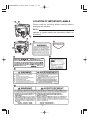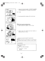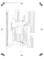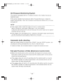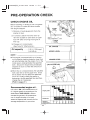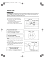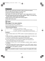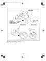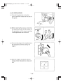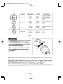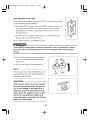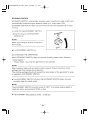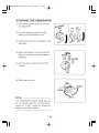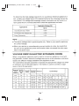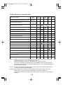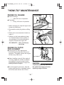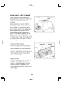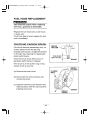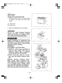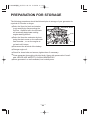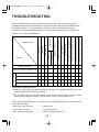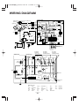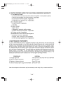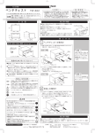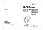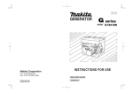
1
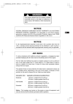
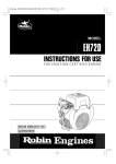
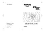
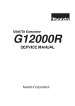
EF12000DE排対_GU1763 03.2.4 9:40 AM ページ001
Generator
OWNER'S MANUAL
EF12000DE
LIT-19626-01-05
7UX-28199-16
EF12000DE排対_GU1763 03.2.4 9:44 AM ページ01
EF12000DE排対_GU1763 03.2.4 9:44 AM ページ02
EF12000DE排対_GU1763 03.2.4 9:50 AM ページ03
EF12000DE排対_GU1763 03.2.4 9:50 AM ページ04
EF12000DE排対_GU1763 03.2.4 10:12 AM ページ05
ドキュメント3 03.2.4 11:46 AM ページ1
ドキュメント3 03.2.4 1:09 PM ページ1
-
1-
ドキュメント3 03.2.4 1:09 PM ページ2
-
2-
EF12000DE排対_GU1763 03.2.4 1:14 PM ページ3
1
LOCATION OF IMPORTANT LABELS
5
Please read the following labels carefully before
operating this machine.
NOTE :
Maintain or replace safety and insutruction labels, as
necessary.
4
6
1
2
2
3
4
3
膖膖膖膖膖膖膖膖膖膖膖
IMPORTANT ENGINE INFORMATION
EM
ENGINE FAMILY.
DISPLACEMENT 653 cm3
REFER TO OWNER'S MANUAL FOR MAINTENANCE SPECIFICATIONS AND
ADJUSTMENTS. THIS ENGINE MEETS EMISSION STANDARDS FOR
U.S. EPA REGULATIONS FOR SMALL NON-ROAD ENGINES (EMISSION
COMPLIANCE PERIOD OF 1000 HOURS) AND
CALIFORNIA SI SORE's.
YAMAHA MOTOR CO.,LTD.
EH63 .64 .65
膖膖膖膖
膖膖膖膖
5
6
-
3-
EF12000DE排対_GU1763 03.2.4 1:14 PM ページ4
-
4-
EF12000DE排対_GU1763 03.2.4 1:23 PM ページ5
-
5-
EF12000DE排対_GU1763 03.2.4 1:23 PM ページ6
-
6-
EF12000DE排対_GU1763 03.2.4 1:23 PM ページ7
-
7-
EF12000DE排対_GU1763 03.2.4 1:23 PM ページ8
-
8-
EF12000DE排対_GU1763 03.2.4 1:23 PM ページ9
-
9-
EF12000DE排対_GU1763 03.2.4 1:23 PM ページ10
-
10 -
EF12000DE排対_GU1763 03.2.4 1:29 PM ページ11
-
11 -
EF12000DE排対_GU1763 03.2.4 1:30 PM ページ12
1) Check fuel level at fuel level gauge.
2) If fuel level is low, refill with unleaded
automotive gasoline.
This engine is certified to operate on
automotive unleaded gasoline.
3) Be sure the fuel fillter screen is inserted.
-
12 -
EF12000DE排対_GU1763 03.2.4 1:30 PM ページ13
-
13 -
EF12000DE排対_GU1763 03.2.4 1:30 PM ページ14
-
14 -
EF12000DE排対_GU1763 03.2.4 1:30 PM ページ15
-
15 -
EF12000DE排対_GU1763 03.2.4 1:30 PM ページ16
-
16 -
EF12000DE排対_GU1763 03.2.4 1:38 PM ページ17
-
17 -
EF12000DE排対_GU1763 03.2.4 1:38 PM ページ18
-
18 -
EF12000DE排対_GU1763 03.2.4 1:38 PM ページ19
-
19 -
EF12000DE排対_GU1763 03.2.4 1:38 PM ページ20
-
20 -
EF12000DE排対_GU1763 03.2.4 1:38 PM ページ21
-
21 -
EF12000DE排対_GU1763 03.2.4 1:38 PM ページ22
-
22 -
EF12000DE排対_GU1763 03.2.4 1:38 PM ページ23
-
23 -
EF12000DE排対_GU1763 03.2.4 1:38 PM ページ24
-
24 -
EF12000DE排対_GU1763 03.2.4 1:38 PM ページ25
-
25 -
EF12000DE排対_GU1763 03.2.4 1:54 PM ページ26
Periodic Maintenance Schedule table
Every 8
hours
(Daily)
Maintenance Items
Clean generator and check bolts and nuts
Check and refill engine oil
Every
20
hours
Every
50
hours
Every
200
hours
Every
500
hours
Every
1000
hours
● (Daily)
● (Refill daily to
upper level)
Change engine oil (*Note 1)
●
(Initial)
● (Every 100 hours)
Replace engine oil filter (*Note 1)
●
(Initial)
●
Check battery electrolyte fluid level
●
Clean spark plug
●
Clean air cleaner
●
Replace air cleaner element
●
Clean fuel strainer
●
Clean and adjust spark plug and electrodes
●
Replace spark plug
●
● (Every 100 hours)
Spark arrester
Remove carbon from cylinder head (*Note 2)
●
Clean and adjust carburetor (*Note 2)
●
Clean engine base (oil pan) (*Note 2)
●
Check and adjust valve clearance (*Note 2)
●
Check and replace carbon brushes
●
●
(Yearly)
Replace fuel lines
Overhaul engine (*Note 2)
●
*Note 1 : Initial oil change should be performed after first twenty (20) hours of operation.
Thereafter change oil every hundred (100) hours.
Before changing oil, check for a suitable way to dispose of old oil.
Do not pour it down into sewage drains, onto garden soil or into open streams.
Your local zoning or environmental regulations will give you more detailed instructions on proper disposal.
*Note 2 : As to the procedures for these items, please refer to the SERVICE MANUAL or
consult your nearest Yamaha dealer.
*Note 3 : More frequent oil changing, oil filter replacement and air cleaner service on
replacement may be necessary depending on operating conditions.
This would include dusty environment, high ambient temperature, heavy engine
loading.
-
26 -
EF12000DE排対_GU1763 03.2.4 1:54 PM ページ27
"HOW-TO" MAINTENANCE
ENGINE OIL CHANGE
OIL DRAIN PLUG
(ON BOTH SIDE)
■
Initial oil change
・・・・・After 20 hours of operation
■
Thereafter
・・・・・Every 100 hours of operation
1. When changing oil, stop the engine and
loosen the drain plug.
2. Re-install the drain plug before refilling
oil.
OIL FILLER CAP
3. Refer to the recommended oil table on
page 11.
4. Always use the best grade and clean
oil. Contaminated oil, poor quality oil
and shortage of oil cause damage to
engine or shorten the engine life.
OIL CAPACITY : 1.55 L (1.36 lmp qt,
1.64 US qt)
ENGINE OIL FILTER
REPLACEMENT
■
Initial engine oil filter replacement
should be performed after 20 hours of
operation. Thereafter replace the engine
oil filter every 200 hours.
OIL FILTER
■
■
When installing a new oil filter, apply oil
to O-ring, attach the oil filter in position
and tighten 2/3 turns by hand or with
wrench after touching the O-ring to the
sealing surface of engine.
Run the engine for a minute ; stop the
engine and check for oil leakage around
the oil filter and recheck the oil level.
-
CAUTION :
To prevent injury, pay attention to
the spilled hot engine oil when
replacing engine oil filter.
27 -
EF12000DE排対_GU1763 03.2.4 1:59 PM ページ28
-
28 -
EF12000DE排対_GU1763 03.2.4 1:59 PM ページ29
-
29 -
EF12000DE排対_GU1763 03.2.4 1:59 PM ページ30
-
30 -
EF12000DE排対_GU1763 03.2.4 1:59 PM ページ31
-
31 -
EF12000DE排対_GU1763 03.2.4 1:54 PM ページ32
SPARK ARRESTER
SPARK ARRESTER
In a dry or wooded area, it is recommendable to use the engine with a spark arrester.
Some areas require the use of a spark arrester. Please check your local laws and
regulations before operating your engine.
The spark arrester must be cleaned regularly to keep it functioning as designed.
A clogged spark arrester :
Prevents the flow of exhaust gas
Reduces engine output
● Increases fuel consumption
● Makes starting difficult
●
●
If the engine has been running, the muffler and the spark arrester will be very hot.
Allow the muffler to cool before cleaning the spark arrester.
How to remove the spark arrester
1. Remove the flange bolts from the
muffler cover and remove the muffler
cover.
MUFFLER
2. Remove the special screw from the
spark arrester and remove the spark
arrester from the muffler.
SPARK
ARRESTER
SCREEN
SCREW
Clean the spark arrester screen
SPARK ARESSTER SCREEN
Use a brush to remove carbon deposits
from the spark arrester screen.
Be careful to avoid damaging the screen.
The spark arrester must be free of
breaks and holes. Replace the spark
arrester if it is damaged.
Install the spark arrester, and muffler
protector in the reverse order of
disassembly.
-
32 -
EF12000DE排対_GU1763 03.2.4 2:43 PM ページ33
PREPARATION FOR STORAGE
The following procedures should be followed prior to storage of your generator for
a period of 6 months or longer.
■
■
Drain fuel from fuel tank and strainer
(cup) carefully by disconnecting the
fuel line. Gasoline left in the fuel tank
will eventually deteriorate making
engine-starting difficult.
Screw for Drain
Drain fuel from the carburetor by loosening the drain screw on the carburetor
float chamber , or run the engine at
no-load until it stops.
■
Disconnect the terminal of the battery.
■
Change engine oil.
■
Check for loose bolts and screws, tighten them if necessary.
■
■
Clean generator thoroughly with oiled cloth. Spray with preservative if available. NEVER USE WATER TO CLEAN GENERATOR !
Store generator in a well ventilated, low humidity area.
-
33 -
EF12000DE排対_GU1763 03.2.4 2:17 PM ページ34
-
34 -
EF12000DE排対_GU1763 03.2.4 1:54 PM ページ35
TROUBLESHOOTING
Starter will not run
×
×
Rotation decreased
×
×
× × × × ×
Unstable rotation
×
×
× ×
Carbon brushes are excessively worn
Insufficient capacity of extension cable
× ×
×
× ×
Breaker turned off
Low power
Incorrect or poor connection of wires
Overload by connected appliance
Faulty spark plug
Low oil level
Clogging of Cooling air intake
× ×
×
Starter runs, but Engine will not start.
During operation
Clogging of Air cleaner
Problem
Leakage
Deteriorated fuel
Blown fuse
Low battery
Possible causes
Clogging
Fuel piping
When generator engine fails to start after several attempts, or if no electricity is
available at the output receptacles, check the possible causes in accordance with
the following table. If your generator still fails to start or generate electricity,
contact your nearest Yamaha dealer or authorized service center for further information or corrective procedures.
×
×
× ×
× × × × ×
The starter motor will not run :
■ Wait for more than 0.5 second after the engine is stopped and then turn the
starter switch to the "START" position.
■ If a remote control unit is connected, check if both starter switch on the control
panel and the engine switch on the remote control unit are switched on.
The engine stopped and the oil pressure warning lamp flashed for three minutes.
Check the following.
■ No fuel in the fuel tank ・
・・・・・・・・Supply fuel
■ Fuel cock not open
・・・・・・・・・・・Turn on fuel cock
■ No sufficient engine oil ・
・・・・・・・・Add or change engine oil
-
35 -
EF12000DE排対_GU1763 03.2.4 1:54 PM ページ36
SPECIFICATIONS
Model
EF12000DE
Type
Brush, Self-exciting, 2-pole, Single phase
Alternator
Rated frequency
60 Hz
Rated voltage
120V / 240V
Rated current
79.2 A / 39.6 A
Rated output
9500 VA
Maximum output
12000 VA
Power factor
1.0
Engine
Voltage regulator
A.V.R type
Model
EH65D
Type
Twin cylinder, Air-cooled, 4-stroke, Overhead valve engine
Displacement
653 cm3
Fuel
Automotive Unleaded Gasoline
Oil capacity
1.55 L (1.36 lmp qt, 1.64 US qt)
Starting system
Electric starter
Fuel tank capacity
Dimension
Rated continuous
operation per a
tankful of fuel
44 L (9.68 lmp gal, 11.62 US gal)
Rated
Approx. 8.2 hours
Large
826 mm (32.5 in)
Width
611 mm (24.1 in) [758 mm (29.8 in)]*1
High
771 mm (30.4 in) [856 mm (33.7 in)]*1
Dry weight
141 kg (310.8 lb) [149 kg (328.5 lb)]*2
Remote controller terminal
(Auto choke)
Valve clearance
(Intake & Exhaust)
Standard
0.0039 ± 0.0008 in (0.1 ± 0.02 mm)
Note : Adjust the valve clearance while the engine is cold.
Emissions durability period
(California only)
*1: [
*2: [
500 hours
] shows dimensions with castors.
] shows dry weight with castors installed.
-
36 -
EF12000DE排対_GU1763 03.2.4 1:54 PM ページ37
WIRING DIAGRAM
CONTROL BOX
Auto choke
(Bimetal)
R
LGrn
R
Blk/W
Blk
R/W
Fuel cut
Ignition coil
Blk/W
Blk
(AC output)
Idle
solenoid
W
W
(AVR)
1
5
W
W
Charge
coil
Exciting
coil
4 5 6
Electronic control unit
2 LBlu
3
4
Idle
control
unit
13 12 11 10 9 8 7
Org
Grn/Y
Y
LBlu
Org
R
R
Electric
starter
Brn
Org
Grn/Y
Org
Grn
Gry
Grn/Y
Grn/Y
Magnetic
switch
W
Oil pressure
warning lamp
(Red)
W
W
1 2 3
Economy
switch
Org
Y
Y
Blk
Blk
W
Grn
Gry
-M +M B L.IG ST
OFF
ON
START
Grn
Regulator
to earth
terminal
Blk15
R15
-
Gry
+
Key
switch
Blk
Oil pressure
switch
Battery 12V
Grn Org Blk
Grn/Y Gry
AC output
receptacle
(120V) REC1
AC output
receptacle
(120/240V) REC3
CONTROL BOX
Fuse
Connector
Remoto control
Blk
R
Idle
control
unit
Hr
V
W
LGrn
Brn
R
AC otuput
receptacle(120V)
REC2
W Blk Blk W
Brn LGrn LGrn Brn
Idle
control unit
Key
switch
W
No-fuse breaker
W
Auxiliary Winding
for Condenser
w
Blk
AC Winding 2
R
PL
Pilot lamp
Blu
Brush
AC output
receptacle
(120/240V) REC4
Grn/Y
w
Voltmeter
Field
Winding
Connector
(Remote control)
Blk
AC Winding 1
Blk
R
Grn/Y
GENERATOR
Brush
(AC 120V)
R
ST Relay
Engine
Exciting coil
AVR
Gr
Y
Y
n/Y
(4P)
Grn/Y
Grn/Y
Earth(Ground)
terminal
Wiring color cord
Blk
Blk/W
Blu
LBlu
Brn
:
:
:
:
:
Black
Black/White
Blue
Light blue
Brown
-
Brn/W
Grn
Grn/W
Org
Gry
:
:
:
:
:
37 -
Brown/White
Green
Green/White
Orange
Gray
R
W
Y
Pik
Grn/Y
:
:
:
:
:
Red
White
Yellow
Pink
Green/Yellow
Blk/R : Black/Red
R/W : Red/White
LGrn : Light green
EF12000DE排対_GU1763 03.2.4 1:54 PM ページ38
OPTIONAL PARTS
"HOW-TO" INSTALL THE WHEEL
(1) Checking of supplied accessories
(2) Tool preparation
■
Hoist or square bar (100 mm (3.94 in) by 100 mm (3.94 in), length : 700 mm (27.56 in))
■
Plier
■
Spanner or socket wrench (12 mm (0.472 in)), 2 units
(3) Installation procedures
(a) Raise the generator by about 100 mm (3.94 in), with hoist or with square bar put under
the bottom panel.
(b) Attach wheel mounting parts ① ,② ,stopper ⑨ , using clamp ⑩, ⑧ and wheel ③, to
wheel shaft ④.
Then check that wheel ③ is rotated smoothly. If moving turns out to be too complicated, assemble them together using grease. (4 locations / 2 pieces)
(c) Bend the tip of ① according to the shape of wheel shaft ④ as possible.
(d) Attach the assembled shaft to the foundation plate of the engine, using ⑤, ⑦, and ⑧.
(e) Attach the other shaft to the foundation plate of the generating unit, using ⑥ and ⑦.
(⑧ is not used.)
The tightening torque of bolts should be 20 to 25 Nm (2.0 to 2.5 kg-m).
WARNING
①
①
⑦
⑦
②
③
②
⑤
④
③
⑤
③
If you provide the generator with wheels,
always be sure to place the generator on
a level surface, locking the wheel with
the stopper and /or chocking the wheels.
⑥
⑦
①
⑧
⑩
④
⑨
①
⑥
⑦
②
⑧
③
REMOTE CONTROL UNIT
When the remote control unit is connected, the engine will not start unless both starter
switch on the control panel and the engine switch on the remote control unit are switched
on.
-
38 -
EF12000DE排対_GU1763 03.2.4 2:31 PM ページ39
-
39 -
EF12000DE排対_GU1763 03.2.4 2:31 PM ページ40
-
40 -
EF12000DE排対_GU1763 03.2.4 2:36 PM ページ41
-
41 -
EF12000DE排対_GU1763 03.2.4 2:36 PM ページ42
-
42 -
EF12000DE排対_GU1763 03.2.4 2:36 PM ページ43
-
43 -
EF12000DE排対_GU1763 03.2.4 2:36 PM ページ44
-
44 -
EF12000DE排対_GU1763 03.2.4 2:36 PM ページ45
3ZZ9020132
ISSUE EMD-GU1763
PRINTED IN JAPAN
2003.01-0.5x1