1
SR 4500
BEDIENUNGSANLEITUNG . . . . . . . . . . . . . S. 2
Bitte vor Inbetriebnahme des Gerätes lesen!
USER INSTRUCTIONS
. . . . . . . . . . . . . . . . .
Please read the manual before using the equipment!
MODE D’EMPLOI
. . . . . . . . . . . . . . . . . . . . . . . .
Veuillez lire cette notice avant d’utiliser le système!
ISTRUZIONI PER L’USO
. . . . . . . . . . . . . . .
Prima di utilizzare l’apparecchio, leggere il manuale!
MODO DE EMPLEO
. . . . . . . . . . . . . . . . . . . . .
¡Sirvase leer el manual antes de utilizar el equipo!
INSTRUÇÕES DE USO
. . . . . . . . . . . . . . . . .
Favor leia este manual antes de usar o equipamento!
p. 16
p. 30
p. 44
p. 58
p. 72
Table of Contents
Page
FCC Statement . . . . . . . . . . . . . . . . . . . . . . . . . . . . . . . . . . . . . . . . . . . . . . . . . . . . . . . . . . . . . . . . . . . . . . . 16
1
2
Safety and Environment . . . . . . . . . . . . . . . . . . . . . . . . . . . . . . . . . . . . . . . . . . . . . . . . . . . . . . . . . . . . 17
1.1 Safety . . . . . . . . . . . . . . . . . . . . . . . . . . . . . . . . . . . . . . . . . . . . . . . . . . . . . . . . . . . . . . . . . . . . . . . 17
1.2 Environment . . . . . . . . . . . . . . . . . . . . . . . . . . . . . . . . . . . . . . . . . . . . . . . . . . . . . . . . . . . . . . . . . . 17
Description . . . . . . . . . . . . . . . . . . . . . . . . . . . . . . . . . . . . . . . . . . . . . . . . . . . . . . . . . . . . . . . . . . . . . . 18
2.1 Introduction . . . . . . . . . . . . . . . . . . . . . . . . . . . . . . . . . . . . . . . . . . . . . . . . . . . . . . . . . . . . . . . . . . . 18
2.2 Packing List. . . . . . . . . . . . . . . . . . . . . . . . . . . . . . . . . . . . . . . . . . . . . . . . . . . . . . . . . . . . . . . . . . . 18
2.3 Optional Accessories . . . . . . . . . . . . . . . . . . . . . . . . . . . . . . . . . . . . . . . . . . . . . . . . . . . . . . . . . . . . 18
2.4 General Description . . . . . . . . . . . . . . . . . . . . . . . . . . . . . . . . . . . . . . . . . . . . . . . . . . . . . . . . . . . . . 18
2.5 Controls. . . . . . . . . . . . . . . . . . . . . . . . . . . . . . . . . . . . . . . . . . . . . . . . . . . . . . . . . . . . . . . . . . . . . . 18
2.5.1 Front Panel . . . . . . . . . . . . . . . . . . . . . . . . . . . . . . . . . . . . . . . . . . . . . . . . . . . . . . . . . . . . . . . 18
2.5.2 Rear Panel . . . . . . . . . . . . . . . . . . . . . . . . . . . . . . . . . . . . . . . . . . . . . . . . . . . . . . . . . . . . . . . 19
2.6 Audio Outputs . . . . . . . . . . . . . . . . . . . . . . . . . . . . . . . . . . . . . . . . . . . . . . . . . . . . . . . . . . . . . . . . . 19
2.7 Bottom Panel . . . . . . . . . . . . . . . . . . . . . . . . . . . . . . . . . . . . . . . . . . . . . . . . . . . . . . . . . . . . . . . . . . 19
3
Setting Up . . . . . . . . . . . . . . . . . . . . . . . . . . . . . . . . . . . . . . . . . . . . . . . . . . . . . . . . . . . . . . . . . . . . . . . 20
3.1 Placing the Receiver. . . . . . . . . . . . . . . . . . . . . . . . . . . . . . . . . . . . . . . . . . . . . . . . . . . . . . . . . . . . . 20
3.2 Rack Mounting a Single Receiver . . . . . . . . . . . . . . . . . . . . . . . . . . . . . . . . . . . . . . . . . . . . . . . . . . . 20
3.3 Rack Mounting Two Receivers Side by Side . . . . . . . . . . . . . . . . . . . . . . . . . . . . . . . . . . . . . . . . . . . . 20
3.4 Connecting the Receiver to a Mixer . . . . . . . . . . . . . . . . . . . . . . . . . . . . . . . . . . . . . . . . . . . . . . . . . . 20
3.5 Connecting the Receiver to Power . . . . . . . . . . . . . . . . . . . . . . . . . . . . . . . . . . . . . . . . . . . . . . . . . . . 20
3.6 Powering Up/Powering Down . . . . . . . . . . . . . . . . . . . . . . . . . . . . . . . . . . . . . . . . . . . . . . . . . . . . . . 20
3.7 LOCK Mode . . . . . . . . . . . . . . . . . . . . . . . . . . . . . . . . . . . . . . . . . . . . . . . . . . . . . . . . . . . . . . . . . . . 21
3.8 Setting Up the Receiver (ACTIVE mode) . . . . . . . . . . . . . . . . . . . . . . . . . . . . . . . . . . . . . . . . . . . . . . . 21
3.8.1 Automatic Frequency Selection . . . . . . . . . . . . . . . . . . . . . . . . . . . . . . . . . . . . . . . . . . . . . . . . 21
3.8.2 Automatic Frequency Selection for Multichannel Systems . . . . . . . . . . . . . . . . . . . . . . . . . . . . . 22
3.8.3 Manual Frequency Selection: Preset Channel . . . . . . . . . . . . . . . . . . . . . . . . . . . . . . . . . . . . . . 22
3.8.4 Manual Frequency Selection: Direct . . . . . . . . . . . . . . . . . . . . . . . . . . . . . . . . . . . . . . . . . . . . . 22
3.8.5 Editing the Receiver Name . . . . . . . . . . . . . . . . . . . . . . . . . . . . . . . . . . . . . . . . . . . . . . . . . . . . 22
3.8.6 Finding Interference Frequencies . . . . . . . . . . . . . . . . . . . . . . . . . . . . . . . . . . . . . . . . . . . . . . . 23
3.9 Before the Soundcheck . . . . . . . . . . . . . . . . . . . . . . . . . . . . . . . . . . . . . . . . . . . . . . . . . . . . . . . . . . 23
3.9.1 Rehearsal Function . . . . . . . . . . . . . . . . . . . . . . . . . . . . . . . . . . . . . . . . . . . . . . . . . . . . . . . . . 24
3.9.2 Setting the Squelch Threshold . . . . . . . . . . . . . . . . . . . . . . . . . . . . . . . . . . . . . . . . . . . . . . . . . 24
3.10 Multichannel Systems . . . . . . . . . . . . . . . . . . . . . . . . . . . . . . . . . . . . . . . . . . . . . . . . . . . . . . . . . . . 25
4
Extra Functions . . . . . . . . . . . . . . . . . . . . . . . . . . . . . . . . . . . . . . . . . . . . . . . . . . . . . . . . . . . . . . . . . . . 26
4.1 Introduction . . . . . . . . . . . . . . . . . . . . . . . . . . . . . . . . . . . . . . . . . . . . . . . . . . . . . . . . . . . . . . . . . . . 26
4.2 NAME . . . . . . . . . . . . . . . . . . . . . . . . . . . . . . . . . . . . . . . . . . . . . . . . . . . . . . . . . . . . . . . . . . . . . . . 26
4.3 STATUS . . . . . . . . . . . . . . . . . . . . . . . . . . . . . . . . . . . . . . . . . . . . . . . . . . . . . . . . . . . . . . . . . . . . . . 26
4.4 THRESH. . . . . . . . . . . . . . . . . . . . . . . . . . . . . . . . . . . . . . . . . . . . . . . . . . . . . . . . . . . . . . . . . . . . . . 26
4.5 INFO . . . . . . . . . . . . . . . . . . . . . . . . . . . . . . . . . . . . . . . . . . . . . . . . . . . . . . . . . . . . . . . . . . . . . . . . 27
4.6 LIGHT . . . . . . . . . . . . . . . . . . . . . . . . . . . . . . . . . . . . . . . . . . . . . . . . . . . . . . . . . . . . . . . . . . . . . . . 27
4.7 RESET . . . . . . . . . . . . . . . . . . . . . . . . . . . . . . . . . . . . . . . . . . . . . . . . . . . . . . . . . . . . . . . . . . . . . . . 27
4.8 Transmitter Status Indications . . . . . . . . . . . . . . . . . . . . . . . . . . . . . . . . . . . . . . . . . . . . . . . . . . . . . . 27
5
Cleaning. . . . . . . . . . . . . . . . . . . . . . . . . . . . . . . . . . . . . . . . . . . . . . . . . . . . . . . . . . . . . . . . . . . . . . . . . 27
6
Troubleshooting . . . . . . . . . . . . . . . . . . . . . . . . . . . . . . . . . . . . . . . . . . . . . . . . . . . . . . . . . . . . . . . . . . . 28
7
Specifications . . . . . . . . . . . . . . . . . . . . . . . . . . . . . . . . . . . . . . . . . . . . . . . . . . . . . . . . . . . . . . . . . . . . 29
FCC Statement
This equipment has been tested and found to comply with the limits for a Class B digital device, pursuant to Part15 of the FCC Rules.
These limits are designed to provide reasonable protection against harmful interference in a residential installation. This equipment generates, uses, and can radiate radio frequency energy and, if not installed and used in accordance with the instructions, may cause
harmful interference to radio communications. However, there is no guarantee that interference will not occur in a particular installation.
If this equipment does cause harmful interference to radio or television reception, which can be determined by turning the equipment
off and on, the user is encouraged to try to correct the interference by one or more of the following measures:
•
•
•
•
Reorient or relocate the receiving antenna.
Increase the separation between the equipment and the receiver.
Connect the equipment into an outlet on a circuit different from that to which the receiver is connected.
Consult the dealer or an experienced radio/TV technician for help.
Shielded cables and I/O cords must be used for this equipment to comply with the relevant FCC regulations.
Changes or modifications not expressly approved in writing by AKG Acoustics may void the user’s authority to operate this equipment.
This device complies with Part 15 of the FCC Rules. Operation is subject to the following two conditions: (1) this device may not cause
harmful interference, and (2) this device must accept any interference received, including interference that may cause undesired operation.
16
SR 4500
1 Safety and Environment
!
L
1. Do not spill any liquids on the equipment and do not drop any objects through the ventilation slots in the equipment.
2. The equipment may be used in dry rooms only.
3. The equipment may be opened, serviced, and repaired by authorized personnel only. The equipment contains no userserviceable parts.
4. Before connecting the equipment to power, check that the AC mains voltage stated on the optional power supply is
identical to the AC mains voltage available where you will use the equipment.
5. Operate the equipment with an optional power supply with an output voltage of 12 VDC only. Using power supplies
with an AC output and/or a different output voltage may cause serious damage to the unit.
6. If any solid object or liquid penetrates into the equipment, shut down the sound system immediately. Disconnect the
power supply from the power outlet immediately and have the equipment checked by AKG service personnel.
7. If you will not use the equipment for a long period of time, disconnect the power supply from the power outlet.
Please note that the equipment will not be fully isolated from power when you set the power switch to OFF.
8. Do not place the equipment near heat sources such as radiators, heating ducts, or amplifiers, etc. and do not expose it to direct sunlight, excessive dust, moisture, rain, mechanical vibrations, or shock.
9. To avoid hum or interference, route all audio lines, particularly those connected to the microphone inputs, away
from power lines of any type. If you use cable ducts, be sure to use separate ducts for the audio lines.
10.Clean the equipment with a moistened (not wet) cloth only. Be sure to disconnect the power supply from the power
outlet before cleaning the equipment! Never use caustic or scouring cleaners or cleaning agents containing alcohol or solvents since these may damage the enamel and plastic parts.
11.Use the equipment for the applications described in this manual only. AKG cannot accept any liability for damages
resulting from improper handling or misuse.
1.1 Safety
1. The power supply will draw a small amount of current even when the equipment is switched off. To save energy,
disconnect the power supply from the power outlet if you will leave the equipment unused for a long period of time.
2. When scrapping the equipment, separate the case, circuit boards, and cables, and dispose of all components in accordance with local waste disposal rules.
3. The packaging of the equipment is recyclable. Dispose of the packaging in an appropriate container provided by the
local waste collection/recycling entity and observe all local legislation relating to waste disposal and recycling.
1.2 Environment
SR 4500
17
2 Description
2.1 Introduction
Thank you for purchasing an AKG product. This Manual contains important instructions for setting up and operating your
equipment. Please take a few minutes to read the instructions below carefully before operating the equipment.
Please keep the Manual for future reference. Have fun and impress your audience!
2.2 Packing List
1 SR 4500 receiver
2 UHF antennas
1 19” rack mounting kit
• Check that the packaging contains all of the components listed above. Should any item be missing, please contact
your AKG dealer.
2.3 Optional Accessories
• For optional accessories, refer to the current AKG catalog or folder, or visit www.akg.com. Your dealer will be glad
to help.
2.4 General Description
The SR 4500 is a stationary True Diversity receiver for use with all WMS 4000 transmitters. The SR 4500 operates in
a subband up to 30 MHz wide of the 500 MHz to 862 MHz UHF carrier frequency band. Within the subband, you can
either set the carrier frequency directly in 25-kHz increments or select one of the channels of the Preset Frequency
Groups of your receiver.
A backlit display indicates all important parameters including the receiving frequency, audio level, RF level, current operating mode, and remaining transmitter battery life.
The receiver provides two operating modes:
• In LOCK mode, all setup functions are electronically locked to prevent parameters from being readjusted unintentionally during a performance or lecture. The "LOCK" label on the display indicates the receiver is in LOCK mode.
• ACTIVE mode allows you to adjust and save all receiver parameters. In ACTIVE mode, the "LOCK" label disappears.
The receiver provides both a balanced XLR and an unbalanced 1/4" audio output.
You can use the receiver as a standalone unit or install it in a 19" rack using the supplied rack mounting kit.
2.5 Controls
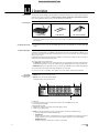
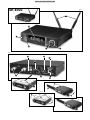
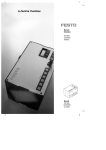
2.5.1 Front Panel
Refer to fig. 1.
1 ON/OFF: Switches power to the unit on or off.
2 Display: The receiver provides a backlit display:
The display indicates all receiver parameters:
a
c
e
d
f
a
b
c
d
e
f
Audio level
Preset/Receiver Name, Frequency Group, Channel (shown in Preset and NAME screens only)
Received signal field strength
Diversity indicators (A/B)
Alphanumeric display of current setting or transmitter battery capacity
Parameter to be adjusted, mode
3 SETUP: Sets the various parameters of the receiver. The SETUP control has the following functions:
• Long push: Toggle between LOCK and ACTIVE modes.
• In LOCK mode:
- Turn all the way CW or CCW to scroll through the Preset screen (only available if a Preset has been stored preciously), Frequency screen, receiver name, battery status (battery capacity in hours), and Gain displays.
• In ACTIVE mode only:
- Short push: Call up the selected menu or confirms a selected value.
18
SR 4500
2 Description
- Turn all the way CW to select a menu item or increase a parameter value.
- Turn all the way CCW to select a menu item or decrease a parameter value.
4 Sticker: Indicates the receiver frequency version.
5 LED ring (green/red): If one or more warning functions are activated (see section 4.3), the LED ring will be lit red
when a critical condition occurs. As long as all parameters are within their normal ranges, the LED ring is lit green.
6 DC ONLY: Locking DC input for connecting an optional power supply.
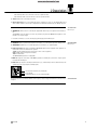
2.5.2 Rear Panel
Refer to fig. 2.
7 ANTENNA A/B: 2 BNC sockets for connecting the supplied UHF antennas (7a) or an optional remote antenna system.
The ANTENNA sockets also allow the receiver to be powered by an optional PS 4000 W antenna splitter as an alternative to a local power supply.
• For details on antennas, accessories, and frequency planning support visit www.akg.com.
8 BALANCED: Balanced 3-pin XLR audio output for connecting to, e.g., a microphone input on the mixing console.
2.6 Audio Outputs
Refer to fig. 2.
9 UNBALANCED: Unbalanced 1/4" TS audio output jack for connecting to, e.g., a guitar amplifier.
10 Output level switch: Slide switch for matching the BALANCED output level to the input gain of the equipment connected to the receiver. The switch has three positions:
-30 dB: for high-sensitivity microphone level inputs on mixers or other equipment,
0 dB: standard setting for microphone level inputs,
+6 dB: for studio mixers.
The UNBALANCED output level is not adjustable.
11 DATA: Data output for connecting to a HUB 4000 Q (optional) for controlling the receiver from a computer system.
For details visit www.akg.com.
12 LOGIC OUT: Logic output for controlling external functions (e.g., channel muting on an AS 8 automatic mixer). This
3-pin Phoenix connector provides the following signals:
� � �
1 Receiver audio output on (5 V) / muted (0 V)
2 Logic ground
3 Transmitter batteries o.k. (5 V) / nearly dead (0 V)
The receiver type plate (13) indicating available carrier frequency ranges and approval information is affixed to the bottom panel.
SR 4500
2.7 Bottom Panel
19
3 Setting Up
!
L
Important!
• Prior to setting up the receiver, check that the AC mains voltage stated on your power supply is identical
to the AC mains voltage available where you will use your system. Using the power supply with a different AC voltage may cause damage to the unit.
Note:
• In the the following sections, flashing characters are identified by angle symbols ">" and "<". All numerical values
shown are examples of possible settings.
3.1 Placing the Receiver
Reflections off metal parts, walls, ceilings, etc. or the shadow effects of musicians and other people may weaken or cancel the direct transmitter signal.
For best results, place the receiver or remote antennas as follows:
1. Place the receiver/antennas near the performance area (stage). Make sure, though, that the transmitter will never
get any closer to the receiver than 10 ft (3 m). Optimum separation is 16 ft. (5 m).
2. Check that you can see the receiver from where you will be using the transmitter. Shadow effects caused by people or objects may disrupt the radio link.
3. Place the receiver at least 5 ft. (1.5 m) away from any big metal objects, walls, scaffolding, ceilings, etc.
Note:
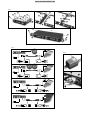
3.2 Rack Mounting
a Single Receiver
Refer to fig. 3.
1. Unscrew the four rubber feet (1) from the receiver bottom panel.
2. Unscrew the two fixing screws (2) from each side panel.
3. Use the fixing screws (2) to screw the short bracket (3) to one side panel and the long bracket (4) to the other side
panel. The brackets are contained in the supplied rack mounting kit.
4. Install the receiver in your rack.
3.3 Rack Mounting
Two Receivers Side by Side
Refer to fig. 4.
1. Unscrew the four rubber feet (1) from each receiver's bottom panel and remove the screws (5) from the rubber feet
(1).
2. Unscrew the two fixing screws (2) from the right-hand side panel of one receiver and from the left-hand side panel
of the other receiver.
3. Remove the plastic covers (3) from the side panels with the fixing screws (2) still on.
4. Insert one connecting strip (4) into each free slot in the side panel of the first receiver, making sure to align the hole
in each connecting strip (4) with the appropriate threaded hole in the receiver bottom panel.
5. Fix the three connecting strips (4) on the first receiver using three of the screws (5) you removed from the rubber feet.
6. To join the two receivers, slide the connecting strips (4) on the first receiver through the free slots in the side panel
of the second receiver. Make sure to align the hole in each connecting strip (4) with the appropriate threaded hole
in the bottom panel of the second receiver.
7. Fix the connecting strips (4) on the second receiver using the three screws (5) you removed from the rubber feet.
8. Screw a short bracket (6) to the outer side panel of each receiver using for each bracket two of the screws (2) you
removed from the receiver side panels.
9. Install the receivers in your rack.
Note:
20
• You can either use the receiver freestanding or mount it in a 19" rack using the supplied rack mounting kit.
• Be sure to keep the remaining screws (5) for later use.
3.4 Connecting the Receiver
to a Mixer
Refer to figs. 2 and 5.
•
-
3.5 Connecting the Receiver
to Power
Refer to fig. 6.
1. Check that the AC mains voltage stated on your power supply is identical to the AC mains voltage available where you will use your system. Using the power supply with a different AC voltage may cause damage to the unit.
2. Plug the feeder cable (1) on your power supply into the DC ONLY socket (2) on the receiver rear panel and screw
down the DC connector (3).
3. Plug the power cable on the power supply into a convenient power outlet.
3.6 Powering Up/Powering Down
1. Press the front panel ON/OFF switch to switch power to the receiver ON.
The display will indicate the currently active frequency.
If power to the transmitter is OFF or the RF level at the antennas is zero for some other reason (e.g., shadow effects), the "MUTE" label will appear on the display and the audio output will be muted.
If the antennas receive RF signal, the bargraph meters below "A" and "B" indicate the field strength of the signal
received by the active antenna.
The bargraph below "AUDIO" indicates the audio level. "CLIP" illuminates to indicate audio signal clipping.
2. After approximately 5 seconds, the display will change to the last active status screen (before powering down) and
the "LOCK" label. The receiver is now in LOCK mode.
3. To power down, press and hold ON/OFF until the display goes dark.
Connect the audio output to the desired input:
BALANCED socket (8) - XLR cable - microphone input: set output level switch (10) to "-30 dB".
BALANCED socket (8) - XLR cable - line input: set output level switch (10) to "0 dB" or "+6 dB".
UNBALANCED jack (9) - 1/4" jack cable - unbalanced 1/4" microphone or line input jack.
SR 4500
3 Setting Up
In LOCK mode, the receiver receives the transmitter signal. The receiver is electronically locked so you cannot make
any adjustments. You may, however, call up the various status screens one after the other. The "LOCK" label is shown
on the display.
To scroll through the following status screens, turn the SETUP control CW or CCW:
3.7 LOCK Mode
• Preset (comes up only if a Preset has been saved): Carrier frequency shown as channel number within a Frequency
Group
• Frequency: Carrier frequency in MHz. (This screen is always available, even if no Preset has been saved.)
• Name: Current receiver name (comes up only if you have previously named the receiver)
• Battery: Transmitter battery capacity in hours. (This screen will not be saved on powering down.) The way the capacity is indicated depends on the remaining battery life:
If no battery information is received or the information is invalid, the following message appears on the display:
"BAT--h".
• "GAIN": Current transmitter gain setting.
When power to the transmitter is off, the display will indicate "GAIN--". If you switch the transmitter off while the
receiver is on, "GAIN--" will alternate with "TX OFF".
1. To enter ACTIVE mode, press and hold the SETUP control until the "LOCK" label disappears.
2. Turn the SETUP control CW or CCW to select the desired setup menu. The following setup menus are available:
3.8 Setting Up the Receiver
(ACTIVE Mode)
Selecting parameters
- PRESET: "FREQ / NAME / GROUP / CHANNEL", e.g., "FREQ / SD 3.0 01"
- Frequency: "FREQ XXX.XXX", e.g., "FREQ / 720.000"
- Receiver name, e.g., "NAME / GUITAR"
- "SCAN": Environment Scan
- "SQL": Squelch Threshold
- "RHSL": Rehearsal
- "X-TRA": Extra functions
3. Press the SETUP control briefly to select the desired setup menu. The name of the selected menu, the selected menu
item, and the parameter to be adjusted will start flashing.
4. Turn the SETUP control CW or CCW to select the desired setting.
5. Press the SETUP control as many times as needed to call up the message "SAVE -- >Y<".
a) To save your setting, press the SETUP control briefly. The display will revert to the selected setup menu.
b) If you'd rather not save your setting, turn the SETUP control CW or CCW. The display will change to
"SAVE -- >N<".
- Press the SETUP control briefly. The display will revert to the selected setup menu.
Saving selected settings
6. To return to LOCK mode, press and hold the SETUP control until the "LOCK" label appears on the display.
Returning to LOCK mode
1.
2.
3.
4.
5.
6.
3.8.1 Automatic
Frequency Selection
Select "FREQ" -> "GROUP" -> "AUTO".
Press the SETUP control briefly. The display will change to "NoCH >1<".
Select the number of channels you need.
Press the SETUP control briefly. The display will change to ">NAME<" / ">SD<".
Turn the SETUP control CW to select the next Preset. The Preset names are arranged in alphabetical order.
Press the SETUP control briefly. The receiver will automatically find a Group with the selected number of clean frequencies within the selected Preset and tune to the first clean frequency.
• Clean frequencies are frequencies where the receiver finds no RF signal or an RF signal whose level is lower than
the current threshold setting. (Refer to section 4.4.)
Note:
7. As soon as the receiver has found a clean frequency, the channel number assigned to this frequency (e.g.,
">SD 3.0 01<") will be displayed.
8. Press the SETUP control briefly.
Select "SAVE -- >Y<" to save your new setting or "SAVE -- >N<" to reject the change.
The display will revert to the "FREQ / GROUP / AUTO" menu.
If the receiver has found no clean frequency, the display will indicate ">SD -- -- <".
• Press the SETUP control briefly. The display will change to ">RETRY<".
• To try again, press the SETUP control briefly and repeat steps 3 through 6 above.
• If you prefer not to start a new frequency search, select ">EXIT<" and press the SETUP control briefly. The change
will not be saved and the display will revert to the "FREQ / GROUP / AUTO" menu.
SR 4500
Note:
21
3 Setting Up
3.8.2 Automatic Frequency
Selection for Multichannel Systems
1. Select the frequency on the first receiver (refer to section 3.8.1 above).
2. Switch ON any radio microphones, personal monitor transmitters, etc. (including even those made by other
manufacturers)! This is the only way to make sure the receiver will find frequencies that will be free of any
mutual interference during the performance.
3. Tune the transmitter assigned to the first receiver to the same frequency that you selected on the receiver and
switch power to the transmitter on.
4. On each of the other receivers, select "FREQ -> CHANNEL -> AUTO".
5. Press the SETUP control briefly. The display will change to ">SD 3.0 -- <".
6. Select the same Preset (">NAME<") and the same Group (">GROUP<") as you selected on the first receiver.
7. Press the SETUP control briefly. The receiver will automatically search for the nearest clean frequency.
Note:
• Clean frequencies are frequencies where the receiver finds no RF signal or an RF signal whose level is lower than
the current threshold setting. (Refer to section 4.4.)
8. As soon as the receiver has found a clean frequency, the channel number assigned to this frequency (e.g.,
">SD 3.0 01<") will be displayed.
9. Press the SETUP control briefly.
Select "SAVE -- >Y<" to save your new setting or "SAVE -- >N<" to reject the change.
The display will revert to the Preset menu.
Note:
If the receiver has found no clean frequency, the display will indicate ">SD -- -- <".
• Press the SETUP control briefly. The display will change to ">RETRY<".
• To try again, press the SETUP control briefly and repeat steps 3 through 7 above. You may have to select a different Group ON ALL RECEIVERS.
• If you prefer not to start a new frequency search, select ">EXIT<" and press the SETUP control briefly. The change
will not be saved and the display will revert to the Preset menu.
3.8.3 Manual Frequency Selection:
Preset Channel
1. Select the Preset menu (“FREQ / NAME / GROUP / CHANNEL”).
The display will show the currently active channel.
If you have set the current receiving frequency in the Frequency menu or no Preset has been saved yet, the following menu will appear in the display: "FREQ / -- -- -- -- -- --".
2. Press the SETUP control briefly. The display will change to "FREQ / >NAME< / >SD<".
3. Select the desired Preset, the desired frequency ">GROUP<", and the desired ">CHANNEL<" (i.e., frequency)
within the selected Group.
4. Press the SETUP control briefly.
Select "SAVE -- >Y<" to save your new setting or "SAVE -- >N<" to reject the change.
The display will revert to the Preset menu.
3.8.4 Manual Frequency Selection:
Direct
1.
2.
3.
4.
Note:
• If a Preset channel had been active before you selected a frequency directly, the display will revert to the Preset menu
if you reject your changes.
3.8.5 Editing the Receiver Name
This menu lets you edit the current name of the receiver. If you have not named the receiver yet or deleted its previous
name, this menu will not be available. The "X-TRA" menu, however, allows you to save a new name at any time (refer
to section 4.2).
1.
2.
3.
4.
5.
6.
Note:
22
Select the Frequency menu (“FREQ XXX.XXX”).
Press the SETUP control briefly. The display will change to "FREQ / >720.000<”.
Select the desired frequency.
Press the SETUP control briefly.
Select "SAVE -- >Y<" to save your new setting or "SAVE -- >N<" to reject the change.
The display will revert to the Frequency menu.
Select the "NAME" menu.
Press the SETUP control briefly. The first character will start flashing.
To change the first character turn the SETUP control CW or CCW.
Press the SETUP control briefly. The second character will start flashing:
Repeat the two steps above to change all characters as desired.
Press the SETUP control briefly.
Select "SAVE -- >Y<" to save your new setting or "SAVE -- >N<" to reject the change.
The display will revert to the “NAME” menu.
• The “>DELETE<” option lets you delete the receiver name currently in memory.
Pressing the SETUP contgrol briefly will bring up the “X-TRA / EXTRA” menu. You can now enter a new name: Select “>NAME<” and repeat steps 2 through 6 above.
SR 4500
3 Setting Up
The Environment Scan function automatically searches the receiver's entire frequency band from Start to Stop (see Manual Supplement) for interference frequencies. During the search, the audio output is muted and the display indicates
the frequencies in MHz as they are scanned.
The frequency spacing for the automatic scan is 100 kHz. Frequencies whose field strength exceeds the factory-set
threshold (or the threshold you may have set using the Threshold function in the “X-TRA” menu) are defined as interference frequencies and saved in a scan list. Once the scan is completed, you can scroll through the scan list.
The receiver can store a maximum of eight interference frequencies. As soon as the Stop frequency is reached or the
scan list is full, the scan will be stopped automatically.
3.8.6 Finding
Interference Frequencies
Venues that are extremely hostile to RF transmission may make it necessary to change the Environment Scan threshold setting. You can change the setting using the ">THRESH<" function in the "X-TRA" menu.
Note:
1. Select "SCAN" -> "ENVIRO".
2. Press the SETUP control briefly. The display will change to ">START<".
3. a) To start the scan, press the SETUP control briefly. The scan will start and the display will show the frequencies as
they are scanned.
b) To exit Environment Scan, turn the SETUP control CW or CCW. The ">EXIT<" option will appear on the display
and start flashing.
4. Once the scan has reached the Stop frequency, the scan is automatically stopped and the message "READY" appears on the display.
5. To view the first item on the scan list, press the SETUP control briefly*. To scroll through the other items, turn the
SETUP control CW or CCW.
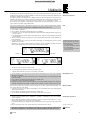
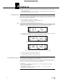
An interference source can be a single frequency as in example 1 or a frequency band as in example 2 below. The
RF meter on the display indicates the noise level of the scanned frequency or band.
* If Environment Scan has found no interference frequencies, the message
"CLEAN" will appear on the display.
• Press SETUP briefly.
• Turn SETUP CW to bring up "EXIT".
• Press SETUP briefly.
The receiver will return to the Environment Scan menu.
Example 1: A noise level of -90 dB has been found on the receiving frequency of 762 MHz.
Example 2: A max. noise level of -80 dB has been found in the 764 MHz to 767 MHz band.
The last item on the scan list is the "EXIT" option.
6. To scroll through the list again, turn the SETUP control CW or CCW.
To return to the Environment Scan menu, press the SETUP control briefly.
• You can interrupt the scan at any time by pressing the SETUP control briefly. If you do, the message "PAUSED"
will appear on the display.
• To view the scan list, press the SETUP control briefly. You can scroll through the items on the list by turning the SETUP
control CW or CCW.
• Press the SETUP control briefly. The display will offer the "CONT" option.
• To resume the scan, press the SETUP control briefly.
• If Environment Scan has found no interference frequencies, the message "CLEAN" will appear on the display. Turn
the SETUP control CW and select "CONT" to continue the scan or "EXIT" to return to the Environment Scan menu.
Interrupting the scan:
If the scan list is full before the Stop frequency has been reached, the scan will be stopped automatically and the message "OVFL" will appear on the display.
• To view the the scan list, press the SETUP control briefly. You can scroll through the items on the list by turning the
SETUP control CW or CCW.
• Press the SETUP control briefly. The display will offer the "CONT" option.
• Press the SETUP control briefly again. The scan list will be erased and the scan resumed.
Memory overflow:
1. Activate the Rehearsal function ("RHSL / REHEAR -> >START< -> RECORD") on the receiver referring to
section 3.9.1 below.
2. Move the transmitter around the area where you will use the system to check the area for "dead spots", i.e., places
where the field strength seems to drop and reception deteriorates.
If you find any dead spots, try to eliminate them by repositioning the receiver. If this does not help, avoid the dead
spots.
3. If the received signal is noisy, set the squelch threshold to a level where the noise will stop.
3.9 Before the Soundcheck
• Never set the squelch threshold any higher than absolutely necessary. The higher the squelch threshold,
the lower the sensitivity of the receiver and thus the usable range between transmitter and receiver.
SR 4500
See also section 3.9.2.
!
L
Important!
23
3 Setting Up
4. The RF meter on the receiver extinguishing and the "MUTE" message appearing mean that no signal is being received or the squelch is active.
Switch the transmitter ON, move closer to the receiver, or set the squelch threshold to the point that the "MUTE"
message will disappear and the RF meter come on again.
3.9.1 Rehearsal Function
The Rehearsal function detects a maximum of six dropouts and records the time each dropout occurred, the minimum
field strength at each antenna, the field strength ratio between the two antennas as a percentage, and the maximum
audio level. The recording will stop automatically after 15 minutes (or when the Rehearsal memory is full). You can view
the list of results after the recording has stopped.
1. Select "RHSL /REHEAR -> >START<* -> RECORD".
* If you do not wish to start Rehearsal turn the SETUP control CW or CCW.
Select "EXIT" to return to the Rehearsal menu.
Note:
• You can stop the test at any time by briefly pressing the SETUP control.
2. When the test is completed, the first result (Example 1 below) or "OVFL" will appear on the display.
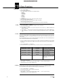
Example 1: Dropout after 12 seconds, maximum audio level: -6 dB.
3. To scroll through the result list, turn the SETUP control CW or CCW. The first six of a total of eight memory locations
are assigned to dropouts, the last two for reception statistics (Examples 2 and 3 below).
Example 2: Antenna A was active for 55% of the test period.
Maximum audio level: -6 dB; minimum field strength at antenna A: -90 dB.
Example 3: Antenna B was active for 45% of the test period.
Maximum audio level: -6 dB; minimum field strength at antenna B: less than -100 dB.
The last item on the result list is followed by the "EXIT" option.
4. To scroll through the list again, turn the SETUP control CCW.
To return to the Rehearsal menu press the SETUP control briefly.
3.9.2 Setting the Squelch Threshold
The adjustable squelch will mute the receiver if the received signal is too weak so the related noise or the self-noise of
the receiver will not become audible while the transmitter is off the air.
The squelch threshold settings available include ”TCSQ” (automatic Tone Code Squelch) and several preset values.
In TCSQ mode, the squelch threshold remains permanently set to -100 dBm. The transmitter signal contains a continuous pilot tone. If the pilot tone stops, the receiver's audio output will be muted.
1.
2.
3.
4.
24
Select "SQL".
Press the SETUP control briefly. The current setting, e.g., ">-90 dB<", will be flashing on the display.
Select the desired squelch threshold.
Press the SETUP control briefly.
Select "SAVE -- >Y<" to save your new setting or "SAVE -- >N<" to reject the change.
The display will revert to the Squelch menu.
SR 4500
3 Setting Up
1. Be sure to assign a separate carrier frequency to each wireless channel (transmitter and receiver).
2. To find intermodulation-free carrier frequencies quickly and easily, we recommend using Automatic Frequency Selection (see sections 3.8.1 and 3.8.2) to select all required frequencies from the same Frequency Group within the
same Preset.
3. Do not operate two or more wireless channels on the same frequency at the same location and time. This would
cause unwanted noise due to radio interference.
SR 4500
3.10 Multichannel Systems
25
4 Extra Functions
4.1 Introduction
1. Select “X-TRA / EXTRA”.
2. Press the SETUP contgrol briefly.
The “X-TRA / EXTRA” menu provides the following submenus:
- “>NAME<”
- “>STATUS<”
- “>THRESH<”
- “>INFO<”
- “>EXIT<”
- “>LIGHT<”
- “>RESET<”
3. To call up the submenus in the above order, turn the SETUP control CW.
The last submenu is followed by the first.
4. To call up the submenus in reverse order, turn the SETUP control CCW.
The first submenu is followed by the last.
5. To call up the adjustment menu for the selected parameter, press the SETUP control briefly.
4.2 NAME
1. Select “X-TRA / EXTRA” -> “>NAME<”.
2. Press and turn SETUP to enter the desired combination of letters and numbers.
3. Press the SETUP control briefly.
a) Select "SAVE -- >Y<" to save your new setting. The new receiver name, e.g., “NAME / CELINE”, will
appear on the display.
b) Select "SAVE -- >N<" to keep the previous name. The display will revert to the “X-TRA / EXTRA menu.
c) Select “>DELETE<” to delete the receiver name altogether. The display will revert to the “X-TRA / EXTRA
menu.
4.3 STATUS
The ">STATUS<" submenu lets you activate a visual warning that alerts you to selectable critical system conditions.
If one of the selected conditions occurs, the LED ring around the SETUP control will change from green to red and a
warning message will appear on the display that describes the current condition. The warning messages appear in the
order of priority:
The selected warning functions are active in LOCK and ACTIVE modes. In ACTIVE mode, however, the warning functions
will be automatically deactivated while you make adjustments.
• To delete a warning message from the display, press the SETUP control briefly. This will bring up the next warning
message or, if no other critical system conditions were detected, the previous normal screen. The LED ring will revert to green.
1. Select "X-TRA / EXTRA" -> ">STATUS<".
2. Press and turn SETUP to call up, activate (">ON<"), or disable (">OFF<") the following warning functions:
Parameter
BAT.>ON< / >OFF<
Status Message
LOW.BAT
AF.>ON< / >OFF<
AFCLIP
DIV.>ON< / >OFF<
DIV.ERR
RF.>ON< / >OFF<
RFLOW
Operating Condition
The batteries inside the transmitter
will be dead in about 60 minutes.
The received audio signal drives the
receiver into clipping.
The same antenna has been active
for at least one minute.
The field strength of the received RF
signal is so low that the receiver
audio output is muted to prevent unwanted noise.
3. Press the SETUP control briefly.
Select "SAVE -- >Y<" to save your new setting or "SAVE -- >N<" to reject the change.
The display will revert to the "X-TRA / EXTRA" menu.
4.4 THRESH
The Environment Scan function automatically finds potential interference sources. The factory preset threshold usually
provides good results. Should a "jammer" escape the interference detector you can change the threshold.
The selected threshold is also used by the Automatic Frequency Selection functions.
1. Select "X-TRA / EXTRA" -> ">THRESH<".
2. Press and turn the SETUP control to set the desired threshold.
3. Press the SETUP control briefly.
Select "SAVE -- >Y<" to save your new setting or "SAVE -- >N<" to reject the change.
The display will revert to the "X-TRA / EXTRA" menu.
26
SR 4500
4 Extra Functions
4.5 INFO
The ">INFO<" submenu lets you call up information about your receiver.
1. Select “X-TRA / EXTRA” -> “>INFO<”.
2. Press and turn SETUP to call up the following screens:
- Software version
- Frequency band
- Preset version
- “EXIT”: To leave the ">INFO<" submenu, press the SETUP control briefly. The display will revert to the
“X-TRA / EXTRA” menu.
The “>LIGHT<” submenu allows you to adjust the brightness of the display backlighting in 10 increments from dark
to bright. The selected setting is only active in LOCK mode. In ACTIVE mode, the display brightness is always at maximum.
4.6 LIGHT
1. Select “X-TRA / EXTRA” -> “>INFO<”.
2. Press and turn SETUP to set the desired display brightness.
3. Press the SETUP control briefly. The selected setting will be saved and the display will revert to the “X-TRA / EXTRA”
menu.
4.7 RESET
The “>RESET<” submenu allows you to reset all parameters to their default values.
1. Select “X-TRA / EXTRA” -> “>RESET<”.
2. Press and turn SETUP to leave your personal settings untouched (“NO”) or to restore all receiver parameters to their
default values (“YES”).
3. Press the SETUP control briefly to confirm your selection. The display will revert to the “X-TRA / EXTRA” menu.
1. “>TXMUTE<”: When you mute the transmitter, the display starts flashing “>TXMUTE<” alternately with the current receiver status indication. As soon as you reactivate the transmitter, the display will revert to the previous screen.
4.8 Transmitter Status Indications
2. “>TX OFF<”: When you switch power to the transmitter off, the display starts flashing “>TX OFF<” alternately with the current receiver status indication. The LED ring (Fig. 1, no. 5) will change to red for about five seconds.
As soon as you switch power the transmitter b ack on, the display will revert to the previous screen.
• These display functions are permanently active in all both LOCK and ACTIVE modes.
5 Cleaning
• Use a soft cloth moistened with water to clean the surfaces of the equipment.
SR 4500
27
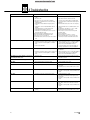
6 Troubleshooting
Problem
No sound.
Possible Cause
1. AC adapter is not connected to receiver and/or power
outlet.
2. Receiver is OFF.
3. Receiver is not connected to mixer or amplifier.
4. Microphone or instrument is not connected to bodypack transmitter.
5. Transmitter is tuned to different frequency than receiver.
6. Transmitter is "OFF" or transmitter MUTE switch at
"MUTE".
7. Transmitter batteries are not inserted properly.
8. Transmitter batteries/battery pack dead.
9. Transmitter is too far away from receiver or squelch
threshold setting is too high.
10. Obstructions between transmitter and receiver.
11. Receiver is invisible from transmitter location.
12. Receiver too close to metal objects.
13. Transmitter and receiver Preset versions are not identical.
Remedy
1. Connect AC adapter to receiver and/or power outlet.
2. Push ON/OFF switch to switch receiver ON.
3. Connect receiver output to mixer or amplifier input.
4. Connect microphone or instrument to audio input on
bodypack.
5. Tune transmitter and receiver to the same frequency.
6. Switch transmitter "ON" or set MUTE switch to ”ON”
position.
7. Insert batteries conforming to "+" and "-" marks.
8. Replace batteries/charge battery pack.
9. Move closer to receiver or choose lower squelch
threshold setting.
10. Remove obstructions.
11. Avoid spots where you cannot see receiver.
12. Remove offending objects or move receiver away.
13. Check Preset versions on transmitter and receiver.
Noise, crackling, unwanted signals.
1. Antenna location.
1. Relocate receiver or antennas.
2. Interference from other wireless systems, TV, radio, CB 2. Switch off interference sources or defective appliances
radios, or defective electrical appliances or installaor tune transmitter and receiver to a different fretions.
quency; have electrical installation checked.
3. Power voltage deviations.
3. Check power voltage and set up power supply conforming to specifications of connected equipment.
Distortion.
1. GAIN control on transmitter is set too high or too low.
Momentary loss of sound ("dropouts") at some locations within performance area.
• Antenna location.
1. Decrease or increase GAIN setting just enough to stop
the distortion.
2. Interference from other wireless systems, TV, radio, CB 2. Switch off interference sources or defective appliances
radios, or defective electrical appliances or installaor tune transmitter and receiver to a different fretions.
quency; have electrical installation checked.
Receiver Error Message
• Relocate receiver or antennas. If dead spots persist,
mark and avoid them.
Problem
Remedy
ERR.>PRG<
• Microcontroller unable to load any program.
• Contact your AKG Service Center.
ERR.>SYS<
• Frequency settings cannot be changed.
1. Switch power to receiver OFF and back ON after about
10 seconds.
2. If problem persists, contact your AKG Service Center.
ERR.>USR<
• Last setting cannot be loaded.
1. Set frequency and squelch threshold again.
2. If problem occurs frequently, contact your AKG Service
Center.
ERR.>FRE<
• Frequencies cannot be set from Frequency menu.
1. Continue with previous setting.
2. Press SETUP control briefly and set frequency from
Preset menu.
3. If problem occurs frequently, contact your AKG Service
Center.
ERR.>PRE<
• Error in selected Preset.
1. Continue with previous Preset.
2. Turn SETUP control CW or CCW to select error-free
Preset.
3. If problem occurs frequently, contact your AKG Service
Center.
ERR.>RF<
• PLL error. (Receiver cannot lock on to selected frequency.)
1. Press SETUP control briefly and set different frequency.
2. If problem persists, contact your AKG Service Center.
28
SR 4500
7 Specifications
RF carrier frequency bands:
Carrier frequencies:
Modulation:
Rated deviation:
Squelch threshold:
Audio bandwidth:
THD at 1 kHz:
Signal-to-noise:
Audio outputs:
Current consumption:
Power Requirement:
Dimensions:
Weight:
500 to 530, 570 to 600 to 680, 680 to 710, 720 to 750, 760 to 790, 790 to 820, 835 to 862 MHz
up to 1,200 per band (depending on local frequency plans)
FM
20 kHz at 1 kHz (sine wave)
adjustable between -70 and -100 dBm
35 to 20,000 Hz
<0.3% at rated deviation
118 dB(A) typical
- BALANCED 3-pin XLR, adjustable to -30, 0, +6 dB
- unbalanced 1/4" TS jack
400 mA typical
12 VDC from external power supply
200 x 44 x 190 mm (7.8 x 1.7 x 7.4 in.)
972 g (2.2 lbs.)
This product conforms to the standards listed in the Declaration of Conformity. To order a free copy of the Declaration of Conformity, visit http://www.akg.com or
contact [email protected].
SR 4500
29
Notizen • Notes • Notes • Note • Notas • Notas
86
SR 4500
Notizen • Notes • Notes • Note • Notas • Notas SR 4500
87
Mikrofone · Kopfhörer · Drahtlosmikrofone · Drahtloskopfhörer · Kopfsprechgarnituren · Akustische Komponenten
Microphones · Headphones · Wireless Microphones · Wireless Headphones · Headsets · Electroacoustical Components
Microphones · Casques HiFi · Microphones sans fil · Casques sans fil · Micros-casques · Composants acoustiques
Microfoni · Cuffie HiFi · Microfoni senza filo · Cuffie senza filo · Cuffie-microfono · Componenti acustici
Micrófonos · Auriculares · Micrófonos inalámbricos · Auriculares inalámbricos · Auriculares con micrófono · Componentes acústicos
Microfones · Fones de ouvido · Microfones s/fios · Fones de ouvido s/fios · Microfones de cabeça · Componentes acústicos
AKG Acoustics GmbH
Lemböckgasse 21–25, A-1230 Vienna/AUSTRIA, phone: (+43-1) 86654-0*
e-mail: [email protected]
For other products and distributors worldwide visit www.akg.com
Technische Änderungen vorbehalten. Specifications subject to change without notice. Ces caractéristiques sont susceptibles de modifi-cations. Ci
riserviamo il diritto di effettuare modifiche tecniche. Nos reservamos el derecho de introducir modificaciones técnicas. Especificações sujeitas a
mudanças sem aviso prévio.
Printed in China (P.R.C.).
02/08/9100 U 12710
SR 4500
Fig. 1
7a
�
�
�
�
�
Fig. 2
�
�
12
10
�
�
11
B
�
13
�
Fig. 3
A
�
�
�
�
C
�
�
Fig. 4
A
�
�
�
�
�
�
�
�
�
�
�
�
�
B
�
�
C
�
�
�
�
�
�
D
�
�
�
�
�
�
Fig. 5
A
Fig. 6
B
�
C
�
D
�