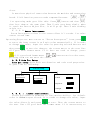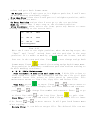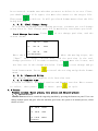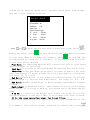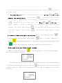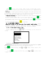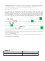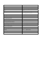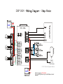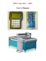
1
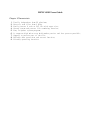
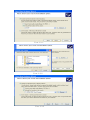
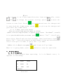
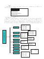
DSP Controller – 0501
User’s Manual
RZNC-0501 Users Guide
Chapter I Characteristic
1.
2.
3.
4.
5.
6.
7.
8.
9.
Totally independent from PC platform;
Directly read files from U Disk;
Easily process G code or PLT file with super size;
Strong system and process file examining function;
Easy to update system program;
It supports high micro step which makes precise and fast process possible;
Support to process part of the file;
Reliable data protection and recover function;
Friendly operating interface
Chapter II Cautions
1. Don’t use this product in strong magnetic filed or interfere environments;
2. Don’t PnP U Disk while it is running a file;
3. Protect it from water, moist, dust and fire:
4. Protect it from metal materials getting into the cover;
5. Forbad to open the cover, there is no any user maintainable parts inside;
6. Plug U Disk and other lines gentle
Chapter III Application of Host Progam
1. Host Program Setup
Host program are on the CD which include: USB drive, ZHBUSBHandHost.exe,Manual, label
file, menu file, Initial program and normal program.
1.Hardware requirements: Main-board: PIII 450;
OS: Win2000 or XP
2.Host Program Setup
1) Insert CD into computer driver, and copy all files in the CD and save them in a pointed
folder in computer, such as: C:\RZNC-0501 Host Program;
2)Connect the Controller to the computer with USB cable;
3)It shows: “Find new hardware” on the right bottom on the window as View 3-1, click
on the clue;
View 3-1
2)It appears setup information, select the second item, which is setup from list
or special location, then click on “Next” button ( as View 3-2);
View 3-2
3)Choose “include this location in the search” then click on “Browse” icon,
then find the location,such as: C:\RZNC-0501 Host Program, and click on “Next”
button to begin to setup ( as View 3-3);
View 3-3-1
View 3-3-2
View 3-3-3
4)It begins to setup driver program, click on “Continue Anyway” when it clews
“The program does not pass Microsoft Logo testing to verify its capability with
Windows XP.”,(as View 3-4);
View 3-4
7)It clews setup finished, click on “Finished”, (as View 3-5);
View 3-5-1
View 3-5-2
Chapter IV Application of Controller
Controller is the motion control system which changes motion data into related electric
signals then control the movements of the axes. Controller adopts panel and U Disk to
get files, which makes it is easy to control.
一)
Buttons function and operating means
Buttons on panel are as follows: (View 4-1)
图 4-1
4.1.1 Function
Button
Function
Positive movement of Z axis, Menu upward , figure 1 inputting
Positive movement of Y axis, accelerate process speed, figure 2 inputting,
different property selecting in Menu
Positive movement of Z axis, figure 3 inputting, rise spindle speed in
process
Working origin of X axis and Y axis setting, figure 4 inputting
Negative movement of X axis; Menu downward, figure 5 inputting
Negative movement of Y axis; slowdown process speed; figure 6 inputting
different property selecting in Menu
Negative movement of Z axis, figure 7 inputting, spindle speed adjusting in
process
Z axis origin setting ; figure 8 inputting
Axes home to machine tool origin, figure 9 inputting
Manual moving mode, high speed or low speed selection, figure 0 inputting
Spindle startup/stop, decimal point inputting
Menu setting entering, negative symbol inputting, multi process state checking,
All axes go working origin: confirm of motions /inputting/operating
Manual move, continue, step and distance modes selection
Cut process running/pause/inputted words delete
High/low speed parameter adjust, Cut process stop/selections, inputting and
operating cancel
4.1.2 compound buttons
There are some compound buttons for special applications. The operating mode is: press
the first button and hold then press the second button, release the two buttons at same
time. Their functions are as following:
1.“
”+ digit button, switch working coordinate;
2.“
”+“
3.“
”+digit button,stop point process;
4.“
”+“
” button,
5.“
”+“
”,help information;
” button, C.A.D function;
advanced process;
4.1.3 Operating Means
If it is single button, press the needed button till the wanted function works
then release it; if they are compound buttons, press the first button and then the
second one and release both at the same time.
II) Home Operating
Home is the machinery origin, Goto home operating refers to make all axes go back
machinery origin. Home position depends on home sensor. Normally there are 3 sensors
in an engraving machine. Goto home operating sets up the relationship between the
machine and the working coordinates. And many system function applications rely on
this operating, such as: stop point save, power off reboot and so on.
4.2.1Goto home settings
Goto home parameter include Home Speed and Home Direction; and those parameter
should be adjusted in Menu.
Home Speed refers to that 3 axes home speed, normally Z axis home speed should
be lower than that of X and Y axes.
Home Direction refers to which direction the axes go when it is under home process.
It depends on the motor direction and Home sensor’s location and sensor’s property.
Entering Menu, cursor is on “Machine Setup” item, press
press
button
button,
move the cursor to “ Home Setup” item, repress
to enter it, the cursor is on “ Home Speed” item
automatically, press
as following:
to enter and set 3 axes speed, detailed
Home Speedmm/min
X Axis: 3000.00
Y Axis:
3000.00
Z Axis:
3000.00
图 4-1
Input the value in cursor. If it inputted wrong number, press
to delete the
previous number and then repress the right ones. After having finished
the input, press
to confirm and save the new speed for X axis.
The Cursor moves to the Y axis speed item automatically, if it is
unnecessary to change the value, press
to move to the Z axis speed
item. If it is necessary to change the speed, the same operating with
X axis. When you finish all settings, it will go to former menu.
Press
to move the cursor to “ Home Direction” item, press
enter the setting, it displays as following:
Set Home Direction
X Axis: -Dir
Y Axis:
-Dir
Z Axis:
+Dir
to
图 4-2
The cursor is on X axis home direction item automatically, press
and
to change the current setting, press
cursor to next line. Press
to move the
to confirm and save the changes and
to give up the changes and
it goes back the former menu, press
goes back the former menu.
4. 2. 2 Home operation modes
There are several home operation modes as follows:
1) When it has been supplied power, it appears on the screen: “Goto Home?”, actually
it is a question which needs your answer, press
means “ Yes” , then Z axis
moves first, When Z axis arrives its home, then X and Y move. Press
means “ No” , 3 axes do not move to their homes. Press any other buttons,
only Z axis goes to home, X and Y don’ t go home;
2) When it is in Manual state, press
When it is going home, press
and 3 axes will go home;
button to stop the operation.
4. 3 Menu Setup
4. 3. 1 Entering
When it has finished home operating, it is in Manual state, it
appears as following:
1X
888.00
MANL
1Y
888.00
F0
1Z
88.00
Continuous
Low
View 4-3
Press
to enter the menu, there are 5 parameters in Menu. It
appears as following:
MACHINE SETUP
AUTO PRO SETUP
SYSTEM SETUP
ADVANCED PRO SETUP
VERSION VIEW
View 4-4
4.3.2Machine Setup
Machine setup parameter should connect to the engraving machine
hardware, such as: drivers, I/O terminals. If these parameters are
wrong, then it leads to wrong motions, even damage to the machine and
operators. So we strongly commend users don’ t change these items, if
it is necessary to change them, please turn to authorized experts.
Pulse Equiv
Equivalent,Pulse/mm
X Axis:400.00
Y Axis:400.00
Z Axis:400.00
MACHINE SETUP
Table Size
Motor Dir
Motor Direction
X Axis:-Dir
Y Axis:-Dir
Z Axis:-Dir
Home Speed
Home Direction
Home Setup
Spindle Setup
Spindle states
Lines State
Input Volt
Output Volt
Voltage Setup
Output Pulse
Least Pulse Width
Pulse Volt
Display Pulse
C.A.DThickne
ScrewInterspac
Machine Size,mm
X Axis:1000.00
Y Axis:1000.00
Z Axis:1000.00
Screw Space mm
X Axis: 0.00
Y Axis: 0.00
Z Axis: 0.00
C.A.D
mm
0.00
thickness,
4.3.2.1Pulse Equivalent
Pulse Equivalent means the pulse number when the axis moves 1mm.
Its unit is: pulse/mm.
Pulse Equivalent=( 360degree/Step angel) *Mircostep/Screw
When it is in Pulse Equivalent item, the cursor is on X axis value,
if it is necessary to change it, input the value directly, then
press
to save the new value, the cursor moves to the next line till
it goes back the former menu. If it does not need to change, press
to exit and go back former menu.
and
buttons are in value state,
pressing them can not move the cursor.
If the pulse equivalent in the controller is different from that of
the engraving machine. The processed file size is different from the
one you set.
4. 3. 2. 2Table Size
Table size refers to the valid motion size of 3 axes. Because the
system applies the table size as the soft limit, you should set the
table size just as the number it really is. Otherwise it will show:
“ Over the limit” or it slash the beam.
when it is in Table Size item, the cursor is on X axis value, if it
to
is necessary to change it, input the value directly, then press
save the new value, the cursor moves to the next line till it goes back
the former menu. If it does not need to change, press
go back former menu.
and
to exit and
buttons are in value state, pressing them
can not move the cursor.
If the file exceeds the table size, the system will alert when it check
the data. Then you must change your file size or operate it in an other
engraving machine with bigger table size.
4. 3. 2. 3 Motor Direction
Motor direction changes the motor moving direction. This setting
affect all motion direction of 3 axes. So after changing this item, you
must change other direction settings.
when it is in Motor direction item, the cursor is on X axis direction,
if it is necessary to change it, press
or
to change property then
press
and
buttons to move the cursor to next line. If it does not
need to change, press
to exit and go back former menu.
4. 3. 2. 4Home Setup( Details are in 4.2.1)
4.3.2.5Spindle Setup
The system offers the spindle control function. If the connection
borad and the converter have been connected well, the spindle speed
can be changed during process.
It goes like this: move cursor to “ Spindle Setup” item then press
to enter. Then it shows the value of spindle state, the default
value is 2. if it needs to change, input the value directly then press
to save. And it will show the line state. Set the lines state
according to the Converter.
Means Multicast OFF state,
means ON
state,
or
to change property then press
the cursor to next line, press
and
buttons to move
to confirm all changes. If it does
not need to change, press
to exit and go back former menu.
4. 3. 2. 6Voltage Setup
Voltage Setup refers to the terminals property, which is the I/O
sensors works at high or low voltage. Down arrow symbol means it is
high voltage, while up arrow symbol means it is low voltage. It divides
to two parts: input voltage and output voltage.
Input Voltage: the front 4 are: X, Y, Z home sensor and C.A.D property.
Press
or
to change its property, and press
the cursor to next line, press
and
buttons to move
to confirm all changes. If it does
to exit and go back former menu.
not need to change, press
It is the same operating mode to the output Voltage if it needs to
change.
4. 3. 2. 7
Output Pulse
Output pulse refers to pulse parameters, such as: Least Pulse Width,
Pulse voltage, and Display.
4. 3. 2. 8
C.A.D thickness
Cutter Adjust Device(C.A.D) is to set Z axis working origin. Users
must set its thickness, otherwise the Z axis working origin is not
correct. If you have used this function, you need not to press
to
clear.
It must have physical connection between the machine and connection
board. C.A.D function process needs compound buttons: “
”+“
”
Its operating mode goes like this: Press
button and then
,
then free them at the same time. Then Z axis goes down slowly, when
it reach the Cutter Adjust Slot, it will go up. Then Z axis working
origin set.
4. 3. 2. 9 Screw Interspaces
Screw Interspaces refers to the screw offset if it needs. Its value
cannot exceed 1mm.
Operating Steps are: move cursor to “ Screw Interspaces” item, press
to enter the item, cursor is on X axis value automatically. If it needs
to change the value, input the value by pressing related buttons and
then press
to save the changes, the cursor moves to the next line
till goes back former menu. If it does not need to change, press
till it goes back former menu.
and
buttons are in value state,
pressing them can not move the cursor.
4. 3. 3 Auto Pro Setup
Auto pro setup deals with acceleration and code read properties.
It goes like as following:
Auto Pro Setup
Linear Accl:
Unit mm/sec2
600
Curv Accl:
Unit mm/sec2
G code Read Setup
Disable
F Read
600
Disp Error
Z Height
Disable
Disable
4. 3. 3. 1
Linear Acceleration
Linear Acceleration promotes to line motion ability. Its default
value is 600mm/sequae second. If it needs to change the value, input
the value directly and press
to save. Then the cursor moves to
the next line till goes back the former menu. If it unnecessary to
change it, press
till it goes back former menu.
and
buttons
are in value state, pressing them can not move the cursor. If the auto
process speed is less than 10meters/minute, the acceleration is about
300— 600mm/sec2; if the speed is more than 10meters/min, you should
adjust the acceleration value.
4. 3. 3. 2
Curve Acceleration
Curve Acceleration promotes to curve motion ability. Its default value
is 600mm/sequae second. If it needs to change the value, input the value
directly and press
to save. Then the cursor moves to the next line
till goes back the former menu. If it unnecessary to change it, press
till it goes back former menu.
and
buttons are in value
state, pressing them can not move the cursor. If the auto process speed
is
less
than
10meters/minute,
the
acceleration
is
about
300— 600mm/sec2; if the speed is more than 10meters/min, you should
adjust the acceleration value.
4. 3. 3. 3
G code Read Setup
G code read Setup means refers to the rules of reading G code file.
Because there are many special code data.
Entering the settings, the cursor is on “ F Read Disable” item,
if it needs to execute the F code in the file, then press
or
to change its property, then “ Disable” changes into “ Enable” .
“ Disable” means to ignore the F code
while “ Enable” will execute
the code. Then move
or
to move the cursor to next item.
Display Error refers to display the wrong G code file, so that user
can correct it.
Z height refers to the raising of Z axis when it finishes working.
“ Enable” means that Z axis raises to the set height after it
finishes all work. “ Disable” means that Z axis raises as the file
asks. Press
to confirm and goes back former menu, while press
to cancel the change and goes back former menu.
4. 3. 4 System Setup
System Setup deals with function configure, file format, I/O
checking, buttons check and system update.
Function Configure is to set system functions: such as it needs Power
Off protection function or not, press
means it needs Power off
protection, while
means it does not need this function; default
language, set home switch, Enable means there is a home sensor for the
or
to change Enable to Disable, which
mentioned axis, press
means the mentioned axis gets no home sensor. if there are home sensors,
GoHome Types when the system gets power supply in which mode the system
will take. Z axis value changing and saving. Emergent Stop sensor, Hard
limit sensors and so on. Press
to enter and select the different
function configure according to the clew.
Inner Format refers to format the flash disk. When you finish the
system update, you must format inner file. Move the cursor to Inner
Format item, and press
,
the screen appears as following:
Formatting..
..
..
30%
View 4-7
when it finished, it appears: “ formatted” and press
to go back
former menu.
Input Self Check refers to the system checks Input terminals
properties.
Output Self Check refers to the system checks Output terminals
properties.
Buttons Check refers to check the buttons on the panel. After
entering, press the buttons and the related ones will show the cursor.
+
。
If you want to quit, press compound buttons:
The system does not support Noise Check.
System Auto Update if it needs to update the system, user should
download the update file from our website to U disk. The insert the
disk to the controller. Move the cursor to “ System Auto Update” item,
and press
to get in, the screen appears:
Choose file:
U Disk flile list
Inner file list
View 4-8
Choose U disk file list, press
to get in, it display all files
in the U disk, move the cursor to the downloaded update file, press
to start, the update file info appears on the screen, the user must
move the cursor and read all info, then repress
the screen displays as following:
to operate next,
It is updating Normal
program, please wait..
..
40%
It is updating Initinal
program, please wait..
..
40%
It is updating Chinese
Menu please wait.
..
...
40%
It is updating English
Menu please wait.
..
...
40%
It is updating Chinese
label please wait..
..
..
40%
It is updating English
label please wait..
..
..
40%
Updated, press any button
T h e nto continue.
p r e s s ..... t o c o n f i r m u p d a t i n g .
4. 3. 5ADVANCED PRO SETUP
It refers to special applications which includes: Multiple Setup,
Stop Setup, File Maintenance, Tool Change Setup, and Password Setup.
4. 3. 5. 1Multiple Setup
If it needs to run a file for many times, there are two ways: one
is to copy all files and save it as one file in G code making software,
then download it to the controller; the other is to make a single file
and run multiple function.
You must set the multiple parameters, such as: row number, column number,
and their space, and pause time. Then press compound buttons:
+
,
and select “ Mutiple Process” , press
to begin to process.
Multiple Process operating steps are as following: when the cursor
is on the “ Mutiple Setup” , press
Row Column
Row Space Column
Pause Time
,
it appears on the screen:
View 4-9
Press
to enter, the cursor is on rows value. If it needs to
modify, input the value directly. And the cursor moves to Column
setting. then repress
former menu.
Press
to save the change and it goes back the
键 to move the cursor to “ RowSpace ColumnSpace” item.
The cursor is on Row space value, If it needs to modify, input the
value directly. And the cursor moves to Column setting. then repress
to save the change and it goes back the former menu. Space here
means the two center distance.
Press
to move the cursor to “ Pause Time” item, press
to
enter. Pause time refers the pause time when it finish one work. Input
the value directly. Repress
to save the change and it goes back
the former menu. If it does not to modify, press
to quit and goes
back former menu. If you input a negative number, when it finish a work,
it needs to press any button then it begin to work.
4. 3. 5. 2Stop Setup
Stop Setup refers to the position 3 axes move to when it finishes the
process. It includes: Stop Statue and Stop Position. If you select “ Go
Stop Position” , you must set stop position.
Press
repress
to enter settings, the cursor is on “ Stop statue” item,
, and the screen displays:
Auto motion:
Go Origin
Z up then Stop
Go Stop Postin
Hold on
图 4-10
Press
and
to move the cursor to wanted item, repress
to
select and goes back former menu.
Go Origin refers Z axis goes to its highest position, X and Y axes
go back working coordinate origin.
Z up then Stop refers that Z axis goes to its highest position, while
X and Y axes do not move.
Go Stop Position refers that 3 axes go to the set position.
Hold on refers that 3 axes stop at the finished position.
Stop Position: after select the item, press any button to enter
setting according to the screen info:
1X
800.00
SPOT
1Y
800.00
SOFF
1Z
800.00
LOW
Move to stop position
View 4-11
Move the 3 axes to the right position, when the moving stops, the
“ Spot” and “ stop” switch fast, and the position is the stop
position. If it needs to modify, you can move the 3 axes, and the
last one is the stop position. Press
to save change and go back
former menu. Press
to cancel the setting and go back former menu.
Stop position is Machinery coordinate position and has nothing to
do with working coordinate.
4. 3. 5. 3File Maintenance
File includes: U disk file and Inner file. U disk file refers to
files saved in U disk. The controller can run the file via U disk
terminal. Inner file refers to files saved in controller. File
maintenance means to View file, Copy file and Delete File.
to enter. Press
and
to move cursor to
View file: press
target file, the screen display the file line Number and contents.
press
and
to change line number and contents. Press
to go
to first line while
to the last line. Press
to quit view.
Copy file: it can copy and save U disk file or inner file to inner
file. Press
and
to move cursor. It will goes back former menu
after copying.
Delete file: it can delete target file. The deleted file can not
be recovered, so make sure whether you want to delete it or not. First,
you should select file types, the move the cursor to the target file.
Then press
to delete. It will goes back former menu after the file
being deleted.
4. 3. 5. 4Tool Change Setup
If it needs to change tools during process, you must set tool change
setup firstly. Tool change position is machinery coordinate position.
Tool Change Position: Press
screen shows:
1X
800.00
SPOT
1Y
800.00
SOFF
to set change position, and the
1Z
800.00
LOW
V
i
e
w
4
-13
Go Cutter Position
Move the 3 axes to the right position, when the moving stops, the
“ Spot” and “ stop” switch fast, and the position is the tool
change position. If it needs to modify, you can move the 3 axes, and
the last one is the change position. Press
to save change and go
back former menu. Press
to cancel the setting and go back former
menu.
4. 3. 5. 5Password Setup
The system does not support this function now.
4. 3. 6 VERSION VIEW
Version includes: Initinal version and Normal version. Move cursor
to select, then press
to enter. press
to quit.
4.4 Process
Process includes: Manual process, Auto process and Advanced process.
4.4.1Manual Process
Manual Process refers to control the engraving machine by pressing the buttons on panel. Users can
change manual speed and grid. After the machine goes home, the system is in manual process, which
shown as below:
1X 100.00
MANL
1Y 100.00
SOFF
1Z 100.00
Continuous
HIGH
View4-18
4.4.1.1Manual Speed Change and adjust
Manual Process speed can change between High speed and Low speed.
key. If it is in High speed now, press
,HIGH
button is the
on the screen changes
to LOW; if it is in Low speed , press
LOW on the screen changes
to High. Speed statue on the screen decides manual process speed.
to set speed of
Speed Adjust: In Manual process statue, press
current speed statue. The screen displays as below:
Low spd, mm/min
X Axis: 1200.00
Y Axis:
Z Axis:
Low grid
1200.00
600.00
0.100
The cursor is on X speed item, press
and
to select the target item. Then
press
to set the value. After finishing input the new value,
press
to save the value, while press
to quit. If the input
to delete the last value.
number is not correct, press
Low grid is the least feed. Its scope is from 0.05mm— 1.0mm. When
it is in Step mode, 3 axes will move as the grid distance.
The setting means of High speed is the same to Low speed.
4. 4. 1. 2Maunal Process Modes
In order to meet different requirements for manual moving, it offers three kinds of
manual moving modes, there are Continuous moving mode, Step moving mode and Space moving
mode. Users can switch moving modes by pressing
in manual state and check the
moving mode at bottom of the screen.
(1) Continuous moving mode
In this mode, users press moving direction buttons (I①, I②, I③, II①, II② and II③) and
machine tool will move as ordered direction till all buttons release. Its speed is
determined by current speed mode. Attention: if the pressing time on buttons is too short
(less than 0.5 second) and releases the button at once, the machine tool moves to and
stops at nearest step point automatically. When this moving mode ends, the machine tool
always stops at mesh point. This mode is suitable to adjust position of machine tool.
(2) Step moving mode
It always moves at low speed with a grid per second. Its step space is determined
by current grid of speed statue. This mode is suitable to adjust cut position and machine
tool position precisely.
(3) Distance moving mode
In this mode, users press moving direction buttons (
、
、
、
、
、
) and
machine tool moves to ordered location. The machine tool moves according to current speed
mode and set spaces. The moving is not influenced by grid and stops precisely at ordered
point not at grid point.
4.4.2Auto Process
Auto Process refers to run U Disk files and Inner files. Sometimes we call it file process.
Before running any file, the machine and system parameters should be set correctly.
Auto process operating steps are:
1.Set working Origin When it is in manual state, move 3 axes to proper spot where it begins to run file.
to clear X and Y axes working origin; and press
Then Press
键 to clear
Z axis working origin. If the C.D. A function has been applied, it does not need
to press
to clear Z origin.
2.Choose file:after origins have been set, press
,
the screen displays as below:
Choose file:
U Disk file list
Inner file list
Press
press
and
to move the cursor and select the file list type,
to enter the selected file list. It will show the 1st, the
2nd, and the 3rd file names on the screen. Press
one by one, and press
and
and
to move cursor
to jump two files each time. press
and select target file. while Press
to quit.
3.Process Parameter Settings: after pressing
键 button,
it
needs to set process parameters, such as: process speed, travel speed,
Z down ratio, process speed ratio, spindle speed grad, Z up height.
And the screen display as below:
Proc Spd
8000.00
Trvl Spd 8000.00
ZDownRat 1.00
Spd Rati 1.00
Spd Grad 1
Equival pulse/mm
X Axis:
500.00
Y Axis:
500.00
Z Axis:
500.00
Z up mm 100.00
press
and
to move cursor and select different item, press
modify the value. press
to
to save the new value, then move the cursor
to next item. When it finishes all changes, press
to confirm, the
system begins to check the G code data. It starts to work after all
G code data being checked.
Proc Spd: the engraving machine will process the file at this speed
when it begins to relieving.
Trvl Spd: It travels at this speed when the machine does not relieve.
ZDownRat: Z axis goes down speed ratio. In order to protect the tools
edge from damage, it needs to make the z axis goes down at a low speed.
Its scope is: 0.1— 1.0.
Spd Rati: Speed Ratio, it can reduce the process speed. So the real
process speed is: Process Spd * Spd Ratio. Its range is: 0.1— 1.0.
Spd Grad: Spindle Speed Grad. It means spindle speed when it begins
to work.
Equivalent: It displays 3 axes’ equivalents. here you can not change
these value. If it needs to modify, you should enter the menu and set
them.
Z Up mm: It refers to the Height that Z axis can go up. If the file
Z axis up height is over this limit, it will adopt this value instead.
It is the same operating steps for inner files.
When it is running the file, the screen rolls the information of file
line number, real process speed, speed ratio, remain time. press
to stop rolling and just show the current info. repress
to switch
to next info.
4. Process Adjust When it is executing the file, press
change the speed ratio, each press on
and
to
, ratio drops 0.1till the
ratio is 0.1. And speed value changes synchronically; each press
on
, speed ratio raise 0.1 till 1.0. Press
and
button to
adjust spindle speed if you have the hardware connected and got
spindle set. Each pressing on
, the spindle speed raises a grad
till the highest. Each press on
, the spindle speed drops a grad
till F1.
5 . P r o c e s s P a u s e a n d p o s i t i o n a d j u s t When it is processing, press “
to adjust three axes position, then repress “
press “
“
”
Pause”, it clews “Original?”,
” confirms your change and it processes form the new position. While press
” denies the change and it processes from the original position;
6.Process Stop and Stop Point saving
When it is processing, press “
The screen displays as below:
” stops processing, it clews to save stop point.
1X
0.000 RUN
1Y
0.000 SOFF
1Z
0.000 LOW
Save Stop pt?
If it needs to restart process form current position lately, then you should save
it and press related digit button to save as
, which means save the stop point
as NO.1 stop point.(There are 6 stop points totally). Then it displays on the screen
as below:
1X
0.000 RUN
1Y
0.000 SOFF
1Z
0.000 LOW
Save Stop pt?1
Press
to save the setting. Then 3 axes go back home origin.
If it ne eds to continue to process from the Stop Point1, press compound buttons:
“
+
”,it starts process from the stop point. The same operating steps
to stop point2, stop point3 and so on. The condition for Stop point process is
that the 3 axes must have homed before saving the stop point.
7.Power Off Protection. The system will automatically protect the process data when
the power fall down suddenly. When it gets the power supply again, press “
go back machine origin, then it clews “PowerOff reboot?” press “
” to
” to continue
” to give up.
to process unfinished work, or “
4. 4. 3ADVANCED PROCESS
Advanced process is the function for special application, which
includes: Segment Process, Multiple Process, Segment-multiple
process, Auto Copy Process, Mill Table and Tools Change.
4. 4. 3. 1Advanced process call
Press compound buttons:
below:
+
, it displays on the screen as
Advanced Process:
Segment Process
Multiple Process
Segment-Multiple
Auto Copy Process
Mill Table
Tools Change
4.4.3.1.1Segment Process
Segment Process refers that user can select the beginning line and ending line to operate.
That is we can process part of the file. The operating steps are:
1. Press
list;
to enter setting, press
2 . Press
target file;
and
to move cursor select file
to enter the file list, press
and
to select the
3.According to the clew, select beginning line number, the first
G code data displays on the screen. Press
, it display as below:
Switch to Line
1
Input the line number in cursor position. press
line number. If the value is not correct, press
4. It displays the G code data, repress
to confirm beginning
to modify;
, it displays as following:
Ending line No.
Press
it clews: Switch to Line. And input the ending line number
in cursor. Press
correct, press
to confirm ending line number. If the value is not
to adjust ;
Press
to select the 1st line and
to select the last line.
5. Then set the process parameters, details are in Auto Process.
4.4.3.1.2Multiple Process
It needs to set multiple parameters in menu, then call this function here. Operating steps are:
1. press
and
then press
to move cursor on multiple item, press
or
to enterit,
to move cursor to select file list;
2.press
to enter the file list, repress
or
to move cursor and select
target file;
3.Set process parameters, and following steps are similar with the
auto process. It works as it set. Press
parameters, repress
to cancel the view.
4.4.3.1.3Segment-multiple Process
to view the multiple
Segment-multiple Process is to process part of the file for many times. It meets the needs to run part
of the file for many times. So it needs to set the segment parameters and multiple parameters first,
then call this function here. Its operating steps are the same to multiple process.
4.4.3.1.4Auto Copy Process
Because it reads G code from U disk, it needs to check G code data each time. If it
is a larger file, the checking will cost time. So if there is some file needs to be
processed frequently, we can process this file once and save it for inner file. When
next time, it needs to run this file, we can call it easily. Because this function takes
a lot flash memory, you’d better not to change too much files into Auto Copy Process
file. And if you reset the engraving machine and system parameters, you must to reset
this operation.
Press
and
to move cursor on “ Auto Copy Process” item, press
enter, repress
repress
or
and
Then press
to select file list. press
to
to enter file list,
to select target file. Then set process parameters.
,
it clews:
Inner file, that is which file you like to save
this file. Then press
and
to move cursor and select file, press
to confirm the file. It begins to save and it goes back Manual statue when it
finishes operating.
The operating steps of Auto Copy file are the same with auto process file. There is a * symbol before
the Processed Auto Copy Process File.
4.4.3.1.5Tools Change
After having set the tool change position in menu, selecting this item and then the machine goes to the
set position and wait for changing tool.
Chapter IV RZNC - 0501 Specifications ( U disk)
Contents
Specification
Processor
160M DSP
File Memorizer
128M memorizer inside, it supports file
with any size because of adopting mobile
memorize technology
Display
LCD with 128 dot*64 dot
Communication Terminals
USB terminal and U Disk
File Format
G code , PLT files (optional)
Axes
3 axes
Help Function
Useful help information and guide
Languages
Chinese,
English,
Russia,
Japanese(optional or customize)
Operating Interface
Friendly Buttons and Menu Drive
Drive System
Step Motors
Interpolation function
linear, curve
Cutter Adjusting function
Yes
Spindle Control Function
Yes
System Data Inspect Function
Yes
Processing Data Inspect Function
Yes
Processing Position Adjusting Function
Yes
Multi Working Coordinates
It has 9 working coordinates
Stop Point Reprocessing Function
Yes
Copy Processing Function
Yes
Data protection when power off
Yes
Working Temperature
0°C to +70°C
Humidity
<90﹪
Outer Voltage
5V
Consumptions
2W
Dimensions(mm)
156*110*38
no dew no frost
France,
ÜÍÐ ðëðï ó
í
Ü
ó Í
Ó
ßÝ
ÝòßòÜò
̱±´ Í»²-±®
ÝòßòÜæ Ý«¬¬»® ß¼¶«-¬»¼ Ü»ª·½»
í
ßÝ
±©»®
«°°´§ ÜÝ îìÊñïß
©·´´ °®±¼«½»¼ ¾§ ¬¸» ÜÍÐóÞ±¿®¼ ·¬-»´ºò