1
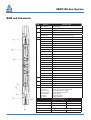
ZERO180 Gun System
MAN-Z180-000 (R00)
12001 Cr 1000
Godley, Texas, 76044, USA
Phone: +1 (817) 551-0540
Fax: +1 (817) 551-1674
www.corelab.com/owen
Warning: use of owen equipment contrary to manufacturer’s specifications or operating instructions may result in property damage, serious injury or
fatality. If you are not trained in the handling and use of explosive devices, do not attempt to use or assemble any owen perforating systems or owen
firing devices.
This technology is regulated by and, if exported, was exported from the united states in accordance with the export administration regulations (EAR).
Diversion contrary to U.S. Law is prohibited. Export and/or re-export of this technology may require issuance of a license by the bureau of industry and
security (BIS), U.S. Department of Commerce. Consult the BIS, the EAR, and/or Owen Compliance Services, Inc. To determine licensing requirements
for export or re-export of this technology.
This document contains confidential information of Owen Oil Tools LP (Owen) and is furnished to the customer for information purposes only. This
document must not be reproduced in any way whatsoever, in part or in whole, or distributed outside the customer organization, without first obtaining
the express written authorization of owen. This document is the property of owen and returnable upon request of Owen.
© 2014 Owen Oil Tools
All rights reserved
ZERO180 Gun System
TABLE OF CONTENTS
BOM and Schematic....................................................................................................3
BOM and Schematic – WL Version............................................................................4
BOM and Schematic – TCP Version ..........................................................................5
1.0 ZERO180 Gun System Overview.......................................................................6
2.0Pre-Assembly......................................................................................................8
3.0 Loading WL Version...........................................................................................9
4.0 Loading TCP Version........................................................................................13
5.0 Arming WL Version...........................................................................................17
6.0 Arming TCP Version ........................................................................................19
© 2014 Owen Oil Tools All rights reserved
MAN-Z180-000-(R00) I i
ZERO180 Gun System
BOM and Schematic
ITEM
1
PART NO.
DESCRIPTION
30-079-0002-10
Gris Switch Sub
OOO-N569-224
O-Ring, #224, 90 Duro Nitrile - see ref. section
OOO-V569-224
O-Ring, #224, 90 Duro Viton - see ref. section
OOO-N569-216
O-Ring, #216, 90 Duro Nitrile - see ref. section
OOO-V569-216
O-Ring, #216, 90 Duro Viton - see ref. section
PUR-EBRN-000
Switch Retaining Nut
S31-0445-R02WHA
SHIP ASSY, 3-1/8 X 2FT, 4SPF, WIRELINE-HOSS, 0°-180°
S31-0545-R02WHA
SHIP ASSY, 3-1/8 X 2FT, 5SPF, WIRELINE HOSS, 0°-180°
S31-0645-R02WHA
SHIP ASSY, 3-1/8 X 2FT, 6SPF, WIRELINE HOSS, 0°-180°
S31-0445-R03WHA
SHIP ASSY, 3-1/8 X 3FT, 4SPF, WIRELINE HOSS, 0°-180°
S31-0545-R03WHA
SHIP ASSY, 3-1/8 X 3FT, 5SPF, WIRELINE HOSS, 0°-180°
S31-0645-R03WHA
SHIP ASSY, 3-1/8 X 3FT, 6SPF, WIRELINE HOSS, 0°-180°
S31-0445-R04WHA
SHIP ASSY, 3-1/8 X 4FT, 4SPF, WIRELINE HOSS, 0°-180°
S31-0545-R04WHA
SHIP ASSY, 3-1/8 X 4FT, 5SPF, WIRELINE HOSS, 0°-180°
S31-0645-R04WHA
SHIP ASSY, 3-1/8 X 4FT, 6SPF, WIRELINE HOSS, 0°-180°
S31-0445-O02WHA
SHIP ASSY, 3-1/8 X 2FT, 4SPF, WIRELINE HOSS, 0°
S31-0545-O02WHA
SHIP ASSY, 3-1/8 X 2FT, 5SPF, WIRELINE HOSS, 0°
S31-0645-O02WHA
SHIP ASSY, 3-1/8 X 2FT, 6SPF, WIRELINE HOSS, 0°
S31-0445-O03WHA
SHIP ASSY, 3-1/8 X 3FT, 4SPF, WIRELINE HOSS, 0°
S31-0545-O03WHA
SHIP ASSY, 3-1/8 X 3FT, 5SPF, WIRELINE HOSS, 0°
S31-0645-O03WHA
SHIP ASSY, 3-1/8 X 3FT, 6SPF, WIRELINE HOSS, 0°
S31-0445-O04WHA
SHIP ASSY, 3-1/8 X 4FT, 4SPF, WIRELINE HOSS, 0°
S31-0545-O04WHA
SHIP ASSY, 3-1/8 X 4FT, 5SPF, WIRELINE HOSS, 0°
S31-0645-O04WHA
SHIP ASSY, 3-1/8 X 4FT, 6SPF, WIRELINE HOSS, 0°
OOO-N569-230
O-Ring, #230, 90 Duro Nitrile - see ref. section
OOO-V569-230
O-Ring, #230, 90 Duro Viton - see ref. section
SFS-N
Select Fire Switch Negative
SFS-P
Select Fire Switch Positive
9
DET-3050-429
Bi-Directional Booster
C
SDP-2715-310
SDP-2715-410
SDP-2750-311NT4
SDP-2750-411NT4
TAG-2750-401BH
TAG-2750-311
TAG-2750-411
Charge, RDX, SDP-HERO®-HARD ROCK
Charge, HMX, SDP-HERO®-HARD ROCK
Charge, RDX, SDP-NT4 - HERO®
Charge, HMX, SDP-NT4 - HERO®
Charge, HMX, BH
Charge, RDX, GH/DP
Charge, HMX, GH/DP
3
4
5
6
7
8
SPECIFICATIONS
PRESSURE RATING
144.8 Mpa
21,000 psi
TEMPERATURE
UP to 260°C
UP to 500°F
TENSILE STENGTH
89,000 daN
200,000 lbf
CARRIER THREAD
TORSIONAL YIELD
© 2014 Owen Oil Tools All rights reserved
2-3/4” - 6 STUB ACME
4,475 N*m
3,300 lb-ft
MAN-Z180-000-(R00) I 1
ZERO180 Gun System
2 I MAN-Z180-000-(R00)
© 2014 Owen Oil Tools All rights reserved
ZERO180 Gun System
BOM and Schematic – WL Version:
OD
SHOT
DENSITY
PHASING
LENGTH
# SHOTS
S31-0445-O02WHA
3 1/8
4
0
2
3
S31-0445-O03WHA
3 1/8
4
0
3
7
S31-0445-O04WHA
3 1/8
4
0
4
11
S31-0445-R02WHA
3 1/8
4
180
2
3
S31-0445-R03WHA
3 1/8
4
180
3
7
S31-0445-R04WHA
3 1/8
4
180
4
11
S31-0545-O02WHA
3 1/8
5
0
2
3
S31-0545-O03WHA
3 1/8
5
0
3
8
S31-0545-O04WHA
3 1/8
5
0
4
13
S31-0545-R02WHA
3 1/8
5
180
2
3
S31-0545-R03WHA
3 1/8
5
180
3
8
S31-0545-R04WHA
3 1/8
5
180
4
13
S31-0645-O02WHA
3 1/8
6
0
2
4
S31-0645-O03WHA
3 1/8
6
0
3
10
S31-0645-O04WHA
3 1/8
6
0
4
16
S31-0645-R02WHA
3 1/8
6
180
2
4
S31-0645-R03WHA
3 1/8
6
180
3
10
S31-0645-R04WHA
3 1/8
6
180
4
16
PART NUMBER
© 2014 Owen Oil Tools All rights reserved
MAN-Z180-000-(R00) I 3
ZERO180 Gun System
4 I MAN-Z180-000-(R00)
© 2014 Owen Oil Tools All rights reserved
BOM and Schematic – TCP Version:
OD
SHOT
DENSITY
PHASING
LENGTH
# SHOTS
S31-0445-O02THA
3 1/8
4
0
2
3
S31-0445-O03THA
3 1/8
4
0
3
7
S31-0445-O04THA
3 1/8
4
0
4
11
S31-0445-R02THA
3 1/8
4
180
2
3
S31-0445-R03THA
3 1/8
4
180
3
7
S31-0445-R04THA
3 1/8
4
180
4
11
S31-0545-O02THA
3 1/8
5
0
2
3
S31-0545-O03THA
3 1/8
5
0
3
8
S31-0545-O04THA
3 1/8
5
0
4
13
S31-0545-R02THA
3 1/8
5
180
2
3
S31-0545-R03THA
3 1/8
5
180
3
8
S31-0545-R04THA
3 1/8
5
180
4
13
S31-0645-O02THA
3 1/8
6
0
2
4
S31-0645-O03THA
3 1/8
6
0
3
10
S31-0645-O04THA
3 1/8
6
0
4
16
S31-0645-R02THA
3 1/8
6
180
2
4
S31-0645-R03THA
3 1/8
6
180
3
10
S31-0645-R04THA
3 1/8
6
180
4
16
PART NUMBER
© 2014 Owen Oil Tools All rights reserved
MAN-Z180-000-(R00) I 5
ZERO180 Gun System
6 I MAN-Z180-000-(R00)
© 2014 Owen Oil Tools All rights reserved
ZERO180 Gun System
Warning: Shot gun systems may trap pressure which can
be hazardous to personnel. If the gun components trap pressure,
maintain a safe distance from the carrier and slowly remove the gun
sub until the o-rings are exposed and the pressure safely vents.
1.0 ZERO180 Gun System Overview
Owen Oil Tools offers a wide variety of Threaded Gun systems; varying in OD size, length of carrier,
the number of shots per foot (SPF), phasing of charges, charge type, and explosive materials. The
ZERO180® Gun system is unique and patent protected.
The procedures in this manual are strictly a suggested method for loading and arming the ZERO180®
Gun system with explosive components. It is understood that each customer or company may have
their own rules, procedures, or recommended method of loading perforating guns. Owen Oil Tools
does not want to contradict these procedures in any way or form. We strongly suggest that our
customers observe and abide by all the rules and regulations pertaining to the handling, storage and
transportation of explosive components.
With this system the shaped charge seats all the way through the tube strip after the detonating cord
has already been installed. Each charge is held in place by a bend tab (no Det Cord Clip required).
This system features a round hole with slots in the tube strip.
Using Threaded Gun Subs
There are many types of subs that can be used with Owen Threaded Gun Systems. Often these
subs can be used several times without problems. However, over time, these subs can and will swell.
Because of this, Owen recommends using the graphic and chart below to reference maximum sub.
© 2014 Owen Oil Tools All rights reserved
MAN-Z180-000-(R00) I 7
ZERO180 Gun System
GUN OD
MAX. DIAMETER (IN.)
MAX. DIAMETER (MM.)
(IN.)
(A)
(B)
(A)
(B)
3.125
2.812
2.816
71.42
71.53
The gun subs used with the Owen Threaded Gun Systems are designed for a range of applications
including high pressure and temperature as well as high bending and tensile loads. For high pressure
and temperature applications o-ring backups may be required (refer to Technical Information, O-Ring
Specifications for details). It is recommended that each gun sub be tightened to the carrier and
torqued with the appropriate equipment. Refer to recommended torque values below.
RECOMMENDED MAKE UP TORQUE
GUN SYSTEM
3.125
MINIMUM
MAXIMUM
YIELD TORQUE
FT-LBF
N-M
FT-LBF
N-M
FT-LBF
N-M
600
814
1650
2239
3300
4478
Example:
T = FXd = 200 lbs.X 3 ft. = 600 lb. ft.
F = Applied Force (lb.)
d = length of the pipe wrench (ft.)
8 I MAN-Z180-000-(R00)
© 2014 Owen Oil Tools All rights reserved
ZERO180 Gun System
2.0 Pre-Assembly
Warning: Explosives are destructive by nature! Do not attempt
to disassemble or alter explosive products in any manner! Do not
crush, hammer, pinch, impact, pull wires or abuse any explosive
product!
Warning: Always be sure to follow safe operating practices as
found in API RP-67 in accordance with governmental regulations,
company policies and manufacturer’s recommendations!
Note: Before loading, visually inspect the carrier and components for
any defects and make sure that all threads and seal bores are clean.
Once you have obtained all the necessary hardware and explosives for your particular job application,
there are a few steps that will assist you in a successful operation.
2.1 Place the gun on a loading table or workbench and remove the shipping caps from each end.
The gun is identical on each end. Designate one end as top of gun and the other as bottom.
2.2 Remove the snap ring from the designated bottom of gun. With a wooden broom handle,
push the tube assembly with endplates out the bottom end of the gun and place it on the
loading table or workbench. On the tube strip, designate one end as the top of the tube and
the other as bottom. It is important to push the tube because the endplates are not secured
to the tube strip and may separate if pulled.
2.3 Look down the inside of the empty gun body from the bottom end of the gun. Rotate the
empty gun body so that the gap between the ears of the snap ring (on the top end of gun) is
in the 9 o’clock position. On the bottom end of gun, mark the outside of the gun body with a
line at the 12 o’clock position.
2.4 Remove the thru wire holder from the endplates and set aside (WL Version only).
2.5 It may also be important to mark the outside of the carriers to correspond with the zones to be
perforated. Start with the bottom shot and measure upward. Don’t forget to take into account
the lengths of any subs which will be used to connect the carriers together. Mark these zones
clearly and label accordingly on the gun body and the tube strip.
© 2014 Owen Oil Tools All rights reserved
MAN-Z180-000-(R00) I 9
ZERO180 Gun System
3.0 Loading WL Version
The detonating cord on this style, is placed on the inside of the tube strip and spirals around,
connecting the charges forming the explosive sequence. Do not to remove the endplates at this
time.
Note: With the internal wrap style tube strip, the det cord is held in
place by the charge and tube strip (no Det Cord Clips are required).
3.1 Using Owen Super Cutters, cut a sufficient length of det cord that will completely load
your tube strip and that will allow for det cord initiation. One method of doing this, is to lay
the det cord on the tube strip following the charge holes. Take that length and add 3 - 4 ft
(0.9 -1.2m). It is always better to have too much, than not enough.
Note: To determine the next length of det cord to be cut, measure
the first cut length before loading, then measure the scrap length
when finished. Subtract the scrap length from the original cut length to
determine the length of the next piece of det cord.
Warning: Never load a tube strip when the det cord is still
attached to the roll! Cut the necessary length of cord, the remove
the roll from the loading area!
3.2 Insert the det cord through end plate and tube strip on the designated bottom of the tube
strip.
3.3 Allow the det cord to exit the tube strip at the first charge. Make a 6” long loop at the det cord
and secure this configuration with electrical tape. Insert the det cord back into the tube strip
and push it along the center of the tube until it contacts the endplate at the top of the tube
strip. The excess det cord in the loop insures the switch receives a sufficient pressure pulse
to set properly and aids in the installation of det cord in the tube.
10 I MAN-Z180-000-(R00)
© 2014 Owen Oil Tools All rights reserved
ZERO180 Gun System
3.4 To load the charges, start at the top of the tube strip and insert a charge through the large
hole until the det cord grooves of the charge sticks out through the small hole (you may need
to rotate the charge so that the det cord groove aligns with the path of the det cord). Secure
in place by using the bend tab on the tube strip. The charge should not be able to move side
to side. Continue to load the required charges to complete the tube strip.
3.5 Make a clean, squared-off cut of the det cord 4.0 in. (10 cm) from the recessed face of the end
plate to install an end seal. Cut 3.25 in. (8.25 cm) if using a bi-directional booster as originally
designed.
3.6 Visually inspect the cut, then install the proper end seal or booster over the end of the det
cord and crimp in place by using Owen Super Crimpers.
3.7 Using a pair of wire cutters, cut a sufficient length of 22 gauge, 19 strand, Teflon insulated
wire that will completely pass through the thru wire holder and allow for electrical connection
through the gun. One method of doing this, is to add 3 - 4 ft. (0.9 -1.2 m) to the length of the
thru wire holder. It is always better to have too much, than not enough.
3.8 Pass the insulated wire through the thru wire holder and strip the insulation back from each
end approximately 2”.
3.9 Install the thru wire holder back on the endplates in the appropriate slot. Loop approximately
12” of the insulated wire back into the hole in the top end plate.
Note: The carrier to be loaded must be on sturdy supports and be at
an elevation of such to make inserting the loaded tube strip easy and safe.
3.10 The empty gun body should be positioned with the visible mark on the gun body at 12 o’clock
(The gap between the ears of the endplate will be at 9 0’clock when looking from the bottom
of gun).
3.11 Lift the loaded tube strip from the loading bench and carry it to the accompanying carrier. Use
as many people as necessary to safely handle the tube strip. Position then tube strip with the
thru wire holder on top or at 12 o’clock.
Note: It is important for the ZERO180® system to have the ability
to move freely within the carrier. Do not tie down charge tube or other
components restricting motion of the system. The system must be able to
move freely within the carrier.
© 2014 Owen Oil Tools All rights reserved
MAN-Z180-000-(R00) I 11
ZERO180 Gun System
Warning: A loaded tube strip can be very heavy, especially
the larger diameter tube strips, and must be handled accordingly to
prevent personal injury, dropping or bending the tube strip!
3.12 With the thru wire holder positioned at 12 o’clock, slowly slide the loaded tube strip into the
carrier. Be careful not to cause any damage to the components of the loaded tube strip.
Note: When inserting the tube strip; the roll pin on the top end plate
should fit in the gap between the ears of the snap ring. Verify the roll pin
position between the gap before proceeding.
Warning: If any difficulty is encountered while inserting
the tube strip, STOP and check for the cause of the difficulty! If
necessary, pull the tube strip back out of the carrier and determine
the problem! Never beat or force a loaded tube strip into a carrier!
3.13 With the End Plate against the Snap Ring at the top of gun, install the bottom Snap Ring with
the roll pin positioned in the gap between the ears. Be careful not to pinch the det cord or the
thru wire with the snap ring. The loaded tube strip is now secured in the gun body.
Note: You may wish to check the continuity of the thru wire for an
open or a short to the gun body at this time.
3.14 Install the proper top sub (if top gun) or select-fire tandem sub at top of gun.
For top gun: Place the size 230 O-rings on the sub. Pass the thru wire through the top sub.
Apply grease to threads and O-rings of the sub, and thread it into carrier and tighten. Attach
thru wire to appropriate electrical contact (spring boot assembly or contact block), insulate
the connection, and secure to top sub while pulling out the slack in thru wire from bottom of
gun.
Other than top gun: The select-fire tandem complete with pressure switch or dual diode
should already be installed in the bottom of the previously assembled gun. Slide a short
piece of silicon tubing (insulation for pin on switch) and retainer nut onto the thru wire. Make
a mechanical and electrical connection from the thru wire to the pin of switch, insulate it
with tubing, and install retainer nut to secure switch in tandem. Apply grease to threads and
O-rings of the sub and thread it into the assembled gun onto the tandem while pulling out the
slack in thru wire from bottom of gun.
12 I MAN-Z180-000-(R00)
© 2014 Owen Oil Tools All rights reserved
ZERO180 Gun System
3.15 The next step is to install select-fire tandem sub at bottom of gun. This system requires a
select fire tandem at the bottom of each gun. Place the size 230 o-rings on the sub. Pass the
thru wire through the tandem. Insert the tip of the end seal or booster into the 9/16” ID hole in
the tandem sub.
Warning: If any difficulty is encountered while inserting the
tandem sub, STOP and check for the cause of the difficulty! If
necessary, remove the tandem sub from the gun body and determine
the problem! Never beat or force the tandem sub into the loaded tube
strip into a carrier!
Apply grease to threads and o-rings of the sub and thread it into carrier. Before the second
o-ring engages during assembly, verify the end seal or booster has moved along the 9/16” ID
by feeling for it with a finger through the port. Once verified, finish threading the tandem and
tighten the sub while pulling out the slack in thru wire from bottom of sub.
3.16 Rotate the gun string assembly on the workbench where the port in the tandem sub is visible.
From inside the port, grab the thru wire and pull it back thru the port.
3.17 Attach a ground wire to the tandem sub in the bottom of the port. Cut a minimum of 12” piece
of 22 gauge buss wire (bare, non-insulated wire).
O-ring method: Coil 6” of the bare wire around the cross section of a size 216 o-ring leaving
approximately 6” of bare wire for making a ground connection to detonator while arming.
Snap ring method: Coil 6” of the bare wire around the cross section of a size 0125 internal
snap ring leaving approximately 6” of bare wire for making a ground connection to detonator
while arming.
3.18 Insert the o-ring or snap ring into the bottom of the port and allow the free end of the wire to
exit the port.
3.19 Choose the appropriate polarity pressure switch or dual diode and pass the wires into the sub
and out the port. Apply minimal grease to the o-rings of switch/diode and seat it in in place
with care not to push on switch pin or not to pinch wires.
3.20 Electrically connect and insulate the thru wire of the gun to the input wire of the switch/diode
(yellow for switch and white for diode). Keep the wires as short as possible to allow room for
© 2014 Owen Oil Tools All rights reserved
MAN-Z180-000-(R00) I 13
ZERO180 Gun System
all connections in port and prevent knicked or cut wires. Carefully tuck the new connection
into the bottom of the port. Also, carefully tuck the other wire from the switch/diode and the
bare wire into the port to prevent damage to either wire.
Note: You may wish to check the continuity of the thru wire and
electrical connections for an open or a short to the gun body at this time
from the top sub to the pin of the switch/diode.
Repeat steps 3.1 – 3.13 for loading each gun and steps 3.14 – 3.20 for assembling the gun string.
On the bottom gun place either a plug and shoot sub or blank gun and bull plug as appropriate.
3.21 Install the appropriate port plugs into each select-fire tandem taking care not to knick or cut
the wire during insertion.
3.22 Perform any additional necessary actions to prepare gun(s) for storage or transportation.
4.0 Loading TCP Version
The detonating cord on this style, is placed on the inside of the tube strip and spirals around,
connecting the charges forming the explosive sequence. Do not to remove the endplates at this time.
Note: With the internal wrap style tube strip, the det cord is held in
place by the charge and tube strip (no Det Cord Clips are required).
4.1 Using Owen Super Cutters, cut a sufficient length of det cord that will completely load your
tube strip and that will allow for det cord initiation. One method of doing this, is to lay the det
cord on the tube strip following the charge holes. Take that length and add 3 - 4 ft (0.9 -1.2m).
It is always better to have too much, than not enough.
Note: To determine the next length of det cord to be cut, measure
the first cut length before loading, then measure the scrap length
when finished. Subtract the scrap length from the original cut length to
determine the length of the next piece of det cord.
14 I MAN-Z180-000-(R00)
© 2014 Owen Oil Tools All rights reserved
ZERO180 Gun System
Warning: Never load a tube strip when the det cord is still
4.2
attached to the roll! Cut the necessary length of cord, the remove
the roll from the loading area!
Place the det cord through the tube strip and both end plates.
Note: To help run the cord through the tube strip, use a non-sparking
4.3
Fish Tape or Fish Tape Leader (used by electricians and plumbers).
Insert the fish tape through tube strip and attach det cord to its end using
electrical tape. Withdraw the fish tape, pulling det cord through tube strip.
Be careful not to scrape the outer covering of the cord as the fish tape is
retracted.
Install the crimp tube support (provided in the booster transfer kit) over the end of the det cord
on designated bottom end of gun with the flared end of the crimp tube support near the end
of cord.
4.4 Make a clean, squared-off cut on the bottom end of the det cord by using Owen Super
Cutters.
4.5 Visually inspect the cut, then install the proper Bi-directional Booster over the end of the det
cord and crimp in place by using Owen Super Crimpers. The crimp support tube will not be
crimped to the cord at this time.
4.6 Slide the short booster retainer tube over the booster and det cord and thread the short
booster retainer tube into the end plate making sure that the booster stays against the internal
stop of the short booster retainer tube. Also make sure crimp support tube is pushed into the
endplate and protrudes out the opposite side of endplate. Tighten firmly by hand. No rubber
grommets will be used in this system.
© 2014 Owen Oil Tools All rights reserved
MAN-Z180-000-(R00) I 15
ZERO180 Gun System
4.7 Remove the endplate with booster and booster tube from the tube strip. Crimp the crimp
support tube to the det cord while pulling slight tension on the crimp support tube using Owen
Super Crimpers.
4.8 Re-install the endplate into the tube strip without pressing on the booster or booster tube.
4.9
To load the charges, start at the bottom of the tube strip and insert a charge through the large
hole until the det cord grooves of the charge sticks out through the small hole (you may need
to rotate the charge so that the det cord groove aligns with the path of the det cord). Secure in
place by using the bend tab on the tube strip. The charge should not be able to move side to
side. Continue to load the required charges to complete the tube strip. Insert only the number
of charges that you need loaded. The tube strip can be fully or partially loaded.
4.10 Install the scale or ruler onto the Owen Super Cutters. Holding slight tension on the cord,
make a clean, squared-off cut of the det cord 7.5 in. (19.05 cm) from the face of the top end
plate.
4.11 Visually inspect the cut, then install the proper Bi-directional Booster over the end of the det
cord and crimp in place by using Owen Super Crimpers.
4.12 Slide the long booster support tube over the booster and det cord and thread into end plate.
As you thread in the tube, the booster should be positioned flush with the end of the booster
tube. Tighten firmly by hand. No rubber grommets will be used in this system.
Note: The carrier to be loaded must be on sturdy supports and be
at an elevation of such to make inserting the loaded tube strip easy and
safe.
4.13 Lift the loaded tube strip from the loading bench and carry it to the accompanying carrier. Use
as many people as necessary to safely handle the tube strip.
Note: It is important for the ZERO180® system to have the ability
to move freely within the carrier. Do not tie down charge tube or other
components restricting motion of the system. The system must be able to
move freely within the carrier.
16 I MAN-Z180-000-(R00)
© 2014 Owen Oil Tools All rights reserved
ZERO180 Gun System
Warning: A loaded tube strip can be very heavy, especially
the larger diameter tube strips, and must be handled accordingly to
prevent personal injury, dropping or bending the tube strip!
Caution:
Do not damage or break the Booster Transfer Tube (if
applicable), during insertion! Do not pinch the det cord or Booster
during insertion!
4.14 Slowly slide the loaded tube strip into the carrier. Be careful not to cause any damage to the
components of the loaded tube strip.
Warning: If any difficulty is encountered while inserting
the tube strip, STOP and check for the cause of the difficulty! If
necessary, pull the tube strip back out of the carrier and determine
the problem! Never beat or force a loaded tube strip into a carrier!
4.15 With the End Plate against the Snap Ring at the top of gun, install the bottom Snap Ring. The
loaded tube strip is now secured in the gun body.
4.16 Install the proper top sub or tandem sub at top of gun. Place the size 230 O-rings on the sub.
Apply grease to threads and O-rings of the sub, and thread it into carrier and tighten.
4.17 Install an alignment insert and o-ring (provided in the booster transfer kit) into the sub.
Repeat steps 4.1 – 4.17 for loading and assembling each gun.
4.18 Perform any additional necessary actions to prepare gun(s) for storage or transportation.
© 2014 Owen Oil Tools All rights reserved
MAN-Z180-000-(R00) I 17
ZERO180 Gun System
5.0 Arming WL Version
The ZERO180® gun system should be armed according to each company’s standard operating
procedures. While the guns themselves are unique, the assembly method and connections external
to the guns or gun string are not. The ballistic connection of the detonator to det cord is unique and
will be covered in this section.
Warning: Explosives are destructive by nature! Do not attempt
to disassemble or alter the detonator in any manner! Do not crush,
hammer, pinch, impact, pull wires or abuse the detonator or any
explosive!
Warning: Be sure to follow safe operating practices as found in
API RP-67 in accordance with governmental regulations, company
policies and manufacturer’s recommendations!
The following steps as a minimum should be completed prior to commencing the arming procedures:
• Hazard Identification and Resolution
• Safety Meeting
• Stray Voltage Check
• Installation of grounding cables
• Check Fire through logging equipment (not perforating equipment)
• Power down all power sources and rf devices
• Remove safety key from inside of WL operating unit
• Attach perforating equipment to the WL cable
• Verify no voltage exists at the electrical connections of the gun
Warning: Detonators should be removed from their packaging
and storage in the loading/arming area at the time of arming!
Always insert the detonator inside a safety tube after removal from
packaging and storage!
18 I MAN-Z180-000-(R00)
© 2014 Owen Oil Tools All rights reserved
ZERO180 Gun System
Caution:
It is recommended to handle one detonator at a time
to minimize the hazards; furthermore, arm each gun individually
from the top of the gun string working towards the bottom to reduce
exposure and risk.
5.1 Remove an Austin Powder A-140F detonator from its storage container and packaging.
Discard the plastic detonator block; it is not required for this system.
5.2 Place a pencil at the wire end of the detonator. Bend the detonator lead wires around the
pencil back to the body of the detonator taking care not to pull on the wires. Secure the wires
to the body of the detonator with 2 – 3 wraps of electrical tape around the wires and detonator.
Do not cover the fluid holes of the detonator. Bend the wires back in their original direction.
This step will prevent you from pulling the lead wires directly on the end of the detonator.
5.3 Insert the detonator into a detonator safety tube and secure the lid closed.
5.4 Remove the electrical shunt from the wires and verify the resistance of the meter with a
blaster’s multimeter or blaster’s galvanometer. The resistance of the detonator should read
between 50 and 60 Ohms.
5.5 Through the port, electrically connect the ground wire of the gun to the purple wire of the
detonator. Since this is the ground no insulation of the connection is necessary. Keep the
wires as short as possible to allow room for all connections in port and prevent knicked or cut
wires.
5.6 Also through the port, electrically connect and insulate the wire from the switch/diode to the
red wire of the detonator. Keep the wires as short as possible to allow room for all connections
in port and prevent knicked or cut wires.
5.7
The detonator is fully connected electrically. Remove the detonator from the detonator safety
tube. Insert the detonator, output end first, through the port and into the 9/16” hole in the sub.
(It is important to use sub 30-079-0002-95 as it has the correct confinement for lap splice
initiation.) The detonator is positioned next to the det cord and is now ballistically armed.
5.8 Carefully tuck the new connections into the bottom of the port.
© 2014 Owen Oil Tools All rights reserved
MAN-Z180-000-(R00) I 19
ZERO180 Gun System
5.9
Install a size -224 o-ring on the port hole and a size -216 o-ring on the port plug if not completed
prior. Apply a minimal amount of grease to threads and o-rings. Thread the port plug into the
tandem taking care not to knick or cut the wires and tighten.
Repeat steps 5.1 – 5.9 to arm each gun.
5.10 Perform any additional necessary actions to prepare gun string for conveyance in well.
6.0 Arming TCP Version
The ZERO180® gun system should be armed according to each company’s standard operating
procedures, gun assembly and firing head. While the guns themselves are unique, the assembly
method and connections external to the guns or gun string including the firing heads are not.
20 I MAN-Z180-000-(R00)
© 2014 Owen Oil Tools All rights reserved