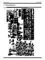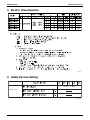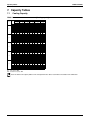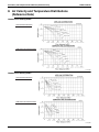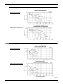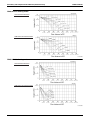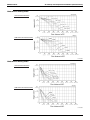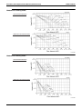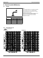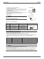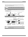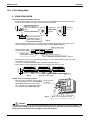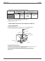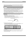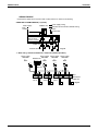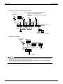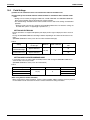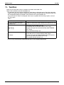
1
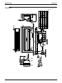
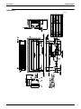
EDUS391100-F6 FXAQ-PVJU Wall Mounted Type AMERICAS EDUS391100-F6 FXAQ-PVJU Wall Mounted Type 1. Specifications ................................................................. 2 2. Dimensions..................................................................... 4 3. Piping Diagrams ............................................................. 7 4. Wiring Diagrams............................................................. 8 5. Electric Characteristics................................................... 9 6. Safety Devices Setting ................................................... 9 7. Capacity Tables............................................................ 10 7.1 Cooling Capacity ............................................................10 7.2 Heating Capacity ............................................................11 8. Air Velocity and Temperature Distributions (Reference Data) ....................................................... 12 9. Sound Levels (Reference)............................................ 17 9.1 Overall ............................................................................17 9.2 Octave Band Level .........................................................17 10. Installation .................................................................. 19 10.1 Accessories ..................................................................22 10.2 Indoor Unit Installation..................................................25 10.3 Drain Piping Work.........................................................31 10.4 Electrical Wiring Work ..................................................32 10.5 Field Settings..............................................................39 11. Test Run................................................................... 40 12. Accessories ................................................................ 41 12.1 Optional Accessories (For Controls).............................41 FXAQ-PVJU 1 Specifications EDUS391100-F6 1. Specifications Wall Mounted Type Model FXAQ07PVJU Power Supply FXAQ09PVJU FXAQ12PVJU 1 phase, 208/230V, 60Hz 1, 3 Cooling Capacity Btu/h 7,500 9,500 12,000 2, 3 Heating Capacity Btu/h 8,500 10,500 13,500 White (3.0Y8.5/0.5) White (3.0Y8.5/0.5) White (3.0Y8.5/0.5) in (mm) 11–3/8 × 31–1/4 × 9–1/4 (289 x 794 x 235) 11–3/8 × 31–1/4 × 9–1/4 (289 x 794 x 235) 11–3/8 × 31–1/4 × 9–1/4 (289 x 794 x 235) 2×14×17 2×14×17 2×14×17 1.73 1.73 1.73 QCL9661M QCL9661M QCL9661M Cross Flow Fan Casing Color Dimensions: (H×W×D) Coil (Cross Fin Coil) Rows×Stages×FPI Face Area ft² (m²) Model Type Fan Motor Output Air Flow Rate (H/L) Cross Flow Fan Cross Flow Fan W 40 40 40 cfm (m3/min) 260/160 (79/49) 280/175 (85/53) 290/180 (88/55) Drive Direct Drive Direct Drive Direct Drive Microprocessor Thermostat for Cooling and Heating Microprocessor Thermostat for Cooling and Heating Microprocessor Thermostat for Cooling and Heating Sound Absorbing Thermal Insulation Material Foamed Polystyrene / Foamed Polyethylene Foamed Polystyrene / Foamed Polyethylene Foamed Polystyrene / Foamed Polyethylene Air Filter Resin Net (Washable) Temperature Control Machine Weight (Mass) Liquid Pipes Gas Pipes Piping Connections Drain Pipe 4 Sound Level (H/L) Safety Devices Refrigerant Control Connectable outdoor unit Standard Accessories Drawing No. Resin Net (Washable) Resin Net (Washable) Lbs (kg) 26 (12) 26 (12) 26 (12) in (mm) 1/4 (6.4) (Flare Connection) 1/4 (6.4) (Flare Connection) 1/4 (6.4) (Flare Connection) in (mm) 1/2 (12.7) (Flare Connection) 1/2 (12.7) (Flare Connection) 1/2 (12.7) (Flare Connection) in (mm) VP13 (External Dia. 11/16 (17.5) Internal Dia. 1/2 (12.7)) VP13 (External Dia. 11/16 (17.5) Internal Dia. 1/2 (12.7)) VP13 (External Dia. 11/16 (17.5) Internal Dia. 1/2 (12.7)) dB(A) 36/31 37/31 38/31 Fuse Fuse Fuse Electronic Expansion Valve Electronic Expansion Valve Electronic Expansion Valve R-410A VRV Series R-410A VRV Series R-410A VRV Series Operation Manual, Installation Manual, Installation Panel, Paper Pattern for Installation, Insulation Tape, Insulation Tube, Clamps, Screws. Operation Manual, Installation Manual, Installation Panel, Paper Pattern for Installation, Insulation Tape, Insulation Tube, Clamps, Screws. Operation Manual, Installation Manual, Installation Panel, Paper Pattern for Installation, Insulation Tape, Insulation Tube, Clamps, Screws. C: 3D075572A Notes: 1 Nominal cooling capacities are based on the following conditions: Return air temperature: 80°FDB, 67°FWB (27°CDB /19.4°CWB) Outdoor temperature: 95°FDB (35°CDB) Equivalent ref. piping length: 25ft (7.5 m) (Horizontal) 2 Nominal heating capacities are based on the following conditions: Return air temperature: 70°FDB (21°CDB). Outdoor temperature: 47°FDB, 43°FWB (8.3°CDB / 6°CWB) Equivalent ref. piping length: 25ft (7.5 m) (Horizontal) 3 Capacities are net, including a deduction for cooling (an addition for heating) for indoor fan motor heat. 4 Sound levels are measured under JIS conditions. 5 Refer to page 9 for Power Input. 2 FXAQ-PVJU EDUS391100-F6 Specifications Wall Mounted Type Model FXAQ18PVJU Power Supply FXAQ24PVJU 1 phase, 208/230V, 60Hz 1, 3 Cooling Capacity Btu/h 18,000 24,000 2, 3 Heating Capacity Btu/h 20,000 26,500 White (3.0Y8.5/0.5) White (3.0Y8.5/0.5) in (mm) 11–3/8 × 41–3/8 × 9–1/4 (289 x 1051 x 235) 11–3/8 × 41–3/8 × 9–1/4 (289 x 1051 x 235) 2×14×17 2×14×17 ft² (m²) 2.29 (0.7) 2.29 (0.7) Casing Color Dimensions: (H×W×D) Coil (Cross Fin Coil) Fan Rows×Stages×FPI Face Area Model QCL9686M QCL9686M Type Cross Flow Fan Cross Flow Fan Motor Output Air Flow Rate (H/L) W 43 43 cfm (m3/min) 500/400 (152/122) 635/470 (194/143) Drive Direct Drive Direct Drive Microprocessor Thermostat for Cooling and Heating Microprocessor Thermostat for Cooling and Heating Sound Absorbing Thermal Insulation Material Foamed Polystyrene / Foamed Polyethylene Foamed Polystyrene / Foamed Polyethylene Air Filter Resin Net (Washable) Resin Net (Washable) Temperature Control Machine Weight (Mass) Piping Connections Lbs (kg) 31 (14) 31 (14) Liquid Pipes in (mm) 1/4 (6.4) (Flare Connection) 3/8 (9.5) (Flare Connection) Gas Pipes in (mm) 1/2 (12.7) (Flare Connection) 5/8 (15.8) (Flare Connection) in (mm) VP13 (External Dia. 11/16 (17.5) Internal Dia. 1/2 (12.7)) VP13 (External Dia. 11/16 (17.5) Internal Dia. 1/2 (12.7)) dB(A) 43/37 47/41 Drain Pipe 4 Sound Level (H/L) Safety Devices Refrigerant Control Connectable outdoor unit Standard Accessories Fuse Fuse Electronic Expansion Valve Electronic Expansion Valve R-410A VRV Series R-410A VRV Series Operation Manual, Installation Manual, Installation Panel, Paper Pattern for Installation, Insulation tape, Insulation Tube, Clamps, Screws. Drawing No. Operation Manual, Installation Manual, Installation Panel, Paper Pattern for Installation, Insulation tape, Insulation Tube, Clamps, Screws. C: 3D075572A Notes: 1 Nominal cooling capacities are based on the following conditions: Return air temperature: 80°FDB, 67°FWB (27°CDB /19.4°CWB) Outdoor temperature: 95°FDB (35°CDB) Equivalent ref. piping length: 25ft (7.5 m) (Horizontal) 2 Nominal heating capacities are based on the following conditions: Return air temperature: 70°FDB (21°CDB). Outdoor temperature: 47°FDB, 43°FWB (8.3°CDB / 6°CWB) Equivalent ref. piping length: 25ft (7.5 m) (Horizontal) 3 Capacities are net, including a deduction for cooling (an addition for heating) for indoor fan motor heat. 4 Sound levels are measured under JIS conditions. 5 Refer to page 9 for Power Input. FXAQ-PVJU 3 Dimensions EDUS391100-F6 2. Dimensions FXAQ07PVJU/FXAQ09PVJU/FXAQ12PVJU 3D075388A Unit (in.) 4 FXAQ-PVJU EDUS391100-F6 Dimensions FXAQ18PVJU 3D075389A Unit (in.) FXAQ-PVJU 5 Dimensions EDUS391100-F6 FXAQ24PVJU 3D075390A Unit (in.) 6 FXAQ-PVJU EDUS391100-F6 Piping Diagrams 3. Piping Diagrams C: 4D034245F Model Gas Liquid FXAQ07PVJU/FXAQ09PVJU/ FXAQ12PVJU/FXAQ18PVJU 1/2 1/4 FXAQ24PVJU 5/8 3/8 FXAQ-PVJU 7 Wiring Diagrams EDUS391100-F6 4. Wiring Diagrams 3D075354 FXAQ07PVJU/FXAQ09PVJU/FXAQ12PVJU/FXAQ18PVJU/FXAQ24PVJU 8 FXAQ-PVJU EDUS391100-F6 Electric Characteristics 5. Electric Characteristics 4D075550 6. Safety Devices Setting 250V / 3.15A FXAQ - PVJU C: 4D047085C FXAQ-PVJU 9 Capacity Tables EDUS391100-F6 7. Capacity Tables 7.1 Cooling Capacity FXAQ-P Outdoor Unit size air temp. 07 09 12 18 24 °FDB 75 79 83 87 91 95 99 103 75 79 83 87 91 95 99 103 75 79 83 87 91 95 99 103 75 79 83 87 91 95 99 103 75 79 83 87 91 95 99 103 [Cooling capacity] 61 °FWB TC SHC MBh MBh 5.9 5.6 5.9 5.6 5.9 5.6 5.9 5.6 5.9 5.6 5.9 5.6 5.9 5.6 5.9 5.6 7.5 6.5 7.5 6.5 7.5 6.5 7.5 6.5 7.5 6.5 7.5 6.5 7.5 6.5 7.5 6.5 9.5 7.9 9.5 7.9 9.5 7.9 9.5 7.9 9.5 7.9 9.5 7.9 9.5 7.9 9.5 7.9 14.2 11.7 14.2 11.7 14.2 11.7 14.2 11.7 14.2 11.7 14.2 11.7 14.2 11.7 14.2 11.7 18.9 15.3 18.9 15.3 18.9 15.3 18.9 15.3 18.9 15.3 18.9 15.3 18.9 15.3 18.9 15.3 64 °FWB TC SHC MBh MBh 6.7 6.1 6.7 6.1 6.7 6.1 6.7 6.1 6.7 6.1 6.7 6.1 6.7 6.1 6.7 6.1 8.5 7.2 8.5 7.2 8.5 7.2 8.5 7.2 8.5 7.2 8.5 7.2 8.5 7.2 8.5 7.2 10.7 8.3 10.7 8.3 10.7 8.3 10.7 8.3 10.7 8.3 10.7 8.3 10.7 8.3 10.7 8.3 16.1 12.7 16.1 12.7 16.1 12.7 16.1 12.7 16.1 12.7 16.1 12.7 16.1 12.7 16.1 12.7 21.5 16.5 21.5 16.5 21.5 16.5 21.5 16.5 21.5 16.5 21.5 16.5 21.5 16.5 21.5 16.5 Indoor air temp. 67 °FWB 70 °FWB TC SHC TC SHC MBh MBh MBh MBh 7.5 6.4 8.3 6.6 7.5 6.4 8.3 6.6 7.5 6.4 8.3 6.6 7.5 6.4 8.2 6.6 7.5 6.4 8.1 6.6 7.5 6.4 8.0 6.5 7.5 6.4 7.8 6.3 7.5 6.4 7.7 6.2 9.5 7.3 10.5 7.7 9.5 7.3 10.5 7.7 9.5 7.3 10.5 7.7 9.5 7.3 10.4 7.6 9.5 7.3 10.3 7.5 9.5 7.3 10.1 7.4 9.5 7.3 9.9 7.2 9.5 7.3 9.7 7.1 12.0 8.9 13.3 9.2 12.0 8.9 13.3 9.2 12.0 8.9 13.3 9.2 12.0 8.9 13.2 9.1 12.0 8.9 13.0 9.1 12.0 8.9 12.7 8.9 12.0 8.9 12.5 8.9 12.0 8.9 12.3 8.7 18.0 13.7 19.9 13.9 18.0 13.7 19.9 13.9 18.0 13.7 19.9 13.9 18.0 13.7 19.8 13.8 18.0 13.7 19.4 13.8 18.0 13.7 19.1 13.6 18.0 13.7 18.8 13.5 18.0 13.7 18.4 13.3 24.0 18.0 26.5 18.3 24.0 18.0 26.5 18.3 24.0 18.0 26.5 18.3 24.0 18.0 26.4 18.2 24.0 18.0 25.9 18.1 24.0 18.0 25.5 17.8 24.0 18.0 25.0 17.8 24.0 18.0 24.6 17.4 72 °FWB TC SHC MBh MBh 8.8 6.8 8.6 6.6 8.5 6.5 8.3 6.4 8.2 6.4 8.1 6.3 7.9 6.2 7.8 6.1 11.1 8.1 10.9 8.0 10.7 7.8 10.6 7.7 10.4 7.6 10.2 7.4 10.0 7.3 9.9 7.2 14.0 9.3 13.8 9.1 13.6 9.1 13.3 8.9 13.1 8.9 12.9 8.8 12.7 8.7 12.4 8.6 21.0 14.1 20.7 13.9 20.4 13.8 20.0 13.6 19.7 13.6 19.3 13.3 19.0 12.7 18.7 12.5 28.0 18.5 27.6 18.3 27.1 18.2 26.7 18.0 26.2 17.8 25.8 17.6 25.3 17.4 24.9 17.2 75 °FWB TC SHC MBh MBh 8.9 6.5 8.8 6.4 8.6 6.3 8.5 6.2 8.4 6.1 8.2 6.0 8.1 5.9 7.9 5.8 11.3 7.6 11.1 7.4 10.9 7.3 10.9 7.3 10.6 7.1 10.4 7.0 10.2 6.8 10.0 6.7 14.3 8.8 14.0 8.7 13.8 8.6 13.6 8.6 13.4 8.5 13.1 8.5 12.9 8.4 12.7 8.4 21.4 12.8 21.1 12.7 20.7 12.6 20.4 12.6 20.1 12.5 19.7 12.4 19.4 12.3 19.0 12.2 28.5 17.1 28.1 16.9 27.6 16.8 27.2 16.6 26.7 16.4 26.3 16.2 25.8 15.9 25.4 15.7 TC: Total capacity: MBh SHC: Sensible heat capacity: MBh Refer to outdoor unit capacity tables for the actual performance data of each indoor and outdoor unit combination. 10 FXAQ-PVJU EDUS391100-F6 7.2 Capacity Tables Heating Capacity FXAQ-P Unit size 07 09 12 18 24 [Heating capacity] Outdoor air temp. °FDB 22.0 26.0 30.0 35.0 39.0 44.0 47.0 51.0 54.0 57.0 60.0 22.0 26.0 30.0 35.0 39.0 44.0 47.0 51.0 54.0 57.0 60.0 22.0 26.0 30.0 35.0 39.0 44.0 47.0 51.0 54.0 57.0 60.0 22.0 26.0 30.0 35.0 39.0 44.0 47.0 51.0 54.0 57.0 60.0 22.0 26.0 30.0 35.0 39.0 44.0 47.0 51.0 54.0 57.0 60.0 °FWB 20.0 24.0 28.0 32.0 36.0 40.0 43.0 47.0 50.0 53.0 56.0 20.0 24.0 28.0 32.0 36.0 40.0 43.0 47.0 50.0 53.0 56.0 20.0 24.0 28.0 32.0 36.0 40.0 43.0 47.0 50.0 53.0 56.0 20.0 24.0 28.0 32.0 36.0 40.0 43.0 47.0 50.0 53.0 56.0 20.0 24.0 28.0 32.0 36.0 40.0 43.0 47.0 50.0 53.0 56.0 62 °FDB TC MBh 7.3 7.6 8.0 8.3 8.7 9.0 9.3 9.6 9.7 9.7 9.7 9.2 9.7 10.1 10.6 11.0 11.4 11.8 12.2 12.3 12.3 12.3 11.7 12.2 12.8 13.3 13.9 14.5 14.9 15.4 15.5 15.5 15.5 17.5 18.3 19.2 20.0 20.8 21.7 22.3 23.1 23.2 23.2 23.2 22.9 24.0 25.1 26.2 27.3 28.4 29.2 30.3 30.4 30.4 30.4 65 °FDB TC MBh 7.3 7.6 8.0 8.3 8.7 9.0 9.2 9.2 9.2 9.2 9.2 9.2 9.7 10.1 10.5 11.0 11.4 11.7 11.7 11.7 11.7 11.7 11.7 12.2 12.8 13.3 13.9 14.4 14.7 14.7 14.7 14.7 14.7 17.5 18.3 19.1 20.0 20.8 21.6 22.1 22.1 22.1 22.1 22.1 22.9 24.0 25.1 26.1 27.2 28.3 29.0 29.0 29.0 29.0 29.0 Indoor air temp. 68 °FDB 70 °FDB TC TC MBh MBh 7.3 7.3 7.6 7.6 8.0 8.0 8.3 8.3 8.7 8.4 8.7 8.5 8.7 8.5 8.7 8.5 8.7 8.5 8.7 8.5 8.7 8.5 9.2 9.2 9.6 9.6 10.1 10.1 10.5 10.5 11.0 10.5 11.1 10.5 11.1 10.5 11.1 10.5 11.1 10.5 11.1 10.5 11.1 10.5 11.6 11.6 12.2 12.2 12.7 12.7 13.3 13.3 13.9 13.5 14.0 13.5 14.0 13.5 14.0 13.5 14.0 13.5 14.0 13.5 14.0 13.5 17.4 17.4 18.3 18.3 19.1 19.1 19.9 19.9 20.8 20.0 21.0 20.0 21.0 20.0 21.0 20.0 21.0 20.0 21.0 20.0 21.0 20.0 22.8 22.8 23.9 23.9 25.0 25.0 26.1 26.1 27.2 26.5 27.5 26.5 27.5 26.5 27.5 26.5 27.5 26.5 27.5 26.5 27.5 26.5 72 °FDB TC MBh 7.3 7.6 7.9 8.1 8.1 8.1 8.1 8.1 8.1 8.1 8.1 9.2 9.6 10.1 10.3 10.3 10.3 10.3 10.3 10.3 10.3 10.3 11.6 12.2 12.7 13.0 13.0 13.0 13.0 13.0 13.0 13.0 13.0 17.4 18.2 19.1 19.5 19.5 19.5 19.5 19.5 19.5 19.5 19.5 22.8 23.9 25.0 25.5 25.5 25.5 25.5 25.5 25.5 25.5 25.5 75 °FDB TC MBh 7.2 7.6 7.7 7.7 7.7 7.7 7.7 7.7 7.7 7.7 7.7 9.2 9.6 9.7 9.7 9.7 9.7 9.7 9.7 9.7 9.7 9.7 11.6 12.1 12.3 12.3 12.3 12.3 12.3 12.3 12.3 12.3 12.3 17.4 18.2 18.4 18.4 18.4 18.4 18.4 18.4 18.4 18.4 18.4 22.7 23.8 24.0 24.0 24.0 24.0 24.0 24.0 24.0 24.0 24.0 TC: Total capacity: MBh Refer to outdoor unit capacity tables for the actual performance data of each indoor and outdoor unit combination. FXAQ-PVJU 11 Air Velocity and Temperature Distributions (Reference Data) EDUS391100-F6 8. Air Velocity and Temperature Distributions (Reference Data) FXAQ07PVJU <Cooling mode> AIRFLOW DISTRIBUTIONS TEMPERATURE DISTRIBUTIONS C: 3D053942 FXAQ07PVJU <Heating mode> AIRFLOW DISTRIBUTIONS TEMPERATURE DISTRIBUTIONS C: 3D053942 12 FXAQ-PVJU EDUS391100-F6 Air Velocity and Temperature Distributions (Reference Data) FXAQ09PVJU <Cooling mode> AIRFLOW DISTRIBUTIONS TEMPERATURE DISTRIBUTIONS C: 3D053943 FXAQ09PVJU <Heating mode> AIRFLOW DISTRIBUTIONS TEMPERATURE DISTRIBUTIONS C: 3D053943 FXAQ-PVJU 13 Air Velocity and Temperature Distributions (Reference Data) EDUS391100-F6 FXAQ12PVJU <Cooling mode> AIRFLOW DISTRIBUTIONS TEMPERATURE DISTRIBUTIONS C: 3D052935 FXAQ12PVJU <Heating mode> AIRFLOW DISTRIBUTIONS TEMPERATURE DISTRIBUTIONS C: 3D052935 14 FXAQ-PVJU EDUS391100-F6 Air Velocity and Temperature Distributions (Reference Data) FXAQ18PVJU <Cooling mode> AIRFLOW DISTRIBUTIONS TEMPERATURE DISTRIBUTIONS C: 3D052936 FXAQ18PVJU <Heating mode> AIRFLOW DISTRIBUTIONS TEMPERATURE DISTRIBUTIONS C: 3D052936 FXAQ-PVJU 15 Air Velocity and Temperature Distributions (Reference Data) EDUS391100-F6 FXAQ24PVJU <Cooling mode> AIRFLOW DISTRIBUTIONS TEMPERATURE DISTRIBUTIONS C: 3D052937 FXAQ24PVJU <Heating mode> AIRFLOW DISTRIBUTIONS TEMPERATURE DISTRIBUTIONS C: 3D052937 16 FXAQ-PVJU EDUS391100-F6 Sound Levels (Reference) 9. Sound Levels (Reference) 9.1 Overall Location of microphone Notes: 1. The operating conditions are assumed to be standard (JIS conditions). Power source 208/230V, 60Hz. 2. The operating values were obtained in an anechoic chamber (conversion values). 3. Sound levels will vary depending on a range of factors such as the construction (acoustic absorption coefficient) of the particular room in which the equipment is installed. dB(A) Model 9.2 208/230V, 60Hz H L FXAQ07PVJU 36 31 FXAQ09PVJU 37 31 FXAQ12PVJU 38 31 FXAQ18PVJU 43 37 FXAQ24PVJU 47 41 Octave Band Level 208/230V, 60Hz FXAQ07PVJU FXAQ09PVJU 4D075580 FXAQ-PVJU 4D075581 17 Sound Levels (Reference) EDUS391100-F6 FXAQ12PVJU FXAQ18PVJU 4D075582 4D075583 FXAQ24PVJU 4D075584 18 FXAQ-PVJU EDUS391100-F6 Installation 10. Installation Safety ConsiderationsRead these SAFETY CONSIDERATIONS for Installation carefully before installing an air conditioner or heat pump. After completing the installation, make sure that the unit operates properly during the startup operation. Instruct the customer on how to operate and maintain the unit. Inform customers that they should store this Installation Manual with the Operation Manual for future reference. Always use a licensed installer or contractor to install this product. Improper installation can result in water or refrigerant leakage, electrical shock, fire, or explosion. Meanings of DANGER, WARNING, CAUTION, and NOTE Symbols: DANGER .............. Indicates an imminently hazardous situation which, if not avoided, will result in death or serious injury. WARNING ............ Indicates a potentially hazardous situation which, if not avoided, could result in death or serious injury. CAUTION ............. Indicates a potentially hazardous situation which, if not avoided, may result in minor or moderate injury. It may also be used to alert against unsafe practices. NOTE .................. Indicates situations that may result in equipment or property-damage accidents only. DANGER • Refrigerant gas is heavier than air and replaces oxygen. A massive leak can lead to oxygen depletion, especially in basements, and an asphyxiation hazard could occur leading to serious injury or death. • Do not ground units to water pipes, gas pipes, telephone wires, or lightning rods as incomplete grounding can cause a severe shock hazard resulting in severe injury or death. Additionally, grounding to gas pipes could cause a gas leak and potential explosion causing severe injury or death. • If refrigerant gas leaks during installation, ventilate the area immediately. Refrigerant gas may produce toxic gas if it comes into contact with fire. Exposure to this gas could cause severe injury or death. • After completing the installation work, check that the refrigerant gas does not leak throughout the system. • Do not install unit in an area where flammable materials are present due to risk of explosions that can cause serious injury or death. • Safely dispose all packing and transportation materials in accordance with federal/state/local laws or ordinances. Packing materials such as nails and other metal or wood parts, including plastic packing materials used for transportation may cause injuries or death by suffocation. • Only qualified personnel must carry out the installation work. Installation must be done in accordance with this installation manual. Improper installation may result in water leakage, electric shock, or fire. FXAQ-PVJU • When installing the unit in a small room, take measures to keep the refrigerant concentration from exceeding allowable safety limits. Excessive refrigerant leaks, in the event of an accident in a closed ambient space, can lead to oxygen deficiency. • Use only specified accessories and parts for installation work. Failure to use specified parts may result in water leakage, electric shocks, fire, or the unit falling. • Install the air conditioner or heat pump on a foundation strong enough that it can withstand the weight of the unit. A foundation of insufficient strength may result in the unit falling and causing injuries. • Take into account strong winds, typhoons, or earthquakes when installing. Improper installation may result in the unit falling and causing accidents. • Make sure that a separate power supply circuit is provided for this unit and that all electrical work is carried out by qualified personnel according to local. state, and national regulations. An insufficient power supply capacity or improper electrical construction may lead to electric shocks or fire. • Make sure that all wiring is secured, that specified wires are used, and that no external forces act on the terminal connections or wires. Improper connections or installation may result in fire. • When wiring, position the wires so that the terminal box lid can be securely fastened. Improper positioning of the terminal box lid may result in electric shocks, fire, or the terminals overheating. • Before touching electrical parts, turn off the unit. • This equipment can be installed with a Ground-Fault Circuit Breaker (GFCI). Although this is a recognized measure for additional protection, with the earthing system in North America, a dedicated GFCI is not necessary. • Securely fasten the outside unit terminal cover (panel). If the terminal cover/panel is not installed properly, dust or water may enter the outside unit causing fire or electric shock. • When installing or relocating the system, keep the refrigerant circuit free from substances other than the specified refrigerant (R-410A) such as air. Any presence of air or other foreign substance in the refrigerant circuit can cause an abnormal pressure rise or rupture, resulting in injury. • Do not change the setting of the protection devices. If the pressure switch, thermal switch, or other protection device is shorted and operated forcibly, or parts other than those specified by Daikin are used, fire or explosion may occur. 19 Installation • Do not touch the switch with wet fingers. Touching a switch with wet fingers can cause electric shock. EDUS391100-F6 • Do not allow children to play on or around the unit to prevent injury. • Remote controller (wireless kit) transmitting distance can be shorter than expected in rooms with electronic fluorescent lamps (inverter or rapid start types). Install the indoor unit far away from fluorescent lamps as much as possible. • The heat exchanger fins are sharp enough to cut. To avoid injury wear gloves or cover the fins while working around them. • Indoor units are for indoor installation only. Outdoor units can be installed either outdoors or indoors. This unit is for indoor use. • Do not touch the refrigerant pipes during and immediately after operation as the refrigerant pipes may be hot or cold, depending on the condition of the refrigerant flowing through the refrigerant piping, compressor, and other refrigerant cycle parts. Your hands may suffer burns or frostbite if you touch the refrigerant pipes. To avoid injury, give the pipes time to return to normal temperature or, if you must touch them, be sure to wear proper gloves. • Do not install the air conditioner or heat pump in the following locations: (a) Where a mineral oil mist or oil spray or vapor is produced, for example, in a kitchen. Plastic parts may deteriorate and fall off or result in water leakage. (b) Where corrosive gas, such as sulfurous acid gas, is produced. Corroding copper pipes or soldered parts may result in refrigerant leakage. (c) Near machinery emitting electromagnetic waves. Electromagnetic waves may disturb the operation of the control system and cause the unit to malfunction. (d) Where flammable gas may leak, where there is carbon fiber, or ignitable dust suspension in the air, or where volatile flammables such as thinner or gasoline are handled. Operating the unit in such conditions can cause a fire. • Install drain piping to proper drainage. Improper drain piping may result in water leakage and property damage. • Insulate piping to prevent condensation. • Be careful when transporting the product. • Do not turn off the power immediately after stopping operation. Always wait for at least 5 minutes before turning off the power. Otherwise, water leakage may occur. • Do not use a charging cylinder. Using a charging cylinder may cause the refrigerant to deteriorate. • Refrigerant R-410A in the system must be kept clean, dry, and tight. (a) Clean and Dry -- Foreign materials (including mineral oils such as SUNISO oil or moisture) should be prevented from getting into the system. (b) Tight -- R-410A does not contain any chlorine, does not destroy the ozone layer, and does not reduce the earth’s protection again harmful ultraviolet radiation. R-410A can contribute to the greenhouse effect if it is released. Therefore take proper measures to check for the tightness of the refrigerant piping installation. Read the chapter Refrigerant Piping and follow the procedures. • Since R-410A is a blend, the required additional refrigerant must be charged in its liquid state. If the refrigerant is charged in a state of gas, its composition can change and the system will not work properly. • The indoor unit is for R-410A. See the catalog for indoor models that can be connected. Normal operation is not possible when connected to other units. 20 • Take adequate measures to prevent the outside unit from being used as a shelter by small animals. Small animals making contact with electrical parts can cause malfunctions, smoke, or fire. Instruct the customer to keep the area around the unit clean. • Install the power supply and control wires for the indoor and outdoor units at least 3.5 feet away from televisions or radios to prevent image interference or noise. Depending on the radio waves, a distance of 3.5 feet may not be sufficient to eliminate the noise. • Dismantling the unit, treatment of the refrigerant, oil and additional parts must be done in accordance with the relevant local, state, and national regulations. • Do not use the following tools that are used with conventional refrigerants: gauge manifold, charge hose, gas leak detector, reverse flow check valve, refrigerant charge base, vacuum gauge, or refrigerant recovery equipment. • If the conventional refrigerant and refrigerator oil are mixed in R-410A, the refrigerant may deteriorate. • This air conditioner or heat pump is an appliance that should not be accessible to the general public. • As design pressure is 478 psi, the wall thickness of field-installed pipes should be selected in accordance with the relevant local, state, and national regulations. FXAQ-PVJU EDUS391100-F6 Installation 2. BEFORE INSTALLATION • When moving the unit while removing it from the packing case, be sure to lift it by the four hanger brackets. Aboid putting any pressure on other parts, especially, holizontal flaps, the refrigerant piping, drain piping, and other resin parts. • Be sure to remove a cushion (corrugated paper) located between the heat exchanger and the right air filter. • Be sure to check the type of R410A refrigerant to be used before installing the unit. (Using an incorrect refrigerant will prevent normal operation of the unit.) • The accessories needed for installation must be retained in your custody until the installation work is completed. Do not discard them! • Decide upon a line of transport. • Leave the unit inside its packaging while moving, until reaching the installation site. Where unpacking is unavoidable, use a sling of soft material or protective plates together with a rope when lifting, to avoid damage or scratches to the unit. • For the installation of an outdoor unit, refer to the installation manual attached to the outdoor unit. • When using the wireless remote controller, refer to the installation manual attached to the wireless remote controller. • Do not install or operate the unit in rooms mentioned below. • Laden with mineral oil, or filled with oil vapor or spray like in kitchens. (Plastic parts may deteriorate which could eventually cause the unit to fall out of place, or could lead to leaks.) • Where corrosive gas like sulfurous gas exists. (Copper tubing and brazed spots may corrode which could eventually lead to refrigerant leaks.) • Where machines can generate electromagnetic waves. (Control system may malfunction.) • Where the air contains high levels of salt such as that near the ocean and where voltage fluctuates greatly such as that in factories. Also in vehicles or vessels. • This unit, both indoor and outdoor, is suitable for installation in a commercial and light industrial environment. If installed as a household appliance it could cause electromagnetic interference. WARNING • Entrust installation to the place of purchase or an authorized serviceman. Improper installation could lead to leaks and, in worse cases, electric shock of fire. • Use of unspecified parts could lead to the unit falling, leaks and, in worse cases, electric shock or fire. NOTE • Be sure to read this manual before installing the indoor unit. FXAQ-PVJU 21 Installation 10.1 EDUS391100-F6 Accessories Check the following accessories are included with your unit. (1) Installation panel Name Quantity 1 set (2) Attachment screws for the installation panel 8 pcs. → FXAQ07, 09, 12 type 9 pcs. → FXAQ18, 24 type (3) Paper pattern for installation (4) Insulating tape 1 pc. 1 pc. Shape M4 × 25L Name (5) Clamp (6) Securing screws (7) Insulating tube Quantity 1 large 4 small 2 pcs. 1 long 1 short (Other) • Operation manual • Installation manual Shape M4 × 12L 2-2 OPTIONAL ACCESSORIES Remote controller type 22 Model Wired type BRC1E71 Wireless type BRC7E818 FXAQ-PVJU EDUS391100-F6 Installation FOR THE FOLLOWING ITEMS, TAKE SPECIAL CARE DURING CONSTRUCTION AND CHECK AFTER INSTALLATION IS FINISHED. 1. Items to be checked after completion of work Items to be checked If not properly done, what is likely to occur Are the indoor and outdoor unit fixed firmly? The units may drop, vibrate or make noise. Is the gas leak test finished? It may result in insufficient cooling. Is the unit fully insulated? Condensate water may drip. Does drainage flow smoothly? Condensate water may drip. Does the power supply voltage correspond to that shown on the name plate? The unit may malfunction or the components burn out. Are wiring and piping correct? The unit may malfunction or the components burn out. Is the unit safely grounded? It may be dangerous at electric leakage. Is wiring size according to specifications? The unit may malfunction or the components burn out. Is something blocking the air outlet or inlet of either the indoor or outdoor units? It may result in insufficient cooling. Are refrigerant piping length and additional refrigerant charge noted down? The refrigerant charge in the system is not clear. Check 2. Items to be checked at time of delivery * Also review the “SAFETY CONSIDERATIONS” Items to be checked Check Did you explain about operations while showing the operation manual to your customer? Did you hand the operation manual over to your customer? 2-3 NOTE TO THE INSTALLER Be sure to instruct customers how to properly operate the unit (especially cleaning filters, operating different functions, and adjusting the temperature) by having them carry out operations themselves while looking at the manual. 3. SELECTING INSTALLATION SITE (1) Select an installation site where the following conditions are fulfilled and that meets with your customer’s approval. • In the upper space (including the back of the ceiling) of the indoor unit where there is no possible dripping of water from the refrigerant pipe, drain pipe, water pipe, etc. • Where the wall is strong enough to bear the indoor unit weight. • Where sufficient clearance for installation and maintenance can be ensured. (Refer to Fig. 1 and Fig. 2) • Where optimum air distribution can be ensured. • Where nothing blocks the air passage. • Where condensate can be properly drained. • Where the wall is not significantly tilted. FXAQ-PVJU 23 Installation EDUS391100-F6 [ Space required for installation (in.) ] q2 q1-1/4 q2 q3-5/8 • Where piping between indoor and outdoor units is possible within the allowable limit. (Refer to the installation manual of the outdoor unit.) • Install the indoor and outdoor units, power supply wiring and connecting wires at least 3.5ft. away from televisions or radios in order to prevent image interference or noise. (Depending on the radio waves, a distance of 3.5ft. may not be sufficient enough to eliminate the noise.) • Where the cool (warm) air reaches all across the room. Obstruction a4-3/4 q100 (from floor) For installation in high places. Fig. 1 Floor Fig. 2 (2) Consider whether the place where the unit will be installed can support the full weight of the unit, and reinforce it with boards and beams, etc. if needed before proceeding with the installation. Also, reinforce the place to prevent vibration and noise before installing. (The installation pitch can be found on the paper pattern for installation (3), so refer to it when considering the necessity for reinforcing the location.) (3) The indoor unit may not be directly installed on the wall. Use the attached installation panel (1) before installing the unit. DANGER • Do not install unit in an area where flammable materials are present due to risk of explosion resulting in serious injury or death. WARNING • If the supporting structural members are not strong enough to take the unit’s weight, the unit could fall out of place and cause serious injury. 24 FXAQ-PVJU EDUS391100-F6 10.2 Installation Indoor Unit Installation • Use only accessories and parts which are of the designated specification when installing. CAUTION • Install so that the unit does not tilt to either side or forward. • Do not hold the unit by the horizontal flaps when lifting it. (This may damage the horizontal flaps.) (1) Open the piping through-hole. • The refrigerant pipe and drain pipe can be passed out in one of 5 directions: left, bottom-left, backleft, bottom-right, and back-right. (Refer to Fig. 3) • Using the paper pattern for installation (3), choose where to pass the piping out and open a throughhole (φ3-1/8”) in the wall. Open the hole so that there is a downward slope for the drain piping. (See “ 6. DRAIN PIPING WORK ”) (2) Remove the installation panel (1) from the unit and attach to the wall. (The installation panel is temporarily attached to the unit with a screw. (In case of 07, 09, 12 type)) (Refer to Fig. 3) (a) Check the location for the hole using the included paper pattern for installation (3). • Choose a location so that there is at least a 3-1/2” gap between the ceiling and the main unit. (b) Temporarily attach the installation panel (1) at the temporary-securing position on the paper pattern for installation (3) and use a level to make sure the drain hose is either level or tilted slightly downward. (c) Secure the installation panel (1) to the wall using either screws or bolts. • If using the attachment screws for the installation panel (2), attach using at least 4 screws on either side (for a total of 8 screws (07, 09, 12 type), 9 screws (18, 24 type)) of the recommended installation cleat position on the included paper pattern for installation (3). • If using bolts, attach using a M8 - M10 bolt or equivalent (for a total of 2 bolts) on either side. • If dealing with concrete, use commercially available foundation bolts (M8 - M10 or equivalent). (3) If using the left, bottom-left, or bottom-right positions for the piping, cut out the through-hole for the piping in the front grille. (Refer to Fig. 4) Installation panel (1) Temporary screw (In case of 07, 09, 12 type) Left pipe Front grille Cut out along the groove. Back-left pipe Bottom-left pipe Cut away Back-right pipe Fig. 3 FXAQ-PVJU Bottom-right pipe Fig. 4 25 Installation EDUS391100-F6 (4) Making sure not to catch the horizontal flaps, remove the front grille by pulling in the direction of the arrow. Tab position (3) (3) Tab Tab position (3) Front grille Screw position (2) (2) (2) (4) Fig. 7 Screw position (In case of 18, 24 type) • Remove the drain plug, the insulation tube, and the drain hose from the drain pan and replace. (Refer to Fig. 8) • Connect the local refrigerant piping ahead of time, matching it to the liquid pipe and gas pipe marks engraved on the installation panel (accessory) (1). < Replacing the drain hose and drain plug > (1) Remove the drain plug and insulation tube. (2) Remove the drain hose and replace onto the left side. (3) Replace the drain plug and the insulation tube onto the right side. Insulating tube Make sure there are no gaps. Fig. 8 26 Drain plug Do not place lubricant (refrigerant oil) when inserting. This may cause deterioration and water leaks. Insert using a hexagon wrench (4mm). FXAQ-PVJU EDUS391100-F6 Installation (6) Hook the indoor unit onto the installation panel. (Refer to Fig. 9) • Placing buffering material between the wall and the indoor unit at this time will make work easier. Control box cover Hook the indoor unit hook onto the installation panel (1). Front panel Front grille Place buffering material Wall Be sure to pass all wires through the wiring guide. Power supply wiring, Ground wiring Conduit Refrigerant piping Tab (There are 2 places.) Installation panel (accessory) (1) Wiring (locally procured) Transmission wiring, Remote controller wiring Fig. 9 For bottom-right and back-right piping • Pass the drain hose and the refrigerant piping to the wall. (7) Pass power supply wiring and ground wiring threaded through conduit (For connecting the conduit to the unit, see “8-1 HOW TO CONNECT WIRINGS”), and remote controller wiring through the wiring guide in through the back of the indoor unit and to the front. (8) Connect the piping. (See “5. REFRIGERANT PIPING WORK” and Fig. 10) Refrigerant piping Secure with vinyl tape. Drain hose A Transmission wiring and remote controller wiring Seal with putty corking material. Fig. 10 Refrigerant piping Conduit Transmission wiring and remote controller wiring A arrow view Wrap the insulating tape overlapping at least half the width with each wrap. Wrap the insulating tape all the way to the L-shaped bend. • Seal the piping through-hole with putty corking material. FXAQ-PVJU 27 Installation EDUS391100-F6 (9) Push on both bottom edges of the indoor unit using both hands and hook the tab on the back of the indoor unit onto the installation panel (1). (Refer to Fig. 9) • At this time remove the buffering material placed in step (6). • Make sure power supply wiring, transmission wiring, ground wiring and remote controller wiring are not caught inside the indoor unit. When screwing in the indoor unit Installation panel • Remove the front grille. (Refer to Fig. 7) (accessory) (1) • Secure the indoor unit to the installation panel (1) with the securRefrigerant piping ing screws (6). (Refer to Fig. 11) Insulating tape (accessory) (4) Fig. 11 M4 × 12L (accessory) (6) 5. REFRIGERANT PIPING WORK 〈For refrigerant piping of outdoor units, see the installation manual attached to the outdoor unit.〉 〈Execute heat insulation work completely on both sides of the gas piping and the liquid piping. Otherwise, a water leakage can result sometimes.〉 (When using a heat pump, the temperature of the gas piping can reach up to approximately 250°F, so use insulation which is sufficiently resistant.) 〈Also, in cases where the temperature and humidity of the refrigerant piping sections might exceed 86°F or RH80 %, reinforce the refrigerant insulation. (” or thicker) Condensation may form on the surface of the insulating material.〉 〈Before refrigerant piping work, check which type of refrigerant is used. Proper operation is not possible if the types of refrigerant are not the same.〉 DANGER • Refrigerant gas may produce toxic gas if it comes in contact with fire such as from a fan, heater, stove or cooking device. Exposure to this gas could result in severe injury or death. NOTE • Use a pipe cutter and flare suitable for the type of refrigerant. • To prevent dust, moisture or other foreign matter from infiltrating the tube, either pinch the end or cover it with tape. • Do not allow anything other than the designated refrigerant to get mixed into the refrigerant circuit, such as air, etc. • If any refrigerant gas leaks while working on the unit, ventilate the room thoroughly right away. 28 FXAQ-PVJU EDUS391100-F6 Installation • The outdoor unit is charged with refrigerant. • Use copper alloy seamless pipes. • Be sure to use both a spanner and torque wrench together, as shown in the drawing, when connecting or disconnecting pipes to/from the unit. (Refer to Fig. 12) • Refer to “Table 1” for the dimensions of flare. • When connecting the flare nut, coat the flare section with ester oil or ether oil, rotate three or four times first, then screw in. (Refer to Fig. 13) CAUTION Torque wrench Spanner Piping union Flare nut Fig. 12 Ester oil or ether oil • Over-tightening may cause the flare nuts to crack or the refrigerant to leak. • Use the flare nut included with the unit. Fig. 13 • Refer to Table 1 for tightening torque. Table 1 φ 3/8” 24.1 – 29.4 0.504 – 0.520 φ 1/2” 36.5 – 44.5 0.638 – 0.654 φ 5/8” 45.6 – 55.6 0.760 – 0.776 Flare shape (in.) ˚ 0.343 – 0.358 45˚±2 Flare dimensions A (in.) 10.5 – 12.7 R0.016-0.031 A Tightening torque (ft-lbf) φ 1/4” 90˚±2˚ Pipe size Not recommended but in case of emergency You must use a torque wrench but if you are obliged to install the unit without a torque wrench, you may follow the installation method mentioned below. After the work is finished, make sure to check that there is no gas leak. When you keep on tightening the flare nut with a spanner, there is a point where the tightening torque suddenly increases. From that position, further tighten the flare nut the angle shown below: Table 2 Pipe size (in.) Further tightening angle Recommended arm length of tool (in.) φ 1/4” 60 to 90 degrees Approx. 5-7/8” φ 3/8” 60 to 90 degrees Approx. 7-7/8” φ 1/2” 30 to 60 degrees Approx. 9-13/16” φ 5/8” 30 to 60 degrees Approx. 11-13/16” CAUTION • CAUTION TO BE TAKEN WHEN BRAZING REFRIGERANT PIPING “Do not use flux when brazing refrigerant piping. Therefore, use the phosphor copper brazing filter metal (BCuP) which does not require flux.” (Flux has an extremely negative effect on refrigerant piping systems. For instance, if chlorine based flux is used, it will cause pipe corrosion. If the flux contains fluorine, it will damage the refrigerant oil.) FXAQ-PVJU 29 Installation EDUS391100-F6 • When brazing the refrigerant piping, only begin brazing after having carried out nitrogen substitution (NOTE 1) or while inserting nitrogen into the refrigerant piping (NOTE 2). Once this is done, connect the indoor unit with a flared or a flanged connection. DANGER • Use of oxygen may cause an explosion resulting in serious injury or death. Only use nitrogen gas. NOTE 1. Refer to the “Manual for Multi Installation for Buildings” for directions on how to carry out nitrogen substitution. (Inquire with your dealer.) 2. Nitrogen should be set to 2.9 psi with a pressure-reducing valve if brazing while inserting nitrogen into the piping. (Refer to Fig. 14) Pressure-reducing valve Refrigerant piping Part to be brazed Taping hands valve Nitrogen Nitrogen Fig. 14 • After checking for gas leaks, be sure to insulate the pipe connections using the supplementary piping insulation tubing and insulating tape (4). The insulating tape (4) should be wrapped from the L-shaped bend all the way to the end inside the unit. (Refer to Fig. 15) Clamping material large (accessory) (5) Insulating tubing tape Indoor unit piping insulation tubing Insulating tubing tape Insulating tubing tape Local piping L-shaped bend Indoor unit piping Indoor unit piping insulation tubing Insulating tape (accessory) (4) See “ 4. INDOOR UNIT Start wrapping INSTALLATION ” Insulation tubing seam Attach the insulation tubing tape so that there are no gaps in the insulation tubing seam. Fig. 15 CAUTION • Be sure to insulate any field piping all the way to the piping connection inside the unit. Any exposed piping may cause condensate or burns if touched. 30 FXAQ-PVJU EDUS391100-F6 10.3 Installation Drain Piping Work 6. DRAIN PIPING WORK (1) Install the drain piping. (Refer to Fig. 16) • The drain pipe should be short with a downward slope and should prevent air pockets from forming. • Watch out for the points in the figure 16 when performing drain work. Make sure the drain hose is at a downward slope. Drain hose Drain hose (Downward slope) Make sure the tip does not go underwater even when water is added. Fig. 16 • When extending the drain hose, use a commercially available drain extension hose, and be sure to insulate the extended section of the drain hose which is indoors. (Refer to Fig. 17) Indoor unit drain hose Extension drain piping (commercially available) Insulating tube (commercially available) Insulating tape (accessory) (4) ( See “4. INDOOR UNIT INSTALLATION” ) Fig. 17 4 or more • Make sure the diameter of the extension drain piping is the same as the indoor unit drain hose (hard vinyl chloride, I.D. 9/16”) or bigger. • In case of converging multiple drain pipes, install them referring to Fig. 18. • Select diameter of drain piping which adapts to the capacity of the unit connected. Fig. 18 (Slope of at least 1/100) (2) Make sure the drain works properly. • After drain work is complete, perform a drain Plastic container check by opening the front panel, removing for pouring the air filter, pouring water into the drain pan, and making sure water flows smoothly out of the drain hose. (Refer to Fig. 19) Drain pan Fig. 19 Make sure not to splash the water. CAUTION Drain Piping Connections: Do not connect the drain piping directly to sewage pipes that smell of ammonia. The ammonia in the sewage might enter the indoor unit through the drain pipes and corrode the heat exchanger. . Never allow water to collect on the drain pipe or it will cause blockage. FXAQ-PVJU 31 Installation 10.4 EDUS391100-F6 Electrical Wiring Work • • • • • • All field supplied parts and materials and electric works must conform to local codes. Use copper wire only. For electric wiring work, refer to also “WIRING DIAGRAM” attached to the unit. For remote controller wiring details, refer to the installation manual attached to the remote controller. All wiring must be performed by an authorized electrician. This system consists of multiple indoor units. Mark each indoor unit as unit A, unit B..., and be sure the terminal block wiring to the outdoor unit and BRANCHSELECTOR unit is properly matched. If wiring and piping BETWEENTHEoutdoor unit and indoor unit are mismatched, the system may cause a malfunction. • A circuit breaker capable of shutting down power supply to the entire system must be installed. • Refer to the installation manual attached to the outdoor unit for the size of power supply wiring connected to the outdoor unit, the capacity of the circuit breaker and switch, and wiring instructions. • Be sure to ground the air conditioner. DANGER • Do not ground units to water pipes, telephone wires or lightning rods because incomplete grounding could cause a severe shock hazard resulting in severe injury or death, and to gas pipes because a gas leak could result in an explosion which could lead to severe injury or death. 7-2 ELECTRICAL CHARACTERISTICS Units Model W FLA FXAQ07PVJU 0.4 15 40 0.3 FXAQ09PVJU 0.4 15 40 0.3 0.4 15 40 0.3 FXAQ18PVJU 0.5 15 43 0.4 FXAQ24PVJU 0.6 15 43 0.5 60 Volts 208/230 Voltage range Fan motor MOP MCA: Minimum Circuit Amps (A); W: Fan Motor Rated Output (W); 32 Power supply MCA FXAQ12PVJU Hz Max. 253 Min. 187 MOP: Maximum Overcurrent Protective Device (A) FLA: Full Load Amps (A) FXAQ-PVJU EDUS391100-F6 Installation SPECIFICATIONS FOR FIELD SUPPLIED FUSES AND WIRE Remote controller wiring Transmission wiring Power supply wiring Model Field fuses Size Wire Size FXAQ07PVJU FXAQ09PVJU Size must CONDUCTOR comply with STRANDED local codes. FXAQ18PVJUNONSHIELDED FXAQ12PVJU 15A AWG18-16 FXAQ24PVJU • Allowable length of transmission wiring and remote controller wiring are as follows. (1) Outdoor unit - Indoor unit: Max. 3280ft. (Total wiring length: 6560ft.) (2) Indoor unit - Remote controller: Max. 1640ft. • Insulated thickness: 1/16” or more WIRING EXAMPLE AND HOW TO SET THE REMOTE CONTROLLER HOW TO CONNECT WIRINGS • Conduit for power supply wiring Unscrew and remove the conduit mounting plate from the control box. (Refer to Fig. 20) Fix a conduit to the plate with a lock nut and reattach them at original position. Conduit Lock nut <Back side> Conduit mounting plate Refrigerant piping Control box Screw Fig. 20 <Front side> • Power supply wiring and ground wiring Unscrew and remove the control box cover. Thread the power supply wiring and ground wiring through the included insulating tube (short) (7) and secure them with the included clamp (small) (5). (Refer to Fig. 21) Connect the power supply wiring and ground wiring to the power supply terminal block (3P). When doing this, firmly secure using the included clamp (small) (5) according to the figure. (Refer to Fig. 22) FXAQ-PVJU 33 Installation EDUS391100-F6 • To avoid a short circuit in the control box, be sure to apply sealing material or putty (not included) to the wiring hole to prevent the infiltration of water as well as insects or other small creatures. Otherwise a short-circuit may occur inside the control box. CAUTION • When clamping the wirings, be sure no tension is applied to the wire connections by using the included clamp. Also, when wiring, make sure the cover on the control box fits snugly by arranging the wirings neatly and attaching the control box cover firmly. When attaching the control box cover, make sure no wirings get caught in the edges. Pass wiring through holes to prevent damage to them. • Make sure the remote controller wiring and transmission wiring between the units, and other electrical wiring do not pass through the same locations outside the unit, separating them by at least 5”, otherwise electrical noise (external static) could cause incorrect operation or breakage. Use only specified wire and tightly connect wires to terminals. Be careful wires do not place external stress on terminals. Keep wiring in neat order and so as not to obstruct other equipment such as popping open the control box cover. Make sure the cover closes tight. Incomplete connections could result in overheating, and in worse case, electric shock or fire. [ PRECAUTIONS ] 1. Use round crimp-style terminals for connecting wires to the power supply terminal block. (Refer to Fig. 23) If unavailable, observe the following points when wiring. • Do not connect wires of different gauge to the same power supply terminal. (Looseness in the connection may cause overheating.) • Use the specified electric wire. Connect the wire securely to the terminal. Lock the wire down without applying excessive force to the terminal. (Tightening torque: 0.97ft.lbf ±10 %) Attach insulation sleeve Round crimp-style terminal Electric wire Fig. 23 2. Tightening torque for the terminal screws. • Use the correct screwdriver for tightening the terminal screws. If the blade of screwdriver is too small, the head of the screw might be damaged, and the screw will not be properly tightened. • If the terminal screws are tightened too hard, screws might be damaged. • Refer to the table below for the tightening torque of the terminal screws. Terminal Remote controller, Transmission wiring and Forced off terminal block (6P) Power supply and Ground terminal block (3P) Size Tightening torque (ft-lbf) M3.5 0.58 – 0.72 M4 0.87 – 1.06 3. Do not connect wires of different gauge to the same ground terminal. Looseness in the connection may lessen protection. 4. Keep transmission wiring at least 5” away from power supply wiring. The equipment may malfunction if subjected to electrical (external) noise. 5. For remote controller wiring, refer to the “INSTALLATION MANUAL OF REMOTE CONTROLLER” attached to the remote controller. 34 FXAQ-PVJU EDUS391100-F6 Installation WIRING EXAMPLE • Fit the power supply wire of each unit with a switch and fuse as shown in the drawing. COMPLETE SYSTEM EXAMPLE (3 systems) Power supply Main switch Power supply wiring Transmission and remote controller wiring Outdoor unit Switch Fuse/Breaker BRANCHSELECTOR unit (Only for Heat recovery system) Indoor unit Fig. 24 Remote controller 1. When using 1 remote controller for 1 indoor unit. (Normal operation) Power supply 208/230V 1 60Hz L1 L2 Power supply Power supply Power supply 208/230V 208/230V 208/230V Outdoor unit 1 1 1 Control box 60Hz 60Hz 60Hz IN/D OUT/D F1 F2 F1 F2 L1 L2 L1 L2 L1 L2 No. 1 System L1 L2 P1 P2 F1 F2 T1 T2 Indoor unit A L1 L2 P1 P2 F1 F2 T1 T2 Indoor unit B P1 P2 L1 L2 P1 P2 F1 F2 T1 T2 L1 L2 P1 P2 F1 F2 T1 T2 Indoor unit C P1 P2 P1 P2 Most downstream indoor unit P1 P2 Fig. 25 FXAQ-PVJU 35 Installation EDUS391100-F6 2. For group control or use with 2 remote controllers Note: It is not necessary to designate indoor unit address when using group control. The address is automatically set when power is activated. Power supply 208/230V Outdoor unit 1 Control box 60Hz IN/D OUT/D L 1 L2 F1 F2 F1 F2 L1 L2 L1 L2 L 1 L2 No. 2 System L1 L2 P1 P2 F1 F2 T1 T2 Indoor unit A L1 L2 L1 L2 P1 P2 F1 F2 T1 T2 Indoor unit B P1 P2 F1 F2 T1 T2 L1 L2 P1 P2 F1 F2 T1 T2 Most downstream indoor unit Indoor unit C P1 P2 P1 P2 P1 P2 For use with 2 remote controllers Fig. 26 3. When including BS unit Power supply 208/230V 1 60Hz L L 1 Outdoor unit Control box IN/D OUT/D F1 F2 F1 F2 2 No. 3 System Indoor unit A L 1 L2 BRANCHSELECTORS unit Control box Control box OUT/D IN/D F1 F2 F1 F2 OUT/D IN/D F1 F2 F1 F P1 P2 F1 F2 T1 T2 P1 P2 Fig. 27 NOTE 1. A single switch can be used to supply power to units on the same system. However, branch switches and branch circuit breakers must be selected carefully. 2. Do not ground the equipment on gas pipes, water pipes or lightning rods, or crossground with telephones. Improper grounding could result in electric shock. 36 FXAQ-PVJU EDUS391100-F6 Installation CONTROL BY 2 REMOTE CONTROLLERS (CONTROLLING 1 INDOOR UNIT BY 2 REMOTE CONTROLLERS) • When using 2 remote controllers, one must be set to “MAIN” and the other to “SUB”. For details, refer to the installation manual attached to the remote controller. Wiring Method (See “7. ELECTRIC WIRING WORK”) (1) Remove the control box cover. (2) Add the remote control 2 (sub) to the terminal block (6P) for remote controller (P1, P2) in the control box. (There is no polarity.) (Refer to Fig. 26 and section 7-3 for the wiring size.) COMPUTERISED CONTROL (FORCED OFF AND ON/OFF OPERATION) (1) Wire specifications and how to perform wiring • Connect the input from outside to terminals T1 and T2 of the terminal block (6P). Input A F2 Wire specification Sheathed vinyl cord or cable (2 wire) Gauge AWG18-16 FORCED OFF Length Max. 328 ft. Fig. 28 External terminal Contact that can ensure the minimum applicable load of 15V DC, 1 mA. T1 T2 (2) Actuation • The following table explains FORCED OFF and ON/OFF OPERATIONS in response to Input A. FORCED OFF ON/OFF OPERATION Input “ON” stops operation (impossible by remote controllers). Input OFF → ON turns ON unit. Input OFF enables control by remote controller. Input ON → OFF turns OFF unit. (3) How to select FORCED OFF and ON/OFF OPERATION • Turn the power on and then use the remote controller to select operation. • Set the remote controller to the field set mode. For details, refer to the “HOW TO SET IN THE FIELD”, in the remote controller manual. • When in the field set mode, select mode No. 12, then set the FIRST CODE (switch) NO. to “1”. Then set SECOND CODE (position) NO. to “01” for FORCED OFF and “02” for ON/OFF OPERATION. (FORCED OFF at factory set) (Refer to Fig. 29) Field Settings Unit No 0 0–01 4––– 8––– Mode 12 2–02 6––– a––– 1–01 5––– 9––– 3–01 7––– b––– Setting FIRST CODE NO. SECOND CODE NO. Fig. 29 CENTRALIZED CONTROL • For centralized control, it is necessary to designate the group No. For details, refer to the manual of each optional controllers for centralized control. FXAQ-PVJU 37 Installation 10.5 EDUS391100-F6 Field Settings (1) Make sure the control box covers are closed on the indoor and outdoor units. (2) Field settings must be made from the remote controller in accordance with installation conditions. • Settings can be made by changing the “Mode No”, “FIRST CODE NO.” and “SECOND CODE NO.”. Refer to the installation manual attached to the remote controller. • The “Field Settings” included with the remote controller lists the order of the settings and method of operation. * Setting is made in all units in a group. To set for individual indoor units or to check the setting, use the mode Nos. (with “2” in upper digit) in parentheses ( ). SETTING AIR FILTER SIGN • Remote controllers are equiped with liquid crystal display air filter signs to display the time to clean air filters. • Change the SECOND CODE NO. according to Table 3 depending on the amount of dirt or dust in the room. (SECOND CODE NO. is factory set to “01” for air filter contamination-light) Table 3 Setting Spacing time of display air filter sign Air filter contamination-light Approx. 200 hours Air filter contamination-heavy Approx. 100 hours Mode No. FIRST CODE NO. 10 (20) 0 SECOND CODE NO. 01 02 SETTING AIRFLOW RATE INCREASE MODE • It is possible to raise set airflow (HIGH and LOW) from the field. Change the SECOND CODE NO. as shown in Table 4 to suit your needs. (SECOND CODE NO. is factory set to “01” for Standard.) Table 4 Setting Mode No. FIRST CODE NO. Standard A little increase Increase SECOND CODE NO. 01 13 (23) 0 02 02 〈When using wireless remote controllers〉 • When using wireless remote controllers, wireless remote controller address setting is necessary. Refer to the installation manual attached to the wireless remote controller for setting instructions. 38 FXAQ-PVJU EDUS391100-F6 Test Run 11. Test Run Make sure the control box covers are closed on the indoor and outdoor units. Refer to the installation manual of the outdoor unit. • The operation lamp of the remote controller will flash when a malfunction occurs. Check the malfunction code on the liquid crystal display to identify the point of trouble. An explanation of malfunction codes and the corresponding trouble is provided in the installation manual of the outdoor unit. If any of the items in Table 5 are displayed, there may be a problem with the wiring or power, so check the wiring again. Table 5 Remote controller display Content “ ” (under centralized control) is lit up • There is a short circuit at the FORCED OFF terminals (T1, T2). “U4” is lit up “UH” is lit up • The power on the outdoor unit is off. • The outdoor unit has not been wired for power supply. • Incorrect wiring for the transmission wiring and/or FORCED OFF wiring. • The transmission wiring is cut. No display • The power on the indoor unit is off. • The indoor unit has not been wired for power supply. • Incorrect wiring for the remote controller wiring, the transmission wiring, and/or the FORCED OFF wiring. • The remote controller wiring is cut. • If “U3” is lit up, the malfunction code shows the test run has not been performed yet. FXAQ-PVJU 39 Accessories EDUS391100-F6 12. Accessories 12.1 Optional Accessories (For Controls) Refer to booklet of “Controls”. 40 FXAQ-PVJU Warning Daikin products are manufactured for export to numerous countries throughout the world. Prior to purchase, please confirm with your local authorized importer, distributor and/or retailer whether this product conforms to the applicable standards, and is suitable for use, in the region where the product will be used. This statement does not purport to exclude, restrict or modify the application of any local legislation. Ask a qualified installer or contractor to install this product. Do not try to install the product yourself. Improper installation can result in water or refrigerant leakage, electrical shock, fire or explosion. Use only those parts and accessories supplied or specified by Daikin. Ask a qualified installer or contractor to install those parts and accessories. Use of unauthorized parts and accessories or improper installation of parts and accessories can result in water or refrigerant leakage, electrical shock, fire or explosion. Read the User's Manual carefully before using this product. The User's Manual provides important safety instructions and warnings. Be sure to follow these instructions and warnings. If you have any inquiries, please contact your local importer, distributor and/or retailer. Daikin, Daikin AC Absolute Comfort, and its design, VRV, REFNET, and Quaternity are trademarks of Daikin Industries, LTD. All rights reserved. Cautions on product corrosion 1. Air conditioners should not be installed in areas where corrosive gases, such as acid gas or alkaline gas, are produced. 2. If the outdoor unit is to be installed close to the sea shore, direct exposure to the sea breeze should be avoided. If you need to install the outdoor unit close to the sea shore, contact your local distributor. Organization: DAIKIN INDUSTRIES, LTD. AIR CONDITIONING MANUFACTURING DIVISION Organization: DAIKIN INDUSTRIES (THAILAND) LTD. Scope of Registration: THE DESIGN/DEVELOPMENT AND MANUFACTURE OF COMMERCIAL AIR CONDITIONING, HEATING, COOLING, REFRIGERATING EQUIPMENT, HEATING EQUIPMENT, RESIDENTIAL AIR CONDITIONING EQUIPMENT, HEAT RECLAIM VENTILATION, AIR CLEANING EQUIPMENT, COMPRESSORS AND VALVES. Scope of Registration: THE DESIGN/DEVELOPMENT AND MANUFACTURE OF AIR CONDITIONERS AND THE COMPONENTS INCLUDING COMPRESSORS USED FOR THEM All of the Daikin Group’s business facilities and subsidiaries in Japan are certified under the ISO 14001 international standard for environment management. Dealer 1645 Wallace Drive, Suite 110 Carrollton, TX75006 [email protected] www.daikinac.com c 2012 Daikin Industries, LTD. Specifications, designs and other content appearing in this brochure are current as of February 2012 but subject to change without notice. EDUS391100-F6 Printed in U.S.A. 02/12 FS.K