1
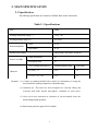
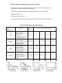
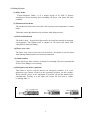
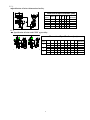
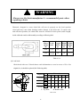
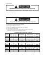
ELECTRIC CHAIN HOIST
OPERATION MANUAL
&
PARTS LIST
SERIES:
□
YSS(D)-200
□
YST(D)-200
□
YSS(D)-250
□
YST(D)-250
□
YSS(D)-300
□
YST(D)-300
□
YSS(D)-500
YST(D)-500
□
YSS(D)-750
□
□
□
YSS(D)-1000
□
CHENG DAY MACHINERY WORKS CO., LTD.
SAFETY-IMPORTANT
The use of any hoist and trolley presents some risk
of personal injury or property damage.
That risk is greatly increased if proper instructions
and warnings are not followed. Before using this
hoist, each user should become thoroughly familiar
with all warnings, instructions and recommendations
herein.
THIS SYMBOL POINTS OUT IMPORTANT SAFETY
INSTRUCTIONS WHICH IF NOT FOLLOWED
COULD ENDANGER THE PERSONAL SAFETY
AND/OR PROPERTY OF YOURSELF AND OTHERS.
READ AND FOLLOW ALL INSTRUCTIONS IN
THIS MANUAL AND ANY PROVIDED WITH THE
EQUIPMENT BEFORE ATTEMPTING TO
OPERATE YOUR "BLACK BEAR” ELECTRIC
CHAIN HOIST.
1
CONTENTS
Safety – Important … … … … … … … … … … … … … … … … … … … … … … … … … … … … … …
1
1.Foreword… … … … … … … … … … … … … … … … … … … … … … … … … … … … … … … … .
3
2.Main Specification… .… … … … … … … … … … … … … … … … … … … … … … … … … … … …
4
2.1 Specification… … … … … … … … … … … … … … … … … … … … … … … … … … … … … …
4
2.2 Mechanical Classification (Grade) and Life… … … … … … … … … … … … … … … … …
5
2.3 Safety Device… … … … … … … … … … … … … … … … … … … … … … … … … … … … …
6
2.4 Main Specification and Dimensions of Hook Suspension Type Hoist… … … … … … …
7
2.5 Optional Trolley Accessory..… … … … … … … … … … … … … … … … … … … … … … …
8
3.Safety Rules… … .… … … … … … … … … … … … … … … … … … … … … … … … … … … … …
10
4.Installation… … … … … … … … … … … … … … … … … … … … … … … … … … … … … … … …
13
4.1 Unpacking Information.… … … … … … … … … … … … … … … … … … … … … … … … …
13
4.2 Voltage… … … … ..… … … … … … … … … … … … … … … … … … … … … … … … … … …
13
4.3 Installation… … … … … … … … … … … … … … … … … … … … … … … … … … … … … …
13
5.Operation.… … … … … … … … … … … … … … … … … … … … … … … … … … … … … … … …
16
6.Maintenance and Inspection… … … … … … … … … … … … … … … … … … … … … … … … …
16
6.1 Maintenance… .… … … … … … … … … … … … … … … … … … … … … … … … … … … …
16
6.2 Inspection… … … … … … … … … … … … … … … … … … … … … … … … … … … … … … …
17
7.Troubleshooting… … … … … … … … … … … … … … … … … … … … … … … … … … … … … …
21
7.1 Wiring Diagrams… … … … … … … … … … … … … … … … … … … … … … … … … … … …
21
7.2 Troubleshooting and Remedial Action… … … … … … … … … … … … … … … … … … …
28
8.Drawings and Parts Lists..… … … … … … … … … … … … … … … … … … … … … … … … … .
29
9.Declaration Of Conformity… … … … … … … … … … … … … … … … … … … … … … … ..
57
2
1. FOREWORD
This manual contains important information to help you properly install, operate and
maintain the Black Bear electric chain hoist for maximum performance, economy and safety.
Please study its contents thoroughly before putting the electric chain hoist into operation.
By practicing correct operation, procedures and by carrying out the preventative maintenance
recommendations, you will be assured of dependable service. In order to help us to supply
correct spare parts quickly, please always specify,
(1) Hoist Model
(2) Serial Number
(3) Part Number, plus the description.
We trust that you will find this “Black Bear” electric chain hoist will give you many years
of satisfactory service.
Should you have any queries, please contact:
(Please ask for a company’s stamp from your local agent.)
3
2. MAIN SPECIFICATION
2.1 Specification
The following specifications are common to all Black Bear electric chain hoists.
Table 2-1 Specifications
Item
Detail
Working temperature range(℃)
-20 to +40
Working humidity range (%)
85 or less
Hoist
IP 42
Push button
IP 20
Protection(Option)
Electric power supply
Three Phase, 200~600V, 50/60 Hz
Single speed hoist
81
Dual Speed hoist
81
WLL (working load limit) (t)
Nominal diameter (mm)
Pitch (mm)
2T(YSS), 3T
10.0
30
2.5T,5T, 7.5T, 10T
11.2
34
Noise Level (dB)
Chain size
Remarks : (1) Contact an authorized Black Bear dealer for information on using the
hoist outside the working temperature or humidity range.
(2) Intended use: This hoist has been designed for vertically lifting and
lowering load under normal atmospheric conditions of work place.
(3) Noise levels were measured at a distance of 1m horizontally from- the
hoists during normal operation.
(4) Push button protection grade IP 65 available.
4
2.2 Mechanical Classification (Grade) and Life
Safety and life for electric chain hoists are guaranteed only when the said equipment is
operated in accordance with the prescribed grade.
Black Bear electric chain hoists have been designed for grade 1Am in the FEM
regulations (FEM 9.511).
Details are provided in Table 2-2.
Average daily operating time and total operating time are determined by load distribution.
Table 2-2 Mechanical classifications
Load Spectrum
(Load
distribution)
1
(light)
2
(medium)
3
(heavy)
Definitions
Mechanisms or parts
thereof, usually
subject to very small
loads and in
exceptional cases only
to maximum loads.
Mechanisms or parts
thereof, usually
subject to small loads
but rather often to
maximum loads.
Mechanisms or parts
thereof, usually
subject to medium
loads but frequently to
maximum loads.
Cubic
mean
value
k ≦
0.50
≦2
2-4
4-8
8-16
0.50 < k
≦ 0.63
≦1
1-2
2-4
4-8
0.63 < k
≦ 0.80
≦0.5
0.5-1
1-2
2-4
≦0.25
0.25-0.5
0.5-1
1-2
1Bm
1Am
2m
3m
Mechanisms or parts
thereof, usually
0.80 < k
4
subject
to
maximum
(very heavy)
≦ 1.00
or almost maximum
loads.
Mechanical Classifications due to DIN 15020 or
FEM 9.511
% operating time
Load spectrum 1
Average daily operating time (h)
% operating time
Load spectrum 2
% operating time
Load spectrum 3
5
% operating time
Load spectrum 4
2.3 Safety Devices
(1) Motor brake
"Electro-Magnetic Brake" is of a unique design in its field. It features
simultaneous motor braking upon switching off power even under full load
condition.
(2) Mechanical load brake
The mechanical load brake can hold a full capacity load independent of motor
brake.
This brake assures that load does not accelerate while being lowered.
(3) Hook and hook latch
The hook is drop - forged from high tensile steel and heat treated for strength
and toughness. The bottom hook is capable of 360°
swivel and fitted with
safety latch to ensure safe lifting.
(4) Phase error relay
The phase error relay circuit has been exclusively developed to prevent motor
from running when the phases are incorrectly connected.
(5) Limit Switches
Upper and lower limit switches are fitted for switching off power automatically
in case of over lifting or over lowering.
(6) Emergency stop device (optional)
This button is used to stop the hoist in an emergency situation. It is a red,
mushroom type button, located in the uppermost position on the pendant.
When pressed, power to the equipment is switched off and the button locks
automatically. Turning it to the right will release the lock and to enable
re-starting. (Illus. 1)
Illus. 1
6
2.4 Main Specification and Dimensions of Hook Suspension Type Hoist:
Capacity (ton)
Lift Height
Load Chain (mm)
Single
50HZ
YSS
Speed
60HZ
YSS
(m/min)
Dual
50HZ
YSS
Speed
60HZ
YSS
(m/min)
N.W./G.W. (kg)
MOTOR POWER (kw)
2
2.5
3
5
3 (6) etc.
φ10
7.5
10
φ10
φ11.2
6.6
5.2
4.3
2.6
1.8
2.6
7.9
6.4
5.2
3.2
2.1
3.2
6.6/2.2
5.2/1.7
4.3/1.4
2.6/0.9
1.8/0.6
2.6/0.9
7.9/2.6
6.4/2.0
5.2/1.7
3.2/1.0
2.1/0.7
3.2/1.0
φ11.2
125/155 130/160 140/170 153/183 195/230 410/470
3.7
3.7x2
50HZ
POWER SUPPLY
3 PHASE, 220V-660V,
60HZ
E.D. Rating (%)
40
Local Chain Fall Number
1
2
3
4
φI
K
φ
■ Dimension(mm)
Capacity
(ton)
Type
2
2.5
YSS-200
YSS-250
835 640 SD650 326 SD336 314
880 640 SD650 326 SD336 314
3
5
7.5
YSS-300
YSS-500
YSS-750
10
2.4.1
H
A
B
C
D
E
F
I
J
K
L
M
N
448 278 170
448 278 170
52
52
43
43
52
52
43
43
34
34
34
34
960 640 SD650 326 SD336 314
1030 640 SD650 326 SD336 314
1050 640 SD650 326 SD336 314
448 340 108
448 356 92
587 388 199
52
62
72
43
45
40
52
62
75
43
45
57
34
45
84
34
45
48
YSS-1000 1270 640 SD650 326 SD336 314
970 485 485
72
40
100
68
92
60
Low Headroom type (YST series)
Capacity
(Ton)
Dimensions (mm)
Model
H
2
2.5
3
5
YST-200
YSTD-200
YST-250
YSTD-250
YST-300
YSTD-300
YST-500
YSTD-500
7
A
B
C
D
660 640 925 423 502
676 640 925 423 502
725 640 925 423 502
765 640 925 423 502
Lift speed Trolley speed Flange
Weight
(m/min.)
(m/min.)
Width
(kg)
E(mm)
50HZ 60HZ 50HZ 60HZ
6.7
7.9
20
6.7/2.2 7.9/2.6 20/7
5.2
6.4
20
5.2/1.7 6.4/2.1 20/7
4.3
5.2
20
4.3/1.4 5.2/1.7 20/7
2.6
3.2
20
2.6/0.9 3.2/1.0 20/7
24
24/8
24
24/8
24
24/8
24
24/8
125~175
335
125~175
340
125~175
350
125~175
365
2.4.2 Standard Lifting Height and Tools
◎ Standard Lifting Height: 3 Meters With Chain Container
◎ One Tool Sets
2.5 Optional Trolley Accessory
●
Plain Trolley
A
F
B
Dimensions (mm)PT
C
G
Capacity
L
I
H
K
D1
2
3
5
7.5
10
J
●
B
C
D1 E
Flange
Width
F
G
E
(ton) Model A
PT-200
PT-300
PT-500
PT-750
PT1000
273
296
296
368
382
87 141
90 143
102 157
170 170
170 170
214 109
251 128
251 128
292 135
319 149
H
135 100-150 159
150 100-150 175
150 125-175 178
184 152-203 240
190 152-203 229
I
J
55 61
78 60
84 60
108 76
90 76
K
Min
N.W
Radius
(kg)
of Curve
L
290
379
385
440
449
98 16.7
115 26.4
115 26.7
120 70.6
140 75.7
Geared Trolley
A
F
B
C
Dimensions (mm)GT
D1
D2
Capacity
(ton)
Model A
B
C D1 D2 E
F
Flange
Width
H
G
I
J
K
L
N.W.
(kg)
Min
Radius
of
Curve
22.1
31.1
31.4
73.5
85.9
1.6m
2.0m
2.2m
1.8m
1.8m
I
H
K
L
E
G
2
3
5
7.5
10
J
●
GT-200
GT-300
GT-500
GT-750
GT-1000
273
296
296
368
382
119 141 223
122 143 234
135 157 234
191 170 280
191 170 301
214 109
251 128
251 128
292 135
319 149
135 100-150
150 100-150
150 125-175
184 152-203
190 152-203
159 55
175 78
178 84
240 108
229 90
61
60
60
76
76
300 98
362 115
368 115
428 120
431 140
Monorail Motorized Trolley
Dimensions / Specifications (mm)
B
D
C
A
G
Capacity
(ton)
Model
A
B
C
D
F
MT-200
323 567 358 209 272
MTD-200
MT-300
3
359 662 417 245 297
MTD-300
MT-500
5
389 673 422 251 320
MTD-500
MT-750
7.5
400 736 465 271 530
MTD-750
MT-1000
10
536 821 550 271 565
MTD-1000
MT-200~500 50HZ with motor of 4P
60HZ with motor of 4,6P
F
2
E
●
1.6m
2.0m
2.2m
1.8m
1.8m
Flange
width
E
G
Speed (m/min) Motor Pole N.W. Min Radius
(P) (kg) Of Curve
50HZ 60HZ (kw)
20
20/7
20
125-175
20/7
20
125-175
20/7
13
150-200
13/6.5
14
150-200
14/7
161 100-150
172
183
228.3
277.3
24,16
24/8
24,16
24/8
24,16
24/8
16
16/8
17
17/8.5
0.25
0.25/0.08
0.6
0.6/0.2
0.6
0.6/0.2
0.9
0.9/0.45
1.5
1.5/0.75
4, 6
4/12
4, 6
4/12
4, 6
4/12
6
6/12
6
6/12
45
1.5m
65
1.8m
89
2m
155
3m
218
3.5m
Motor Saddle Trolley
Dimensions / Specifications (mm)
Capacity
(ton)
2
3
5
7.5
10
Model
MST-200
MSTD-200
MST-300
MSTD-300
MST-500
MSTD-500
MST-750
MSTD-750
MST-1000
MSTD-1000
Speed (m/min)
50HZ 60HZ
20
20/6.7
18
18/9
18
18/9
19
19/6.3
21
21/7
19
19/6.3
22
22/11
22
22/11
23
23/7.7
20
20/6.7
A
B
C
D
E
120 580 700 40 147 136
150 650 850 45 178 164
150 650 850 50 178 164
160 800 1000 50 189 225
215 900 1200 50 246 318
MST-200, 1000 -50HZ with pinion of M3.5×15T,
-60HZ with pinion of M3.5×12T,
MST-300,MST-500 60HZ/50HZ with pinion of M3.5×20T
MST-750 60HZ/50HZ with pinion of M3.5×15T
8
H
Motor
(kw)
0.25
0.28/0.08
0.6
0.6/0.3
0.6
0.6/0.3
0.9
0.9/0.3
0.9-2pcs
0.9/0.3-2pcs
Pole N.W.
(P) (kg)
4
94
4/12
6
182
6/12
6
182
6/12
4
306
4/12
4
504
4/12
2.5.1:
●Specification of hoist with motorized trolley.
Dimensions/Specifications (mm)
Capacity
Model
(ton)
H
A
B
C
Adjustable
Span(mm)
D
2
MT-200
995 323 567 358 209
100-150
3
MT-300
1120 359 662 417 245
125-175
5
MT-500
1200 389 673 422 251
125-175
7.5
MT-750
1300 400 736 465 271
150-200
10
MT-1000 1415 536 821 550 271
150-200
2.5.2:
● Specification of hoist with GT/PT type trolley.
Dimensions/Specifications (mm)
Capacity
(ton)
2
3
5
9
Model
H
A
B
C
D1
D2
214 277.5 3279
GT-200 983
273 136.5 141
223
PT-200 983
273
141
214
GT-300 1138 296 139.5 143
234
PT-300 1138 296
143
251
GT-500 1210 296 152.5 157
234
PT-500 1210 296
251
87
90
102
157
-
E
228
G
-
251 282.5 3353
-
233
-
251 309.5 3356
-
259
-
Adjustable
Span(mm)
100-150
100-150
100-150
100-150
125-175
125-175
3. SAFETY RULES
DANGER
The hoist herein is not designed for, and should not be used for, lifting, supporting,
or transporting personnel. Any modifications to upgrade , re-rate, or otherwise
alter the hoist equipment must be authorized by either the original manufacturer or
a qualified professional engineer.
(1) Only the trained personnel are allowed to operate the hoist.
DANGER
(2)
Do not use the hoist in explosive atmosphere.
(3) Prior to each lifting operation, it is essential to make sure that:
(a) the correct lifting sling is being used.
(b) the lifting sling is located in the hook as shown below (Illus. 2) and that a safety latch has
been fitted.
Illus. 2
(c) the object to be hoisted is well secured for direct lifting (a proper lifting frame or
apparatus is strongly recommended for direct lifting.)
10
(4)Firm and steady button operation is required, never push the button switch
intermittently.
(5) Always avoid excessive inching operation.
(6) Always make sure the hoist motor completely stops before reversing.
(7) Always leave the pendant button switch cable and bottom hook load chain
vertically static after completion of operation, never leave them at any position,
which may allow them swing or slip.
(8) Sling must be applied to load evenly and centrally to ensure correct balance.
Never lift any object which is insecure or out of balance.
(9) Never use hoist to end or side pull a load. (Illus. 3)
(10) Never wrap around and hook back the load chain as a sling to lift a load. (Illus. 4)
Illus. 3
(11)
Illus. 4
WARNING
Do not use the hoist chain as a welding electrode.
11
DANGER
(12)
Never stand under a raised load (Illus. 5)
Illus. 5
(13) Lifting must always be personally attended, never leave a raised load unattended.
(14) Over-capacity-load lifting is hazardous and should not be undertaken.
(15) Never lift a load when the load chain is twisted.
(16) Regularly inspect and check the condition of load chain. Do not operate with damaged chain.
12
4. INSTALLATION
4.1 Unpacking Information
After removing the hoist from its packing box, carefully inspect the external condition of
the electrical cables, contactor, gearbox and motor casing for damage.
Check and ensure that these items are present.
Each hoist is supplied as standard with the following accessories:
1. Chain bucket
1 set
2.Power cable
3 meters
3.Push button control switch
1 piece
Table 4-1
4.2 Voltage
CAUTION
If power supply deviates from standard by more than ±10% abnormal operation or
damage to the motor may result. It is imperative to ensure correct voltage supply before
commencing operation.
4.3 Installation
WARNING
Connection to power supply before installation procedures having been completed is
strictly prohibited.
13
(1)
Prior to installation check and ensure that the top hook assembly is securely attached
to the hoist by means of the connecting pin (page 35, item 13)
NOTE: If the hoist is to be suspended from an electric trolley, assembly may be eased
by firstly removing the top hook, just attaching hoist top hook to the trolley
load plate.
(2)
Assemble chain bucket.
Illus. 6
(3) Connect power supply to hoist and operate the push button switch. This operation must
be carried out by a trained person .
Illus. 7
14
(4) Operation Test
(A) Firmly push
switch button to lower load chain until the limit spring
touches the limit switch. Power should be cut off automatically.
(B) Firmly push
switch button to check the collection of load chain into
chain bucket.
(C) Check the emergency stop device function (if fitted):
While holding down either
or
button on the push button switch,
push the emergency stop button. Check that the hook stops when the
emergency stop button is pushed. Also, check the hoist does not move in
response to the push button switch. Finally, check that the emergency stop
device pops out when turned to the right and that operation can be resumed
thereafter. If the equipment fails to pass another above checks, check the
wiring and automatic locking function of the emergency stop device.
(D) Check load chain lubrication (It has been lubricated at our works, but the
lubricant may dry out during transportation). Any readily available lubricant
is recommended. It is further advisable to keep a small amount of lubricant in
chain bucket to allow chain in oil bath.
(E) Check chain position. Weld joints on links must face the same direction (Illus.
8), correct chain operation can only be achieved when all joints are vertically
in line.
CAUTION
The bottom hook on multi-fall hoist must never be rotated as shown below
(Illus. 9).
Illus. 8
Illus. 9
15
5. OPERATION
After running test and checks have been completed, the hoist will be ready for normal operation.
WARNING
Since dealing with heavy loads may involve unexpected danger, all of the
"SAFETY RULES" (Ref 3.) must be followed and the operator must be aware
of the following points while using the hoist.
(1) The operator must have a clear and unobstructed view of the entire working area before
operating the hoist.
(2) The operator must check that the entire working area is safe and secure before operating
the hoist.
(3) When using the hoist with a motorized trolley, the operator must take care to prevent
excessive load swinging by sympathetic use of the trolley controls.
6. MAINTENANCE AND INSPECTION
DANGER
Do not perform maintenance on the hoist while it is carrying a load except monthly
checking for the brake or limit switch.
DANGER
Before performing maintenance do not forget to affix tags to the power source and
the push button switch reading: “DANGER”, “EQUIPMENT BEING
REPAIRED”.
6.1 Maintenance
(1) Check the level of gear box lubricant after first 500 hours of operation, thereafter every 3 months and
lubricant accordingly.
NOTE: WE RECOMMEND USING A LUBRICANT OIL EQUIVALENT TO ISO VG460.
(2) Always keep the hoist unit dry and never misuse it in a manner likely to reduce its durability.
16
(3) When it is necessary to keep the unit outdoors, a protective covering should be fitted.
6.2 Inspection
(1) Daily inspection: Before starting daily operation, check the following
(a) Correct power supply.
(b) "Up", "Down" and "Emergency stop" (where fitted) test runs under no load.
(c) Correct motor performance.
(d) No abnormal or excessive noise.
(e) No malfunction of the bottom hook safety latch.
(f) Proper function of moving/turning parts, limit switches and brake.
(g) Well lubricated load chain.
(2) Monthly inspection
(a) Load chain:
Chain Wearing Test
Load Spectrum
Using times
Cubic mean
Value
Non-lubricated
1 (Light)
50%
75000
2 (Medium)
63%
55500
3 (Heavy)
85%
30000
4 (Vary heavy)
100%
15000
Above testing data under lifting height 1M
17
Lubricated
175000
129500
70000
35000
WARNING
Always use the hoist manufacture's recommended parts when
repairing a hoist.
Distorted, elongated or worn chain link will not sit properly on the load sprocket
wheel and may cause chain breakage and/or damage to the hoist unit. To ensure safe
and efficient operation, the chain links must be checked for their pitch (inside length),
inside width and outside width monthly according to following table.
DiaMeter
(m/m)
(d)
Inside Inside Outside
Length Width Width
(m/m) (m/m) (m/m)
(p)
(a)
(b)
Load
(ton)
10.0
2,3T
30
12.5
33.2
11.2
2.5,5
7.5,10T
34
14
37.2
Table 6-2-a
(b) Load hook:
Check hook with care. If hook shows crack deformation or wear in excess of 5% of its
original size, it should be replaced (Ref. following table)
g
2,3 Ton
a
e
5 Ton
7.5 Ton
c
b
Capacity
10 Ton
d
a
Dimensions
b
c
d
e
g
55
34
48
34
52
43
67
45
60
45
62
45
75
48
68
48
75
57
100
65
95
60
100
68
T
B
T
B
T
B
B
B
T: Top hook
B: Bottom hook
Table 6-2-b
18
(c) Limit Switches:
A qualified electrician should perform this inspection.
Check correct operation of the limit switches. Clean thoroughly and apply a thin lubrication
to ensure correct operation.
(3) Annual inspection
Your dealer should be asked to perform this inspection.
(a) Check gearing for any excessive wear or damage.
(b) Replace gearbox lubricant completely.
(c) Check brake lining and ratchet pawl for any wear or damage.
(d) Check operation of pawl spring.
(e) After reassembly of above check, lifting a load several times to ensure good
performance of the hoist before starting duty operation.
φ190 BUCKET SPECIFICATIONS
Bucket
No.
Chain
Size
Chain length (M)
Bucket Size (mm)
Material
ψ10
ψ10
< 8.8
8.8 - 20.8
190 × 190 × 310L
190 × 190 × 440L
200783
6
7
8
21 - 30.8
200784
8-1
ψ10
ψ10
190 × 190 × 560L
340 × 210 × 495 × t2
canvas
canvas
canvas
steel
200785
9
ψ10
400 × 210 × 605 × t2
steel
200786
10
ψ10
400 × 210 × 695 × t2
steel
200781
6
ψ11.2
39 - 47.8 M
< 8.8
190 × 190 × 310L
canvas
200782
200783
7
8
ψ11.2
ψ11.2
8.8 - 18.8
19 - 27.8
190 × 190 × 440L
190 × 190 × 560L
canvas
canvas
200784
8-1
ψ11.2
< 19M
340 × 210 × 495 × t2
steel
200785
9
ψ11.2
19.8 - 31 M
400 × 210 × 605 × t2
steel
200786
10
ψ11.2
32 - 40.8 M
400 × 210 × 695 × t2
steel
Key No.
200781
200782
21- 26.8 M
27 - 38.8 M
19
Chain Gauge – Wear and Stretch Measuring
(1) The chain gauge is useful and convenience for measuring.
(2) Please use a chain gauge to measure the chain pitch and diameter, such as illustrations (1)
and (2).
(3) Every chain ring must be measured , and the chain must be replaced when one of chain
rings is wear or stretch.
(4) It will be a cutting-out possibility if you use a chain fall either wear or stretch during
operation.
(5) Do not replace a chain fall by yourself and do please contact specific either service
centers or contractors to help you out.
(6) The chain fall must be replaced whole instead of a partial part.
(7) The load sheave, regulator, and chain compressing wheel must be replaced the same time as
you do a second time replacement.
Remark
(1) Chain must be perfect condition without any defects and attachments.
OK
OK
OK
NO
Illustration (1)
Chain pitch measure
Illustration (2)
Diameter measure
20
NO
7. TROUBLESHOOTING
7.1 Wiring Diagrams
(1) C10011: dual voltage 220V/380V +220V/440V +230V/460V motor lead wiring
diagram.----------------------------------------------------------------------------------22
(2) A50143: single speed wiring diagram 230V/110V(with Emergency Stop).-----22
(3) A50005: single speed wiring diagram 380V/48V-----------------------------------23
(4) A50059: single speed wiring diagram 380V/48V with electronic over load
limit----------------------------------------------------------------------------------------23
(5) A60003: dual speed wiring diagram 380V/48V ------------------------------------24
(6) A60051: dual speed wiring diagram 380V/48Vwith electronic over load
limit.---------------------------------------------------------------------------------------24
(7) A50131: 10Tons, single speed wiring diagram 380V/48V.-------------------------25
(8) A70008: single speed wiring diagram 230V/110V + 4P ---------------------------26
(9) A70007: UP/DN dual speed wiring diagram 460V/110V +4P---------------------27
The above models are available in the following specification:
(a) 3-Phase
(b) 50 or 60 Hertz
(c) Single and dual voltage
Voltage
Hertz
50 Hz
60 Hz
Dual Voltage
Single Voltage
220V/380V
220V/440V
230V/460V
220
to
600
Table 7-1
21
22
23
24
25
26
27
7.2 Troubleshooting and Remedial action
SITUATION
Hoist will not
operate
CAUSE
REMEDY
(1) Phase error relay operated
due to incorrect phase
connections
(2) Blown power fuse or
tripped power circuit
breaker
(3) Blown control circuit fuse
(4) Broken/disconnected power
or control circuit wire
(5) Low supply voltage
(6) Motor hums but does not
rotate
(7) Emergency stop button
release pushed (if fitted)
(8) Faulty contactor
Reverse any two phase connections
Check supply requirements and refuse/reset breaker
to meet requirements
Check fuse for correct rating and replace
Locate and repair/reconnect
Check if 10% reduction in voltage, have mains
supply checked
Check phases to motor - insulate and repair
Check the cause as necessary
Operate manually if hoist runs then control
circuit/coil is faulty - locate fault and repair. If hoist
does not run then check main supply. If input
supply is correct but there is a faulty output supply
then replace the contactor
Hoist will not stop
Welded contacts in contactor
Replace contactor
Brake slips
Abrasion of motor brake
Replace
Abnormal sound.
on load chain/
chain sprocket
(1) Chain dry
(2) Worn chain sprocket
Lubricate
Replace load chain and chain sprocket
Electric shock
(1) Poor earth connection
(2) Accumulated foreign matter/
moisture on electrical parts
Provide correct earth connection
Remove foreign matter/dry electrical parts
Oil leak
(1) No oil plug
(2) Loose fitting of oil plug
(3) No plug packing
(4) Worn or deteriorated oil
packing
Attach the normal oil plug
Fasten the plug tightly
Attach normal packing
Attach the new packing
28
8. Drawings and parts list
(1). VIII- 1 Motor Assembly & Housing Drawing --------------------------------------------- 30
(2). VIII- 1 Motor Assembly & Housing B.O.M ----------------------------------------------- 31
(3). VIII- 2A Hook Assembly 2,2.5,3,5 Tons Drawing ------------------------------------------ 34
(4). VIII- 2A Hook Assembly 2,2.5,3,5 Tons B.O.M ------------------------------------------ 35
(5). VIII- 2B Hook Assembly 7.5 Tons Drawing -------------------------------------------------37
(6). VIII- 2B Hook Assembly 7.5 Tons B.O.M ------------------------------------------ 38
(7). VIII- 2C Hook Assembly 10 Tons Drawing ------------------------------------------ 40
(8). VIII- 2C Hook Assembly 10 Tons B.O.M ------------------------------------------ 41
(9). VIII- 3 Reducing Gear Box Drawing ---------------------------------------------------43
(10). VIII- 3 Reducing Gear Box B.O.M -------------------------------------------- 44
(11). VIII- 4 Load Chain Section Drawing -------------------------------------------45
(12). VIII-4 Load Chain Section B.O.M ----------------------------------------------46
( 1 3 ) . V I I I- 5 Electric Parts Drawing (Standard Parts)- - - - - - - - - - - - - - - - - - - - - - - - - - - - - - - - - -4 7
( 1 4 ) . V I I I- 5 E l e c t r i c P a r t s B . O . M ( S t a n d a r d P a r t s ) - - - - - - - - - - - - - - - - - - - - - - - - - - - - - - - - - - 4 8
(15). VIII-5- 1 Electric Parts Drawing(USA)-----------------------------------------------------------50
(16). VIII- 5- 1 Electric Parts B.O.M(USA) ------------------------------------------------------------51
(17). VIII- 6 Low Headroom Model’s Drawing -----------------------------------------------53
(18). VIII- 6 Low Headroom Model’s B.O.M -------------------------------------------------54
29
VIII-1 MOTOR ASS'Y & HOUSING
1
2
3
4
5
16
6
13
17
7
14
18
19
8
9
11
10
15
20
21
10
11
14
12
3
4
5
7
22
23
DU
AL
SP
EE
D
8
25
19
26
24
27
12
28
29
38
21
30
21
31
39
32
33
34
35
36
40
37
2
41
42
43
44
39
45
46
39
52
47
48
53
49
54
2
50
55
51
14
15
30
EX190E1
VIII – 1 MOTOR ASSEMBLY & HOUSING
S : SINGLE SPEED D : DUAL SPEED
Q’TY REQ’D EACH UNIT
KEY
NO.
1
2
3
4
5
6
7
8
9
10
11
12
PARTS
CODE
400014
400095
100424
100425
100490
100495
100395
100409
100406
400237
400239
100414
100498
400193
400141
400200
100325
100324
2T
DESCRIPTION
Hex. Recess Bolt <M8×1.25×30L>
Spring Washer <M8>
Motor End Cover
3T
S
D
S
11
4
15 11
1
1
D
1
Spacer Ring
Brake Gap Adjuster
Brake Drum
1
1
4
15
16
17
18
400006
400264
400220
400221
Hex. Recess Bolt <M6×1.0×16L>
Rubber Cap
Castle Nut <AN06>
External Teeth Washer <AW06>
4
1
1
1
19
20
21
100430
400023
400097
Bearing Stop Ring
Hex. Recess Bolt <M12×1.75×35L>
Spring Washer <M12>
2
4
22
23
24
25
100363
100365
100410
400218
Motor Shaft Spacer
Motor Retaining Ring
Cone Spring
Eye Bolt <M10×1.5>
2
1
1
400585 Blot <M8×1.25×16L>
A
27
Motor Stator Ass ’y
B
#27Ref. Page33
1
1
1
1
1
1
1
6
1
12
2
1
1
1
1
1
1
1
2
2
2
6
1
1
2
2
1
1
1
2
2
1
1
2
2
1
1
1
D
2
1
1
1
2
2
1
2
1
1
1
1
2
3
15
3
15
3
15
3
15
6
30
12
4
4
1
1
1
12
2
4
4
4
1
1
1
12
2
4
12
4
4
1
1
1
12
2
4
12
2
1
1
8
8
2
2
2
4
8
12
2
1
1
24
24
2
1
1
4
2
2
1
1
1
1
2
2
2
2
2
4
1
1
1
31
1
6
12
26
1
1
1
Hex. Recess Bolt <M6×1.0×20L>
Spring Washer <M6>
8
22 30
1
1
1
1
400007
400094
4
15
1
1
1
13
14
4
15 11
1
1
Motor Rotor
4
15 11
1
6
Magnet Producer
Magnet Coil Ass ’y
Retaining Ring <S-30>
Bearing <6206 ZZ>
Retaining Ring <R-62>
S
1
1
1
10T
D
1
Revolving Brake Disc
Brake Lining
D
7.5T
S
1
1
S
1
1
Brake Spring
2.5, 5T
1
1
1
1
2
1
2
VIII – 1 MOTOR ASSEMBLY & HOUSING
S : SINGLE SPEED D : DUAL SPEED
Q’TY REQ’D EACH UNIT
KEY
NO.
PARTS
CODE
DESCRIPTION
2T
S
3T
D
S
2.5, 5T
D
S
D
7.5T
S
D
10T
S
D
28
29
30
31
402507
400084
100339
200308
Gasket 7#
Nut <M12×1.75>
Motor End Plate
Connecting Screws Sleeve
1
4
1
4
1
4
1
4
1
4
1
4
1
4
1
4
2
8
2
8
32
33
34
35
36
37
38
39
40
200698
404324
402506
200066
400032
402510
400021
400215
200245
1
1
1
1
4
1
4
4
1
1
1
1
1
4
1
4
4
1
1
1
1
1
4
1
4
4
1
1
1
1
1
4
1
4
4
1
2
2
2
2
8
2
8
8
2
41
400024
6
6
6
6
12
42
43
44
45
402511
400219
400227
400631
Load Sheave Housing
O-Ring <G-90>
Gasket 6#
Gear End Plate
Hex. Bolt <M12×1.75×120L>
Gasket 10#
Hex. Recess Bolt <M12×1.25×25L>
Spring Pin <ø12×14L>
Gear Box A
Oiltight Hex. Recess Bolt
<M8×1.25×25L>
Gasket 11#
Eye Bolt <M16×2>
Gasket Ring
Wing Nut <M4×0.7>
1
1
1
1
1
1
1
1
1
1
1
1
1
1
1
1
2
2
2
2
46
47
48
49
400050
400212
400267
402522
Cross Headed Screw <M4×0.7×10L>
Spring Pin <ø5×16L>
Rubber Band
Gasket 22#
1
1
1
1
1
1
1
1
1
1
1
1
1
1
1
1
2
2
2
2
50
51
52
300347
400225
Electric Housing
Name Plate
O-Ring <ø8×ø12×2>
1
1
1
1
1
1
1
1
1
1
1
1
2
2
2
53
54
55
400600
200246
400460
Lubricant Drain Bolt
Gear Box B
Hex. Recess Bolt <M8×1.25×65L>
1
1
5
1
1
5
1
1
5
1
1
5
2
2
10
32
VIII – 1 MOTOR ASSEMBLY & HOUSING
S : SINGLE SPEED D : DUAL SPEED
KEY
NO.
PARTS
CODE
A
27
B
132701
132702
132707
132708
132706
132711
132712
132713
132714
132801
132802
132803
132804
132805
132811
132812
132813
132814
φ - HZ - V
DESCRIPTION
3φ 60HZ
Motor Stator Ass ‘y (S)
3φ 50HZ
3φ 60HZ
Motor Stator Ass ’y (D)
3φ 50HZ
33
220 / 380 V
220 / 440 V
230 /460V
400 V
600 V
220 / 380 V
400 V
415 V
525 V
220 V
230 V
380 V
460 V
600 V
220 V
380 V
415 V
525 V
HOOK ASSEMBLY (2, 2.5, 3, 5T)
1
5
1
2
6
2
7
3
4
2T&2.5T
8
9
10
3T&5T
5
11
12
13
14
14
17
15
23
16
24
17
25
18
26
27
19
28
20
29
21
19
22
21
2
20
2T&2.5T
2
22
3T&5T
34
VIII – 2A HOOK ASSEMBLY(2, 2.5, 3, 5T)
S : SINGLE SPEED D : DUAL SPEED
Q’TY REQ’D EACH UNIT
KEY
NO.
PARTS
CODE
2T
DESCRIPTION
S
1
2
3
4
200012
200013
1
S
2
2
S
D
1
2
2
1
1
200177 Chain Connecting Pin <ø19×70L>
1
200178 Chain Connecting Pin <ø19×72L>
7
5T
D
200095 Top Hook Pin <ø34×134L>
6
10
D
200094 Top Hook Pin <ø25×107L>
400603 Cotter Pin <3/32”×1”L>
9
S
3T
1
400301 Safety Latch Ass’y
5
8
D
1
Top Hook
2.5T
1
1
1
2
2
400091 Lock Nut <M12×1.75>
1
1
400097 Spring Washer <M12>
1
1
400085 Nut <M16×1.5>
1
400086 Nut <M20×2.0>
1
400099 Spring Washer <M20>
1
200155
1
Hook Bracket
200156
1
11
400085 Nut <M16×1.5>
1
1
1
1
12
400098 Spring Washer <M16>
1
1
1
1
13
200165 Rigid Hook Connecting Pin
1
1
1
1
200759
1
14
200026
200025
1
Bottom Hook Ass ‘y
1
200027
15
16
1
400088 Lock Nut <M8×1.25>
4
400089 Lock Nut <M10×1.5>
4
400095 Spring Washer <M8>
4
400096 Spring Washer <M10>
4
200099
17
200126
200100
1
1
Bottom Hook Housing
1
200101
1
35
VIII – 2A HOOK ASSEMBLY(2, 2.5, 3, 5T)
S : SINGLE SPEED D : DUAL SPEED
Q’TY REQ’D EACH UNIT
KEY
NO.
PARTS
CODE
DESCRIPTION
2T
S
400015 Hex. Recess Bolt <M8×1.25×40L>
2.5T
D
S
D
3T
S
5T
D
S
D
4
18
400018 Hex. Recess Bolt <M10×1.5×40L>
200133
19
4
1
1
1
Bottom Hook Retaining Ring
200134
1
400159 Thrust Bearing <51106>
1
1
1
20
400160 Thrust Bearing <51207>
1
200129
21
2
2
2
Bottom Hook Half Spacer
200130
2
200003
22
1
1
1
Bottom Hook
200004
1
408052 Needle Bearing <TA 3020 Z>
2
23
400174 Needle Bearing <TA 4025 Z>
2
200170 Bottom Hook Idle Wheel <ø40×42L>
1
24
200111 Bottom Hook Idle Wheel <ø50×51L>
200813 Bottom Hook Idle Wheel Axle <ø30×71L>
1
1
25
200116 Bottom Hook Idle Wheel Axle <ø40×78L>
26
1
400212 Spring Pin <ø5×16L>
1
400018 Hex. Recess Bolt <M10×1.5×40L>
3
1
27
400019 Hex. Recess Bolt <M10×1.5×45L>
3
28
400089 Lock Nut <M10×1.5>
3
3
29
400096 Spring Washer <M10>
3
3
36
HOOK ASSEMBLY (7.5T)
1
2
3
4
5
6
7
8
9
10
11
12
13
14
15
19
20
16
21
17
22
18
23
24
25
26
9
27
28
29
30
31
32
33
34
10
11
7
37
38
35
36
4
39
40
45
41
42
43
44
46
37
VIII – 2B HOOK ASSEMBLY (7.5 T)
S : SINGLE SPEED D : DUAL SPEED
Q’TY REQ’D EACH UNIT
KEY
NO.
PARTS
CODE
DESCRIPTION
7.5T
S
D
1
200162
Side Plate
2
2
200754
Suspended Frame Ass’y
1
3
200119
Idle Wheel’s Axle <ø40×83L>
1
4
400212
Spring Pin <ø5×16L>
2
5
200148
Stay Bolt <ø25×124L>
3
6
200125
Idle Wheel’s Inner Sleeve <ø49.5×ø40.5×5.5L>
1
7
400174
Needle Bearing <TA 4025Z>
4
8
200113
Idle Wheel <ø50×56L>
1
9
400287
Rubber Chain Presser
6
10
400099
Spring Washer <M20>
12
11
400086
Nut <M20×2>
12
12
200166
Side Plates Connecting Pin <ø25×97>
2
13
200311
Rigid Hook <t45×140×197L>
1
14
200315
Chain Guide(B)
1
15
200174
Rigid Hook Spacer Plate <ø26.5 P44 t6×50×92L>
2
16
200636
Connecting Pin’s Stopper <ø8.5 P28 t6.0×25×50L>
1
17
400095
Spring Washer <M8>
4
18
400012
Hex. Recess Bolt <M8×1.25×20L>
2
19
400603
Cotter Pin <3/32”×1”L>
1
20
400085
Nut <M16×1.5>
1
21
400098
Spring Washer <M16>
1
22
400089
Lock Nut <M10×1.5>
1
23
400029
Hex. Recess Bolt <M10×1.5×120L>
1
24
200165
Rigid Hook Connecting Pin <ø25×138L>
1
38
VIII – 2B HOOK ASSEMBLY (7.5 T)
S : SINGLE SPEED D : DUAL SPEED
Q’TY REQ’D EACH UNIT
KEY
NO.
PARTS
CODE
DESCRIPTION
7.5T
S
D
25
200762
Bottom Hook Ass’y
1
26
200145
Stay Bolt Sleeve <ø32×ø27×13L>
2
27
200316
Chain Guide(C)
1
28
400091
Lock Nut <M12×1.75>
1
29
200187
Chain Limiter’s Pin <ø32×108L>
1
30
400097
Spring Washer <M12>
1
31
200185
Chain’s Limiter <t55×53×116L Pø32>
1
32
200186
Chain’s Limiter Sleeve <ø40×ø33×12L>
2
33
200179
Chain’s Connect Pin To Limiter <ø19×82L>
1
34
200105
Bottom Hook Side Plate <ø11.2>
2
35
200112
Bottom Hook Idle Wheel <ø50×82L>
1
36
200117
Idle Wheel Axle <ø40×108L>
1
37
200122
Idle Wheel Inner Sleeve <ø49.5×ø40.5×31L>
1
38
200314
Chain Guide(A)
1
39
200143
Side Plate Stay Bolt <ø25×149L >
3
40
400644
Nut <1 3/4”×5UNC>
1
41
400162
Thrust Bearing <51209>
2
42
200135
Bearing Housing
1
43
200078
Forged Hook
1
44
400302
Safety Latch Ass’y
1
45
400214
Spring Pin <ø8×70L>
1
46
200765
Bottom Hook
1
39
HOOK ASSEMBLY (10T)
1
2
3
4
5
6
7
8
9
12
10
11
13
14
20
21
15
22
16
23
17
24
25
18
26
19
4
27
6
28
29
12
30
13
31
10
32
33
34
35
39
36
37
38
40
40
VIII – 2C HOOK ASSEMBLY(10T)
S : SINGLE SPEED D : DUAL SPEED
Q’TY REQ’D EACH UNIT
KEY
NO.
PARTS
CODE
DESCRIPTION
10T
S
D
1
200755
Top Hook Ass’y
1
2
200312
Side Plate Connector <t45×140×223L>
2
3
200174
Side Plate Connector Spacer<ø26.5 P44 t6×50×92L>
4
4
400212
Spring Pin <ø5×16L>
3
5
200149
Side Plate Stay Bolt <ø25×139L>
4
6
400287
Rubber Chain Guide Wheel
8
7
200163
Side Plate
2
8
200120
Idle Wheel Axle <ø40×92L>
1
9
200125
Idle Wheel Inner Sleeve <ø49.5×ø40.5×5.5L >
1
10
400174
Needle Bearing <TA 4025Z>
6
11
200113
Idle Wheel <ø50×56L >
1
12
400099
Spring Washer <M20>
20
13
400086
Nut <M20×2.0>
20
14
200167
Side Plate Connecting Pin <ø25.5×10⁷L >
4
15
400012
Hex. Recess Bolt <M8×1.25×20L>
4
16
400095
Spring Washer <M8>
4
17
200636
Connecting Pin Stopper Plate <ø8.5 P28 t6×25×50L >
2
18
400029
Hex. Bolt <M10×1.5×120L>
2
19
200165
Rigid Hook Connecting Pin <ø25×138L>
2
20
400603
Cotter Pin <3/32”×1”L>
2
21
400085
Nut <M16×1.5>
2
22
400098
Spring Washer <M16>
2
23
400089
Lock Nut< <M10×1.5>
2
41
VIII – 2C HOOK ASSEMBLY(10T)
S : SINGLE SPEED
D : DUAL SPEED
Q’TY REQ’D EACH UNIT
KEY
NO.
PARTS
CODE
DESCRIPTION
10T
S
D
24
200763
Bottom Hook Ass’y
1
25
200106
Bottom Hook Side Plate
2
26
200316
Chain Guide(C)
2
27
200144
Bottom Hook Stay Bolt <ø25×169L>
6
28
200145
Stay Bolt Spacer Sleeve <ø32×ø27×13L>
4
29
200314
Chain Guide(A)
2
30
200118
Bottom Hook Idle Wheel Axle <ø40×123L>
2
31
200122
Idle Wheel Inner Sleeve <ø49.5×40.5×31L>
2
32
200112
Bottom Hook Idle Wheel
2
33
400644
Nut <1 3/4”×5UNC>
1
34
400163
Thrust Bearing <51309>
1
35
200301
Thrust Bearing Protecting Ring <ø88×ø84×12L>
1
36
200136
Forged Hook Bearing Housing <ø62×100×122L>
1
37
200092
Forged Hook
1
38
400303
Safety Latch Ass’y
1
39
400214
Spring Pin <ø8×70L>
1
40
200766
Forged Hook Ass’y
1
42
VIII-3 REDUCING GEAR BOX
1
2
3
4
5
6
7
8
9
13
10
11
12
14
15
16
17
21
18
19
22
20
23
EX190E5
43
VIII – 3 REDUCING GEAR BOX ASSEMBLY
S : SINGLE SPEED D : DUAL SPEED
Q’TY REQ’D EACH UNIT
KEY
NO.
PARTS
CODE
DESCRIPTION
2T
S
1
2
3
4
5
6
7
8
9
10
11
12
13
14
15
16
17
18
19
20
400140
400201
400797
200695
400183
200198
200199
400185
407754
200286
Load Sheave
D
S
2.5, 5T
D
1
1
1
1
1
1
1
1
1
1
1
1
S
D
7.5T
S
D
10T
S
D
1
1
1
1
1
1
1
1
1
1
2
2
2
2
2
1
1
1
1
2
2
2
2
Oil Seal <ø58×ø80×12>
Bearing <6010>
Ratchet Pawl Shaft
1
1
1
1
1
1
1
1
1
1
400241
200288
400190
200699
407772
200733
200734
200735
Ratchet Spring
Ratchet Pawl
Retaining Ring <S-16>
Compress Retaining Sleeve
Bearing <6405>
1
1
1
1
1
1
1
1
1
1
1
1
1
1
1
1
1
1
1
1
1
2
2
2
2
2
1
1
2
200741
200665
200274
200277
407746
Ratchet Wheel Ass’y
2nd Gear
Half Spacer
Bearing Spacer
Bearing <6304>
1
1
2
1
1
1
1
2
1
1
2
2
4
2
2
1
1
2
2
1
2
22
200266
200265
200267
400197
23
407765
21
Bearing <6009ZZ>
Retaining Ring <R-75>
Bearing <6210Z>
Front Motor Axle Ass’y
Oil Seal <ø25×ø40×8>
3T
3rd Gear Ass’y
1
1
1
2
1
1
1
1
2
1
1
1
th
4 Gear
1
Retaining Ring <S-50>
1
1
1
1
Bearing <6303>
1
1
1
44
LOAD CHAIN SECTION
1
3
4
5
6
2
7
8
9
10
11
12
20
13
14
15
16
17
18
8
19
45
III – 4 LOAD CHAIN SECTION ASSEMBLY
S : SINGLE SPEED D : DUAL SPEED
Q’TY REQ’D EACH UNIT
KEY PARTS
NO. CODE
DESCRIPTION
2T
S
3T
D S
2.5T
D S
5T
D S
D
7.5T
S
10T
D S
D
1
400089 Lock Nut <M10×1.5>
2
2
2
2
2
4
2
400029 Hex. Bolt <M10×1.5×120L>
2
2
2
2
2
4
3
200203 Chain Regulating Plate <t20×50×160L>
1
1
1
1
1
2
4
400005 Hex. Recess Bolt <M6×1.0×12L>
2
2
2
2
2
4
5
400273 Compressing Wheel Axle <M8×55L>
1
1
1
1
1
2
200194 Chain Regulator <ø10>
1
1
1
1
1
2
1
1
1
2
6
200195 Chain Regulator <ø11.2>
200191 Chain Regulating Wheel <ø10 ø39×25L>
1
1
7
200192 Chain Regulating Wheel <ø11.2 ø40×28L>
8
400095 Spring Washer <M8>
6
6
6
6
6
12
9
400013 Hex. Recess Bolt <M8×1.25×25L>
4
4
4
4
4
8
10
200207 Chain Guide Ass’y
1
1
1
1
1
2
11
200223 Bucket Arm(B) <t3.0×50×180L>
1
1
1
1
1
2
12
200222 Bucket Arm(A) <t3.0×50×260L>
1
1
1
1
1
2
13
400087 Lock Nut <M6×1.0>
6
6
6
6
6
12
14
200218 Chain Bucket
1
1
1
1
1
2
15
400055 Cross Headed Screw <M6×1.0×12L>
6
6
6
6
6
12
400233 Limit Spring <ø10>
2
3
2
3
3
4
3M
3M
3M
3M
2
4
4
4
16
400234 Limit Spring <ø11.2>
400543 Load Chain <ø10>
3M
3M
17
400544 Load Chain <ø11.2>
200201 Chain Stopper <ø10>
2
4
18
200202 Chain Stopper <ø11.2>
19
400014 Hex. Recess Bolt <M8×1.25×30L>
2
2
2
2
2
4
20
200781 Chain Bucket 6#
1
1
1
1
1
2
No.20 Depends on the chain length that request by customers.
(Parts No. Please refer to page19) .
46
VIII-5 ELECTRIC PARTS (Stansard Parts)
12
13
27
25
24
12
5
26
31
23
11
12
4
13
3
2
28
1
20
32
DUAL SPEED
6
3
14
7
8
9
15
10
11
16
12
13
3
19
2
12
13
21
20
17
22
12
26
13
27
25
24
12
23
11
29
12
12
23
13
28
20
Optional
18
30 Optional
EX190E7
47
VIII – 5 ELECTRIC ASSEMBLY(Standard Parts)
S : SINGLE SPEED D : DUAL SPEED
Q’TY REQ’D EACH UNIT
KEY
NO.
PARTS
CODE
DESCRIPTION
2T
S
3T
D
S
1
2.5, 5T
D
S
1
D
7.5T
S
1
D
10T
S
1
D
400222
Cable Gland(M20)
1
400941
Cable Gland(M25)
2
400053
Cross Headed Screw<M5×0.8×12L>
4
4
4
4
8
3
400093
Spring Washer<M5>
7
7
7
7
14
1
1
1
1
2
1
1
300343
4
Power Cable Holding Plate
300360
5
1
Power Cable Ass’y
1
302606
6
1
1
1
1
1
1
2
1
2
Limit Switch Ass’y
302607
1
1
1
1
2
7
400620
Cross Headed Screw<M5×0.8×8L>
3
3
3
3
6
8
300337
Electric Components Plate
1
1
1
1
2
9
400094
Spring Washer<M6>
4
4
4
4
8
10
400005
Hex. Recess Bolt<M6×1.0×12L>
4
4
4
4
8
11
300340
P.E.R Holding Plate
2
2
2
2
2
12
400092
Spring Washer<M4>
14
14
14
14
24
13
400048
Cross Headed Screw<M4×0.7×6L>
13
13
13
13
22
14
300332
Control Cable Holding Plate
1
1
1
1
2
15
400271
Rubber Cap
1
1
1
1
2
16
300342
Wire Holder Clamp
1
1
1
1
2
17
400297
Wire Clip(3/16”)
1
1
1
1
1
Single Speed Pbs
1
1
1
1
1
18
Dual Speed Pbs
19
1
Phase Error Relay(P.E.R)
1
48
1
1
1
1
1
1
1
1
VIII – 5 ELECTRIC ASSEMBLY(Standard Parts)
S : SINGLE SPEED D : DUAL SPEED
Q’TY REQ’D EACH UNIT
KEY
NO.
PARTS
CODE
DESCRIPTION
2T
3T
2.5, 5T
7.5T
10T
S
D
S
D
S
D
S
D
S
D
2
3
2
3
2
3
2
3
2
3
20
300363
P.E.R/E.O Box
21
300078
Contactor Rail<1PC>
1
1
1
1
2
22
300079
Contactor Rail<2PC>
1
1
1
1
1
23
400052
Cross Headed Screw<M4×0.7×15L>
1
1
1
1
2
24
300800
Contactor Interlock
1
1
1
1
2
25
Magnetic Contactor
2
2
2
2
4
26
Emergency Contactor
1
1
1
1
1
27
Transformer
1
1
1
1
1
28
300726
Electric Overload(E.O)
1
300228
29
2
1
300576
31
32
2
1
1
2
1
1
2
1
1
2
2
Terminal Block
300230
30
1
300143
1
Emergency Stop
1
1
1
1
1
1
1
2
1
Magnetic Contactor<for dual>
1
1
1
1
2
Rectifier
1
1
1
1
2
49
VIII-5-1 ELECTRIC PARTS <USA>
12
13
28
27
25
12
5
26
32
24
4
11
3
12
2
13
1
29
33
21
DUAL SPEED
6
3
7
8
9
10
11
14
12
13
17
15
20
12
13
22
18
21
16
23
3
2
28
12
27
13
26
25
12
24
11
30
12
24
12
13
29
21
OPTION
19
31 Optional
EX190E7-1
50
VIII – 5 – 1 ELECTRIC ASSEMBLY <USA>
S : SINGLE SPEED D : DUAL SPEED
Q’TY REQ’D EACH UNIT
KEY
NO.
PARTS
CODE
DESCRIPTION
2T
S
3T
D
S
1
2.5, 5T
D
S
1
D
7.5T
S
1
D
10T
S
1
D
400222
Cable Gland(M20)
1
400941
Cable Gland(M25)
2
400053
Cross Headed Screw<M5×0.8×12L>
4
4
4
4
8
3
400093
Spring Washer<M5>
7
7
7
7
14
1
1
1
1
2
1
1
300343
4
Power Cable Holding Plate
300360
5
1
Power Cable Ass ’y
1
302606
6
1
1
1
1
1
1
2
1
2
Limit Switch Ass ’y
302607
1
1
1
1
2
7
400620
Cross Headed Screw<M5×0.8×8L>
3
3
3
3
6
8
300337
Electric Components Plate
1
1
1
1
2
9
400094
Spring Washer<M6>
4
4
4
4
8
10
400005
Hex. Recess Bolt<M6×1.0×12L>
4
4
4
4
8
11
300340
P.E.R Holding Plate
2
2
2
2
2
12
400092
Spring Washer<M4>
14
14
14
14
24
13
400048
Cross Headed Screw<M4×0.7×6L>
13
13
13
13
22
14
300332
Control Cable Holding Plate
1
1
1
1
2
15
400271
Rubber Cap
1
1
1
1
2
16
300342
Wire Holder Clamp
1
1
1
1
2
300617
17
1
1
1
1
1
Male Receptacle
300619
1
300611
18
1
1
1
1
1
1
1
1
1
Female Receptacle
300613
1
Single Speed Pbs
1
1
1
1
1
1
1
1
1
19
Dual Speed Pbs
1
51
1
1
1
1
VIII – 5 – 1 ELECTRIC ASSEMBLY <USA>
S : SINGLE SPEED D : DUAL SPEED
Q’TY REQ’D EACH UNIT
KEY
NO.
PARTS
CODE
DESCRIPTION
2T
S
3T
D
S
1
2.5, 5T
D
S
S
S
Phase Error Relay(P.E.R)
21
300363
P.E.R/E.O Box
22
300078
Contactor Rail <1PC>
1
1
1
1
2
23
300079
Contactor Rail<2PC>
1
1
1
1
2
24
400052
Cross Headed Screw<M4×0.7×15L>
1
1
1
1
2
25
300800
Contactor Interlock
1
1
1
1
2
26
301112
Magnetic Contactor
2
2
2
2
4
27
301112
Emergency Contactor
1
1
1
1
1
28
301059
Control Transformer
1
1
1
1
1
29
300726
Electric Overload(E.O)
1
300228
30
2
1
2
3
1
2
1
2
1
D
300203
3
1
D
10T
20
2
1
D
7.5T
3
1
2
1
2
1
3
1
2
1
2
3
1
2
2
Terminal Block
300230
1
1
1
1
1
1
2
31
300576
Emergency Stop
32
300043
Magnetic Contactor(for dual)
1
1
1
1
2
33
300143
Rectifier
1
1
1
1
2
52
1
1
1
53
23
24
25
22
26
21
27
25
17
24
13
15
22
20
14
17
16
19
8
24
17
9
25
18
10
27
33
8
25
17
9
39
12
24
11
1
48
47
2
49
38
32
50
51
37
44
25
39
41
38
40
24
7
28
25
42
36
3, 5T
43
6
29
27
35
30
5
31
34
9
4
24
8
45
52
46
3
37
8
LOW HEADROOM MODEL'S TROLLEY EXPLOSION
9
34
42
36
2, 2.5T
44
43
35
41
40
VIII – 6 LOW HEADROOM MODEL’S TROLLEY
Q’TY REQ’D EACH UNIT
NO
PART NO
PART
NAME
2T
2.5T
3T
1
400399
Stay Bolt <7/8”×9UNC×220L >
2
2
400070
Hex. Nut <7/8”×9UNC >
4
3
203221
Spacer Washer <ø40×ø24×1/8”>
4
4
202804
Counter Weight Block <t75×200×320L>
2
400046
Hex. Bolt <M10×1.5×25L>
400047
Hex. Bolt <M10×1.5×30L>
6
400096
Spring Washer <M10>
4
7
101295
Motor
1
8
400006
Hex. Recess Bolt <M6×1.0×16L>
6
9
400094
Spring Washer <M6>
6
10
300349
Electric Components Casing Cover
1
11
300305
Electric Components Casing Cover
1
12
400266
Rubber Band
1
13
402521
Electric Casing Gasket 21#
1
14
402520
Electric Casing Gasket 20#
1
15
300079
Contactor Rail <2PC>
1
16
300051
Contactor
2
407824
Bearing <6206Z>
407808
Bearing <6207Z>
203113
Gear Wheel <M3.5×36T×59L>
203114
Gear Wheel <M3.5×39T×67L>
400192
Retaining Ring <S-25>
400194
Retaining Ring <S-35>
203133
Plain Wheel <ø133×54L>
203134
Plain Wheel <ø143.5×59L>
5
17
18
19
20
21
22
23
202762
202763
4
4
8
Retaining Ring <S-30>
400195
Retaining Ring <S-40>
400493
Hex. Bolt <1 1/4”×13”L>
8
8
8
2
2
2
2
4
4
4
2
2
2
2
1
Hoist Mounting Side Plate Ass’y
400193
5T
1
1
1
6
2
2
2
2
54
2
2
400495
Hex. Bolt <1 1/2”×13”L>
2
VIII – 6 LOW HEADROOM MODEL’S TROLLEY.
Q’TY REQ’D EACH UNIT
NO
PART NO
PART
NAME
2T
24
25
26
27
28
29
30
31
400176
400169
408051
400174
Needle Bearing <AXK/2AS 2542>
Needle Bearing <AXK/2AS 4060>
Needle Bearing <HK 25/20>
Needle Bearing <TA 4025 Z>
4
202814
202815
200110
200111
400072
Sprocket Axle <ø25×88L>
Sprocket Axle <ø40×99L>
Sprocket <ø38×42L>
Sprocket <ø50×51L>
Hex. Nut <1 1/4”× 7UNC>
1
400073
400105
400106
Hex. Nut <1 1/2”×6UNC>
Spring Washer <1 1/4”>
Spring Washer <1 1/2”>
203222
203223
203224
202752
Spacer Washer <ø46×ø27×1/8”t>
Spacer Washer <ø54×ø34×1/8”t>
Spacer Washer <ø60×ø40×1/8”t>
202753
202798
202796
202806
202807
4
1
1
2
2
2
2
2
2
2
2
2
2
2
16
32
32
32
1
Trolley Motor End Side Plate Ass’y
1
Spacer Tube B <ø50×ø38×37L>
Spacer Tube B <ø50×ø38×34L>
Spacer Tube B <ø50×ø38×57L>
Spacer Tube B <ø51×ø40×54L>
Pressing Roller Axle <ø14×80L>
2
202845
Pressing Roller Axle <ø14×91L>
202842
Chain Pressing Roller <ø37×51L>
202843
Chain Pressing Roller <ø37×62L>
36
400188
Retaining Ring <S-10>
37
202801
Load Plate Ass’y
35
4
1
202799
202797
202809
202807
202844
34
4
4
2
5T
4
4
2
33
3T
4
Spacer Tube A <ø50×ø38×136L>
Spacer Tube A <ø50×ø38×137L>
Spacer Tube A <ø51×ø38×45L>
Spacer Tube A <ø51×ø40×54L>
32
2.5T
2
2
2
2
2
2
1
1
1
1
1
1
1
1
1
2
202800
2
202821
2
55
202822
2
VIII – 6 LOW HEADROOM MODEL’S TROLLEY
Q’TY REQ’D EACH UNIT
NO
PART NO
PART
NAME
2T
2.5T
3T
38
400617
Cross Head Screw <M4×0.7×25L>
2
39
300534
Limit Switch
1
202816
Load Sprocket Axle <ø26×80L>
202817
Load Sprocket Axle <ø40×91L>
41
200636
Key Plate <ø8.5 P28 t6.0×25×50L>
1
42
400011
Hex. Recess Bolt <M8×1.25×12L>
2
43
400340
Compressing Spring
4
40
1
1
1
202841
202781
1
1
202840
44
5T
1
Limit Plate
1
202782
45
46
47
48
49
50
1
400085
Nut <M16×1.5>
400086
Nut <M20×2.0>
400098
Spring Washer <M16>
400099
Spring Washer <M20>
400211
Spring Pin <ø3×14L>
202848
Fixing Pin <ø25×99L>
202849
Fixing Pin <ø34×91L>
202812
Chain Fixer Pin <ø19×65L>
202813
Chain Fixer Pin <ø19×75L>
202846
202847
1
1
1
1
1
1
1
1
1
1
Chain Fixer
1
51
400097
Spring Washer <M12>
1
52
400091
Lock Nut <M12×1.75>
1
56
57
58
59
60
61
CONFORMITY DECLARATION
DECLARATION OF CONFORMITY
CHENG DAY MACHINERY WORKS CO., LTD.
173 WEN CHIU ROAD, TA CHIA CHEN,
TAICHUNG HSIEN, TAIWAN R.O.C.
We declare under our sole responsibility that the products:
Electric chain hoist : YSF-050,100,200
YSL/YSLD-050,100,200,300
YSH/YSHD-050,100,200,300
YSS/YSSD-200,250,300,500,750,1000
Electric chain hoist:
YSFMT-050,100,200
YSLMT/YSLDMT-050,100,200,300
YSHMT/YSHDMT-050,100,200,300
With motorized trolley YSSMT/YSSDMT-200,300,500,750,1000
YLT/YLTD-050,100,200,300
YHT/YHTD-050,100,200,300
YST/YSTD-200,250,300,500
Working load limit : for all types from 240 kgs to 10,000 kgs.
To which this declaration relates is in conformity with the following Machinery Directive and Standard:
Machinery Directive 89 / 392 / EEC 1989.
Low Voltage Directive 73 / 23 / EEC.
EMC Directive 89 / 336 / EEC.
EN 292-1 and EN 292-2 ( Safety of Machines )
EN 418 ( Emergency stop equipment, functional aspects )
EN 60204-1 ( Electrical equipment of machines )
FEM 9.511 ( Classification of mechanisms )
FEM 9.681 ( Selection of travel motors )
FEM 9.682 ( Selection of lifting motors )
FEM 1.001 ( Rules for the design of hoisting appliances )
We will keep the technical documents listed below at our Head Office Factory above mentioned for any
concerned national authorities inspection purposes.
-Operation manual for the products.
-Overall drawings of the products.
-Description of methods adopted to meet the Machinery Directive.
-Other technical materials.
We declare moreover as required by the annex Ⅳ of Machine Directive 98 / 37 / EC:
-The Marking is placed on the machine
Hoist type / Trolley:… … … … … … … … … … … … … … … … … … … … … … … … …
Capacity ( Ton ):… … … … … … … .Serial No:… … … … … … … … … … … … … … …
CHENG DAY MACHINERY WORKS CO., LTD.
______________________________________________________________
C. F. HUANG
MANAGER
QUALITY ASSURANCE DEPT.
DATE:
62