1
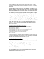
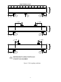
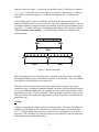
INTRODUCTION
AISIWIN is a Windows®-based program for calculating section properties, load
capacity, and allowable spans for cold-formed steel stud, joist and track sections.
Calculations are based on the 2007, 2004 (Supplement) and 2001 ”North American
Specification for the Design of Cold-Formed Steel Structural Members”, (NASPEC) U.S. provisions only - as well as the American Iron and Steel Institute (AISI)
“Specification for the Design of Cold-Formed Steel Structural Members” (the
Specification). The 1996 Specification (ASD and LRFD), and the 1999 Supplement are
included.
For web crippling and shear of punched members, the 1996 specification did not contain
provisions. For this case, ICBO AC46 as adopted prior to 1996 is used for web crippling
and shear reductions at punchouts.
For sheathing braced design of studs with combined bending and axial loads, for codes
later than 2004, the AISI Standard “North American Standard for Cold-Formed Steel
Framing – Wall Stud Design” 2007 edition [Wall Stud Standard] is used. This standard
is also used in the ‘Stud to Track’ and ‘Deflection Track’ module.
DISCLAIMER
The developers have extensively verified this program and documentation. However, in
using the program and documentation, the user accepts and understands that no warranty,
expressed or implied, is made with regard to the accuracy of the results of the program.
The program is intended for use by qualified professionals familiar with the design of
cold-formed steel members. The user must understand the basis for calculations and
independently verify results.
SETUP
AISIWIN is designed to operate in the Windows® environment. Before setting up the
program, it is important to close all applications, including MS Office®. To setup
the program, insert the CD in the appropriate drive and run Setup.exe. The setup routine
will automatically create a sub-folder called “AISIWIN” within your ‘Program Files’
folder, or you can choose to install it to another location.
Note: If you choose to install AISIWIN to a folder other than the default, the
program may not be able to locate the section database immediately. To select a
database, choose Settings then Database from the menu and proceed with your
selection. Then save your choice as the default by clicking on the button with that
label.
AISIWIN can be started by any of the typical methods used to run an application in
Windows.
1
ORGANIZATION OF THE USER’S MANUAL
This User’s Manual is divided into several parts. The first two sections give general
information regarding the use of the toolbar and menu systems and a basic overview of
section data input. The remaining sections detail each of the operations that can be
initiated from the drop-down menus.
Where Specification sections are referenced they are given first as the 2007 NASPEC
reference followed by a “/” and the earlier edition Specification references.
DIFFERENCES BETWEEN Version 8.0 and Version 7.0
AISIWIN v8.0 has several features not included in previous versions:
•
•
•
•
•
•
•
•
The AISIWIN Solver feature now includes a Torsion tool based on the 2007
NASPEC.
A ‘Stud to Track’ calculator has been added based on the AISI “Standard for
Cold-Formed Steel Framing – Wall Stud Design” provisions.
A connection module has been added for screw and welded connections.
A torsion analysis module has been added for the calculation of R per section
C3.6 of the 2007 NASPEC for uniformly loaded simple span members.
Provisions of the 2007 NASPEC (US only) have been added including torsion
and distortional buckling for flexure and axial capacity. The toolbar contains
input text boxes for Kφ for both axial and flexural loads.
Solver modules have been enhanced to include the option to find studs of a given
size in both 33 and 50 ksi.
Section property output has been revised to include a section diagram and be
displayed in a format similar to most stud manufacturer’s.
Wind load data tables per ASCE 7-05 for buildings <= 60 feet in height are
included, and the wind pressures can be automatically loaded into the wall solver
and table modules.
The 2007 NASPEC incorporates some significant changes from the 2001 and 2004
provisions, specifically with regard to combined flexural and torsional stresses and
distortional buckling. These changes can lead to decreases in capacity.
Note that for distortional buckling, strength is based in part on the restraint provided by
attached materials. This is accounted for in the Kφ factor. Unfortunately, there is little
published guidance on appropriate values of Kφ. AISIWIN does allow for input values of
Kφ, but it is up to the user to input appropriate values. Leaving Kφ = 0 is conservative.
While the 2004 Supplement to the NASPEC eliminated the provisions for sheathing
braced design of axial load-bearing studs, the 2007 Wall Stud Standard does incorporate
provisions with specific limits on capacity. When the Code is set to 2007, the provisions
of the Wall Stud Standard are used for sheathing braced design of studs with combined
bending and axial loads.
2
THE AISIWIN TOOLBAR AND MENU
At startup, AISIWIN displays a menu, toolbar and Command bar which together control
overall operation of the program. The Command bar and menu direct the flow of the
program and gives the user access to each of the design and settings modules. Each of
the Command bar and menu items is described in more detail later in this manual.
The toolbar contains the following controls that are common to each of the individual
design modules:
Project input box
Section drop down boxes
Fy drop down box
Punched/Unpunched toggle
The calculate button
The printer button
The view section properties button
Bearing length drop down boxes for interior and end bearing.
Distortional Buckling Kφ inputs (2007 NASPEC only)
The Project input box allows the user to enter a project name or heading that will appear
on printed reports. To enter a heading, click on the box and type.
The Section drop down boxes are used to input section geometry information from the
database (if in database input mode), or to input a special designation (if in custom
geometry input mode). At startup, input is in the database mode, with information from
the default database loaded into the drop down boxes. The section designation can be
changed at any time, and, the physical/structural properties, allowable spans or load
capacity will automatically be re-calculated.
The Fy drop down box is used to change the yield point (to 33 or 50 ksi) at run time
without leaving the design modules. Note that only 33 and 50 ksi are available from the
dropdown regardless of the yield point set in the database. When 33 ksi is selected, an
ultimate stress of 45 ksi is assumed for cold-work of forming calculations. When 50 ksi
is selected, an ultimate stress of 65 ksi is assumed for cold-work of forming calculations.
3
The Punched/Unpunched toggle is used to specify if the section will have web
punchouts. Some manufacturers will supply their standard products either with or
without punchouts. This applies only to the database-input mode.
The =, or calculate button is used in the design modules to fill in the load or span tables.
After providing all of the appropriate input information on the design forms, clicking the
= button fills in the table with allowable spans or loads. In the design modules, any time
a change is made to the inputs, the table automatically clears. To regenerate the tables
with the revised inputs, click the = button. When the section is changed via the dropdown boxes on the toolbar, the allowable spans or loads is automatically updated and
there is no need to click the = button.
From the design modules or the section property view form, clicking the printer button
sends the information on screen to the printer. Note that the Wind Pressure and
Deflection Limit tables are not printable.
The view section property button allows the user to view, on screen, the geometry, steel
properties and physical/structural properties of the current section.
Bearing length drop-down boxes are used to input the end and interior bearing lengths
used in web crippling calculations. Some modules do not use web-crippling information.
However, a change in either bearing length drop down will clear the tables in all of the
design modules.
The Kφ input boxes for Distortional Buckling allow the user to input appropriate values
of Kφ (for both flexural and axial capacity) to account for restraint against distortional
buckling provided by attached materials. Distortional buckling was adopted in the 2007
NASPEC so for earlier codes, these inputs are not available and will not be used. When
designing per the 2007 NASPEC, the input values of Kφ will be incorporated into the
distortional buckling for both flexural and axial strength. Choosing an appropriate value
of Kφ can be very complicated since it is dependent on the stiffness of the various
materials and their attachments. Current research suggests that Kφ for gypsum board
should be taken as zero. When a realistic value of Kφ is not well known, it is
recommended that the values be left at the default zero values.
GEOMETRY AND STEEL PROPERTY INPUT
Most often, the sections used in cold-formed steel design are standard sections. To take
advantage of this, AISIWIN uses section databases to input geometry and steel property
information. Users can generate their own databases by simply editing an existing
database text file and saving to a new name to accommodate their needs or use one of the
databases supplied with the program.
It is sometimes necessary to design a section that is not part of any manufacturer’s
standard product line. This can easily be done within AISIWIN by selecting one of two
custom-geometry input methods. The first custom input mode allows the user to take
4
data from a standard database shape and modify it. The second mode provides for total
flexibility of input with no information from the database. Each of these methods is
described in the paragraphs that follow.
VIEWING PHYSICAL/STRUCTURAL PROPERTIES
With the geometry entered, physical/structural properties can be viewed by clicking the
view section properties command button or by selecting Display Section Properties
from the Section menu item.
Input geometry and steel properties are first checked for completeness. If the information
is incomplete, a message will be displayed indicating what information needs to be
entered or corrected. In addition, element width-to-thickness ratios are verified per
Specification section B1.1. If these ratios exceed Specification limits, a message will be
displayed indicating the element which requires modification. When calculations are
being performed using the 1999 Supplement or later Specifications, punchout dimensions
are also verified relative to the shear and web crippling reductions. If the punchouts fall
outside the published parameters for the reduction equations a warning message is
shown, but the calculations will proceed.
For ASD versions of the Specification, allowable moment, shear and web crippling
values are given. If an LRFD version has been chosen, the nominal strengths multiplied
by the appropriate φ factor are displayed.
If the input is complete and the element dimensions comply with the code limits, gross
and effective properties are calculated for both the strong (X-X) and weak (Y-Y)
directions. In addition, torsional properties, allowable shear and web crippling loads and
the quantity Pno/Ω (ASD), φPn0 (LRFD) for use in interaction equation C5.2.1-2/C5.2 are
determined. For Boxed or Back-to-Back members, the properties shown are for the
composite section assuming they are adequately interconnected. A brief discussion of the
various properties follows:
Gross Properties
Each of the gross properties about the strong axis is based on the full, unreduced
geometry of the section.
For members with punchouts, the net area at punchout locations is displayed. For
both punched and unpunched members, the weight per unit length (lb/ft) is
calculated based on the gross, unreduced area of the section.
Effective Section Properties
The moment of inertia, Ixx, for deflection is calculated according to Procedure I of
the Specification (assuming the design moment equals the allowable moment
capacity). Except for when using the 1999 Supplement or later specifications,
these properties are not reduced for web punchouts.
5
Section modulus (Sxx) and allowable bending moment, Ma-xx (ASD) or φMn-xx
(LRFD) are calculated at the yield stress (as modified for cold-work of forming if
appropriate).
Allowable shear of the gross section away from punchouts, if present is given. If
punchout dimensions are input, the allowable shear will be calculated for both the
punched and unpunched cases in accordance with the AISI/NASPEC provisions.
The calculation of effective properties for bending about the weak axis of single
members considers cases for both the web in compression and in tension and
records the minimum value of section modulus, Syy, and allowable weak-axis
bending moment Ma-y (ASD) or φMn-y (LRFD). For the case of the web in
compression with punched webs, the effective web width is based on the
unstiffened strip approach in the Specification. For C-studs, flanges are treated as
webs with stress gradients per Specification section B2.3. The effective flange
widths of channel studs and track sections are based on Specification section B3.2
for the 2001 NASPEC and earlier. For the 2004 Supplement to the NASPEC,
section B3.2 is used. Weak-axis flexural strength is not computed for boxed or
back-to-back sections.
Torsional Properties (single and boxed members)
For single members, the following torsional properties are given:
St. Venant torsion constant, J
Warping torsional constant, Cw
Distance from the shear center to the centroid along the X-axis, Xo
Distance from the shear center to the web centerline, m
Polar radius of gyration about the shear center, Ro
Beta = 1-(Xo/Ro)2
For boxed members, the maximum unbraced length for full moment capacity, Lu
is given (1999 through 2007 Specification). For the 1996 AISI Specification, the
maximum allowable unbraced length for flexure is given.
Lateral Buckling Properties for Flexure
For back-to-back members, the moment of inertia of the compression portion, Iyc
is given.
Warping Torsional Properties (2007 NASPEC only) – Single Members
For single members and the 2007 NASPEC, the following properties for
calculating warping torsional stresses in single members are given:
Constant, a = (E*Cw/(G*J))1/2
The section modulus at the tip of the lip (for determining flexural stress at this
location as used in the calculation of R), Sxx(lip)
6
The normalized warping function at point, i on the section, Wn(i). The locations
numbered 1-6 are shown on the section diagram at the top of the page.
Web Crippling Loads
Allowable (Pa), or nominal (φPn), web-crippling loads are displayed for four
conditions as defined in Figure 1. Allowable (ASD) or nominal (LRFD) loads for
boxed members are taken as twice that of a single member. For back-to-back
members, the provisions for I-sections are used. In addition, if punchout
dimensions are given, a reduction factor is shown. This reduction factor is
calculated in accordance with the AISI/NAS Specifications for 1999 or later or
ICBO AC46 for earlier specifications and will be applied to the web crippling
capacity, if requested, for a given application. Refer to the instructions for
individual applications for more information regarding the application of the web
crippling reduction factor.
No web crippling loads are displayed if the web height-to-thickness ratio exceeds
200 since such members require stiffeners at all concentrated loads.
The 2001 NASPEC and later specifications have provisions for “Fastened to
Support” and “Unfastened” web crippling. However, provisions are not included
for all section types and web crippling conditions. AISIWIN uses the “Fastened
to Support” values whenever possible and resorts to the “Unfastened” data where
there is no other alternative. As such, if members are not intended to be fastened
to supports, the web crippling strength of the members should be determined
using a method other than AISIWIN.
7
UNIFORM LOAD
D
2
2
1
> 1.5D
< 1.5D
> 1.5D
> 1.5D
D
2
1
> 1.5D
< 1.5D
< 1.5D
< 1.5D
D
4
3
> 1.5D
#
< 1.5D
REPRESENTS WEB CRIPPLING
CONDITION NUMBER
Figure 1. Web crippling conditions
8
Using the Menu
File
From File, the user can select Print or Exit. Selecting Print has the same affect as
clicking on the toolbar printer button. The Exit item closes AISIWIN; any current
information will be lost.
Solver
The Solver Menu item provides access to the Wall, Ceiling, Floor and Header Solver
modules. These powerful new tools allow design of wall, ceiling, floor and header
members by inputting your exact design requirements and allowing AISIWIN to find the
members that can meet the requirements.
The Solver menu also includes the calculator for single Deflection Track.
The Wall Solver selects simple span wall studs fully or mechanically braced and with or
without axial loads. The following inputs are required for Wall solver to do its job:
•
•
•
•
•
•
•
•
•
Wall Height
Deflection Limit
Wind Pressure
Axial load (if any)
Load multiplier for strength (load factors for LRFD)
Load multiplier for deflection
Flexural bracing (full, discrete or optimized)
Axial bracing (not required if axial load = 0)
Web crippling and shear parameters. If “Web Stiffeners at Supports O.K.?” is
checked, some of the studs listed as meeting the input criteria may require web
stiffeners. If it is not checked, studs requiring web stiffeners will not be listed
In addition, the range of stud sizes to be investigated is required. Choose a stud depth,
range of flange sizes and range of thicknesses. The choice of including Fy = 33 and 50 ksi
for all sections is also available by checking the box so labeled. Note that if the 33/50 ksi
check box is not checked, the search will include Fy per the currently selected database.
AISIWIN will search the full range of studs to find all of those meeting the input
requirements.
The stud spacing can be fixed, or set to a selected range and increment. If a single
spacing is input, only that spacing will be checked. If a range of spacings is indicated, all
of the studs and spacings within the range will be checked. As such, an individual stud
size may be listed several times at different spacings.
Flexural bracing can be optimized by selecting “Optimize” from the Flexural Bracing
dropdown. Note that if Flexural Bracing is set to “Optimize”, only one stud spacing can
be selected. Flexural bracing is optimized when KyLy and KtLt are such that the flexural
9
capacity just meets the flexural demand. Note that if an axial load is entered, flexural
bracing optimization is not available.
For the 2007 NASPEC, torsion can also be included. To include torsional analysis, check
the box labeled ‘Include Torsion’. The torsional lever arm can be taken from the shear
center to either the Web Center, Centroid (Xcg), or the Flange Center. Torsional bracing
is taken to be the same as the input flexural bracing. Note that for fully braced members,
it is assumed that torsion is also fully restrained so the ‘Include Torsion’ check box is
disabled. For a more complete discussion of how torsional stresses are calculated and
combined with bending stresses, see the section titled ‘Torsion’ below.
Note that torsion is considered only in interaction with bending. Combined bending and
axial loads are considered as a separate interaction without the torsional reduction factor,
R, being applied to flexural strength.
The basic assumptions for the wall Solver are the same as for the fully braced,
mechanically braced, and axial load bearing wall tables described below.
To find the studs meeting the input criteria, click “GO”. AISIWIN will search the range
of studs and list all of the studs meeting the criteria. Select a stud from the list by
clicking on it. Preview your selection by clicking “Preview”. To get a paper copy by
click “Print” or from the Preview screen, click on the printer button on the toolbar.
The Ceiling Solver selects simple span ceiling joists, fully or mechanically braced. The
following inputs are required for Ceiling Solver to do its job:
•
•
•
•
•
•
•
•
•
Joist Span
Deflection Limit
Dead Load
Live Load (if any)
Wind Load
Load multipliers for strength (load factors for LRFD)
Wind Load multiplier for deflection
Flexural bracing (full, discrete or optimized)
Web crippling and shear parameters. If “Web Stiffeners at Supports O.K.?” is
checked, some of the joists listed as meeting the input criteria may require web
stiffeners. If it is not checked, joists requiring web stiffeners will not be listed.
In addition, the range of joist sizes to be investigated is required. Choose a member
depth, range of flange sizes and range of thicknesses. The choice of including Fy = 33 and
50 ksi for all sections is also available by checking the box so labeled. Note that if the
33/50 ksi check box is not checked, the search will include Fy per the currently selected
database. AISIWIN will search the full range of joists to find all of those meeting the
input requirements.
The joist spacing can be fixed, or set to a selected range and increment. If a single
spacing is input, only that spacing will be checked. If a range of spacings is indicated, all
10
of the joists and spacings within the range will be checked. As such, an individual joist
size may be listed several times at different spacings.
Flexural bracing can be optimized by selecting “Optimize” from the Flexural Bracing
dropdown. Note that if Flexural Bracing is set to “Optimize”, only one stud spacing can
be selected. Flexural bracing is optimized when KyLy and KtLt are such that the flexural
capacity just meets the flexural demand.
For the 2007 NASPEC, torsion can also be included. To include torsional analysis, check
the box labeled ‘Include Torsion’. The torsional lever arm can be taken from the shear
center to either the Web Center, Centroid (Xcg), or the Flange Center. Torsional bracing
is taken to be the same as the input flexural bracing. Note that for fully braced members,
it is assumed that torsion is also fully restrained so the ‘Include Torsion’ check box is
disabled. For a more complete discussion of how torsional stresses are calculated and
combined with bending stresses, see the section titled ‘Torsion’ below.
To find the joists meeting the input criteria, click “GO”. AISIWIN will search the range
of joists and list all that meet the criteria. Select a joist from the list by clicking on it.
Then preview your selection by clicking “Preview”, or get a paper copy by clicking
“Print.”
The Floor Solver selects floor joists, in one-span or two equal span configurations. The
following inputs are required for Floor Solver to do its job:
•
•
•
•
•
•
•
•
•
Joist Span
Dead Load
Live Load
Span Condition (one or two-equal spans)
Alternate span loading check (for two-equal span condition only)
Total Load Deflection Limit
Live Load Deflection Limit
Load Factors (LRFD Only)
Web crippling and shear parameters. If “Web Stiffeners at Supports O.K.?” is
checked, some of the joists listed as meeting the input criteria may require web
stiffeners. If it is not checked, joists requiring web stiffeners will not be listed.
In addition, the range of joist sizes to be investigated is required. Choose a member
depth, range of flange sizes and range of thicknesses. The choice of including Fy = 33 and
50 ksi for all sections is also available by checking the box so labeled. Note that if the
33/50 ksi check box is not checked, the search will include Fy per the currently selected
database. AISIWIN will search the full range of joists to find all of those meeting the
input requirements.
The joist spacing can be fixed, or set to a selected range and increment. If a single
spacing is input, only that spacing will be checked. If a range of spacings is indicated, all
of the joists and spacings within the range will be checked. As such, an individual joist
size may be listed several times at different spacings.
11
To find the joists meeting the input criteria, click “GO”. AISIWIN will search the range
of joists and list all that meet the criteria. Select a joist from the list by clicking on it.
Then preview your selection by clicking “Preview”, or get a paper copy by clicking
“Print.”
The Header Solver selects single, boxed or back-to-back headers, for simple span
conditions. The following inputs are required for Header Solver to do its job:
•
•
•
•
•
•
•
Header Span
Dead, Live and/or Wind Load
Load multipliers (or load factors for LRFD) for strength for each load type
Load multiplier for deflection, wind load only
Deflection Limit
Flexural bracing
Web crippling and shear parameters. If “Web Stiffeners at Supports O.K.?” is
checked, some of the joists listed as meeting the input criteria may require web
stiffeners. If it is not checked, joists requiring web stiffeners will not be listed.
In addition, the range of header sizes to be investigated is required along with the
configuration – single, boxed or back-to-back. Choose a member depth, range of flange
sizes and range of thicknesses. The choice of including Fy = 33 and 50 ksi for all sections
is also available by checking the box so labeled. Note that if the 33/50 ksi check box is
not checked, the search will include Fy per the currently selected database. AISIWIN will
search the full range of headers to find all of those meeting the input requirements.
Flexural bracing can be optimized by selecting “Optimize” from the Flexural Bracing
dropdown. Flexural bracing is optimized when KyLy and KtLt are such that the flexural
capacity just meets the flexural demand.
For the 2007 NASPEC, torsion can also be included. To include torsional analysis, check
the box labeled ‘Include Torsion’. The torsional lever arm can be taken from the shear
center to either the Web Center, Centroid (Xcg), or the Flange Center. Torsional bracing
is taken to be the same as the input flexural bracing. Note that for fully braced members,
it is assumed that torsion is also fully restrained so the ‘Include Torsion’ check box is
disabled. For a more complete discussion of how torsional stresses are calculated and
combined with bending stresses, see the section titled ‘Torsion’ below.
To find the headers meeting the input criteria, click “GO”. AISIWIN will search the
range of joists and list all that meet the criteria. Select a joist from the list by clicking on
it. Then preview your selection by clicking “Preview”, or get a paper copy by clicking
“Print.”
The Deflection Track Solver determines allowable reactions on track legs of single
deflection tracks. Either the provisions of the Steel Stud Manufacturer’s Association
(SSMA) Tech Note 1, or the AISI “Standard for Cold-Formed Steel Framing – Wall Stud
Design” 2007 Edition, section C4.3 may be used.
12
Inputs required include the gap dimension, stud flange width and stud spacing. Based on
these inputs, the allowable top of stud reaction is computed. Intermediate results such as
the effective plate bending width (beff for SSMA Tech Note 1, and Wdt for the AISI
“Standard for Cold-Formed Steel Framing – Wall Stud Design.”) are also displayed. Note
that the allowable reactions are not modified for duration of load.
Note that the section input must be a track for calculations to proceed. The AISI
“Standard for Cold-Formed Steel Framing – Wall Stud Design” includes a number of
limitations based on the range of the testing program. If the inputs are outside these
parameters, warning messages will be displayed, but calculations will display. Where
warning messages are displayed, the user must understand that the output
presented are extrapolations of the test data and should be treated accordingly.
To print a copy of the input and output for the Deflection Track Solver, click the printer
button on the toolbar.
The Connections solver calculates the capacity of screwed and welded connections.
Select the type of connection by clicking on ‘Screws’ or ‘Welds’ in the upper right
corner.
For screw connections, the inputs include the screw size (including head/washer
diameter). Note that the screw size can be selected by standards sizing (e.g. No. 8), or a
diameter can be numerically input. The thickness, T1 of the steel in contact with the
screw head, and T2, the steel not in contact with the screw head are also input along with
their respective ultimate stress, Fu. If the screw is near the edge of a sheet, an edge
distance can also be entered.
Based on the inputs provided, the screw shear, pullout and pullover strength for both
ASD and LRFD are displayed. In addition, the minimum required strength of the screw
itself is also displayed.
For welded connections, Fillet or Flare Groove type welds can be selected. Then, the
thickness and ultimate stress, Fu, of the connected part is input. Note that for welds of
two sheets, the weld capacity should be calculated for each sheet and the minimum value
used for design.
For sheets thicker than 0.100 inches, the electrode tensile strength must also be input.
Based on the inputs provided, the nominal, Pn, the ASD value, Pn/Ω, and the LRFD value
φPn are provided for longitudinal and transverse welds.
The Torsion solver calculates the value of the reduction factor ‘R’ based on section C3.6
of the 2007 NASPEC for single, simple span members. Input parameters include the
section (from the main toolbar) span length, torsional bracing, torsional lever arm
location and uniform load. However, the input value is used in the determination of the
warping torsional and flexural stresses shown in the output.
13
Based on the values input, the torsional lever arm dimension, maximum primary moment
and uniform torque are determined and displayed.
In addition, the various section properties relevant to calculating torsional warping
stresses are calculated and shown. The majority of these properties are self-explanatory.
The constant ‘a’ is less familiar, but is defined by the equation shown and is routinely
used in the determination of warping torsional stresses. Sxx(lip) is the value of the section
modulus of the section taken at the tip of the stiffening lip. This value is of interest
because in some instances, the warping torsional stresses and the sum of the warping
torsional and primary flexural stresses are maximized at the tip of the lip – thus
controlling the value of R.
The normalized warping function, Wns, at points 1-6 around the section is also given.
The diagram to the right indicates the locations for each of the points.
The values of θ’’, warping torsion stress (F_torsion), primary bending stress (Fb), and
total stress (Ftotal), are calculated for each of the points 1-3 in the compression region of
the section. Values are determined at brace locations when bracing occurs, as well as at
mid-span since either location could control.
The value of R is calculated for the point of maximum combined stresses. Note that for
sections with stiffening lips, if the maximum combined stresses occur at the junction of
the web and the flange, the value of R is allowed to be increased by a factor of 1.15. Note
also that the value of R is limited to a maximum value of 1.0 by code. The limitation is
not displayed in the torsion output for illustration purposes, but it is applied in all of the
Solver and Design Tables modules where torsion can be applied.
Tables
The Tables menu item provides access to the tabular design modules where users can
determine spans and loads for various applications. It also provides access to the Wind
and Deflection Limit data tables.
Wall tables are divided into two categories, Non-Axial Load Bearing and Axial LoadBearing. Non-Axial Load Bearing walls are then subdivided into Fully Braced, and
Mechanically Braced walls.
Non-Axial Load Bearing, Fully Braced Walls
Maximum wall heights are tabulated for walls that are fully braced by sheathing or other
means and support only lateral bending loads. Simple span, two equal spans, or two or
more equal spans can be considered. Using the input lateral load, heights are determined
based on flexure (including distortional buckling when appropriate), shear, web crippling
and deflection. For multi-span applications, combined bending and shear, and combined
bending and web crippling is also considered.
14
The applied lateral load is input in the box labeled Nominal Load. For both ASD and
LRFD design the load can be modified for strength checks as well as deflection. For ASD
the nominal load will be multiplied by the load multipliers for strength and deflection
when making the respective checks. When using LRFD input, the unfactored lateral load
and the appropriate load factor. All LRFD strength checks are based on factored loads,
while deflection is checked with the nominal load multiplied by the load factor for
deflection. Heights based on flexure assume the studs are fully stabilized and that the
allowable bending moment is the allowable moment at yield.
Choose the span condition by selecting one, two equal, or two or more equal spans.
For two or more equal, continuous spans, the minimum span based on two or three equal
span conditions is displayed.
Heights based on shear consider the maximum shear at the ends of the studs and the
allowable shear force (or Pu ≤ φPn for LRFD) in the web. If the stud being considered is
punched, the user has the option of considering the web punched or unpunched in the
zone of maximum shear. For joists with punched webs, (the Punched/Unpunched toggle
reads “punched”, or punchout dimensions were entered in the custom geometry mode), if
the box labeled “Consider Punched Near supports?” is checked, allowable shear and
web crippling will be reduced in accordance with the ICBO AC46 (for 1996 and earlier
Specifications) or the appropriate specification provisions.
Heights based on web crippling consider the maximum reaction and the web crippling
capacity for the stud. If the webs of the studs are stiffened, (the box labeled “Require
Web Stiffeners at Supports?” is checked), web crippling will not be considered. If web
crippling is to be considered, the bearing lengths can be modified from the toolbar. For
members with web height-to-thickness ratios exceeding 200, wall heights will not be
calculated unless the “Require Web Stiffeners at Supports?” box is checked.
Wall heights are displayed for three stud spacings and deflection ratios, any of which
may be modified by the user. Stud spacing is input in inches (mm), and deflection limits
are input as a ratio of the overall wall height.
Click the calculate button on the toolbar to fill in the allowable wall heights table
Non-Axial Load Bearing, Mechanically Braced walls
Walls that do not have adequate bracing on each flange over the entire length of the stud
can be designed as mechanically braced walls. The design criteria for mechanically
braced walls are similar to that for fully braced walls, except that the flexural capacity is
based on the lateral stability of the stud in bending in accordance with Specification
section C3.1.2.
The bending coefficient to account for moment gradient, Cb, varies based on the span and
bracing configuration. For simple spans, Cb is taken as 1.14 for unbraced, 1.3 for midspan braced and 1.0 for other bracing configurations. For the two equal, continuous
spans, Cb is taken as 2.083 for the unbraced condition and conservatively taken as 1.0 for
15
all other bracing configurations. For three equal spans, Cb is taken as 1.538 for unbraced
flanges and 1.0 for all other conditions.
The applied lateral load is input in the box labeled “Nominal Load.” For both ASD and
LRFD design the load can be modified for strength checks as well as deflection. For ASD
the nominal load will be multiplied by the load multipliers for strength and deflection
when making the respective checks. When using LRFD design input the unfactored
lateral load and the appropriate load factor. All LRFD strength checks are based on
factored loads, while deflection is checked with the nominal load multiplied by the load
factor for deflection.
The deflection limit must be entered as a ratio of the overall wall height (i.e. for a
specified deflection limit of L/480, enter 480 in the box labeled Deflection Limit L/
).
Choose the span condition by selecting one, two equal, or two or more equal spans.
Allowable heights consider the same items described for fully braced walls.
Wall heights are displayed for three stud spacings and three bracing configurations. Stud
spacings are entered in inches (mm). The lateral bracing interval is entered either in
inches (mm), or as “NONE”, “MID Pt”, or “THIRD Pt” points. The user may change
each of the stud spacings and lateral bracing intervals.
For the 2007 NASPEC, torsion can also be included. To include torsional analysis, check
the box labeled ‘Include Torsion’. The torsional lever arm can be taken from the shear
center to either the Web Center, Centroid (Xcg), or the Flange Center. Torsional bracing
is taken to be the same as the input flexural bracing. For a more complete discussion of
how torsional stresses are calculated and combined with bending stresses, see the section
titled ‘Torsion’ above.
Click the calculate button on the toolbar to fill in the heights table
Axial Load-Bearing Walls
AISIWIN calculates allowable axial loads (ASD) or maximum factored axial loads, Pu
(LRFD) for studs with combined bending and compressive loads. Interaction formulas
per Specification section C5 are used to determine the maximum axial load, P, which the
stud can carry in combination with the user specified bending load by setting the
interaction values to 1.0.
Input the overall wall height in the drop down box labeled “Overall Wall Height”.
Bending moment is calculated based on a simple span condition at the specified wall
height. If the box labeled “Consider Fully Braced for Bending?” is checked, the
moment capacity used in the interaction equations will be the moment capacity at yield.
If this box is not checked, lateral stability will be considered in accordance with
Specification section C3.1.2 with KyLy and KtLt equal to the bracing interval input.
16
Lateral loads, in psf (N/m2), are input in the drop down box labeled “Lateral Load”.
The combined bending and axial load interactions will be checked using the load
multipliers on both lateral and axial loads as input. If, however, the maximum allowable
load, P, including the load multipliers exceeds the allowable pure axial load of the stud
under concentric axial load only, without a multiplier, the unmodified allowable pure,
concentric axial load of the stud will be displayed. Deflection is calculated at the input
lateral load multiplied by the factor for deflection.
For LRFD design, input the unfactored lateral load and the load factor. Deflection is
calculated at the nominal load multiplied by the load factor for deflection.
Axial loads are calculated for three weak-axis bracing intervals and three on-center stud
spacings. Modifying the contents of the associated drop down boxes can change any of
these parameters. On-center stud spacings are entered in inches (mm). For weak-axis
bracing, the input can be in inches (mm), or “NONE”, “MID” or “THIRD” can be
chosen. If data is entered that is not numerical or one of the three interval designations,
the weak-axis bracing interval will be considered to be the overall wall height.
For calculating stresses in accordance with Specification section C4, the unbraced length
for torsion (KtLt) is taken as the spacing of weak axis bracing (KyLy). In the interaction
equation (C5.2.1-1 / C5-1) of the Specification, Cmx = 1.0. For boxed members, torsional
buckling is not considered.
AISI Specifications prior to the 2001 NASPEC required that Cb (as used in the flexural
stability checks) be taken as 1.0 for members with axial loads. The 2001 NASPEC
removed this limitation. AISIWIN uses Cb = 1.14 for unbraced members, 1.3 for “MidPt.” braced members and 1.0 (conservatively) for all other conditions.
In addition to mechanical bracing, axial loads for single and back-to-back members are
displayed for studs with identical sheathing on each flange in accordance with
Specification section D4 (except when the 2004 Supplement to the NASPEC is chosen).
The NASPEC/AISI Specifications do not include provisions for sheathing braced design
of boxed members. For sheathing braced design, the moment capacity, (Ma for ASD or
φMn for LRFD), is taken as the moment at yield. The sheathing parameters assumed by
AISIWIN correspond to 3/8 to 5/8-inch thick gypsum board (See Specification Table
D4). There are several limitations on member configuration in the Specification. When
these limits are exceeded, a warning message will appear. The calculations will still
proceed, but the results may not be in conformance with Specification provisions.
For the 2007 NASPEC, sheathing braced design is based on the “North American
Standard for Cold-Formed Steel Framing – Wall Stud Design” 2007 edition. The
sheathing is assumed to be ½ inch gypsum sheathing with No. 6 fasteners at 12 inches on
center.
The deflection ratio is also displayed for each stud spacing so the user can compare the
deflection with the applicable serviceability criteria. In addition, the maximum KL/r
ratio (KxLx/rx or KyLy/ry) is calculated and displayed.
17
Web crippling is not considered for the determination of axial loads, but should be
checked against the allowable web crippling load for the particular stud and bearing
condition. Web crippling capacity is given at the bottom of the section property printouts.
The provisions for built-up members with axial load changed in the 2001 NASPEC from
previous versions of the Specification. Section C4.5 of the 2001 NASPEC defines a
modified KL/r based on the fastener spacing between members, the slenderness ratio of
the built-up section and the minimum radius of gyration of the individual sections making
up the built-up member. As such, fastener spacing is required for calculating axial
capacity of boxed and back-to-back members using the 2001 NASPEC. This
requirement is reflected in AISIWIN with the addition of a dropdown input for fastener
spacing that appears when boxed or back-to-back members are selected.
Note that section C4.5 of the 2001 and later NASPEC also places limits on the spacing of
the fasteners of built-up members. If those limits are not met, AISIWIN will not
calculate axial capacities. There are also requirements for connections at ends of
built-up members and for fastener capacity adopted in the 2001 NASPEC. It is
important that AISIWIN users read and understand these requirements to ensure
that their designs meet these requirements.
Note that torsion is not considered in combination with axial loads. For sections that may
be controlled by bending and torsion, see ‘Non-Axial Load Bearing, Mechanically
Braced walls’ above.
For the 2007 NASPEC, distortional buckling is considered for both flexural and axial
capacities used in the interactions where appropriate.
Floors
AISIWIN calculates maximum floor joist spans based on user input dead and live loads
and deflection limits for live and total loads. The applied dead and live loads are entered
in the drop down boxes labeled “DL” and “LL” respectively. Deflection limits for dead
and total loads are similarly entered in the drop down boxes labeled “Total Load L/ “
and “Live Load L/ .” For LRFD design, the unfactored dead and live loads are input in
conjunction with their individual load factors.
For joists with punched webs, (the Punched/Unpunched toggle reads “punched”, or
punchout dimensions were entered in the custom geometry mode), if the box labeled
“Consider Punched Near supports?” is checked, allowable shear and web crippling
will be reduced in accordance with the ICBO AC46 (for 1996 and earlier Specifications)
or the appropriate specification provisions.
Spans are calculated for joists both with web stiffeners and without. Single span and two
equal, continuous span conditions are considered for three on-center joist spacings. For
the case of two equal spans, the span is the distance from an outside support to the center
18
support as shown in Figure 2. Spans with web stiffeners may be followed by a notation
“i”, “e” or “a” to indicate where web stiffeners are required. The notation “i” indicates
web stiffeners at interior supports, “e” indicates end supports and “a” indicates all
supports.
Some building codes require serviceability checks that consider alternate span live
loading. For deflection of a two-span joist, this can be the controlling criterion. The user
can choose whether to consider alternate span loading for deflection calculations on twospan joists. To consider deflection with alternate span loading, click on the box labeled
“Check Alternate Span Loading.” For LRFD design, deflection is calculated with
unfactored loads.
Span
Span
Span
Figure 2. Span measurement.
Allowable single spans are determined as the minimum value from: flexure (including
distortional buckling), shear, total deflection and live load deflection. For joists without
web stiffeners, web crippling is also considered.
The same criteria used to determine allowable single spans are used for two equal,
continuous spans. In addition, combined bending and shear (AISI Specification Section
C3.3), and combined bending and web crippling for joists without web stiffeners (AISI
Specification section C3.5) are considered. If the web height-to-thickness ratio exceeds
200, web stiffeners are required at supports and, as such, no spans are calculated for the
unstiffened case.
Ceilings
Ceilings are generally sheathed on only their bottom flanges. Therefore, the stability of
ceiling joists in bending must be calculated in accordance with Specification section
C3.1.2. Ceiling bending loads also may consist of several components (e.g. dead, live
and wind). The calculation of ceiling joist spans is nearly identical to that for non-axial
load bearing walls, mechanically braced.
19
The applied loads are input in the boxes labeled Dead Load, Live Load and Wind
Load. For both ASD and LRFD design the individual loads can be modified for strength
checks as well as deflection. For ASD the various bending loads will be multiplied by the
load multipliers input for strength and deflection when making the respective checks.
When using LRFD input, the unfactored flexural load and the appropriate load factor.
All LRFD strength checks are based on factored loads, while deflection is checked with
the nominal load multiplied by the load factor for deflection.
Note that AISIWIN checks only the individual load combination entered. Specific load
combinations required by a particular building code are not incorporated into the
program.
The deflection limit must be entered as a ratio of the overall joist span (i.e. for a specified
deflection limit of L/480, enter 480 in the box labeled “Deflection Limit L/ “).
Choose the span condition by selecting one, two equal, or two or more equal spans.
Allowable spans consider the same items described for mechanically braced walls.
Spans based on web crippling consider the maximum reactions and the web crippling
capacity of the joist. If the webs of the joists are stiffened, (the box labeled “Require
Web Stiffeners at Supports?” is checked), web crippling will not be considered. If web
crippling is to be considered, the bearing lengths can be modified from the toolbar. For
members with web height-to-thickness ratios exceeding 200, wall heights will not be
calculated unless the “Require Web Stiffeners at Supports?” box is checked.
Spans are displayed for three joist spacings and three bracing intervals. Joist spacings are
entered in inches (mm). The lateral bracing interval is entered either in inches (mm), or
as “NONE”, “MID Pt”, “THIRD Pt” or “FULL”. If “FULL” bracing is chosen, the
moment capacity will be considered the moment capacity at yield. The user may change
each of the joist spacings and lateral bracing intervals.
For the 2007 NASPEC, torsion can also be included. To include torsional analysis, check
the box labeled ‘Include Torsion’. The torsional lever arm can be taken from the shear
center to either the Web Center, Centroid (Xcg), or the Flange Center. Torsional bracing
is taken to be the same as the input flexural bracing. For a more complete discussion of
how torsional stresses are calculated and combined with bending stresses, see the section
titled ‘Torsion’ above.
For the 2007 NASPEC, flexural capacity also considers distortional buckling where
appropriate.
Rafters
Rafters may be subject to gravity and inward wind loads as well as outward (uplift) loads.
In addition, they are often sheathed on only their top flanges. Therefore, the unbraced
length of the compression flange for rafters in bending may be different for inward and
20
outward load. AISIWIN assumes that rafters are fully braced for inward loads (similar to
floor joists). However, bridging may be required in order to minimize rotation. For
outward (uplift) loads, rafters can be designed as unbraced, fully braced or braced at any
interval desired. Enter the bracing interval for uplift loads in the box labeled “Flexural
Bracing for Uplift.”
Note that AISIWIN analyzes rafters for flexural loads only. Axial loads, as may be
induced by ‘pinching’ forces at unsupported ridges or those due to parallel
components of gravity loads are not considered.
Rafters may also be sloped – changing the magnitude of the perpendicular component of
gravity loads. Also, since AISIWIN reports allowable spans on the horizontal projection,
the actual member length may be longer than the listed span. The rafter slope can be
entered in either rise:12 or degrees. Select the slope units from rightmost dropdown in
the slope input box. The slope is then entered in the slope dropdown. Slopes less than or
equal to 12:12 (45 degrees) may be used.
Inward loads are entered in the boxes labeled Dead Load, Live/Snow Load and Inward
Wind Load. For both ASD and LRFD design the individual loads can be modified for
strength checks as well as deflection. For ASD the bending load will be multiplied by the
load multipliers input for strength and deflection when making the respective checks.
When using LRFD, input the unfactored loads and appropriate load factors. All LRFD
strength checks are based on factored loads, while deflection is checked with the nominal
load multiplied by the load factor for deflection.
The outward (uplift) load and the resisting dead load are input in the boxes labeled
Inward Wind Load and Resisting DL. For both ASD and LRFD design the individual
loads can be modified for strength checks as well as deflection. For ASD the bending
load will be multiplied by the load multipliers input for strength and deflection when
making the respective checks. When using LRFD, input the unfactored lateral load and
appropriate load factor. All LRFD strength checks are based on factored loads, while
deflection is checked with the nominal load multiplied by the load factor for deflection.
Since bending in the rafter is a function of the perpendicular component of the loads,
gravity loads are modified for slope. Dead load is multiplied by the cosine of the rafter
slope. Live and snow loads are multiplied by cos2(slope) since these loads are specified
in most model building codes as projected on the horizontal plane. Wind load is
generally considered to act perpendicular to the surface and, therefore, are not modified
for slope.
Note that AISIWIN checks only the individual load combination entered. Specific load
combinations required by a particular building code are not incorporated into the
program.
Both dead and total load deflection limits must be entered as a ratio of the overall rafter
span (i.e. for a specified deflection limit of L/180, enter 180 in the box labeled “Dead
Load L/“ or Total Load L/”).
21
Spans based on web crippling consider the maximum reaction (perpendicular to the long
axis of the member) and the web crippling capacity of the rafter. If the webs of the
rafters are stiffened, (the box labeled “Require Web Stiffeners at Supports?” is
checked), web crippling will not be considered. If web crippling is to be considered, the
bearing lengths can be modified from the toolbar. For members with web height-tothickness ratios exceeding 200, wall heights will not be calculated unless the “Require
Web Stiffeners at Supports?” box is checked.
Spans (Horizontal Projection) are displayed for three rafter spacings for both inward and
outward (uplift). Rafter spacings are entered in inches (mm).
The spacing of lateral bracing for outward (uplift) loads is entered either in inches (mm),
or as “NONE”, “MID Pt”, “THIRD Pt” or “FULL”. If “FULL” bracing is chosen, the
moment capacity will be considered the moment capacity at yield.
For the 2007 NASPEC, torsion can also be included. To include torsional analysis, check
the box labeled ‘Include Torsion’. The torsional lever arm can be taken from the shear
center to either the Web Center, Centroid (Xcg), or the Flange Center. Torsional bracing
is taken to be the same as the input flexural bracing. For a more complete discussion of
how torsional stresses are calculated and combined with bending stresses, see the section
titled ‘Torsion’ above.
For the 2007 NASPEC, flexural capacity also considers distortional buckling where
appropriate.
Posts and Braces
Allowable axial loads (ASD) or maximum factored axial loads, Pu (LRFD), can be
computed for single, back-to-back and boxed members (Figure 4. shows cross-sections of
the boxed and back-to-back configurations for a C-stud).
The member length (KxLx) is entered in the drop down box labeled “Overall Member
Length KxLx.”
For ASD design, allowable axial loads will include the input load multiplier described
above. The allowable axial load displayed represents the nominal axial capacity divided
by the input load multiplier.
For single studs, axial loads are calculated for concentrically loaded members and
members loaded through their webs. Concentric axial loads are calculated in accordance
with Specification section C4. The unbraced lengths, KyLy and KtLt, are taken as the user
input weak-axis bracing intervals. Weak axis bracing intervals may be entered in inches
(mm), or as “NONE”, “MID” or “THIRD” points.
For single members loaded through their web, a weak-axis eccentricity equal to the
distance from the web face to the centroidal axis of the effective section for pure axial
22
load exists. The associated weak-axis bending moment is accounted for via equations
C5.2.1-1 / C5-1 and C5.2.1-2 / C5-2 of the Specification. In equation C5.2.1-1 / C5-1,
Cmy = 0.85 is used.
A typical example of a compression member loaded through its web is a diagonal kicker
brace which is attached through its web to a vertical spandrel stud on one end and a clip
angle which is attached to structure on the other (See Figure 3).
Axial loads for (2) studs back-to-back are determined in accordance with Specification
section C4.5/C4.1. It is assumed that members are connected so as to create
a doubly-symmetric section. Axial loads for (2) boxed studs are also determined in
accordance with the provisions for doubly-symmetric sections, assuming that the
members are properly interconnected. The axial loads printed are total loads for the twostud configuration.
Compression
brace - loaded
through web
Reaction from
Window Head
Below
Figure 3. Compression member loaded through web
23
BACK-TO-BACK STUDS
BOXED STUDS
Figure 4.
The axial loads printed are total loads for the two-stud configuration. The bracing
intervals can be modified by the user by entering the desired interval in inches (mm) or
specifying “NONE”, “MID Pt” or “THIRD Pt” bracing. If no bracing interval is entered,
the unbraced length will be taken as the overall length of the member.
A diagram of Back-to-Back and Boxed studs is shown on screen as they are selected and
are given above in Figure 4.
The maximum KL/r ratio (KxLx/rx or KyLy/ry) is also calculated for each bracing interval
and displayed. If the ratio exceeds 300, no axial loads are computed.
The provisions for built-up members with axial load changed in the 2001 NASPEC from
previous versions of the Specification. Section C4.5 of the 2001 and later NASPEC
defines a modified KL/r based on the fastener spacing between members, the slenderness
ratio of the built-up section and the minimum radius of gyration of the individual sections
making up the built-up member. As such, fastener spacing is required for calculating
axial capacity of boxed and back-to-back members using the 2001 and later NASPEC.
This requirement is reflected in AISIWIN with the addition of a dropdown input for
fastener spacing that appears when boxed or back-to-back members are selected.
24
Note that section C4.5 of the 2001 NASPEC also places limits on the spacing of the
fasteners. If those limits are not met, AISIWIN will not calculate axial capacities. There
are also requirements for connections at ends of built-up members and for fastener
capacity adopted in the 2001 NASPEC. It is important that AISIWIN users read
and understand these requirements to ensure that their designs meet these
requirements.
For the 2007 NASPEC, axial capacity also considers distortional buckling where
appropriate.
Headers
Allowable uniform loads (ASD) or maximum unfactored loads (LRFD) can be calculated
for each of three span lengths using single, boxed or back-to-back members. Values for
beams with and without web stiffeners are calculated.
The deflection limit is input as a ratio of the span length.
For both ASD and LRFD design the load can be modified for strength checks as well as
deflection. For ASD the bending load displayed will include the input load multipliers for
strength and deflection when making the respective checks. When using LRFD, input
appropriate load factors. All LRFD strength checks are based on factored loads, while
deflection is checked at the unfactored bending load multiplied by the load factor for
deflection.
Bracing intervals can be entered as “FULL”, “NONE”, MID Pt” or “THIRD Pt” or an
unbraced length in inches (mm). If “FULL” bracing is chosen, the moment capacity is
taken as the moment capacity at yield. For boxed members using the 1996 edition of the
Specification, the permissible unbraced length is calculated in accordance with
Specification section D3.3. If a specified unbraced length exceeds the allowable for a
boxed member, a message indicating the maximum permissible unbraced length will be
displayed.
Web crippling and shear are treated in accordance with the provisions described above
for single span joists.
For the 2007 NASPEC, torsion can also be included. To include torsional analysis, check
the box labeled ‘Include Torsion’. The torsional lever arm can be taken from the shear
center to either the Web Center, Centroid (Xcg), or the Flange Center. Torsional bracing
is taken to be the same as the input flexural bracing. For a more complete discussion of
how torsional stresses are calculated and combined with bending stresses, see the section
titled ‘Torsion’ above.
For the 2007 NASPEC, flexural capacity also considers distortional buckling where
appropriate.
25
Wind Pressures
AISIWIN includes a quick reference table of wind pressures in psf (Pa) for wall elements
on buildings less than or equal to 60 feet in height. Wind pressures are listed in
accordance with ASCE 7-05 criteria. Both Typical (zone 4), and Corner (zone 5)
pressures are tabulated.
The wind pressures can be modified can be modified for the importance factor, Iw by
selecting the appropriate value from the dropdowns. In addition, ASCE 7-05 allows a
10% reduction in GCp for roof slopes less than or equal to 10 degrees. For buildings
where this reduction is appropriate, check the box labeled ‘Roof Slope <= 10 degrees.’
Wind pressures from the table can be loaded into the dropdowns for the wall design
(Solver and Tables) by simply clicking the appropriate value from the table.
See the notes below the tabulated pressures for additional information.
Deflection Limits
AISIWIN includes a convenient reference for deflection limits of common wall finish
materials.
Note that the deflection limits listed are for general guide only and does not
supercede contract documents for any project. Deflection limits can vary
considerably from project to project.
Deflection limits from the table can be loaded into the dropdowns for the wall design
(Solver and Tables) by simply clicking the appropriate value from the table.
Section
The Section drop down menu item controls the mode of geometry and steel property
input and provides another means (in addition to the view section properties button) of
viewing section properties on screen.
To view section properties, select Display Section Properties. Selecting this item has
the same affect as clicking on the ‘view section properties’ button.
To select the geometry-input mode, select Geometry. A sub-menu will appear with three
options.
Choosing Direct From Database puts geometry input in the database mode. All
geometry and steel property information will come directly from the database as
26
controlled by the Section drop down boxes on the toolbar. This is the input mode used at
startup.
While AISIWIN is shipped with the several pre-made databases, additional databases can
be created (See the section titled Settings). The default database for use at startup can
also be changed from the Settings menu.
Selecting Customize Shape from Database allows the user to modify the geometry and
steel properties of a section found in the database. This can be convenient if, for
example, you wish to use a standard section with lower yield strength or slightly different
dimensions. The dimensional and steel property information currently in the Section
drop down boxes will be displayed on the graphic geometry customizing form. To
change the information, change the contents of the drop down boxes to fit the specific
application.
Selecting Input Shape can be used if the section to be investigated does not closely
resemble any section from the database. Choose the type of section you wish to
investigate from the choices in the box labeled “Section Type”. The graphic input
screen will automatically update for the type of section chosen. Choose C-Stud for any
section with stiffening lips, Channel stud for sections without stiffeners and whose web
height is not modified from the input dimensions. Track sections are treated similarly to
channel studs, except the web height is automatically adjusted from the nominal height.
The amount of the adjustment is twice the steel thickness plus one inside corner radius.
Punchout information can be entered by length and width, or circular. For non-circular
punchouts (be sure the ‘Circular’ check box is unchecked), enter the punchout width and
length in inches (mm). For circular punchouts check the box labeled ‘Circular’ and enter
the punchout diameter.
When entering a custom geometry, for unpunched sections specify the punchout width as
zero. Similarly, to exclude cold-work of forming (Specification Section A5.2.2) in the
calculations, enter a value of Fu less than the value of Fy specified.
Settings
The Settings menu item allows the user to change the current and default database
settings, create new databases, set the Specification which calculations will be based on
and choose either English or metric units.
To change the current database, select Database from the Settings menu item, and then
click on the button labeled “Change Database”. Use the standard windows file boxes to
select the database you wish to design from. If you would like to make your selection the
default database at future startups, click on the “Save Current Database as Default”
button from the main database screen.
27
It is also possible to create or modify databases using a standard text editor. Use one of
the supplied databases as a template and modify it to fit your needs.
To change the edition of the Specification to be used in calculations, select Code from
the Settings menu item and then select the appropriate Specification edition. To save
this Specification edition as the default, click on the Save Code as Default menu item.
The system of units for input and output can be changed by selecting Units from the
Settings menu and selecting the appropriate unit system. To make the selected system
the default, click on the Save Units as Default item.
View
The View menu item is used to display the Command bar if it has been closed.
Launch Web
The Launch Web menu item allows quick access to web sites pertinent to the AISIWIN
software.
28