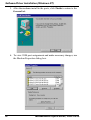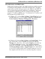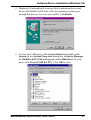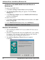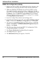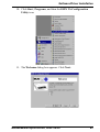
1
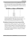
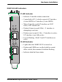
MultiModemISI Hybrid Series Model ISIHP-2S/2U Quick Start Guide MultiModemISI Hybrid SeriesModel ISIHP-2S/2U Quick Start Guide 82093800 Revision A All rights reserved. This publication may not be reproduced, in whole or in part, without prior expressed written permission from Multi-Tech Systems, Inc. All rights reserved. Copyright ' 1999 by Multi-Tech Systems, Inc. Multi-Tech Systems, Inc. makes no representation or warranties with respect to the contents hereof and specifically disclaims any implied warranties of merchantability or fitness for any particular purpose. Furthermore, Multi-Tech Systems, Inc. reserves the right to revise this publication and to make changes from time to time in the content hereof without obligation of Multi-Tech Systems, Inc., to notify any person or organization of such revisions or changes. Record of Revisions Revision Description A Manual released. Preliminary (beta) release 2/19/99. Patents This product is covered by one or more of the following U.S. Patent Numbers: 5.301.274, 5.309.562, 5.355.365, 5.355.653, 5.452.289, 5.453.986. Other patents Pending. Trademarks The Multi-Tech logo is a registered trademark of Multi-Tech Systems, Inc. NetWare is a registered trademark of Novell, Inc. Pentium is a registered trademark of Intel Corporation. SCO is a registered trademark of Santa Cruz Operation, Inc. UNIX is a registered trademark of X/Open Company, Ltd. Windows 95 and Windows NT are registered trademarks of Microsoft. Multi-Tech Systems, Inc. 2205 Woodale Drive Mounds View, Minnesota 55112 (612) 785-3500 or (800) 328-9717 Fax (612) 785-9874 Fax Back (612) 717-5888 BBS (612) 785-3702 or (800) 382-2432 Tech Support (800) 972-2439 Internet Address: http://www.multitech.com Contents Introduction .................................................................................................. 4 Welcome and Product Description ............................................................... 4 Peripiheral Component Interconnect (PCI) .................................................. 5 Introduction ............................................................................................. 6 Computer Requirements .......................................................................... 6 Shipping Contents ................................................................................... 6 Safety Warnings ....................................................................................... 7 Hardware Installation Procedure ............................................................. 8 LED Indicators ...................................................................................... 10 Installing the ISIHP-2S/2U in Windows NT 3.51/4.0 ................................ 12 Installing TAs and Modems to COM Ports in Windows NT ........... 17 I/O Addresses and IRQ Codes .................................................................... 25 Removing ISIHP-2S/2U Card & Driver in Windows NT 3.51/4.0 ............ 26 Installing the ISIHP-2S/2U in Windows 95 and Windows 98 .................... 26 Windows 95 Installation ............................................................................. 26 To Remove the ISIHP-2S/2U Card and Drivers in Windows 95 ................ 28 Windows 98 Installation ............................................................................. 28 To Remove the ISIHP-2S/2U Card & Drivers in Windows 98 .................. 32 Removing the Driver ........................................................................ 32 Installing TAs & Modems to COM Ports in Windows 95 /98 ........ 32 Removing the Driver (Windows 95 only) ........................................ 41 Configuring the Terminal Adapter: Introduction ........................................ 41 North American Users ........................................................................... 41 International Users ........................................................................... 42 Optional Settings ................................................................................... 42 ISDN TA Configuration Utility ............................................................. 44 ConfigMenu Configuration Utility ........................................................ 50 AT Commands ....................................................................................... 51 NetWare Connect (Novell) Driver Installation ........................................... 52 Configuring Ports for NetWare Connect .......................................... 52 Removing the Driver (Novell) ......................................................... 52 SCO Open Server 5 Driver Installation ...................................................... 53 Activating Ports in SCO Open Server 5 ........................................... 56 Removing the Driver (SCO Open Server 5) .................................... 58 Linux Driver Installation ............................................................................ 59 Service ........................................................................................................ 61 Index ........................................................................................................... 62 Introduction W elcome to Multi-Techs new MultiModemISI Hybrid Series, model ISIHP-2S/2U, a multiport hybrid ISDN card that can be plugged into any PCI slot for Remote Access Server (RAS) applications. Included on the ISIHP-2S/2U are four V.90/K56flex central site modems for incoming analog modem and fax calls, as well as two terminal adapters. Each terminal adapter appears as two ports to the server PC using the ISIHP-2S/2U. The terminal adapters identify incoming analog calls and route them to the central site modems. The ISIHP-2S/2U also supports dial-out applications via the modems or terminal adapters. The card features eight RAS ports using two Basic Rate Interface (BRI) ISDN lines. The eight ports allow a server to accept any combination of analog modem and digital ISDN calls, giving the user the flexibility to customize the settings of the terminal adapters and modems. Since the two BRI lines constitute only four Bearer channels, only four of the eight ports can be active at any one time. The two terminal adapters handle the four B-channels as four independent data connections (see diagram below). Com Ports 5 ISDN Modem RJ-45 jack TA 6 Modem 7 Modem 3456 1 2 Line 1 RJ-45 jack Introduction 4 TA 8 Modem 3456 3 4 Line 2 Welcome and Product Description MultiModemISI Hybrid Series, ISIHP-2S/2U Introduction From the perspective of the server PC, the ISIHP-2S/2U is an eightport serial card with eight devices permanently attached to the serial ports. The first four ports are the two terminal adapters, each of which appear as two ports. The remaining four ports are the four central site modems. The following chart summarizes the correlation of ports and devices. Port Number 1 2 3 4 5 6 7 8 Device ISDN Line Number TA TA TA TA Modem Modem Modem Modem 1 1 2 2 1 1 2 2 This Quick Start Guide for the ISIHP-2S/2U contains installation instructions and technical support information to assist you in installing the ISIHP-2S/2U. This guide is written for audiences with basic PC skills; therefore, step-by-step instructions for basic operations such as logging in and file editing are not included. Peripiheral Component Interconnect (PCI) First developed by companies such as IntelTM, AT&TTM and Digital Equipment CorporationTM, the Peripheral Component Interconnect (PCI) bus used by your ISIHP-2S/2U provides high performance and is easy to use. Because PCI devices contain registers with the device information required for configuration, full auto configuration of PCI Local Bus add-in boards and components is supported. Performance factors include a bus data path of 64 bits, clock speeds of 66 MHz, and bandwidth of 264 Mbs. MultiModemISI Hybrid Series, ISIHP-2S/2U 4 Hardware Installation Introduction This section describes how to install the ISIHP-2S/2U server card into the PCI bus on your personal computer, which involves Opening your PC Setting card configuration (determining I/O address DIP-switch setting and IRQ jumper setting) Installing the card into the PC Computer Requirements Pentium-based PC or compatible with PCI bus architecture Microsoft Windows 95, Windows NT version 4.0, SCO Open Server version 5.0, Novell NetWare, or Linux At least one floppy drive 800 blocks of hard disk space for UNIX, 100K bytes for Windows NT, 34K bytes for Windows 95, 50K bytes for Novell Shipping Contents 6 ISIHP-2S/2U card RJ-45 ISDN cord (2) ISIHP Driver Disk set with ISDN TA Configuration Wizard Quick Start Guide MultiModemISI Hybrid Series, ISIHP-2S/2U Hardware Installation Safety Warnings Never install telephone wiring during a lightning storm. Never install telephone jacks in wet locations unless the jacks are specifically designed for wet locations. Never touch uninsulated telephone wires or terminals unless the telephone line has been disconnected at the network interface. Use caution when installing or modifying telephone lines. Avoid using a telephone (other than cordless type) during an electrical storm. There may be a remote risk of electrical shock from lightning. Do not use the telephone to report a gas leak in the vicinity of that leak. Ports that are connected to other apparatus are defined as SELV. To ensure conformity to EN 41003, ensure that these ports are connected only to the same type on the other apparatus. Hardware Installation Procedure 1. Before handling the ISIHP-2S/2U, discharge any static in your body by touching a piece of grounded metal such as the computer chassis. 2. Carefully remove the ISIHP-2S/2U from its antistatic bag, handling it only by the mounting bracket and edges. Do not touch the goldplated connectors along the bottom edge. (You may want to save packaging for possible future use.) 3. Visually inspect the ISIHP-2S/2U. The 2U model is distinct from the 2S model in that it includes auxiliary modules, as shown below. If you have any concerns about the condition of your ISIHP-2S/2U unit, call Technical Support at (612) 717-5863. MultiModemISI Hybrid Series, ISIHP-2S/2U 7 Hardware Installation a Intelligent Serial Interface Hybrid (ISDN/POTS) Cards (Side View) ISIHP-2S International a ISIHP-2U U.S. Domestic 4. To avoid damaging the ISIHP-2S/2U and your PC, make sure your computer and any peripheral equipment connected to it are turned off. The ISIHP-2S/2U can be installed in a Pentium equivalent PCI bus computer. 5. Remove the cover of your computer as instructed in your computers documentation. 6. Locate the unused PCI slot you will be using for your ISIHP-2S/2U card and remove the slot cover according to instructions in your computers documentation. 7. Install the ISIHP-2S/2U card in the selected expansion slot in the same manner as any other add-on card according to your computers documentation. 8 8. Fasten retaining bracket to the computer chassis and replace the cover. 9. Connect the ISIHP-2S/2U to your ISDN telephone wall jack with the provided modular telephone cable. MultiModemISI Hybrid Series, ISIHP-2S/2U Hardware Installation U Interface S Interface NT1 Device S/T Interface ISIHP -2S ISDN line enters building Note: The ISIHP-2S/2U communicates over ISDN lines. If you dont have a standard modular jack near your computer, you should install one or have one installed by your telephone company. In the US, installation kits and adapters are available wherever telephones are sold. Note: The ISIHP-2S requires an S/T-interface. The ISDN phone cord must be connected between the ISDN network connection and the NT1 device. 10. Turn on power to the computer. Now you are ready to install software. MultiModemISI Hybrid Series, ISIHP-2S/2U 9 Hardware Installation LED Indicators The mounting bracket for both the ISIHI-2S and the ISIHI-2U is similar, except the LEDs are labeled differently. Each mounting bracket has two sets of LED indicators that indicate status and line activity. Below, and on the next page, are graphics for each bracket along with descriptions of the LED indicators. ISIHP-2S LED Indicators B1 LED Indicator When lit, indicates active or voice connection on B-channel 1. B2 LED Indicator B1 B2 When lit, indicates active or voice connection on B-channel 2. LINE 1 B1 B2 LINE 2 10 MultiModemISI Hybrid Series, ISIHP-2S/2U Hardware Installation ISIHP-2U LED Indicators P LED Indicator Indicates U interface status connection. Controlled by NT-1, which converts S/T interface (4-wire ISDN) to U interface (2-wire ISDN). D P LINE 1 When U interface and S/T interface are NOT active, LED remains off. Flashes 8 times/second (8 Hz)U interface is attempting to activate. Flashes once/second (1 Hz)U interface is active; S/T interface is not fully active. D P LINE 2 Lit, not flashingBoth U and S/T interfaces are active. D LED Indicator Lights when the ISIHP-2S/2U is turned on. Flashes until SPIDs are verified with the central office switch; then remains lit without flashing. Indicates data link layer status. MultiModemISI Hybrid Series, ISIHP-2S/2U 11 Hardware Installation Installing the ISIHP-2S/2U in Windows NT 3.51/4.0 The following procedure describes how to install the ISIHP-2S/2U in a system operating Microsoft Windows NT 3.51 or 4.0 for use with Remote Access Service (RAS) server and other communications/fax server type applications. These procedures refer to both 3.51 and 4.0. 1. Install the ISIHP-2S/2U in an available PCI slot as described in the installation section of this manual. 2. Turn on the computer. 3. Click Start, Settings, Control Panel, and then double-click Network. In the Network dialog box, click the Adapters tab. Then click Add. 4. The Select Network Adapter dialog box appears. Click Have Disk. 12 MultiModemISI Hybrid Series, ISIHP-2S/2U Software/Driver Installation (Windows NT) 5. The Insert Disk dialog box appears. Insert the MultiModem ISI Driver for Windows NT diskette and click OK. 6. The Select OEM Option dialog box appears. Click OK. MultiModemISI Hybrid Series, ISIHP-2S/2U 13 Software/Driver Installation (Windows NT) A transient dialog box will appear while the setup program is loaded from the diskette to the PC hard drive. 7. The ISI Cards dialog box appears. Click Add. 14 MultiModemISI Hybrid Series, ISIHP-2S/2U Software/Driver Installation (Windows NT) 8. Then this ISI Cards dialog box appears. Select the starting port (usually port 3). 9. The ISI Cards dialog box appears again showing the port assignment. Click Add to add additional cards and repeat step 8. MultiModemISI Hybrid Series, ISIHP-2S/2U 15 Software/Driver Installation (Windows NT) After the last ISIHP/2S/2U card has been added, click Close. 10. The file copies and Multi-Tech ISIHP-2S/2U Adapter appears in the Network Adapters box. Click Close. 11. When this dialog box appears, click Yes to reboot your system. The ISIHP-2S/2U now is installed in Windows NT. 16 MultiModemISI Hybrid Series, ISIHP-2S/2U Software/Driver Installation (Windows NT) Installing TAs and Modems to COM Ports in Windows NT To install terminal adapters: 1. In the Control Panel, double-click the Modems icon. 2. The Modem Properties dialog box appears. Click Add. 3. The Install New Modem dialog box appears. Check the box marked Don't detect my modem; I will select it from a list and click Next. 4. The Install New Modem dialog box appears. Click Have Disk. MultiModemISI Hybrid Series, ISIHP-2S/2U 17 Software/Driver Installation (Windows NT) 5. The Install From Disk dialog box appears. Click OK (diskette should still be in drive). 6. The Install New Modem dialog box appears. From the Models list, select an ISDN protocol (; Auto-Protocol, ML-PPP, PPP, V.120, or X.75, depending on your application). Then click Next. 18 MultiModemISI Hybrid Series, ISIHP-2S/2U Software/Driver Installation (Windows NT) 7. The Install New Modem dialog box appears. Select the ports that correspond to the first four ports of the ISIHP-2S/2U card. Any ports that existed prior to installing the ISIHP-2S/2U appear first in the list of available COM ports. Click Next. The terminal adapters (screen displays modems) install to the selected COM ports. 8. After the terminal adapters install, click Finish to return to the General tab to view COM port assignments (and make changes if necessary). Now you are ready to install the modems. MultiModemISI Hybrid Series, ISIHP-2S/2U 19 Software/Driver Installation (Windows NT) To install modems: 1. In the General tab, click Add. 2. The Install New Modem dialog box appears. Check the box marked Don't detect my modem; I will select it from a list. Then click Next. 20 MultiModemISI Hybrid Series, ISIHP-2S/2U Software/Driver Installation (Windows NT) 3. The Install New Modem dialog box appears. From the Models list, select Central Site Modems for the modems. Then click Next. 4. Select the ports that correspond to the last four ports of the ISIHP2S/2U card. Click Next. The modems install to the selected COM ports. MultiModemISI Hybrid Series, ISIHP-2S/2U 21 Software/Driver Installation (Windows NT) 5. After the modems install to the ports, click Finish to return to the General tab. 6. To view COM port assignments and make necessary changes, use the Modem Properties dialog box. 22 MultiModemISI Hybrid Series, ISIHP-2S/2U Software/Driver Installation (Windows 95) 7. Close the Modems Properties dialog box. The message below appears asking if you want to configure dial-up networking. Click Yes. 8. The Remote Access Setup dialog box appears. Click Add. 9. Each COM port appears in a separate Add RAS Device dialog box. To add the highlighted device, click OK. 10. The Remote Access Setup dialog box displays again. Repeat steps 7 and 8 until all devices are added. MultiModemISI Hybrid Series, ISIHP-2S/2U 23 Software/Driver Installation (Windows 95) 11. When all devices have been added, click Continue. 12. After the bindings have been reviewed and stored, the message below appears, click Yes. After re-booting, the ISI Cards icon appears in the Control Panel. icon You are now ready to configure the terminal adapter. See the section,Configuring the Terminal Adapter, on page 45. 24 MultiModemISI Hybrid Series, ISIHP-2S/2U Software/Driver Installation (Windows 95) I/O Addresses and IRQ Codes Unlike many modem products, the ISIHP-2S/2U has no DIP switch for I/O addresses and no jumper to determine the IRQ code. The input/ output address and the interrupt request code (IRQ) for the ISIHP-2S/ 2U are assigned automatically during driver installation. During any subsequent re-cofiguring of your PC, you may need to know the assigned I/O address andIRQ code. To determine the I/O address and IRQ assigned to the ISIHP-2S/2U: (for Windows NT) click on Start, Settings, Control Panel and select the ISI Cards icon; or click on Start, Programs, Administrative Tools (Common), Windows NT Diagnostics, Resources; (for Windows 95) click on Start, Settings, and Control Panel. From the Control Panel, click on System icon and then the Device Manager tab. From there, click on the Computer icon at the top of the Device Manager window. The Computer Properties dialog box will appear. In the View Resources tab, click on either the Interrupt Request (IRQ) or Input/Output (I/O) radio buttons to view lists of both the IRQs and I/O memory addresses in use in the computer and what devices are currently using these resources. MultiModemISI Hybrid Series, ISIHP-2S/2U 25 Software/Driver Installation (Windows 95) Removing ISIHP-2S/2U Card and Driver in Windows NT 3.51/4.0 1. Click Start, Settings, Control Panel, and then double-click Network. 2. The Network dialog box appears. Click the Adapters tab. 3. Select Multi-Tech PCI ISI Card, and then click Remove. Note: To complete an uninstall, reboot your system. Installing the ISIHP-2S/2U in Windows 95 and Windows 98 This section describes how to install the ISIHP-2S/2U in systems operating Microsoft Windows 95 or Windows 98 to use with a Remote Access Service (RAS) server and other communications/fax server type applications. Windows 95 Installation 1. After installing the ISIHP-2S/2U in an available PCI slot, turn on the computer. 2. Windows 95 automatically detects the ISIHP-2S/2U card. A dialog box appears with a message stating that Windows has found the new hardware and is locating the software for it. 3. The Update Device Driver dialog box appears. Insert the ISIHP2S/2U Windows 95 driver diskette and click Next. 26 MultiModemISI Hybrid Series, ISIHP-2S/2U Software/Driver Installation (Windows 95) 4. Windows 95 automatically searches for the unknown device and locates the MultiTech ISI Port. After the operating system goes through this process for every port added, click Finish. 5. To view the COM ports, click Control Panel and double-click System. In the System Properties dialog box in Device Manager, the MultiTech PC ISI Card appears under Multi Port. To view ports, click Ports (COM & LPT). Click OK to close. MultiModemISI Hybrid Series, ISIHP-2S/2U 27 Software/Driver Installation (Windows 95) To Remove the ISIHP-2S/2U Card and Drivers in Windows 95 To remove the ISIHP-2S/2U: 1. Click Start, Settings, Control Panel, and then System. 2. The System Properties dialog box appears. Click the Device Manager tab. 3. Click Multi Port Adapter and select MultiTech PCI ISI Card, and then click Remove. To remove the drivers: 1. Click Start, Settings, Control Panel, and then double-click Add/ Remove Programs. 2. Select MultiTech ISI Card and then click Add/Remove. Note: To complete an uninstall, reboot your system. Windows 98 Installation 1. After installing the ISIHP-2S/2U in an available PCI slot, turn on the computer. 2. Windows 98 automatically detects the ISIHP-2S/2U card. A dialog box appears with a message stating that Windows has found the new hardware and is locating the software for it. 3. The Add New Hardware Wizard dialog box appears. Click Next. 28 MultiModemISI Hybrid Series, ISIHP-2S/2U Software/Driver Installation (Windows 95) 4. In the next Wizard dialog box, select Search for the best driver for your device. (Recommended). Then click Next. 5. In the next Wizard dialog box, make sure Floppy disk drives is checked. Insert the MultiModem ISI Driver for Windows 95/98 diskette. Then click Next and the system locates the file. MultiModemISI Hybrid Series, ISIHP-2S/2U 29 Software/Driver Installation (Windows 95) 6. When this Wizard dialog box appears, click Next. 7. Windows then installs the device driver for the ISIHP-2S/2U card. When this dialog box appears, click Finish. Windows 98 will now detect and create 8 COM ports. 8. After the COM parts have been created, you must re-boot your PC (remove the diskette from the floppy drive before re-booting). 30 MultiModemISI Hybrid Series, ISIHP-2S/2U Software/Driver Installation (Windows 95) 9. To view the COM ports, click Control Panel and double-click System. The System Properties dialog box appears. The MultiTech PCI ISI Card is located under Multi Port Adapter. Click Ports (COM & LPT) to view the ports. Click OK to close. MultiModemISI Hybrid Series, ISIHP-2S/2U 31 Software/Driver Installation (Windows 95) To Remove the ISIHP-2S/2U Card and Drivers in Windows 98 To remove the ISIHP-2S/2U card: 1. Re-boot your computer. 2. Click Start, Settings, Control Panel, and then System. 3. The System Properties dialog box appears . Click the Device Manager tab. 4. Click Multi Port Adapter and select MultiTech ISIHP-2S/2U 2BRI/4 56K Hybrid Card. Then click Remove. To remove the drivers: 1. Click Start, Settings, Control Panel, and then double-click Add/ Remove Programs. 2. Select MultiTech ISI Card and then click Add/Remove. Removing the Driver 1. Click Settings, Control Panel; then double-click Add/Remove Programs. 2. From the list box, select ISICOM Driver. 3. Click Add/Remove and follow dialog box instructions. Installing TAs & Modems to COM Ports in Windows 95 /98 To install terminal adapters: 1. Click Start, Settings, Control Panel, and then double-click the Modems icon. 2. If no modems are currently installed, the Install New Modem dialog box appears. Check the box marked Don't detect my modem; I will select it from a list. Then click Next. If other modemshave been installed, the Modems Properties dialog box will appear. 32 MultiModemISI Hybrid Series, ISIHP-2S/2U Software/Driver Installation (Windows 95) Click Add and the Install New Modem dialog box will appear. Check the box marked Don't detect my modem; I will select it from a list. Then click Next. MultiModemISI Hybrid Series, ISIHP-2S/2U 33 Software/Driver Installation (Windows 95) 3. The Install New Modem dialog box appears. Insert diskette labeled MultiModem ISI Driver for Windows 95 & Netware AIO and click Have Disk. 4. The Install From Disk dialog box appears. Click OK. 5. The Install New Modem dialog box appears. Select a protocol (depending on your application) from the Models list; then click Next. 34 MultiModemISI Hybrid Series, ISIHP-2S/2U Software/Driver Installation (Windows 95) 6. The Install New Modem dialog box appears. Select the port that corresponds to the lowest numbered port of the ISIHP-2S/2U card. Any ports that had been installed before installing the ISIHP-2S/2U card are numbered lower than the ports of the ISIHP-2S/2U card. Click Next. 7. Windows will install the first terminal adapter. Click Next. MultiModemISI Hybrid Series, ISIHP-2S/2U 35 Software/Driver Installation (Windows 95) 8. After the terminal adapter installs, click Finish to return to the General tab to view COM port assignments (and make changes if necessary). 9. 36 Click Add and repeat installation steps 28 to install terminal adapters to the first four ports of the ISIHP-2S/2U. After the terminal adaptershave been installed, you are ready to install the modems. MultiModemISI Hybrid Series, ISIHP-2S/2U Software/Driver Installation (Windows 95) To install modems (Windows 95/98): 1. In the General tab, click Add. 2. The Install New Modem dialog box appears. Check the box marked Don't detect my modem; I will select it from a list. Then click Next. MultiModemISI Hybrid Series, ISIHP-2S/2U 37 Software/Driver Installation 3. The Install New Modem dialog box appears. Insert the driver diskette labeled MultiModem ISI Driver for Windows NT. Then click Have Disk. 4. The Install from Disk dialog box appears. Click OK. 5. The Install New Modem dialog box appears. From the Models list, select Central Site Modems for the modems. Then click Next. 38 MultiModemISI Hybrid Series, ISIHP-2S/2U Software/Driver Installation 6. The Install New Modem dialog box appears. Select the numbered port (the fourth highest number) of the ISIHP-2S/2U card. Click Next. The modem installs to the COM port. 7. After the modem installs to the port, click Finish. MultiModemISI Hybrid Series, ISIHP-2S/2U 39 Software/Driver Installation 8. Return to the General tab to view COM port assignments (and make changes if necessary). 9. Click Add and repeat installation steps 28 to install modems to the last three ports of the ISIHP-2S/2U. Now you are ready to configure the terminal adapters. 40 MultiModemISI Hybrid Series, ISIHP-2S/2U Software/Driver Installation Removing the Driver (Windows 95 only) 1. Click Settings, Control Panel, and then double-click Add/ Remove Programs. 2. From the list box, select ISICOM Driver. 3. Click Add/Remove and follow screen instructions. Configuring the Terminal Adapter Introduction North American users must configure the terminal adapter to match network switch type, the service profile identifier (SPID), and the directory number (DN). For international users, the terminal adapter ships already configured for NET3, which should work on most phone lines in Europe. However, you may want to customize settings, regardless of your location. (See Optional Settings on the following page.) You can configure the terminal adapters with the ISDN TA Configuration utility, ConfigMenu, or with AT commands. Instructions for all three are provided in this section. ISDN TA Configuration Utilityrecommended for computers with Windows 95/98 and Windows NT. ConfigMenurecommended for computers with DOS or Windows 3.x and a VT100/ANSI compatible terminal or data communication program that includes VT100/ANSI terminal emulation. AT Commandsallow you to fine tune TA operation with AT commands and S-registers. Enter these commands in your data communication programs terminal mode. AT commands are described in detail in the online manual. North American Users Before you connect the ISIHP-2S/2U to your network terminator, you must configure it to match the following: Network Switch Type ____________________ Select the network switch type your ISDN service uses at its local central office. You can set the TA to NET3, AT&T 5ESS, NT DMS- MultiModemISI Hybrid Series, ISIHP-2S/2U 41 Software/Driver Installation 100, or US National ISDN-1. If you don't know the switch type, get the information from the local phone company. AT command: !CO= SPIDs and DNs ________________________ The TA must be configured with the Service Profile Identifier (SPID). The SPID, assigned by the local phone company, is for the specific BRI line where TA is attached. The SPID field is empty prior to configuration. AT command: AT!C6= and AT*!C6 The Directory Number (DN) is the phone number another user would call to contact this TA once it is attached to the ISDN. AT commands: AT!N1= and AT*!N1= Note: SPIDs only apply for North American switch types. International Users The terminal adapters ship already configured for NET3, which should work for most telephone lines in Europe. If you want to customize settings, refer to the Optional Settings below. Optional Settings Data TEI _____________________________ The Data TEI is the TEI (terminal endpoint identifier) assigned to the data channel. You can select Auto TEI, a fixed TEI, or Disable. A TEI is a number used by the central office switch to uniquely identify each device that is connected to the network. When it uses dynamic TEI assignments (Auto TEI), the central office switch assigns a TEI each time the TA connects to the network. However, the ISDN service provider may assign a fixed TEI at subscription time, in which case you must configure the TA with the fixed TEI number. You also can disable the channel, which may be useful when multiple TAs are attached to a network terminator bus. AT command: !D3= Voice TEI _____________________________ The Voice TEI is the TEI assigned to the voice channel. You have the same choices as for Data TEI: Auto TEI, fixed TEI number, or Disable. AT command: *!D3= Persistent DTR Dialing __________________ 42 MultiModemISI Hybrid Series, ISIHP-2S/2U Software/Driver Installation A high DTR (Data Terminal Ready) signal on the serial port indicates that your computer or terminal is ready to communicate with your TA. DTR normally goes high when a communication program starts or is ready to dial. Persistent DTR dialing enables the TA to automatically redial the number stored in memory location 0 whenever DTR is high, and the serial port does not have an active call. You can enable or disable this feature. AT command: $D Auto Answer Data Calls _________ Rings to Answer _________ Select Auto Answer if you want the TA to automatically answer all incoming data calls (option does not affect analog port). The Rings to Answer number (range: 1255) selects number of rings the TA waits before answering an incoming call. Default: 1 ring. AT command: S0= Dialing Method ________________________ Select either the Enbloc or the Overlap dialing method for use when establishing a data call. Your ISDN provider determines the dialing method. The enbloc method is used for most ISDN dialing; however, you can select the overlap method if you are working with a private network. AT command: %A97= Data Protocol _________________________ The data protocol, also known as the B-channel protocol and the rate adaption protocol, is the language spoken over each 64 Kbps channel between two ISDN devices. The devices on both ends of the ISDN link must use identical protocols. AT command: !Z V.120 Protocolprovides rates up to 64000 bps on each B channel. PPP Protocolprovides rates up to 64 Kbps per channel. Stored Numbers ________________________ The TA can optionally store as many as 10 phone numbers, up to 20 characters each. AT command: &Z= Dialing Stored Numbers _________________ The TA can dial a number previously stored in directory number n using the &Zn=x command. AT command: e.g., DS3 MultiModemISI Hybrid Series, ISIHP-2S/2U 43 Software/Driver Installation ISDN TA Configuration Utility 1. Before you start the ISDN TA Configuration utility, disconnect the ISIHP-2S/2U by removing the RJ-45 cable from the ISDN jack. 2. Make sure Windows NT Remote Access Service (RAS), or any other application that is using the modem, is shut down. To shut down RAS, click Start, Programs, and then Administrative Tools (Common). Then click Remote Access Admin and click Server, which will indicate whether or not RAS is running. If it is running, click Stop Remote Access Service. 3. Insert the Config Utility diskette into the floppy drive. 4. From the main desktop of your PC, select Start, Settings, Control Panel. Click on the Add/Remove Programs icon. Click Install. 5. The dialog box Install Program from Floppy Disk or CD-ROM appears. Click Next. The Run Installation Program dialog box appears. Click Finish. 6. The Welcome dialog box for the ISDN TA Configuration Utility Setup program appears. Click Next. 7. The Choose Destination Location dialog box appears. 8. The Setup dialog box appears. 9. The Information dialog box appears. Click OK. 44 MultiModemISI Hybrid Series, ISIHP-2S/2U Software/Driver Installation 10. Click Start, Programs, and then the ISDN TA Configuration Utility icon. 11. The Welcome dialog box appears. Click Next. MultiModemISI Hybrid Series, ISIHP-2S/2U 45 Software/Driver Installation 12. The Searching for TA dialog box appears. Click Next. The next dialog box specifies the TA that has been identified. 46 MultiModemISI Hybrid Series, ISIHP-2S/2U Software/Driver Installation 13. The Configuration dialog box appears. If you have questions about choices, click Help. After entering information in each dialog box, click Next. 14.The SPID dialog box appears (North America only). Referring to your network configuration notes, enter the appropriate information; then click Next. MultiModemISI Hybrid Series, ISIHP-2S/2U 47 Software/Driver Installation 15. The Data Protocol Setup dialog box appears. Referring to your network configuration notes, enter the appropriate information; then click Next. 16. In the Save Configuration dialog box, enter a name to store the configuration. Then click Next. 48 MultiModemISI Hybrid Series, ISIHP-2S/2U Software/Driver Installation 17. To load the configuration, click Next in the Load Configuration dialog box. 18. Then click Finish in the Configured dialog box. 19. The first TA now is configured. Click Back to return to the Configuration dialog box and repeat steps 5 through 10 to configure the remaining TA(s). If you install multiple ISIHP-2S/2U in the same PC, you must configure two TAs per card installed. For example, if you install four ISIHP-2S/2U cards in one PC, you have to configure eight TAs (two per card). 20. After both TAs are configured, close the ISDN TA Configuration utility and connect the to the network again. MultiModemISI Hybrid Series, ISIHP-2S/2U 49 Software/Driver Installation ConfigMenu Configuration Utility Use the ConfigMenu configuration utility with computers using DOS or Windows 3.x operating systems. ConfigMenu is installed in the TAs as part of the firmware. To use ConfigMenu: 1. Start a data communication program and select the COM port where the TA is connected. 2. In the communication program dialog box, type AT@CONFIG and press ENTER. ConfigMenus Main Menu appears (see screen below). 3. To select menu item, type its number and press ENTER. A submenu then appears where you can make selections. At the lowest level, you can change a configuration option by selecting a number or typing a value and pressing ENTER. 4. When you finish, close ConfigMenu. 5. Use the &W command to save your new configuration and to load it automatically when the TA is turned on. 50 MultiModemISI Hybrid Series, ISIHP-2S/2U Software/Driver Installation ConfigMenu Menus Network Configuration Menuconfigures network parameters such as switch type, data and voice TEIs, and data and voice MSNs. When you finish, select Save Network Configuration to save your work. Call Control Configuration Menuchanges how the TA originates and answers calls. Options include Auto Answer, Rings to Answer, Dialing Method, and Persistent DTR Dialing. Data Protocol Menuchanges rate adaption protocol used by the TA. Stored Numbers Menustores up to ten phone numbers ( maximum of 20 characters each). Stored number 0 is the phone number that will be dialed if persistent DTR dialing is enabled. Port Control Configuration Menuconfigures TAs serial port, including how TA responds to control signals on the serial interface. Help Menuprovides assistance in navigating through the TA menu system or viewing the ISIHP-2S/2Us firmware version numbers. AT Commands You can configure the terminal adapters using AT commands, just as you would configure an analog modem. Use this method if you prefer to work with AT commands or if you have a special requirement not addressed by either of the configuration utilities. To configure the TAs with AT commands: 1. Disconnect the ISIHP-2S/2U from the network (remove RJ-45 cables from ISDN jacks). 2. Start a data communication program and select the first and third COM ports to be configured. 3. Referring to records made for your system, enter AT commands in the terminal window of the data communications program. 4. When you finish, use the &W command to save your new configuration and to select it to load automatically when the ISIHP2S/2U is turned on. 5. Close the data communications program and reconnect the TA to the network terminator. For more information, see the online Owners Manual. MultiModemISI Hybrid Series, ISIHP-2S/2U 51 Software/Driver Installation NetWare Connect (Novell) Driver Installation Multi-Tech Systems provides AIO drivers for the ISIHP-2S/2U, so it can function with Novell compatible asynchronous applications (e.g., NetWare Connect). The AIO driver is simply an NLM (NetWare Loadable Module) that runs on the file server. Drivers must be loaded on the file server where the board is installed. Drivers can be loaded from the file servers console prompt or incorporated for autoloading in the AUTOEXEC.NCF file. To install the Multi-Tech AIO driver, copy the file AIOISIX.NLM to the system directory of the file server from a workstation on the network. To copy, you can use the following command: COPY A:\NOVELL\AIOISIX.NLM F:\SYSTEM To load the driver, go to the system or PC console (where the ISIHP2S/2U is installed) and enter the following at the prompt: LOAD AIOISIX [port=W] [int=X] [name=Y] [note=Z] To install the ISIHP scripts, copy aiomdms.mdc to f:\system\aio\directory. Click Yes to overwrite the existing aiomdms.mdc file. Configuring Ports for NetWare Connect To set up NetWare Connect ports, enter LOAD NWCCON at the NetWare console prompt. LOAD NWCCON opens the NetWare Connect Configuration Utility. Select the appropriate menu options (modem type, speed, flow control, etc.) Removing the Driver (Novell) In Novell, remove file AIOISIX.NLM from the system directory and make the appropriate changes to the Autoexec.ncf file. 52 MultiModemISI Hybrid Series, ISIHP-2S/2U Software/Driver Installation SCO Open Server 5 Driver Installation The installation utility provided by SCO is called custom. This section provides a brief guide for opening the utility and installing the driver. The instructions below should be used only on SCO Open Server 5 systems. When you have completed the steps below, go to Multi-Tech Installation Script, which immediately follows this section. 1. If installing the driver from your default floppy drive, type custom and press ENTER to open the custom utility. If using a nondefault drive, you must inform your system of the disk drive from where you are doing the installation and the size and capacity of the diskette(s). 2. Select Software and press ENTER. 3. The main menu displays a list of options. Press ENTER to select the highlighted item (default): Install. 4. Select From comsco and press ENTER. 5. Make sure the driver diskette is in the floppy diskette drive and then press ENTER to select the highlighted item (default): Floppy Disk Drive 0. The following message appears: Examining media. Please wait 6. The system recognizes you are installing the Multi-Tech Serial Card Driver and prompts you to select the type of installation. 7. Select Full Installation and press ENTER to continue. The following messages appear: Extracting Files... Executing Multi-Tech Serial Card Driver Init Script... 8. When installation finishes, this prompt appears: Do you wish to continue ( y / n / q ):? Type Y and press ENTER. Proceed with the next section, MultiTech Installation Script. MultiModemISI Hybrid Series, ISIHP-2S/2U 53 Software/Driver Installation This section guides you through the Multi-Tech Installation Script for SCO and UNIXWare systems. The script requests information such as how many boards you want to install, what I/O address and IRQ values (interrupt requests) you have selected, and how many pseudo devices you want to create for Multi_View utility. This information extracts the necessary drivers, which will be linked with your systems kernel. 1. The first screen requests the number of ISIHP-2S/2U cards you are installing. If installing more than one ISIHP-2S/2U, use the chart on page 7 of this guideRecommended Base I/O Address and IRQ Valuesto enter the appropriate values for each card. Enter the number of cards and press ENTER. 2. The second screen requests the number of ports. Enter 8 and press ENTER. 3. The third screen requests the base I/O address you selected for the first card you are installing. It is important to verify that the address you select for each ISI does not overlap with existing devices or with another ISI. The ISI card uses the base I/O address and the next fifteen addresses. Note: If the I/O address you select conflicts with an existing device in your system, you must remove the ISI driver and reinstall it. Enter the base I/O address and press ENTER. For additional information, refer to the online manual. 4. The fourth screen requests the IRQ value for this card. Verify that the IRQ you select for each ISI does not overlap with existing devices or with another ISI. Type the desired IRQ value and press ENTER. Note: If you entered a number greater than 1 at the first screen, the previous three screens reappear in sequence for each card you install. After you enter the necessary information, installation continues. 54 MultiModemISI Hybrid Series, ISIHP-2S/2U Warranty and Service Information 5. The fifth screen requests you to enter the number of pseudo devices to create for Multi_View Utility. Enter the value and press ENTER. Note: You must enter a minimum of 8 for each board installed. 6. The /dev directory holds device-information files used by the kernel to access the hardware. When you add an ISI card, you must give the ISI ports unique names, so they do not conflict with existing ports or other devices known to your system. If you use an existing device name to identify your new ISI ports, the existing device is deleted when the ISI port using its name is created. The default base name for ISIHP-2S/2U ports is ttyl. The default base name for printer ports is prnl. If this is acceptable, type Y and press ENTER. To change the base name, type N and provide a prefix of less than five characters. The base name you select will be used for all ports on each card you install. The following describes the format used in naming ISI ports: Default device name and format: ttyl ttyl BASENAME This prefix is applied to all ISI ports on all boards. Base names contain 14 characters. b BOARD NUMBER Values of 1 through 4, depending on the number of cards installed. x PORT LETTER Values of AH for ISI ports. (SCO UNIX values AH indicate modem ports.) Device base name selected: _________________ 7. After you select a device base name, you are prompted for a printer base name. This prefix identifies each port that supports a terminal with a printer attached to its auxiliary port (for transparent printing). Select a unique base name or accept the default of prnl (printer parameters are outlined in the Multi_Setup Utility section in this guide). Printer base name selected: _________________ MultiModemISI Hybrid Series, ISIHP-2S/2U 55 Software/Driver Installation 8. The Multi_View utility initializes the multiple-page capability of terminals with multiple pages of memory. You are asked how many pseudo devices (the total number of pseudo devices you want to make available to the Multi_View utility) to create. This is the total number of devices available to all Multi-Techs terminals. You can have a maximum of 256 pseudo devices in your system. 9. The confirmation screen lists the values you selected. If these values are correct, type Y and the installation process continues. If there is an error in any of the values displayed, type N and the first screen displays. Then reenter the information for each card. When you accept the confirmation list (by typing Y), a series of messages displays while the driver is being installed and the kernel rebuilt. When the display finishes, press ENTER to continue. When Installation complete displays, press ENTER . 10. Select Host and press ENTER. Remove the diskette from the drive. 11. Select Exit and press ENTER. 12. To reboot the system, enter the following commands: Type sync and press ENTER. Type sync again and press ENTER. Type haltsys and press ENTER. Driver installation for the ISIHP-2S/2U card now is complete. Activating Ports in SCO Open Server 5 SCO Open Server 5 provides a device database that monitors the activity of serial ports through which users can log onto the host. If your ISI ports are used by terminals (e.g., to allow users to log onto your host), you must create an entry in the systems device database that furnishes specific information for the terminals that will be used on each ISI port. The database is referenced each time a user attempts to log in. If there is no database entry for a particular terminal, access to the host is denied. 1. Turn on your system, noting that the firmware for each ISIHP-2S/ 2U loads successfully. If the firmware for a given ISIHP card does not load, none of its ports will be accessible. (If this happens, see 56 MultiModemISI Hybrid Series, ISIHP-2S/2U Software/Driver Installation Multi-Techs Administrative Utility section in the online manual.) 2. The device database can be modified in two ways: To create terminal accounts with default settings, type /tcb/bin/ ttys_update. To customize terminal entries, you must create them individually by entering the system administrators shell (you must be logged in as the root user). To enter the administrators shell, type sysadmsh and press ENTER. 3. Create device entries for each port of the ISI card by selecting the following from the database menu: Accounts, Terminal, Create. 4. Type the complete name of the first device you want to create, substituting the base name, board number, and port letter for the parameters: ttylb. Use a lower case x value for local DTE (terminal) support and an upper case X value for modem control for each port you want to enable. The port status can be altered later, but one setting must be selected at this time. 5. Repeat this process for each port on each board you have installed. Record the setting you select for each port. 6. Using device names created in the previous section, type the following command for each port you want to activate: enable ttylbx 7. Repeat this command for each port you want to activate, using the lower case letter for local terminal use or upper case for modem control. Note: Only one of the options (e.g., modem control or local terminal access) should be enabled for any port at one time. For example, you cannot enable ttyl1a and then enable ttyl1A. To change the status of a port, disable the current status (disable ttyl1a) and then enable it for the desired status (enable ttyl1A). MultiModemISI Hybrid Series, ISIHP-2S/2U 57 Software/Driver Installation Removing the Driver (SCO Open Server 5) To remove the Multi-Tech Serial Card Driver, enter the configuration utility (e.g., custom for SCO Open Server 5) and follow instructions to remove the entire driver and rebuild the kernel without the ISI driver. If it is necessary to reinstall the driver due to I/O address or IRQ overlap, remove the driver first. 58 MultiModemISI Hybrid Series, ISIHP-2S/2U Software/Driver Installation Linux Driver Installation To install the Linux driver: 1. Insert the driver installation diskette. 2. Prepare a temporary installation directory: mkdir isicom 3. Change your current directory to the temporary installation directory: cd \isicom 4. Place the file isicom.tar into the isicom directory. 5. Then extract the file using the tar utility: tar xvf /isicom/isicom.tar 6. Make sure the following are installed on your system: the make utility, the GNU C compiler (gcc), and kernel sources. 7. Run the bash Install script to compile the driver as a loadable module and to compile the user space firmware loader. 8. The files are copied to the destination folder. If you dont specify the folder, the destination folder default is /usr/local/ISICOM (case sensitive). This also creates device files for the ISI cards, normal and callout ports, in the /dev folder. 9. To load the driver manually, use the ISIHP-2S/2U installation configuration stored in the ISICOMStart file in the destination folder. Or, you can include the configuration in the appropriate start-up script stored in the /etc/rc.d/ folder, so it loads when you start the computer. 10. If you make any changes to this configuration, edit the first line of the ISICOMSTART file. The correct syntax for this line is as follows: insmod <destination folder>isicom.o ISIBase1=0xXXXX Irq1=XX ISIBase2=0xXXXX Irq2=XX ISIBasex and Irqx represent the base I/O address and IRQ that are passed to the driver at module loading time. Refer to the insmod manual page for more details on parameter passing. MultiModemISI Hybrid Series, ISIHP-2S/2U 59 Software/Driver Installation Note: A base I/O address of 0, e.g., ISIBaseX=oxo, or omission of these parameters for any card X, disables that particular card. Miscellaneous: Device files corresponding to ports on the ISIHP-2S cards are created in the /dev folder. Use ttyMxy for normal ports and cumxy for corresponding callout ports. The letter x is the card number (14), and y is the port number, (ap) for 16-port cards. Normal ports (ttyM) are configured for dial-in connections. Callout ports (cum) are used for dial-out connections. To view busy I/O address space on your system, enter: cat /proc/ioports To view busy IRQs, enter: cat /proc/interrupts To load the driver manually, use insmod. Example: To load two ISI cards configured with base I/O addresses 0x210 and 0x200 and IRQs 5 and 10, enter the following in the destination folder: insmod isicom ISIBase1=0x210 Irq1=5 ISIBase2=0x200 Irq2=10 To remove the driver manually, enter rmmod isicom. This removes the driver only if no ISI ports are in use. 60 MultiModemISI Hybrid Series, ISIHP-2S/2U Software/Driver Installation Limited Warranty Multi-Tech Systems, Inc. (MTS) warrants that its products will be free from defects in material or workmanship for a period of two years from the date of purchase, or if proof of purchase is not provided, two years from date of shipment. MTS MAKES NO OTHER WARRANTY, EXPRESSED OR IMPLIED, AND ALL IMPLIED WARRANTIES OF MERCHANTABILITY AND FITNESS FOR A PARTICULAR PURPOSE ARE HEREBY DISCLAIMED. This warranty does not apply to any products which have been damaged by lightning storms, water, or power surges or which have been neglected, altered, abused, used for a purpose other than the one for which they were manufactured, repaired by the customer or any party without MTSs written authorization, or used in any manner inconsistent with MTSs instructions. MTSs entire obligation under this warranty shall be limited (at MTSs option) to repair or replacement of any products which prove to be defective within the warranty period, or, at MTSs option, issuance of a refund of the purchase price. Defective products must be returned by Customer to MTSs factory transportation prepaid. MTS WILL NOT BE LIABLE FOR CONSEQUENTIAL DAMAGES AND UNDER NO CIRCUMSTANCES WILL ITS LIABILITY EXCEED THE PURCHASE PRICE FOR DEFECTIVE PRODUCTS. Service Multi-Tech has an excellent technical support staff available to help you get the most out of your Multi-Tech product. If you have any questions about the operation of this product, call Technical Support at (800) 972-2439. Model and serial numbers are located on the Multi-Tech label on the component side of the ISIHP-2S/2U. To display the firmware version, type ATI1 in terminal mode. Software versions are printed on the diskette labels. Before calling Technical Support, note the status of your equipment, including screen messages, diagnostic test results, problems with a specific application, etc. MultiModemISI Hybrid Series, ISIHP-2S/2U 61 Index Index A AT commands 41 B Basic Rate Interface (BRI) 4 C ConfigMenu 41 Call Control Configuration Menu 51 Data Protocol Menu 51 Help Menu 51 menus 51 Network Configuration Menu 51 Port Control Configuration Menu 51 Stored Numbers Menu 51 configuration AT commands 41, 51 ConfigMenu 41, 50 ISDN Configuraiton Utility 44 ISDN Configuration Utility 41 ports in Netware Connect 52 connecting to ISDN wall jack 8 Contents, package 5 H hardware computer requirements 6 installation 7 hardware installation introduction 6 I installation activating ports in SCO Open Server 5 56 hardware 7 62 modems to COM ports in Windows 95 37 in Windows NT 20 software/drivers in SCO Open Server 5 53 Linux 59 NetWare Connect 52 terminal adapters to COM ports in Windows 95 32 in Windows NT 17 to COM ports in Windows NT 17 installing software/driver in Windows 95 26 in Windows 98 28 in Windows NT 12 ISDN Configuration Utility 41 ISDN line 5 L LED indicators 10 M mounting bracket 10 MultiModemISI Hybrid Series introduction 4 N naming ports 55 Netware Connect (Novell) 52 P package contents 5 R Remote Access Server (RAS) 4 removing software/driver NetWare Connect (Novell) 52 software/drivers MultiModemISI Hybrid Series, ISIHP-2S/2U in SCO Open Server 5 58 removing driver in Windows NT 32 removing software/driver in Windows 95 28 in Windows 98 32 in Windows NT 26 S S/T interface 11 safety warnings 7 SCO Open Server 5 53 service 61 shipping contents 6 software/driver installation in Windows 95 26 in Windows 98 28 in Windows NT 12 T terminal adapter configuring 41 U U interface 11 W warranty 61