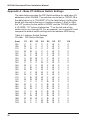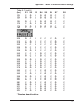
1
Models ISI3334/4 ISI3334/8 Intelligent Serial Interface Card with Integrated Data/Fax Modems Hardware/Driver Installation Manual Owner's Manual P/N 82062600 Revision A MultiModemISI (Hardware and Driver Installation) This publication may not be reproduced, in whole or in part, without prior expressed written permission from Multi-Tech Systems, Inc. All rights reserved. Copyright © 1997 by Multi-Tech Systems, Inc. Multi-Tech Systems, Inc., makes no representation or warranties with respect to the contents hereof and specifically disclaims any implied warranties of merchantability or fitness for any particular purpose. Furthermore, Multi-Tech Systems, Inc., reserves the right to revise this publication and to make changes from time to time in the content hereof without obligation of Multi-Tech Systems, Inc., to notify any person or organization of such revisions or changes. Record of Revision Revision A (1/20/97) Description Manual released at Revision A. TRADEMARKS Trademarks of Multi-Tech Systems, Inc. are as follows: Multi-Tech, MultiModemISI, MultiExpress, and the Multi-Tech logo: Multi-Tech Systems, Inc. UNIX: X/Open Co. Ltd. SCO: The Santa Cruz Operation, Inc. Pentium: Intel Corporation PC-DOS: International Business Machines Corporation Novell, NetWare, NetWare Connect and UNIXWare: Novell Corporation Xenix: Xerox Corporation Windows® and WindowsNT® are registered trademarks of Microsoft All brand names mentioned in this publication are trademarks or registered trademarks of their respective companies. Multi-Tech Systems, Inc. 2205 Woodale Drive Mounds View, Minnesota 55112 U.S.A. (612) 785-3500 or (800) 328-9717 U. S. FAX 612-785-9874 Fax-Back Service 612-717-5888 Technical Support (800) 972-2439 BBS (612) 785-3702 or (800) 392-2432 Internet Address: http://www.multitech.com Technical Writer: [email protected] Contents Chapter 1 - Introduction and Description 1.1 1.2 1.3 1.4 Introduction to the IntelligentSerialInterface .................................. 6 Product Description ....................................................................... 6 How to Use This Manual ................................................................ 7 Technical Specifications ................................................................ 8 Chapter 2 - Hardware Installation 2.1 2.2 2.3 2.4 Safety Warnings .......................................................................... 12 MultiModemISI Installation ........................................................... 12 Determining Current System Settings ......................................... 13 Hardware Installation Procedure ................................................. 14 Chapter 3 - MultiModemISI Driver Installation 3.1 3.2 3.3 3.4 3.5 3.6 3.7 3.8 3.9 Introduction .................................................................................. 20 Installing the ISI Driver in Windows NT ....................................... 20 3.2.1 Removing the ISI Drivers in Windows NT 3.51 ............... 22 3.2.2 Removing the ISI Drivers in Windows NT 4.0 ................. 23 Installing the ISI Driver in Windows 95 ........................................ 23 3.3.1 Removing the ISI Drivers in Windows 95 ....................... 26 Installation in SCO Open Server 5 .............................................. 27 The Multi-Tech Installation Script ................................................. 29 Activating Ports in SCO Open Server 5 ....................................... 33 3.6.1 Removing the Driver (SCO Open Server 5) ................... 34 Multi_Setup Utility ........................................................................ 35 Multi_View Utility Installation ....................................................... 37 3.8.1 Description File Format ................................................... 39 3.8.2 Hot Key Entries ............................................................... 39 3.8.3 Terminal Escape Sequences .......................................... 40 3.8.4 Timing Specification ........................................................ 40 Administration Utility .................................................................... 43 iii Chapter 4 - Service, Warranty and Technical Support 4.1 4.2 4.3 4.4 4.5 4.6 Software User License Agreement .............................................. 46 Limited Warranty .......................................................................... 48 4.2.1 On-line Warranty Registration......................................... 48 Tech Support ............................................................................... 49 4.3.1 Recording MultiModemISI Information ............................ 49 4.3.2 Service ............................................................................ 50 About the Multi-Tech BBS ............................................................ 51 4.4.1 How to Use the Multi-Tech BBS ...................................... 51 About CompuServe/Internet ........................................................ 52 About the Multi-Tech Fax-Back Service ....................................... 53 Appendixes Appendix A - Base I/O Address Switch Settings ................................... 56 Appendix B - ISI Testing Utilities ........................................................... 59 iv Chapter 1 - Introduction and Description ISI3334/4 Hardware/Driver Installation Manual 1.1 Introduction to the IntelligentSerialInterface The new IntelligentSerialInterface card, the MultiModemISI, is a hardware solution for adding fast serial ports to communication servers and async hosts that have 16-bit ISA-bus architecture. Serial ports are essential to communication servers, which pool modems and other communication devices for users on a LAN, and to asynchronous hosts that provide user access through serial ports. The MultiModemISI integrates ISI mutiport and Enhanced V.34 modem technology on a single board. It is a "full sized" add-on card which supports a high-speed interface up to 115.2K bps per port. This card has multiple Enhanced V.34 (33.6K bps) data/V.17 (14.4K bps) fax modems providing high speed buffering for multiple serial ports. This manual contains product specification, installation instructions, and technical support information which will assist you in the installation process. It is assumed that you have basic PC skills at the very least. Therefore, we have not included step-by-step instructions for such basic operations as logging in and file editing, etc. 1.2 Product Description The MultiModemISI is ideally suited to use in PC networks environments because it provides an integrated hardware solution for remote access for both Windows NT and Novell-based LANs. In particular, to ensure smooth Novell network integration, the MultiModemISI ships with a NetWare Loadable Module for NetWare ConnectTM communication servers that enable it to support state-ofthe-art features such as remote dialing and modem pooling. And, the MultiModemISI easily integrates into the Windows NT platform since it fully supports Microsoft's Remote Access Server software. This allows it to comfortably operate with popular network protocols such as TCP/IP and NetBIOS. The MultiModemISI ships with drivers for other multiuser operating systems such as SCO® UNIX®, SCO XenixTM, and SCO UNIXWare®. The MultiModemISI includes an Intel 16 MHz 80186 proccesor and 256K of RAM that work dynamically to allocate resources to the most active modems. 6 Chapter 1 - Introduction and Description Simple to install, the MultiModemISI can be used to add multiport, Enhanced V.34 modem communications to a network host or server as easily as plugging in an expansion card, running the driver software, and connecting the phone lines. Network managers have the option of starting with the base four modem configuration (model #ISI334/4), and then adding four more modems at a later date without having to use another PC expansion slot. This is accomplished by pairing one MultiModemISI with an auxiliary module (model #ISI3334/EC) interfacing both with on-board connectors. Some MultiModemISI on-board components include one jumper block for activating the number of ports in increments of 4 or 8. One bank of 8 DIP-Switches for I/O address selection and one IRQ jumper block, that control both the MultiModemISI and auxiliary module I/O addressing and IRQ values. When installing a single MultiModemISI in your PC, the installation scripts create 8 devices. The first 4 devices are active, however, the 4 devices on the auxiliary module are not active until connected to the MultiModemISI. 1.3 How to Use This Manual This chapter begins with a short introduction, followed by a guide (which you are now reading) to the use of this manual. This manual contains both hardware and operating system(s) driver installation procedures, technical support, warranty and BBS information and a number of appendices for additional information on selected topics. Hardware configuration and installation procedures are described in Chapter 2. Chapter 3 describes driver installation procedures specific to your operating system. 7 ISI3334/4 Hardware/Driver Installation Manual 1.4 Technical Specifications Tradename MultiModemISITM Model Numbers ISI3334/4--Server/Host expansion card with 8 intelligent serial interface (ISI) ports and 4 modems on one ISA-bus expansion card (shipped with 4 ISI ports and 4 modems active). ISI3334/EC--4-modem expansion module ISI3334/8--Server/Host expansion card with 8 intelligent serial interface (ISI) ports and 8 modems on one ISA-bus expansion card (shipped with 8 ISI ports and 8 modems active). Computer Requirements · 386, 486, or Pentium®- based PC or compatible with ISA Bus Architecture · Microsoft Windows NT 3.5x, SCO's UNIX System V/386 (Version 3.2, Release 2.0 or later), SCO's XENIX System V/386 (Version 2.3.2C or later), or UNIXWare (Release 1.1 or later), Novell's Netware · At least one floppy drive · 800 blocks of hard disk space for UNIX; 100 K bytes for Windows NT; 50 K bytes for Novell 8 Chapter 1 - Introduction and Description Physical/Electrical/Environmental Dimensions: 13.3" x 4.8" x .6" 33.3 cm x 12.2 cm x 1.5 cm Baud Rates: 300 to 115.2K bps per port Bus Type: ISA or EISA Connectors: Eight RJ-11 for phone connection Temperature: 32° to 120°F (0° to 50°C) Power: 1.5 amps @ +5v DC Base I/O Address: One 16-byte address space per card. Valid options range from 100h to 3F0h (DIPswitch setting) Interrupt Request: One IRQ per card. Valid options include 2, 3, 4, 5, 7, 10, 11, 12, & 15 (Jumper setting) Warranty: Two years Manufactured in Mounds View, MN, U.S.A. 9 ISI3334/4 Hardware/Driver Installation Manual 10 Chapter 2 - Hardware Installation ISI3334/4 Hardware/Driver Installation Manual 2.1 Safety Warnings 1. Never install telephone wiring during a lightning storm. 2. Never install telephone jacks in wet locations unless the jack is specifically designed for wet locations. 3. This product is to be used with UL and CUL listed computers. 4. Never touch uninsulated telephone wires or terminals unless the telephone line has been disconnected at the network interface. 5. Use caution when installing or modifying telephone lines. 6. Avoid using a telephone (other than a cordless type) during an electrical storm. There may be a remote risk of electrical shock from lightning. 7. Do not use the telephone to report a gas leak in the vicinity of the leak. 2.2 MultiModemISI Installation This chapter provides you with procedures for installing the MultiModemISI card(s) in your ISA or EISA bus personal computer (or compatible with 16 bit ISA slot). Hardware installation involves: 1) Opening your PC. 2) Setting card configuration (determining I/O address DIP-Switch setting and IRQ jumper setting). 3) Installing the card into the PC. 12 Chapter 2 - Hardware Installation 2.3 Determining Current System Settings When you install a device into your computer, the processor must have a means of routing information to and from the device and the device must have a means of gaining the processor's attention. These are called Input/Output (I/O) addresses and Interrupt Requests (IRQs), respectively. The MultiModemISI card requires 16 I/O addresses and one IRQ value which are not used by any other device in your system. When selecting a unique base I/O address, be sure that the next address is also unused. To determine your MultiModemISI's current settings, refer to Appendix A and B. If you are certain that these settings are not already in use, continue with the hardware configuration and installation. You can install up to four MultiModemISI cards into your system. Each card is shipped with its IRQ set at level 10 and a base I/O address of 210 hex. Check your system’s device settings to see if these values can be used. If the defaults are already in use, select a unique IRQ and I/O address and record those values for the hardware and software installation sections that follow. Note: If you choose IRQ 3 or 4, you may have to disable a COM device from your BIOS setup. Also, most 386 or higher compatible computers will not be able to assign IRQ2 to the MultiModemISI card because IRQ2 is used for slave interrupt control. 13 ISI3334/4 Hardware/Driver Installation Manual 2.4 Hardware Installation Procedure Perform the procedures in Table 2-1 to install the MultiModemISI card(s) into your PC-ISA bus computer. Installation procedures include setting the I/O address switch block and the IRQ jumper. This section may be skipped if the defaults: I/O Address 210 Hex and IRQ 10 are the values you have selected. However, if you are installing multiple cards, step 4a of Table 2-1 describes how to configure your card(s). Table 2-1 MultiModemISI Installation Procedure Step Procedure 1 Make sure your computer and any peripheral equipment connected to it are turned off. Failure to do so may damage both your ISI card(s) and your PC. The MultiModemISI may be installed in a PC-AT, 386, 486, or Pentium equivalent ISA or EISA bus computer. 2 Remove the cover of your computer as instructed in your computer’s documentation. 3 Locate the unused slot(s) which you will be using for your MultiModemISI card(s), and remove the slot cover(s) per the instructions in your computer’s documentation. 4 Check the settings of the I/O address switch and the IRQ jumper to ensure that they are set properly for your installation. Note: One MultiModemISI can be paired with an auxiliary module (model #ISI3334/EC) when it interfaces with on-board connectors attaching both cards; effectively providing 8 modem functionality. 14 Chapter 2 - Hardware Installation Figure 2-1. MultiModemISI/Auxiliary Module Attachment This installation involves: i) Changing the "Modems 4 - 8" berg jumper to the 8 modem position on the MultiModemISI (see Figure 2-2). ii) Attaching both the MultiModemISI and the auxiliary module. This is accomplished by mating the pin-out connectors to the MultiModemISI to the auxiliary module; and fastening the mounting connections (four screws) of the auxiliary module to the MultiModemISI (see Figure 2-1). iii) Plugging the MultiModemISI into an available PC slot. iv) Your installed drivers automatically recognizes the additional 4 modems and allocates your system's resources appropriately. See Chapter 3 for driver installation procedures. 15 ISI3334/4 Hardware/Driver Installation Manual Figure 2-2. MultiModemISI/Auxiliary Module Components Step Procedure 4a The default setting for the MultiModemISI’s base I/O address is 210 hex. The default value for the IRQ jumper is IRQ 10. Choose the IRQ value by covering the appropriate pins with the shorting plug (supplied). If your system requires a different setting or if you are installing multiple cards, refer to Appendix B for a table of valid address settings. Note: Record any changes you make to these settings and keep them handy for the software installation section in Chapter 3. 16 Chapter 2 - Hardware Installation Step Procedure 5 Install the MultiModemISI card(s) into the selected expansion slot(s) in the same manner as any other add-on card, as instructed in your computer’s documentation. 6 Fasten the retaining bracket to the computer chassis and replace the cover. 7 Your MultiModemISI card(s) requires a modular LINE JACK. This is typically an RJ11C or RJ11W jack, but could also be an RJ12 or RJ13 jack. To connect the modem(s) to the PSTN line(s), plug one end of the RJ11 cable(s) that is provided with the modem into the LINE JACK connector(s) and the other end into the phone-company-provided RJ11C or RJ11W modular phone jack(s). Note: Any cables connected to the computer must be shielded to reduce interference. 8 Turn power on to the computer and refer to the manual that was provided with the software you will be using with the MultiModemISI in order to perform software installation procedures. 17 ISI3334/4 Hardware/Driver Installation Manual 18 Chapter 3 - MultiModemISI Driver Installation ISI3334/4 Hardware/Driver Installation Manual 3.1 Introduction The MultiModemISI ships with a NetWare® Loadable Module (aioisix.nlm) for NetWare Connect communication Servers, and drivers for Windows® 95/NT and SCO® Open Server 5®. This chapter will guide you through the installation of these drivers. Section 3.9 details the Multi-Tech Installation Script, which is executed by a UNIX operating system. As with all software, you should make a backup copy of the diskette you received and use the copy for the installation. If you received a 3½" diskette, the capacity is 720KB. Consult your system manual for instructions on disk copying. Also, if you have a numeric keypad, and you intend to use it for the installation process, make sure you have "Num Lock" on. The process of installing a device driver consists of a modification to your system. For this reason, only the "super user" (system administrator) is allowed to perform the installation. If you cannot login as the root, you must find the person in your organization who has this authorization (i.e., password). To begin the driver installation, login as root. Then proceed with the appropriate section. 3.2 Installing the ISI Driver in Windows NT The following procedure describes how to install the ISI in a system running Microsoft Windows NT 3.51 or NT 4.0, for use with Remote Access Service (RAS) server, and other communications/fax server type applications. Unless otherwise noted, these procedures refer to both NT 3.51 and NT 4.0. Table 3-1 ISI Driver Installation for Windows NT Step 20 Procedure 1 Configure and install the ISI Card in an available ISA slot as described in the installation section of your Owner’s Manual. 2 Power up the NT system. 3 Insert the Multi Modem ISI Driver for Windows NT diskette. Chapter 3 - MultiModemISI Driver Installation Table 3-1 (cont'd) Step 4 Procedure Run the Setup Utility Windows NT 3.51 Users: In the Program Manager, click on File | Run. In the command line field, type A:\setup. Follow the on-screen prompts to complete the installation of the driver. Windows NT 4.0 Users: Click on Start | Settings | Control Panel and then double click on Add/Remove Programs. The Add/Remove Programs Properties dialog box appears. Click on Install. When the Install Program From Floppy Disk or CD-ROM dialog box appears, insert the installation diskette into your floppy drive and click on Next. In the Command line for installation program field, type A:\SETUP.EXE and click on Finish. The Installation Wizard loads and the Welcome dialog box appears. After you have read the license information, click on Next to continue with the installation. 5 The Destination Directory dialog box appears. Click on Next to accept the default Destination Folder, or click on Browse to choose another location. 6 The following message appears: The ISICOM Driver is installed successfully. can add the ISI cards. You Click on OK to add and configure the ISI card(s). 7 The ISI Cards dialog box appears. To add and configure new cards, click on Add. 21 ISI3334/4 Hardware/Driver Installation Manual Table 3-1 (cont'd) Step 8 Procedure The Add Card dialog box appears. Configure the following parameters: Number of Ports Depending on the card you are installing, click on the correct Number of Ports. Factory Default setting is 8 Ports). I/O Base Address and IRQ The software defaults to a setting of I/O Address = 200, IRQ = 3. However, the factory default setting for all ISI Cards is I/O Address = 210 and IRQ = 10. Click on the drop-down menus for both parameters and choose I/O Address = 210 and IRQ = 10. Click on Map Ports to configure and map individual ports. 9 The ISI Port Mappings dialog box appears. Configure each port as desired. When finished, click on Done to complete the installation. At this time your installation in Windows NT 4.0 is complete. The following icon is created and placed in the Control Panel: In the future, just double click on this icon to add or configure ISI cards on your system. 3.2.1 Removing the ISI Drivers in Windows NT 3.51 To remove the ISI drivers in Windows NT 3.51, open the Program Manager and double click on ISICOM Driver and then double click on Uninstall ISICOM. Follow the on-screen prompts to complete the uninstall. Note: In order to complete an uninstall, you must reboot your system. Until you do so, certain elements, such as the ISI Cards Icon, will still remain. 22 Chapter 3 - MultiModemISI Driver Installation 3.2.2 Removing the ISI Drivers in Windows NT 4.0 To remove the ISI drivers in Windows NT, click on Start | Settings | Control Panel and then double click on Add/Remove Programs. In the list of programs available for an uninstall, highlight ISICOM Driver and click on the Add/Remove button. Follow the on-screen prompts to complete the uninstall. Note: In order to complete an uninstall, you must reboot your system. Until you do so, certain elements, such as the ISI Cards Icon, will still remain. 3.3 Installing the ISI Driver in Windows 95 The following procedure describes how to install the ISI in a system running Microsoft Windows 95, for use with Remote Access Service (RAS) server, and other communications/fax server type applications. Table 3-2 ISI Driver Installation for Windows 95 Step Procedure 1 Configure and install the ISI Card in an available ISA slot as described in the installation section of your Owner’s Manual. 2 Power up the Windows 95 system. 3 Insert the Multi Modem ISI Driver for Windows 95 diskette. 4 Run the Setup Utility: Click on Start | Settings | Control Panel and then double click on Add/Remove Programs. The Add/Remove Programs Properties dialog box appears. Click on Install. When the Install Program From Floppy Disk or CD-ROM dialog box appears, insert the installation diskette into your floppy drive and click on Next. In the Command line for installation program field, type A:\WIN95\SETUP.EXE and click on Finish. The Installation Wizard loads and the Welcome dialog box appears. After you have read the Welcome notes, click on Next to continue with the installation. 23 ISI3334/4 Hardware/Driver Installation Manual Table 3-2 (cont'd) Step Procedure 5 The ISI Card Port Count dialog box appears. Click on the number of ports you are installing, and then click on Next. 6 The Destination Directory dialog box appears. Click on Next to accept the default Destination Folder, or click on Browse to choose another location. When you are finished, click on Next to continue with the installation. 7 The Start Copying Files menu appears. Click on Next to proceed with the installation, or click on Back to go back and change the parameters you have set. 8 The following message appears: Adding ISI Ports. This will take a few minutes. Click on OK to proceed. Click on OK to proceed. 9 The following message appears: ISI card was successfully installed. You need to set the base address and IRQ for the card. Please select the MultiTech ISI Card under MultiPort, in Device Manager and then select the Properties to change the settings. Click on OK to continue. 10 The System Properties menu is displayed. Highlight MultiTech ISI Card and click on Properties. 11 In the MultiTech ISI Card Properties menu, click on Resources | Set Configuration Manually. 12 The software defaults to a setting of I/O Address = 200, IRQ = 3. However, the factory default setting for all ISI Cards is I/O Address = 210 and IRQ = 10. Highlight Input/Output Range and click on Change Setting. Select the proper I/O range from the drop-down value list (choose 210-217 to match the default setting for the ISI card) and click OK. 24 Chapter 3 - MultiModemISI Driver Installation Table 3-2 (cont'd) Step Procedure Highlight Interrupt Request and click on Change Setting. Select the proper IRQ value from the drop-down value list (choose 10 to match the default setting for the ISI card) and click OK. 13 Click on OK. 14 The following message appears (Note: although this message appears, the settings you just entered match the defaults for the ISI card. If you used the default settings, you must still power the unit off): You have made changes to your hardware settings. Before your device will work properly, you must shut down Windows, turn off your computers power, and then change the settings on the hardware device to match the settings you selected. For information about changing settings, see your hardware documentation. Do you want to shut down now? Remove the Installation diskette from your floppy drive and click on Yes. 15 Power the unit off and then on again and then restart Windows 95. 16 Click on Start | Control Panel and then double click on the Modems icon. Click on Add | Next. Windows begins to detect the new Ports. When the detection is complete, click on Next to accept the Standard Modem setting for the selected port. The same screen will appear for each new port detected. Click on Next to accept each port setting. 25 ISI3334/4 Hardware/Driver Installation Manual Table 3-2 (cont'd) Step Procedure 17 The following message appears: Your modem has been installed successfully. Click on Finish and you are returned to the Properties menu. Note: It is recommended that at this time you change the default speed for each port from 19,200 bps to 115,200 bps to enhance performance. At this time your installation in Windows 95 is complete. 3.3.1 Removing the ISI Drivers in Windows 95 To remove the ISI drivers in Windows NT, click on Start | Settings | Control Panel and then double click on Add/Remove Programs. In the list of programs available for an uninstall, highlight ISICOM Driver and click on the Add/Remove button. Follow the on-screen prompts to complete the uninstall. Note: In order to complete an uninstall, you must reboot your system. 26 Chapter 3 - MultiModemISI Driver Installation 3.4 Installation in SCO Open Server 5 The installation utility provided by SCO is called custom. This section is a brief guideline for invoking the utility and installing the driver. The instructions contained in the following table should only be used on SCO Open Server 5 systems. When you have completed the steps in Table 3-3, you will be directed to the Installation Script section of this chapter for a discussion of the Multi-Tech Installation Script. Table 3-3 ISI Driver Installation for SCO Open Server 5 Step Procedure 1 If you are installing the driver from your default floppy drive, type custom and press <Enter> to invoke the custom utility. If you are using a non-default drive, you must inform your system of the disk drive from which you will be doing the installation and the size and capacity of the diskette(s). 2 Highlight Software and press <Enter> 3 The main menu displays a screen with options. The Install option should be highlighted, so press <Enter>. You can move around the screen by using the cursor keys (e.g., up/down arrows). If the option you are instructed to select is not highlighted, use these keys to position the highlight bar over the appropriate option, and then press <Enter.. 4 Highlight From comsco and press <Enter> 5 Be sure that the driver diskette is in the floppy drive and then hit "Enter" to select the highlighted (default) selection, Floppy Disk Drive 0. The following message is displayed: Examining media. Please wait ... 27 ISI3334/4 Hardware/Driver Installation Manual Table 3-3 (cont'd) Step 6 Procedure At this point, your system recognizes that you are installing the Multi-Tech Serial Card Driver and prompts you to select the type of installation. Select Full Installation and press <Enter> to continue. As the installation progresses, the screen displays the following messages: Extracting Files... Executing Multi-Tech Serial Card Driver Init Script... 7 When the installation has finished, you are prompted with the following : Do you wish to continue ? (y/n/q): ? Type Y and press <Enter> At this point, please proceed with the next section, the Multi-Tech Installation Script. 28 Chapter 3 - MultiModemISI Driver Installation 3.5 The Multi-Tech Installation Script This section guides you through the Multi-Tech Installation Script for SCO and UNIXWare systems. The script requests such information as how many boards you want to install, what I/O address and IRQ values (interrupt request) you have selected and how many pseudo devices you want to create for Multi_View utility. This information extracts the necessary drivers, which will be linked with your system's kernel. Table 3-4 Multi-Tech Installation Script Step 1 Explanation The first screen requests the number of ISIs you are installing. If you have more than one ISI, we recommend using the chart in Table 2-1 in Chapter 2, so that you input the appropriate values for each card. Input the number of cards, and press <Enter>. 2 The second screen requests the following: Enter Number of ports for ISI Board 1 (8 or 16): Enter 8 and press <Enter> 3 The third screen requests the base I/O address you have selected for the first card you are installing. It is important to verify that the address you select for each ISI does not overlap with existing devices or with another ISI. The ISI cards use the base I/O address and the next fifteen addresses. Note: If the I/O address you select conflicts with an existing device in your system, you must remove the ISI driver and reinstall it. Supply the base I/O address, and press <Enter>. For additional information, return toChapter 2 and/or to Appendix A. 29 ISI3334/4 Hardware/Driver Installation Manual Table 3-4 (cont'd) Step 4 Explanation The fourth screen requests the IRQ value for this card. It is important to verify that the IRQ you select for each ISI does not overlap with existing devices or with another ISI. Type the desired IRQ value, and press <Enter>. Note: if you entered a number greater than “1” at the first screen, the previous three screens reappear in sequence for each card you are installing. When you have entered the necessary information, the installation will continue. 5 The fifth screen requests the following: Enter the number of pseudo devices to be created for the use of Multi_View Utility. (1-256): Note: at this prompt, you must enter a minimum of 8 for each board installed (i.e., 8 for one card, 16 for two cards, etc.) Enter the proper value and press <Enter>. 6 The /dev directory holds device-information files used by the kernel to access the hardware. When you add an ISI, you must give the ISI ports unique names, so they do not conflict with existing ports or other devices known to your system. If you use an existing device name to identify your new ISI ports, the existing device is “deleted” when the ISI port using its name is created. The default base name for ISI ports is “ttyl”; and the default base name for printer ports is "prnl". If this is acceptable, type Y and press <Enter>. Proceed to Step 10. If the default base name is unacceptable, go on to Step 7. 30 Chapter 3 - MultiModemISI Driver Installation Table 3-4 (cont'd) Step 7 Explanation To change the name type N and provide a prefix of less than 5 characters. The base name you select will be used for all ports on each card you install. The following information describes the format used in naming the ISI ports: Default device name and format: ttyl ttyl BASENAME This prefix is applied to all ISI ports on all boards. Base names are 1-4 characters b BOARD NUMBER Values of 1 through 4, depending on the number of ISIs installed. x PORT LETTER Values of A-H for ISI ports. (SCO UNIX/XENIX values A-H indicate modem ports.) Device Base Name Selected: _________________ 8 Once you have selected a device base name, you are prompted for a printer base name. This prefix is used to identify each port that supports a terminal with a printer attached to its auxiliary port (for transparent printing). You can select a unique base name, or you can accept the default of “prnl” (printer parameters are outlined in the Multi_Setup Utility section in this chapter). Printer Base Name Selected: _________________ 9 The Multi_View utility initializes the multiple-page capability of terminals with multiple pages of memory. You are asked how many pseudo devices (which is the total number of pseudo devices you wish to make available to the Multi_View utility) to create. This is the total number of devices available to all MultiTech's terminals. You can have a maximum of 256 pseudo devices in your system. 31 ISI3334/4 Hardware/Driver Installation Manual Table 3-4 (cont'd) Step Explanation 10 The confirmation screen lists the values you have selected. If these values are all correct, type Y and press <Enter> to continue the installation process. If there is an error in any of the values displayed, type N and the first screen is re-displayed. You must then re-enter all of the information for each card. Please refer to your notes if you have multiple ISI cards to install. When you accept the confirmation list (by pressing Y), a series of messages are displayed while the driver is being installed and the kernel rebuilt. When control returns to you, press <Enter> to continue. The following message is displayed: Installation complete Press <Enter>. 11 Highlight Host and press <Enter>. Remove the diskette from the floppy drive. Highlight Exit and press <Enter>. Type the following commands to reboot the system: Type sync and press "Enter" Type sync again and press "Enter" Type haltsys and press "Enter" At this time ISI Driver installation is complete. 32 Chapter 3 - MultiModemISI Driver Installation 3.6 Activating Ports in SCO Open Server 5 SCO Open Server 5 provides a device database which monitors the activity of serial ports through which users can log onto the host. If your ISI ports are used by terminals (i.e., to allow users to log onto your host), you must create an entry in the system's device database, which furnishes specific information for the terminals that will be used on each ISI port. The database is referenced each time a user attempts to login. If there is no database entry for a particular terminal, access to the host is denied. Table 3-5 Creating Device Entries with SCO's sysadmsh Step Procedure 1 Power up your system and take note that the firmware for each ISI gets loaded successfully. If the firmware for a given ISI card does not get loaded, none of its ports will be accessible (should this happen, see the Multi-Tech's Administrative Utility section in this chapter). 2 The device database can be modified in two ways. To create terminal accounts with default settings, type /tcb/bin/ ttys_update. To customize the terminal entries, you must create them individually by entering the system administrator's shell (which means you must be logged in as the root user). You can enter the administrator's shell by typing: sysadmsh press <Enter> 3 You can create device entries for each port of your ISI card(s) by selecting the following options from the database menu: Accounts | Terminal | Create 4 Enter the complete name of the first device you want to create, substituting the base name, board number and port letter for the parameters: ttylbx. (Use a lower case x value for local DTE-terminal--support, an upper case X value for modem control for each port you want to enable). The port status can be altered later; however, one setting must be selected at this time. 33 ISI3334/4 Hardware/Driver Installation Manual Table 3-5 (cont'd) Step Procedure 5 Repeat this process for each port on each board you have installed. Record the settings you select for each port. 6 Using the device names created in the previous section, type the following command for each port you wish to activate at this time: enable ttylbx 7 Repeat this command for each port you wish to activate, using the lower case letter for local terminal usage or upper case for modem control. Note: Only one of the options (i.e., modem control or local terminal access) should be enabled for any port at one time. For example, you cannot enable ttyl1a and then enable ttyl1A. To change the status of a port, disable the current status (disable ttyl1a) and then enable it for the desired status (enable ttyl1A). 3.6.1 Removing the Driver (SCO Open Server 5) If you find it necessary to remove the Multi-Tech Serial Card Driver, you should enter the configuration utility (i.e., custom for SCO Open Server 5) and follow the instructions to remove the entire driver and to rebuild the kernel without the ISI driver. If it is necessary to reinstall the driver, due to I/O address or IRQ overlap, you must remove the driver first. 34 Chapter 3 - MultiModemISI Driver Installation 3.7 Multi_Setup Utility This section guides you through the Multi-Tech Setup Utility for SCO Open Server 5.0 systems. The Multi_Setup utility lets you set various parameters for Multi-Tech's ISI card ports; such as, transparent printing options, high baud settings (above 38400 bps), and hardware flow control. All the changes made by the Multi_Setup utility are in effect until the system is rebooted or until the option is changed using Multi_Setup. Multi_Setup has a database of “on” and “off” strings for the transparent printing option through commonly-used terminal emulations. If terminal type in use is not recognized by Multi_Setup, Multi_Setup checks the termcap database to extract the “po” and “pf” escape sequences for transparent printing through that terminal type. Multi_Setup options are provided in Table 3-7. Table 3-6. Multi_Setup Options Command-line Options Feature -h Prints the Help file. -a Displays current setting for printer configuration options. -c cps Specifies the printer speed in characters per second. Default value of 100 cps. -b bufsize Specifies the buffer size for transparent printing. Valid range is any integer greater than 0, as specified by your printer. The default value is 250 characters. -T term Sets the transparent printing escape sequences to that of the terminal specified by term. This parameter has access to the look-up table in the terminal database built into Multi_Setup. If the terminal is not recognized by Multi_Setup, then the termcap database is used to find the On and Off escape sequences for transparent printing. 35 ISI3334/4 Hardware/Driver Installation Manual Table 3-6 (cont’d) Command-line Options Feature -n tty Specifies the tty port. If tty is not specified, then the operation is carried on the standard input terminal. -B high/low “-B high” sets the ISI port baud rate to the high settings (see the conversion table below). “-B low” returns the ISI port to standard UNIXWare baud settings. UNIX Specifies Port Hardware Operates at: 300 bps 1200 bps 57600 bps 115200 bps -f cts/nocts “-f cts” forces hardware flow control on the ISI port, overruling application software settings where applicable. “-f nocts” allows the hardware flow control setting to be determined by the application software. -s string Sets the “on” and “off” strings for transparent printing. These strings must be specified in the same order and both strings must be specified. Unprintable control characters must be entered as three octal digits with padded zeros, if necessary, and be preceded by a "\". For example, the escape character can b entered as \033. The “on” and “off” strings can be specified within the quotes as a string or as two strings separated by a comma. -s “\022\011C \022\011\D or -s “\022\011C”, “\022\011\D” 36 Chapter 3 - MultiModemISI Driver Installation 3.8 Multi_View Utility Installation This section guides you through the Multi_View Utility for SCO and UNIXWare systems. During the installation of the ISI4608 drivers, you will also install the Multi_View utility for multiple-page terminals. This section profiles the Multi_View utility and gives you the necessary information to create a Multi_View information file. Once installed, Multi_View can be invoked by typing the following command: Multi_View [ options] The Multi_View initializes the multiple-page capability of terminals with multiple pages of memory. While Multi_View works even on a dumb terminal (without multiple pages of memory), your terminal(s) should have multiple pages of memory and be capable of retaining the position of the cursor on each page to get the proper effect. Most state-of-the-art terminals have multiple pages of memory, which allow them to switch between sessions. Each page of memory available on the terminal allows its user to establish another session on the host. The multiscreen capability of the terminal stores the screen information and the cursor position for each session to a different page of memory. Multi_View allows the host to process the session-switching hot keys and issue the necessary escape sequence to the terminal so that the appropriate page is displayed on screen. Multi_View treats each new screen opened by the user as a virtual screen and maintains mapping between each virtual screen created and a page of memory on the terminal. The number of virtual screens and pages of memory available are dependent on the terminal emulation, the particular terminal being used, and the number of pseudo devices created by the system administrator during installation. In an ideal case, there can be as many virtual screens as there are pages of memory on the terminal. If there are more virtual screens specified than there are pages of memory, then two virtual screens may be mapped to a single page of memory, in which case, both sessions’ screens are displayed when that page of memory is recalled. 37 ISI3334/4 Hardware/Driver Installation Manual Once Multi_View is successfully able to read the terminal description and initialize the terminal, it comes up with a message displaying the hot-key sequence for “help”. The following hot keys are defined: • • • • • • Go to nth virtual screen Create new virtual screen Switch between current and previous screens Provides help on hot keys Quits Multi_View with an exit status of zero Ends Multi_View with a non-zero exit status To define your own terminal capability database, refer to the Description File Format section below. The following options are defined: Options 38 Description -h Prints the help file. Multi_View uses the environment variable MTDSPLY to choose the utility to display this file. If no such variable is found in the environment, then Multi_View uses the “pg” utility. -t This option is used to inform Multi_View to use a terminal description that is different from the one specified by the TERM variable in the user environment. -f This option lets the user instruct Multi_View to read the terminal descriptions from a different file than the default description file. The default description file is “usr/bin/ msfile”. Chapter 3 - MultiModemISI Driver Installation 3.8.1 Description File Format A description file may contain descriptions for multiple terminal types. Each terminal entry should be separated by a blank line. The first line for each terminal contains the various names by which that terminal is known. There are three types of entries for each terminal emulation: 1) hot key entries, 2) terminal escape sequences, and 3) timing specifications. 3.8.2 Hot Key Entries These entries have three columns. The first column specifies a mnemonic. Each mnemonic is associated with a specific action taken by Multi_View. The mnemonics are as follows: Mnemonic Description vs Identified the virtual screen entry. An entry will be present for each virtual screen that needs to be opened by Multi_View. sw Identifies the hot key sequence for switching between two virtual screens. cm Identifies the hot key sequence that instructs Multi_View to create a new virtual screen. lm Identifies the hot key sequence for displaying help on the hot keys. qm Identifies the hot key sequence to exit Multi_View with a zero exit status. em Identifies the hot key sequence to exit Multi_View with a non-zero exit status. The second column contains the keystroke sequence that needs to be pressed to make the action described by the mnemonic in the first column to take place. The third column specifies the escape sequence sent by the terminal to Multi_View when the key combination specified in column two is pressed. 39 ISI3334/4 Hardware/Driver Installation Manual In other words, these entries tell Multi_View that the terminal sends the escape sequence specified in column three to Multi_View when the keystrokes specified in column two are pressed and that Multi_View should take the action specified in column one whenever it receives the characters specified in column three. 3.8.3 Terminal Escape Sequences The terminal escape sequence entries describe the escape sequence that needs to be sent to the terminal. The first column contains a mnemonic. The mnemonics are described below: Mnemonic Description ps Describes the escape sequence that needs to be sent to the terminal to switch to the appropriate physical page. The physical pages are numbered in the order they are specified in the description file. clear Specifies the escape sequence to clear the screen. The second column has the character sequence that needs to be sent to the terminal by Multi_View. 3.8.4 Timing Specification The timing specification is the interval in tenths of a second that the utility waits before checking for an escape sequence. The timing specification is defined below: Mnemonic time 40 Description Specifies the interval, in units of 0.1 seconds, Multi_View will wait while reading characters before checking for escape sequences. Chapter 3 - MultiModemISI Driver Installation A sample file for the Wyse50 terminal is provided in the following example: wy50 wyse50 vs vs sw cm cm lm qm ps ps clear time w50 Shift_F1 Shift_F2 Shift_F3 Shift_F4 Shift_F5 Shift_F6 Shift_F7 \001' \015 \001a\015 \001b\015 \001c\015 \001d\015 \001e\015 \001f\015 \033w0 \033w1 \033+ 1 ; ; ; ; ; ; ; ; ; ; ; ; line line line line line line line line line line line line 1 2 3 4 5 6 7 8 9 10 11 12 Line 1 Gives all the different names that the Wyse50 terminal is known. Line 2 Specifies the virtual screen 0 settings. When the help screen is displayed, <Shift>+<F1> is displayed for the virtual screen 0. The entry means that the terminal is going to send a string with the first ASCII character being start of header (01 Hex), second character a hyphen (-), and the last character a carriage return <CR> when <Shift>+<F1> is entered on the terminal and that Multi_View is switched to the shell/process associated with virtual screen 0. Line 3 Specifies the entry for virtual screen 1. Lines 4-8 Describes the hot keys to switch between the current and previous virtual screens, create a new virtual screen, display the help on the hot keys, quit Multi_View with a zero exit status and end Multi_View with a nonzero status respectively. Lines 9,10 Describes the physical pages on the terminal. The second string on each line gives the escape sequence that needs to be sent out to the terminal to switch to the appropriate physical page. Line 11 Clear string to clear the screen. Line 12 Specifies at least a 0.1 second wait in reading data before going ahead and check for hot keys. 41 ISI3334/4 Hardware/Driver Installation Manual Each character in the escape sequence or hot key can be specified as an ASCII character if it is printable. If not printable, then it should be specified in an octal format with leading 0's, if needed, and preceded by a “\”. For example, an ASCII escape character can be specified as “\033”. Do not switch the screen while outputting as it may break the escape sequence sent to the terminal. When there is more than one virtual screen, all outputs from the inactive virtual screens will be blocked. The virtual screen the user is currently working on is the only active screen. The fullest potential of Multi_View is realized on a multiscreen terminal; however, Multi_View can be used on a dumb terminal that has only a single page of memory. When there is only one page, the screen output is unavoidably garbled from different virtual screen outputs. Some important ASCII unprintable characters and their octal values are listed below. SOH (^a) ETX (^c) ENQ (^e) ESC (^[) Carriage Return (CR) \001 \003 \005 \033 STX (^b) EOT (^d) ACK (^f) Newline (NL) \002 \004 \006 \012 \015 Some known limitations are presented in the following listing: 42 • No null characters are allowed in the hot keys. • No hot key can be a complete substring of another hot key. Chapter 3 - MultiModemISI Driver Installation 3.9 Administration Utility Multi-Tech also provides an administrative utility called "Multi_Admin" which aids in troubleshooting Multi-Tech's multiport boards. This section guides you through the Administration Utility for SCO and UNIXWare systems. This interactive menu utility displays various types of Multi-Tech's multiport boards that may be installed in your system. You can specifically observe the status and statistics of any installed multiport board or any of its ports (e.g., MultiClusterU, MutliModemISI or ISI4608). This utility periodically updates the statistics and status information for selected board and/or ports. The displayed statistics are selfexplanatory. The -v option provides detailed information and can be used to analyze problems when calling Multi-Tech's technical support: Usage: Multi_Admin [ -v ] While you can view statistics and status on-screen, you can also store them to a log file and fax the log to a technical support member at Multi-Tech to troubleshoot. 43 ISI3334/4 Hardware/Driver Installation Manual 44 Chapter 4 - Service, Warranty and Technical Support ISI3334/4 Hardware/Driver Installation Manual 4.1 Software User License Agreement The ISI drivers and firmware are licensed by Multi-Tech Systems, Inc. to the original end-user purchaser of the product, hereafter referred to as “Licensee.” The License includes the distribution diskette, other accompanying programs, and the documentation. The ISI drivers and firmware, hereafter referred to as “Software,” consists of the computer program files included on the original distribution diskette. Licensee agrees that by purchase and/or use of the Software, he hereby accepts and agrees to the terms of this License Agreement. In consideration of mutual covenants contained herein, and other good and valuable considerations, the receipt and sufficiency of which is acknowledged, Multi-Tech Systems, Inc. does hereby grant to the Licensee a non-transferrable and non-exclusive license to use the Software and accompanying documentation on the following conditions and terms: The software is furnished to the Licensee for execution and use on a single computer system only and may be copied (with the inclusion of the Multi-Tech Systems, Inc. copyright notice) only for use on that computer system. The Licensee hereby agrees not to provide or otherwise make available any portion of this software in any form to any third party without the prior express written approval of Multi-Tech Systems, Inc. Licensee is hereby informed that this Software contains confidential, proprietary, and valuable trade secrets developed by or licensed to Multi-Tech Systems, Inc. and agrees that sole ownership shall remain with Multi-Tech Systems, Inc. The Software is copyrighted. Except as provided herein, the Software and documentation supplied under this agreement may not be copied, reproduced, published, licensed, sub-licensed, distributed, transferred, or made available in any form, in whole or in part, to others, without expressed written permission of Multi-Tech Systems, Inc. Copies of the Software may be made to replace worn or deteriorated copies for archive or back-up procedures. 46 Chapter 4 - Service, Warranty and Tech Support Licensee agrees to implement sufficient security measures to protect Multi-Tech Systems’, Inc. proprietary interests and not to allow the use, copying or transfer by any means, other than in accordance with this agreement. Licensee agrees that any breach of this agreement will be damaging to Multi-Tech Systems, Inc. Licensee agrees that all warranties, implied or otherwise, with regard to this Software, including all warranties of merchantability and fitness for any particular purpose are expressly waived, and no liability shall extend to any damages, including consequential damages, whether known to Multi-Tech Systems, Inc. It is hereby expressly agreed that Licensee’s remedy is limited to replacement or refund of the license fee, at the option of Multi-Tech Systems, Inc. for defective distribution media. There is no warranty for misused materials. If this package contains both 3.5" and 5.25" disks, they are provided only to facilitate use on a single computer. Neither this Software nor the accompanying documentation may be modified or translated without the written permission of Multi-Tech Systems, Inc. This agreement shall be governed by the laws of the State of Minnesota. The terms and conditions of this agreement shall prevail regardless of the terms of any other submitted by the Licensee. This agreement supersedes any proposal or prior agreement. Licensee further agrees that this License Agreement is the complete and exclusive Statement of Agreement, and supersedes oral, written, or any other communications between Multi-Tech Systems, Inc. and Licensee relating to the subject matter of this agreement is not assignable without written permission of an authorized agent of Multi-Tech Systems, Inc. 47 ISI3334/4 Hardware/Driver Installation Manual 4.2 Limited Warranty Multi-Tech Systems, Inc. (“MTS”) warrants that its products will be free from defects in material or workmanship for a period of ten years from the date of purchase, or if proof of purchase is not provided, ten years from date of shipment. MTS MAKES NO OTHER WARRANTY, EXPRESSED OR IMPLIED, AND ALL IMPLIED WARRANTIES OF MERCHANTABILITY AND FITNESS FOR A PARTICULAR PURPOSE ARE HEREBY DISCLAIMED. This warranty does not apply to any products which have been damaged by lightning storms, water, or power surges or which have been neglected, altered, abused, used for a purpose other than the one for which they were manufactured, repaired by the customer or any party without MTS’s written authorization, or used in any manner inconsistent with MTS’s instructions. MTS’s entire obligation under this warranty shall be limited (at MTS’s option) to repair or replacement of any products which prove to be defective within the warranty period, or, at MTS’s option, issuance of a refund of the purchase price. Defective products must be returned by Customer to MTS’s factory transportation prepaid. MTS WILL NOT BE LIABLE FOR CONSEQUENTIAL DAMAGES AND UNDER NO CIRCUMSTANCES WILL ITS LIABILITY EXCEED THE PURCHASE PRICE FOR DEFECTIVE PRODUCTS. 4.2.1 On-line Warranty Registration If you wish to register your modem on-line, you can do so at the following address: http://www.multitech.com/support/register.htm 48 Chapter 4 - Service, Warranty and Tech Support 4.3 Tech Support Multi-Tech has an excellent staff of technical support personnel available to help you get the most out of your Multi-Tech product. If you have any questions about the operation of this unit(s), call 1800-972-2439. Please fill out the information (below), and have it available when you call. If you require service, the tech support specialist will advise you in Multi-Tech's service procedure (Section 4.3.2). 4.3.1 Recording MultiModemISI Information Please fill in the following information on your Multi-Tech product. This will help tech support in answering your questions. Model No.: Serial No.: Firmware Version: Driver Version: Operating System: COM Port #: IRQ Setting: _________________________________ _________________________________ _________________________________ _________________________________ _________________________________ _________________________________ _________________________________ Please note the status of your MultiModemISI before calling tech support (e.g., screen messages, diagnostic test results, problems with a specific application, etc). Use the space below to note status: 49 ISI3334/4 Hardware/Driver Installation Manual 4.3.2 Service If your tech support specialist decides that service is required, your unit may be sent (freight prepaid) to our factory. Return shipping charges will be paid by Multi-Tech Systems (within North America). Include the following with this product: • a description of the problem. • return billing and return shipping addresses. • contact name and phone number. • check or purchase order number for payment if the MultiModemISI is out of warranty. (The standard repair charge is $95. This price is valid at the time of this publication but could change in the future. Check with your technical support specialist.) • if possible, note the name of the technical support specialist with whom you spoke. If you need to inquire about the status of the returned product, be prepared to provide the serial number of the product sent (see Section 4.3.1). Send MultiModemISI to this address: MULTI-TECH SYSTEMS, INC. 2205 WOODALE DRIVE MOUNDS VIEW, MINNESOTA 55112 ATTN: SERVICE OR REPAIRS 50 Chapter 4 - Service, Warranty and Tech Support 4.4 About the Multi-Tech BBS Multi-Tech Systems maintains a Bulletin Board Service (BBS) for its customers. The information available via the BBS includes: new product information, product upgrade data, problem solving tips, and a message service for you to leave questions for which you would like additional information. The phone number for the Multi-Tech BBS is (612) 785-3702 or (800) 392-2432 (U.S.A. and Canada). The BBS can be accessed by any asynchronous modem operating at speeds of 28,800-1200 bps (V.34 and downward compatible) with a setting of word length of 8 bits, 1 stop bit, and no parity. 4.4.1 How to Use the Multi-Tech BBS To use Multi-Tech's BBS, perform the following steps. 1. Dial our BBS at 1-800 392-2432 (U.S.A. and Canada) or 612785-3702 (International). 2. Set your computer or communications program to "8N1", and to emulate ANSI (e.g., with MultiExpress software, press ALT-S and choose "ANSI"). 3. At the prompt, type your first name, last name, password, then hit RETURN. If you are a first time caller, after you hit RETURN the BBS asks if your name is spelled correctly. If you say yes, our questionnaire is displayed. You can use our BBS on your first call. 4. There are four BBS areas: the Main Menu, the Files Menu, Bulletins (from the main Menu), and the Message Menu. All Bulletins are Menu-driven. To read the Bulletins, enter the number of the bulletin you wish to read. 5. File Menu: from the Main Menu, type F: and the Files are displayed. If you want a list of directories, type L (list directory) and then type L again for a list of all directories. If you do not type the second L, you will list all of the files on the BBS. At the list of the directories, select the number of directories required. A list of files and a description for each of the files is displayed. Select a file that you would like to download; if you already know the file name, type D at the Files Menu to download the selected file(s). Press V to view a text file. 51 ISI3334/4 Hardware/Driver Installation Manual 6. At the Message Menu, you can leave a message to the Sysop (you can not read messages at this point). The BBS will tell you if you have a personal message (mail). At the prompt (would you like to read it now?), type R for read now. You must read your message(s) when you first access the BBS. 4.5 About CompuServe/Internet In addition to the BBS, Multi-Tech provides support through CompuServe's Modem Vendor Forum (GOMODEMVEN) under GO MULTITECH. Refer to your CompuServe documentation for special operating procedures. Multi-Tech is a commercial provider on the Internet, and we retrieve e-mail messages from the following mailboxes on a periodic basis: [email protected] [email protected] [email protected] [email protected] Marketing Dept. Sales Dept. International Marketing & Sales Publications Dept. If you prefer to receive support via the Internet, you can contact Tech Support via e-mail at: http://www.multitech.com/_forms/email_tech_support.htm Multi-Tech's presence includes a Web site at: http://www.multitech.com and an ftp site at: ftp://ftp.multitech.com 52 Chapter 4 - Service, Warranty and Tech Support 4.6 About the Multi-Tech Fax-Back Service Multi-Tech's fax-back system provides 24-hour access to sales, marketing, and technical literature. Dial 612-717-5888, follow the voice prompts, and request document number 10 for a catalog of available documents. For convenience, have your fax number handy:________________ . From the catalog of available documents, you can order newsletters, white papers, press releases, etc. from the sales and marketing index (pages 1-4), or order basic modem operation and troubleshooting guides from the technical support and engineering index. Just enter the applicable FB Doc. # from the left column of the catalog. 53 ISI3334/4 Hardware/Driver Installation Manual 54 Appendixes ISI3334/4 Hardware/Driver Installation Manual Appendix A - Base I/O Address Switch Settings The table below provides the DIP-Switch settings for valid base I/O addresses of the ISI4608. The switches can be set to "OPEN" (O in the table below) or to "CLOSED" (C in the table below). Holding the board with the switch facing you (reading numbers 1-8 left to right), the "UP" position for the switch is OPEN, and the "DOWN" position is CLOSED. "S1" below is labeled as "1" on the left side of the switch and so on, through S8. For an example, turn to page B-2 and compare the default switch settings with the address 200h listing. Table A-1 Address Switch Settings I/O Addr. DIP-Switch Settings (hex) 100 108 110 118 120 128 130 138 140 148 150 158 160 168 170 178 180 188 190 198 1A0 1A8 1B0 1B8 1C0 1C8 56 S1 C O C O C O C O C O C O C O C O C O C O C O C O C O S2 C C O O C C O O C C O O C C O O C C O O C C O O C C S3 C C C C O O O O C C C C O O O O C C C C O O O O C C S4 C C C C C C C C O O O O O O O O C C C C C C C C O O S5 C C C C C C C C C C C C C C C C O O O O O O O O O O S6 O O O O O O O O O O O O O O O O O O O O O O O O O O S7 C C C C C C C C C C C C C C C C C C C C C C C C C C S8 C C C C C C C C C C C C C C C C C C C C C C C C C C Appendix A - Base I/O Address Switch Settings Table A-1 (cont'd) (hex) 1D0 1D8 1E0 1E8 1F0 1F8 *200 S1 C O C O C O C S2 O O C C O O C S3 C C O O O O C S4 O O O O O O C S5 O O O O O O C S6 O O O O O O C S7 C C C C C C O S8 C C C C C C C 208 210 218 220 228 230 238 240 248 250 258 260 268 270 278 280 288 290 298 2A0 2A8 2B0 2B8 2C0 2C8 2D0 O C O C O C O C O C O C O C O C O C O C O C O C O C C O O C C O O C C O O C C O O C C O O C C O O C C O C C C O O O O C C C C O O O O C C C C O O O O C C C C C C C C C C O O O O O O O O C C C C C C C C O O O C C C C C C C C C C C C C C C O O O O O O O O O O O C C C C C C C C C C C C C C C C C C C C C C C C C C O O O O O O O O O O O O O O O O O O O O O O O O O O C C C C C C C C C C C C C C C C C C C C C C C C C C * Denotes default setting 57 ISI3334/4 Hardware/Driver Installation Manual Table A-1 (cont'd) (hex) 2D8 2E0 2E8 2F0 2F8 300 308 310 318 320 328 330 338 340 348 350 358 360 368 370 378 380 388 390 398 3A0 3A8 3B0 3B8 3C0 3C8 3D0 3D8 3E0 3E8 3F0 3F8 58 S1 O C O C O C O C O C O C O C O C O C O C O C O C O C O C O C O C O C O C O S2 O C C O O C C O O C C O O C C O O C C O O C C O O C C O O C C O O C C O O S3 C O O O O C C C C O O O O C C C C O O O O C C C C O O O O C C C C O O O O S4 O O O O O C C C C C C C C O O O O O O O O C C C C C C C C O O O O O O O O S5 O O O O O C C C C C C C C C C C C C C C C O O O O O O O O O O O O O O O O S6 C C C C C O O O O O O O O O O O O O O O O O O O O O O O O O O O O O O O O S7 O O O O O O O O O O O O O O O O O O O O O O O O O O O O O O O O O O O O O S8 C C C C C C C C C C C C C C C C C C C C C C C C C C C C C C C C C C C C C Appendix B - ISI Testing Utilities Appendix B - ISI Testing Utilities This disk contains two files that are to be used in conjunction with ISI boards. These files are described in two sections: 1) Operation with factory default settings, and 2) Operation with other than the factory default settings. These files are: ISI3334.BIN 3334TERM.EXE Note: This program is a DOS utility. 1. OPERATION WITH FACTORY DEFAULT SETTINGS The 3334TERM.EXE program is a utility program that emulates a terminal to test the connection from PC keyboard to ISI board to Modem to ISI board to PC display. Prior to executing 3334TERM the program must be executed to initialize the ISI board (when the ISI board’s factory settings are unchanged). The following screen is displayed: ISI3334 Terminal Utility Version 1.00 Copyright (C), 1990-94 Multi-Tech Systems, Inc Loading Firmware to ISI3334 located at address 200h Loading default file: ISI3334.BIN ISI3334 loading firmware..... ISI3334 verifying firmware.....Verify OK. ISI3334 firmware loaded successfully. ISI firmware loaded successfully... Enter 1 to 8 for eight ports ISI. Enter port number ? Note: This program must be run anytime the PC is powered down or rebooted. 59 ISI3334/4 Hardware/Driver Installation Manual The first step in this utility is to identify the port to be tested. In order for the test to function, the selected port must be connected to an activated modem. The valid entries for the ISI are 1 through 8. Once a port is selected, the following is displayed: Enter Enter Enter Enter Enter Enter Enter 8 11 15 16 17 18 19 = = = = = = = 1200 baud 2400 baud 9600 baud 19200 baud 38400 baud 57600 baud 115200 baud Enter the baud rate you wish to run ? This step allows selection of a baud rate for testing. Once a baud rate is selected, the following is displayed: ISI Terminal Utility is ready. Press F10 to Exit. This message indicates that keyboard entry can now be performed; any characters typed on the keyboard will be sent through the ISI board to the modem and then returned to be displayed on the PC’s screen. When operation has been verified the utility can be exited by pressing the F10 key. 2. OPERATION WITH SETTINGS OTHER THAN FACTORY DEFAULTS The 3334TERM.EXE program is a utility program that emulates a terminal to test the connection from PC keyboard to ISI board to Modem to ISI board to PC display. Prior to executing 3334TERM, the program must be executed to initialize the ISI board. Enter 3334TERM -h <CR> to display the 3334TERM program requirements. The following screen is displayed: A:\>3334TERM -h Usage is: IsIterm-I<2 to 7, 10 to 12 and 15> for specifying IRQ level. -A<address> for specifying base address. -H this help screen. Note: This program must be run anytime the PC has been powered down or rebooted. 60 Appendix B - ISI Testing Utilities Whenever the Base IO Address and/or the IRQ values have been changed, a parameter string must be added to the command line. The string takes the form of [-Axxxx], where xxxx represents the new Base IO Address value and [-Iy], where y represents the IRQ value selected. Three potential combinations exist for the formatting of the command line: 1) Changing only the Base IO Address setting the command line takes the form: 3334TERM [-Axxxx] 2) Changing only the IRQ setting the command line takes the form: 3334TERM [-Iy] 3) Changing both the Base IO Address and the IRQ settings the command line takes the form: 3334TERM [-Axxxx] [-Iy] For example, if the Base IO Address switch setting were changed to 2C0h, then the new command line would be: A:\>3334TERM -A2C0 The following screen is displayed: A:\>3334TERM -A2C0 Loading Loading ISI3334 ISI3334 ISI3334 Firmware to ISI3334 located at address 2C0h default file: ISI3334.BIN loading firmware..... verifying firmware.....Verify OK. afirmware loaded successfully. ISI firmware loaded successfully... Enter 1 to 8 for Eight ports ISI. Enter port number ? 61 ISI3334/4 Hardware/Driver Installation Manual The first step in this utility is to identify the port to be tested. In order for the test to function, the selected port must be connected to a modem that is switched on. The valid entries for the ISI are 1 through 8. Once a port has been selected, the following is displayed: Enter Enter Enter Enter Enter Enter Enter Enter 8 11 15 16 17 18 19 the = 1200 baud = 2400 baud == 9600 baud == 19200 baud == 38400 baud == 57600 baud == 115200 baud baud rate you wish to run? This step allows selection of a baud rate for testing. Once a baud rate has been selected, the following is displayed: ISI Terminal Utility is ready. Press F10 to Exit. This message indicates that keyboard entry can now be performed; any characters typed on the keyboard will be sent through the ISI board to the modem and then returned to be displayed on the PC’s screen. When operation has been verified, the utility can be exited by pressing the F10 key). 62