1
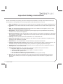
DPF710K
Table of Contents
Important Safety Instructions ---------------------------------------------------------------------------------------------------------- 3
Introduction
---------------------------------------------------------------------------------------------------------------------- 4
Product Features
---------------------------------------------------------------------------------------------------------------------- 5
What’s in the Box? ---------------------------------------------------------------------------------------------------------------------- 6
Installation
---------------------------------------------------------------------------------------------------------------------- 7
homebase Refrigerator Installation --------------------------------------------------------------------------------------------- 7
homebase Countertop Installation ---------------------------------------------------------------------------------------------- 8
homebase Wall Mount Installation Using the Wall Mount Bracket ---------------------------------------------------- 9
homebase Wall Mount Installation Using the Angle Mount Brackets ------------------------------------------------- 10
Internal Battery Activation and/or Replacement ---------------------------------------------------------------------------- 11
Controls, Indicators and Connectors ------------------------------------------------------------------------------------------------ 12
Accessory Placement -------------------------------------------------------------------------------------------------------------------- 13
Operating the Homebase --------------------------------------------------------------------------------------------------------------- 14
Preliminary Connections ---------------------------------------------------------------------------------------------------------- 14
Connecting the Power ------------------------------------------------------------------------------------------------------- 14
Inserting the Memory Card/USB Device ------------------------------------------------------------------------------- 14
Power On/Main Menu -------------------------------------------------------------------------------------------------------------------- 15
Preliminary Checks ----------------------------------------------------------------------------------------------------------------- 15
Power On/Main Menu -------------------------------------------------------------------------------------------------------------- 15
Memo Feature
---------------------------------------------------------------------------------------------------------------------Calendar Memos -------------------------------------------------------------------------------------------------------------------Recording Calendar Memos ----------------------------------------------------------------------------------------------Reviewing Calendar Memos -----------------------------------------------------------------------------------------------
16
17
17
18
Countdown Timer
---------------------------------------------------------------------------------------------------------------------- 19
Photo Menu
---------------------------------------------------------------------------------------------------------------------- 20
Photo Library Menu ---------------------------------------------------------------------------------------------------------------------- 21
External Media Menu --------------------------------------------------------------------------------------------------------------------- 22
Settings
1.
2.
3.
4.
2
General
General
General
General
---------------------------------------------------------------------------------------------------------------------Setup - Photo Mode Selection --------------------------------------------------------------------------------Setup - Time/Date Setting --------------------------------------------------------------------------------------Setup - Alarm Setting --------------------------------------------------------------------------------------------Setup - Clock Display --------------------------------------------------------------------------------------------
23
23
24
25
26
Technical Data
---------------------------------------------------------------------------------------------------------------------- 27
Warranty
---------------------------------------------------------------------------------------------------------------------- 28
DPF710K
Important Safety Instructions
Please read all safety and operating instructions carefully before installation, and keep these instructions handy for
future reference. Take special note of all warnings listed in these instructions and on the unit.
1. Water and Moisture: The unit should not be used near water. For example: near a bathtub, swimming pool, etc.
2. Ventilation: The unit should be situated so that its location or position does not interfere with its proper ventilation.
3. Heat: The unit should be situated away from heat sources such as radiators, heat registers, stoves, or other
appliances (including amplifiers) that produce heat.
4. Power Source: The unit should be connected to a power supply only of the type described in the operating
instructions or as marked on the appliance.
5. Power Cord Protection: Power cords should be routed so that they are not likely to be walked on or pinched by
items placed up or against them. It always best to have a clear area from where the cord exits the unit to where
it is plugged into an AC outlet.
6. Cleaning: The unit should be cleaned as needed with a soft, non-abrasive cloth.
7. Object and Liquid Entry: Care should be taken so that objects do not fall and liquids are not spilled into any
openings or vents located on the product.
8. Attachments: Do not use attachments not recommended by the product manufacturer.
9. Lightning and Power Surge Protection: Disconnect the unit from AC power during any electrical storm in the
immediate vacinity. This will prevent damage to the product due to lightning and power-line surges.
10. Overloading: Do not overload wall outlets, extension cords, or integral convenience receptacles as this can
resulting in a risk of fire or electric shock.
11. Damage Requiring Service: This unit should be serviced by qualified service personnel when:
a. The power supply cord or plug has been damaged.
b. Objects have fallen into or liquid has been spilled in the product enclosure.
c. The unit has been exposed to rain.
d. The unit has been dropped or the enclosure damaged.
e. The unit exhibits a marked change in performance or does not operate normally.
12. Servicing: The user should not attempt to service the unit beyond those methods described in the User's
Manual. Service methods not covered in the operating instructions should be referred to qualified service
personnel.
DPF710K
3
Introduction
Your homebase allows you to:
Display your digital photos from its internal memory, a memory card, or USB memory devices
Record and retrieve audio messages
Use the calendar to set audio and/or event reminders
Display time and date
Use a timer, set an alarm
Leave a written message on the front of the unit or the Post-it
4
®
pad.
DPF710K
Product Features
Overall Description :
•
•
•
•
•
•
•
7-inch color LCD displays photos, calendar and clock
•
Post-it
•
•
•
•
•
•
3-key navigation for simple operation
DPF710K
512 MB of memory-enough for more than 100 pictures depending on image size
Internal microphone for recording digital voice messages
Internal speakers with volume control
Magnetic border for posting notes, coupons, etc.
LED indicator lights when there's a message
Erasable white board and dry erase marker for quick notes and messages
®
notes for lists and reminders
Multiple mounting options: refrigerator, wall and countertop.
Supports SD/MMC, MS, xD, and CF memory cards and USB flash drives
Interactive Calendar and Digital Clock
Digital clock with alarm
Countdown timer
5
What’s in the Box?
homebase
Wall Mount Bracket (1)
AC to DC Power Adapter (1)
Angle Mount Bracket (2)
Post-It ® Note Pad (1)
Button Magnet (2)
Adhesive Foam Pad (2)
Wire Management System (3)
(Black, White, Clear)
Dry Erase Marker (1)
Plastic Wall Anchor (2)
Flat-Head Self-Tapping
Screw (2)
6
Double-Sided Tape (1)
Mounting Hole Template (1)
DPF710K
Installation
homebase Bracket Mounting Holes
Wire Post(s)
Power Adapter
Wire Notch
Refrigerator Door Front Surface
DC Input
Connector
Refrigerator
Door Seal
DC Power Wire
1 inch
Power Adapter
Wire Notches
Wire Cover
homebase
Adhesive
Foam Pads
Wire Cover
Wall Mount Bracket
See Step 9
Caution
Below
homebase Refrigerator Installation
1. Remove the protective backing from one side only of the two adhesive pads and position them on the back of the wall
mount bracket as shown.
2. Clean the homebase mounting area on the refrigerator with isopropyl alcohol; do not use a glass cleaner.
3. Place the wall mount bracket in the desired area and level the top of the bracket.
Note:
Before removing the remaining protective backing from the two adhesive pads, be sure of the homebase
mounting location as the adhesive pads are not designed to be removed and repositioned once they are
applied to the refrigerator surface.
4. Remove the protective backing from the two adhesive pads, line up the top of the bracket, and firmly press and hold the
bracket in place on the refrigerator surface to ensure the pads adhere securely.
Note:
3M™ recommends waiting 24 hours for maximum adhesion prior to mounting your homebase to the mounting
bracket.
5. Connect the power adapter plug to the DC input connector at the rear of the homebase.
6. Choose the direction of the adapter wire in reference to the AC wall outlet. Place the DC wire in the corresponding wire
notch.
7. Check the amount of wire required to reach the AC outlet. Spool excess wire on the four posts inside the rear cavity of
the homebase.
8. Attach the homebase to the bracket by lining up the homebase bracket mounting holes with the wall bracket mounting
tabs, and slide the homebase down until the mounting tabs engage the mounting hole slots.
9. Cover the power adapter wire with the clear, black or white wire cover; seal the cover using the double-sided tape and
dress the wire, adhering it to the refrigerator surface.
Caution: The power adapter wire routing follows the right angle contour of the refrigerator door. Do NOT cover the DC power
adapter wire using the double-sided tape after the 90 degree transition from the front refrigerator surface to the side
surface and for at least one inch rearward of the refrigerator seal. This will allow movement of the power adapter wire as
the refrigerator door opens and closes.
DPF710K
7
Installation (Cont)
Angle Bracket Mounting Holes
homebase
Unit
DC Input Connector
Wire Post(s)
Power Adapter
Wire Notches
Bracket Upper
Mounting Tabs
Bracket Lower
Mounting Tabs
Angle Mount
Brackets
homebase Countertop Installation
1. Find a suitable location on the countertop adjacent to an AC wall outlet.
2. Connect the power adapter plug to the DC input connector at the rear of the homebase.
3. Choose the direction of the adapter wire in reference to the AC wall outlet. Place the DC wire in the corresponding wire notch.
4. Check the amount of wire required to reach the AC outlet. Spool excess wire on the four posts inside the rear
cavity of the homebase.
5. Attach each angle mount bracket to the homebase by lining up the individual angle mount bracket upper
mounting tab with the associated homebase mounting hole.
6. Push each angle mount bracket towards the top of the homebase until the upper mounting tab engages the
mounting hole slot; when the bottom of the angle bracket contacts the homebase, the tab on the bottom of the
angle bracket snaps into place.
7. Place the homebase in the desired location.
8
DPF710K
Installation (Cont)
Flat-Head Self-Tapping
Screw (2)
Wall Surface
Drill 1/4" Hole
(2 Places)
Mounting Hole
Template
Wall Bracket
Mounting Tabs
Wall Mount
Bracket
Plastic Wall
Anchor (2) if
Needed
homebase Wall Mount Installation Using the Wall Mount Bracket
Note: If the wall bracket is to be mounted using the foam adhesive pads, the procedure will be the same as that
for the refrigerator mount as described on page 7.
If the wall bracket is to be mounted using screws, proceed as follows:
1. Position the mounting hole template at the desired place on the wall; level the template and mark the
position of the two upper holes.
2. Drill two holes using a 1/4" (6mm) drill bit. If a wall stud is not present, insert the plastic anchors into the holes
until flush with the wall surface .
Caution: Do not over tighten the screws; otherwise, the wall bracket could be damaged
3. Align the wall bracket with the two holes and/or wall anchors; insert two flat-head screws and secure the wall
bracket to the wall.
4. Connect the power adapter plug to the DC input connector at the rear of the homebase.
5. Choose the direction of the adapter wire in reference to the AC wall outlet. Place the DC wire in the corresponding wire notch.
6. Check the amount of wire required to reach the AC outlet. Spool excess wire on the four posts inside the rear
cavity of the homebase.
7. Attach the homebase to the bracket by lining up the homebase bracket mounting holes with the wall bracket
mounting tabs, and slide the homebase down until the mounting tabs engage the mounting hole slots.
8. Cover the power adapter wire with the clear, black or white wire cover; seal the cover using the double-sided
tape and dress the wire, adhering it to the wall surface.
DPF710K
9
Installation (Cont)
Plastic Wall Anchor (2)
if Needed
Drill 1/4” Hole
(2 Places)
Angle Mount Bracket
Mounting Tabs
Wall Surface
Flat-Head Self-Tapping
Screw (2)
Angle Mount
Bracket (2)
Mounting Hole
Template
homebase Wall Mount Installation Using the Angle Mount Brackets
Note: Foam adhesive pads are not recommended when mounting the angle mount brackets to a wall surface.
Mount the brackets to the wall surface as follows:
1. Position the mounting hole template at the desired place on the wall; level the template and mark the
position of the two lower holes.
2. Drill two holes using a 1/4” (6mm) drill bit. If a wall stud is not present, insert the plastic anchors into the holes
until flush with the wall surface .
Caution: Do not over tighten the screws; otherwise, the angle mount bracket could be damaged.
3. Align each angle mount bracket with the respective hole and/or wall anchors; insert a flathead screw through
each bracket and secure the bracket to the wall.
4. Connect the power adapter plug to the DC input connector at the rear of the homebase.
5. Choose the direction of the adapter wire in reference to the AC wall outlet. Place the DC wire in the corresponding wire notch.
6. Check the amount of wire required to reach the AC outlet. Spool excess wire on the four posts inside the rear
cavity of the homebase.
7. Attach the homebase to each bracket by lining up the homebase bracket mounting hole with the associated
bracket mounting tabs, and slide the homebase down until each mounting tab engages the mounting hole slot.
8. Cover the power adapter wire with the clear, black or white wire cover; seal the cover using the double-sided
tape and dress the wire, adhering it to the wall surface.
10
DPF710K
Installation (Cont)
Internal Battery Activation and/or Replacement
A type CR2032 battery is installed in a compartment behind the front
panel of the homebase. If the unit is being used for the first time, the
battery must be activated. A plastic insulator prevents contact with the
battery terminals. This insulator must be removed for the calendar/
clock backup functions to operate. To remove the insulator, simply pull
out the plastic tab extending from the right side of the unit below the
marker pen.
To remove and replace the battery, proceed as follows:
1.
2.
3.
4.
5.
6.
7.
8.
Post-It ® note pad
storage
Marker pen
storage
Pull out this tab
(“REMOVE THIS
TAB”) completely
to enable battery
operation
Lay the homebase on a flat surface with the front panel facing up.
Grasp the center of the front panel at the top and bottom edge and bow the panel out until it clears the left side
by the control buttons. Remove the panel to reveal the battery compartment cover.
With your thumb, press the cover in the direction indicated by the arrow until it disengages. Lift off the cover.
Carefully remove the battery.
Insert the battery in the compartment paying special attention to battery orientation (+ side facing up).
Replace the battery compartment cover by first engaging the right-hand tabs in the slots. Then press down and
slide the cover to the left to secure the cover in place.
Replace the front panel by engaging the right side under the protruding lip; then slightly bow the panel out and
slide the left side under the lip by the control buttons.
The battery backup feature should now be operational.
Control Buttons
Protruding Lip
(Left Side)
Protruding Lip
(Right Side)
Battery Compartment
homebase Front Panel
DPF710K
Battery Compartment
Cover
Button-Type Battery
(CR2032)
11
Controls, Indicators and Connectors
1
5
2
6
3
7
4
8
9
13
10
14
11
12
15
1. Power On/Off Switch
2. USB Connector
3. SD/MMC/MS/XD Connector
4. CF Connector
5. Up ( ) Navigation Button
6. OK / MENU Button
7. Down ( ) Navigation Button
8. MEMO Button
9. LCD Display
10. LED Indicator
11. Memo Writing Surface
12. Microphone
13. Speakers
14. - Volume + Control
15. DC Input Connector
12
DPF710K
Accessory Placement
Note Pad Storage
Receptacle
Post-It® Note Pad
Dry Erase Marker
homebase
DPF710K
Marker Storage
Receptacle
13
Operating the homebase
Preliminary Connections
Prior to initial operation, connection must be made to the power source and the tab (“REMOVE THIS TAB”) on the right
side of the unit must be removed to enable backup battery operation.
Connecting the Power. Power to the homebase is provided by the AC-to-DC wall adapter which delivers +9VDC to
the DC input connector at the rear of the unit. Refer to the installation procedures outlined previously for the methods
involved in connecting the wall adapter plug to the power input connector, and the routing and dressing of the adapter
power cable. The figure below illustrates a typical installation.
DC Input
Connector
Cable Notch
homebase
(Rear View)
Wall Outlet
AC-to-DC Wall
Adapter
Inserting the Memory Card/USB Device. All of the memory devices attach at the left side of the homebase and can
consist of a USB Flash Memory, Compact Flash (CF) Memory Card, Multi-Media Card (MMC), Memory Stick (MS)
Card, Secure Digital (SD) Card , or and xD Card. All of these devices are inserted in their respective receptacles with
the label side facing to the rear.
USB Flash
Memory
Secure Digital (SD),
Memory Stick (MS),
Multi-Media Card (MMC)
xD Card
homebase
(Rear View)
Label Side
(Typical)
14
Compact Flash
Memory (CF)
DPF710K
Power On/Main Menu
Preliminary Checks
With the homebase properly installed, perform the following precautionary checks prior to power application:
1.
2.
3.
Make sure the power switch on the upper left side of the unit is in the Off (down) position.
Check the wall adapter and power cable for cuts, nicks, kinks, etc.
Plug the adapter plug into a wall outlet.
Power On/Main Menu
1.
2.
3.
Place the power switch in the On (up) position. In a few seconds, the homebase logo appears on the LCD
screen, followed about 5 seconds later by the slide show if an input memory device is connected; otherwise,
the homebase demonstration (demo) slide show will start.
Note: The demo slide show images can be erased.
If the slide show is displayed, and the OK / MENU button is pressed, the main menu is displayed with
calendar highlighted. If no input device is connected when power is applied, the Homebase logo remains on
the screen until the OK / MENU button is pressed; the main menu appears once again.
If an input device containing pictures is connected while the main menu is displayed, the slide show thumbnail
pictures are displayed.
Turn unit on
No internal
Input device
images
connected
Slide show begins
audiovox
audiovox
Demo slide show
begins (default)
Press OK
Main menu appears
with calendar highlighted
exit
memo
memo
calendar
timer
photo
setting
DPF710K
15
Memo Feature
Highlight MEMO in the main menu using the up/down
buttons ( / )
exit
-----and press OK -----
memo
calendar
timer
photo
highlight record using the
down button ( ) and press OK
-------Record is active------
settings
exit
record
play / erase
Or press the
memo button
When record is finished --Press the down button ( ) to
highlight desired function, e.g.,
review, keep / exit, record
again, cancel
erase all
recording...
ok button stop
record
review
keep / exit
record again
Highlight keep / exit
and press OK to save in
memory; the memo
for: LED now lights
cancel
Highlight play / erase and
press OK; the memo list
appears on the screen
review
keep / exit
record again
cancel
exit
play
memo 1 (00/00/00) erase
review
memo 2 (00/00/00) keep
keep / exit
memo33(00/00/00)
(00/00/00) keep as new
memo
memo 4 (00/00/00)
1/2
Highlight the desired memo
and press OK; the play/erase/
keep/keep as new options appear
on the screen. Note: Unplayed
memos are displayed in green
16
saving memo -----
record again
cancel
memo 5 (00/00/00)
Back to homebase
screen or slide show
DPF710K
Calendar Memos
1. Recording Calendar Memos
Highlight calendar in the main menu using the up/down buttons ( / )
-----and press OK-----
exit
memo
memo
calendar
Note: Use the up/down buttons ( / )
to scroll from day to day and pressing
and holding up/down buttons ( / ) for
2 seconds advances to the next month.
timer
photo
setting
December 2008
Sun
1
Mon
2
Tue
3
Wed
4
Thu
5
Fri
6
7
8
9
10
11
12
13
14
15
16
17
18
19
20
21
22
23
24
25
26
27
28
29
30
31
Sat
Press MEMO button and use
the up/down buttons ( / ) to
highlight voice or event memo
Note: Calendar voice memos
automatically erase after 72
hours from the date the memo
is set to play.
exit
back
event memo
Highlight event memo and
press OK
back
birthday
Highlight voice memo
and press OK
voice memo
recording...
ok button stop
record
review
anniversary
keep / exit
holiday
record again
special
Press OK and use the up/down buttons
( / ) to highlight the event type. Press OK
to set it on or as a yearly reminder; the event
is flagged on the calendar screen by the
appropriate icon.
DPF710K
Press OK to begin recording a
voice message (refer to the memo
feature described previously
17
Calendar Memos (Cont)
2. Reviewing Calendar Memos
Highlight calendar in the main menu using the up/down buttons ( / )
Note: Use the up/down buttons ( / )
to scroll from day to day and pressing
and holding up/down buttons ( / ) for
2 seconds advances to the next month.
-----and press OK-----
exit
memo
memo
calendar
timer
photo
setting
December 2008
Sun
1
Mon
2
Tue
3
Wed
4
Thu
5
Fri
6
7
8
9
10
11
12
13
14
15
16
17
18
19
20
21
22
23
24
25
26
27
28
29
30
31
Highlight event
memo and press OK
Sat
Press the OK button and use the
up/down buttons ( / ) to highlight
voice or event memo
Highlight voice memo and
press OK
exit
back
voice memo
event memo
When the calendar is displayed,
press and hold the up or down button
( / ) more than 2 seconds to select
the month; a momentary press of
either button highlights the date
exit
play
memo 1
erase
memo 2
keep
erase all
Note: Pressing erase all will
erase all calendar voice memos.
exit
memo 1
memo 2
memo 3
memo 4
Special Event Icon
Anniversary Reminder Icon
Birthday Reminder Icon
Holiday Reminder Icon
18
DPF710K
Countdown Timer
Highlight timer in the main menu using the up/down buttons ( / )
exit
----and press OK----
memo
calendar
timer
photo
setting
countdown timer
00:10:00
h
m
s
A split screen display appears with
the countdown timer on the left and
a slide picture on the right. If the
slide show is in progress when the
timer function is selected, the slide
show stops at the current picture
and appears in the timer display
background.
a.
When the timer display appears, the hours (h) digits are flashing and 10 minutes is indicated.
b.
Use the up/down buttons ( / ) to set the hours and press OK.
c.
The minutes digits are now flashing; use the up/down buttons ( / ) to set the minutes (m) and press OK.
d.
The minutes digit decreases by 1 and the seconds (s) digits begin to count down from 59, initiating the countdown sequence.
e.
To terminate the countdown prior to timeout, press the OK button.
f.
If the countdown is allowed to time out, time’s up! appears above the digits, the display automatically returns
to the slide show and the alarm sounds for 2 minutes, or until the OK button is pressed.
DPF710K
19
Photo Menu
Highlight photo in the main menu using the up/down buttons ( / )
exit
----and press OK----
memo
memo
calendar
timer
Highlight external media
using the up/down buttons
( / ) and press OK
photo
settings
exit
external media
photo library
slide show
Highlight photo library
using the up/down buttons
( / ) and press OK to
access photos stored in
the library file. If none
exists, this feature is not
supported. (See Photo
Library Menu)
Select the slide
show feature
desired and
press OK
Determine the
order in which the
slide show pictures
are to be shown
and press OK
20
exit
exit
external media
USB
photo library
sd/mmc/xd/ms
slide show
CF
Highlight slide show
using the up/down
buttons ( / ) and
press OK
exit
slide show order
slide show time
exit
slide show order
slide show time
Highlight USB, sd/mmc/
xd/ms, or CF using the
up/down buttons ( / )
and press OK
exit
exit
external media
USB
photo library
sd/mmc/xd/ms
slide show
CF
The display will show thumbnail images on a
connected external media card, prioritizing SD/
MMC/xD/MS over USB and CF. (See External
Media Menu)
Determine how long
each slide show picture
remains displayed on
screen and press OK
exit
5 secs
slide show order
10 secs
slide show time
30 secs
DPF710K
Photo Library Menu
Full screen picture
appears with slide show
menu overlay with back
highlighted
Slide show thumbnail
display appears when
input device connected
Use the up/down buttons ( / )
to highlight and select desired
picture
Press OK
1 / 62
exit
back
single slide display
delete
next
rotate
Select back and press OK to return to
thumbnail screen; select exit and press
OK to display full screen slide show
1.
Single Slide Display -
2.
Delete - Removes selected image from internal memory by selecting yes. Selecting all removes all images
from internal memory.
3.
Next - Advances to the next slide in order after pressing the OK button.
4.
Rotate - Rotates the selected image in 90 degree increments.
DPF710K
Stops slide show and displays only selected picture. To resume the slide show, turn
the Single Slide Display function to off.
21
External Media Menu
Full screen picture
appears with slide show
menu overlay with back
highlighted
Slide show thumbnail
display appears when
input device connected
Use the up/down buttons ( / )
to highlight and select desired
picture
exit
back
copy
next
Press OK
copy all
Select back and press OK to return to
thumbnail screen; select exit and press
OK to display full screen slide show
Use the up/down buttons ( / ) to
highlight the next option
Use the up/down buttons ( / ) to
highlight the copy option
Press OK
exit
exit
back
back
copy
copy
next
next
copy all
copy all
Press OK
Use the up/down buttons
( / ) to highlight the copy
all option
Slide show advances to the
next picture which can be
copied if desired
exit
back
copy
next
copy all
22
yes/no options appear. If yes is selected,
the current slide picture is copied into
internal memory
Press OK
yes/no options appear. If yes
is selected, all slide pictures
are copied into internal
memory
DPF710K
Settings
1. General Setup - Photo Mode Selection
Highlight settings in the main menu using the up/down buttons ( / )
exit
memo
memo
calendar
timer
photo
settings
and press OK
Highlight general setup using the up/down buttons ( / )
exit
general setup
time / date setup
alarm
clock display
and press OK
1.
Photo Mode - Select between normal mode and wide screen.
2.
Activation Time - Set a time for the unit’s display to turn off and turn on to conserve energy. Pressing any
key while in the energy conservation mode will re-activate the display.
3.
Clear Memory - Will delete all images and memos in memory.
4.
Default - Restore all factory settings.
DPF710K
23
Settings (Cont)
2. General Setup - Time / Date Setting
a.
In the Settings menu, highlight time / date setup using the up/down buttons ( / ) and press OK.
b.
The time / date display appears with the hour digit(s) flashing.
c.
Use the up/down buttons ( / ) to set the hour and press OK.
d.
The minutes digits are now flashing; use the up/down buttons ( / ) to set the minutes and press OK.
e.
The AM/PM indication now flashes; use the up/down buttons ( / ) to set the AM or PM indication and press
OK.
f.
On the top date line above the time, the month indication now flashes; use the up/down buttons ( / ) to set
the month and press OK.
g.
Flashing now advances to the day of the month indication; use the up/down buttons ( / ) to set the day and
press OK.
Note:
When the day of the month and year are set correctly, the week day adjusts automatically to indicate
the correct day of the week.
h.
Flashing now advances to the year indication; use the up/down buttons ( / ) to set the year and
press OK.
i.
Time/date setup is complete and the display reverts to the Settings menu with time/date setup highlighted.
Wednesday - Dec. 17th, 2008
am
10:00
24
DPF710K
Settings (Cont)
3. General Setup - Alarm Setting
In the Settings menu, highlight alarm using the up/down buttons ( / ) and press OK
To program the alarm time,
use the up/down buttons ( / )
to highlight alarm set and press
OK
exit
alarm on/off
alarm set
Clock is displayed in the center of the
screen (below), along the bottom edge
of the screen, or in the split screen
configuration
exit
alarm on/off
alarm set
Highlight alarm on/
off using the up/down
buttons ( / ) and
press OK
Wednesday - Dec. 17th, 2008
am
10:00
a.
The time / date display appears
with the hour digit(s) flashing.
exit
alarm on/off
b.
Use the up/down buttons ( / ) to set the hour
and press OK.
c.
The minutes digits are now flashing; use the
up/down buttons ( / ) to set the minutes and
press OK.
d.
The AM/PM indication now flashes; use the
up/down buttons ( / ) to set the AM or PM
indication and press OK.
e.
Complete alarm set by pressing OK.
Note:
DPF710K
If the alarm is set, the clock icon (
tations described.
Highlight the desired
option and press OK
alarm set
exit
On
alarm on/off
Off
alarm set
) is also displayed on the screen in each of the clock presen-
25
Settings (Cont)
4. General Setup - Clock Display
In the settings menu, to display the clock on the screen, highlight clock display using the up/down buttons ( / )
exit
and press OK
memo
general setup
exit
off
memo setup
general
screen bottom edge
time / date setup
time / date setup
large centered
alarm
alarm
split screen
clock display
clock display
Select the clock presentation desired
using the up/down buttons ( / ) and press OK
The clock can be positioned at the bottom edge of the screen, in large letters in the center of the screen, in the split
screen configuration, or be turned off completely (off).
Wednesday - Dec.. 17th, 2008
11:23 am
Clock icon displayed
on bottom of screen
Wednesday - Dec. 17th, 2008
am
10:00
Clock icon displayed at left in split
screen configuration
Clock icon displayed
in center of screen
26
DPF710K
Technical Data
Specifications
•
•
•
•
•
•
•
•
•
•
•
•
•
•
•
Digital Picture Frame
7” LCD
Aspect Ratio
16:9
Resolution:
480 x 234 pixels
Internal Flash Memory
512 MByte
USB Connector
Provides interface for external USB memory device
SD/MMC/MS/xD Card Slot
Provides interface for memory device
CF Connector
Provides interface for CF memory device
Date/Time
Digital Calendar and Clock Feature
Voice Messages
Internal microphone for digital audio recording
Audio Output
Internal speakers (2) with separate volume control
Menu Navigation
3 keys
Message Indicator
Green LED
Reminder Function
The memo for: LED will light when there is an unheard voice
memo or an activated calendar voice memo
Memory Backup for the Clock
Internal backup battery data Info …..etc. Battery type CR2032
Image File Type Handling
JPEG
DPF710K
27
Warranty
90 DAY LIMITED WARRANTY
Applies to Audiovox Video Products
AUDIOVOX ELECTRONICS CORP. (the Company) warrants to the original retail purchaser of this product that should
this product or any part thereof, under normal use and conditions, be proven defective in material or workmanship within
ninety (90) days from the date of original purchase, such defect(s) will be repaired or replaced with reconditioned
product (at the Company's option) without charge for parts and repair labor. A game controller, if supplied, is similarly
warranted for ninety (90) days.
To obtain repair or replacement within the terms of this Warranty, the product is to be delivered with proof of warranty
coverage (e.g. dated bill of sale), specification of defect(s), transportation prepaid, to the Company at the address
shown below.
This Warranty does not extend to the elimination of externally generated static or noise, to correction of antenna
problems, to costs incurred for installation, removal or reinstallation of the product, or to damage to digital memory/
media devices, gaming devices, discs, speakers, accessories, or electrical systems.
This Warranty does not apply to any product or part thereof which, in the opinion of the Company, has
suffered or been damaged through alteration, improper installation, mishandling, misuse, neglect,
accident, or by removal or defacement of the factory serial number/bar code label(s). THE EXTENT OF
THE COMPANY'S LIABILITY UNDER THIS WARRANTY IS LIMITED TO THE REPAIR OR REPLACEMENT PROVIDED ABOVE AND, IN NO EVENT, SHALL THE COMPANY'S LIABILITY EXCEED THE
PURCHASE PRICE PAID BY PURCHASER FOR THE PRODUCT.
This Warranty is in lieu of all other express warranties or liabilities. ANY IMPLIED WARRANTIES,
INCLUDING ANY IMPLIED WARRANTY OF MERCHANTABILITY, SHALL BE LIMITED TO THE
DURATION OF THIS WRITTEN WARRANTY. ANY ACTION FOR BREACH OF ANY WARRANTY
HEREUNDER INCLUDING ANY IMPLIED WARRANTY OF MERCHANTABILITY MUST BE BROUGHT
WITHIN A PERIOD OF 12 MONTHS FROM DATE OF ORIGINAL PURCHASE. IN NO CASE SHALL THE
COMPANY BE LIABLE FOR ANY CONSEQUENTIAL OR INCIDENTAL DAMAGES FOR BREACH OF
THIS OR ANY OTHER WARRANTY. No person or representative is authorized to assume for the
Company any liability other than expressed herein in connection with the sale of this product.
Some states do not allow limitations on how long an implied warranty lasts or the exclusion or limitation of incidental
or consequential damage so the above limitations or exclusions may not apply to you. This Warranty gives you specific
legal rights and you may also have other rights which vary from state to state.
Audiovox Electronics Corporation, 150 Marcus Blvd., Hauppauge, New York 11788
• 1-800-645-4994
128-5556G
28
28
DPF710K
Notes
DPF710K
29
Notes
30
DPF710K
Notes
DPF710K
31
Audiovox Electronics Corp.
150 Marcus Boulevard
Hauppauge, NY 11788
DPF710K
128-8269B