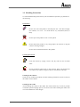
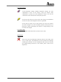
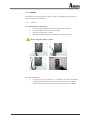
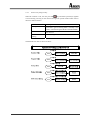
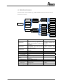
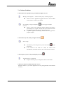
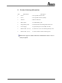
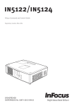
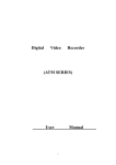
1
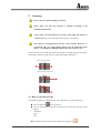
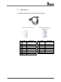
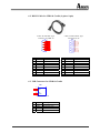
User’s Manual PT-10/PT-12 Portable Data Collectors DOC NO. UM-PT105-01 Oct. 2006 Version 2.0 CAUTION: This user’s manual may be revised or withdrawn any time without prior notice. Copyright 2005, Argox Information Co., Ltd. All rights reserved. This manual may not, in whole or in part, be copied, photocopied, reproduced, translated or converted to any electronic or machine readable form without prior written consent of Argox. Limited warranty and disclaimers By opening the package of this product you agree to become bound by the liability and warranty conditions as described below. Under all circumstances this manual should be read attentively before installing and or using the product. In no event, Argox will be liable for any direct, indirect, consequential or incidental damages arising out of use or inability to use both the hardware and software, even if Argox has been informed about the possibility of such damages. A series number appears on all Argox products. This official registration number is strictly related to the device purchased. Make sure that the serial number appearing on your Argox device has not been removed. Servicing by our service department can only be carried out under warranty. All Argox products are warranted for the legal warranty period after purchase, covering defects in material and workmanship. Argox will repair or, at its opinion, replace products that prove to be defective in material or workmanship under proper use during the warranty period. Argox will not be liable in case modifications are made by the customer. In such case the standard repair charge will be applicable. The standard charge for repair will also be applicable in case no defect is found at all. These rules also apply for products that are still under warranty. Therefore, you are advised to have the product specifications always at hand. Trademarks used are property of their respective owners. The general use and functioning of the collector together with the cradle will be described in this manual. The exact behavior of the collector depends on the user application that is running. For instructions about applications please consult the documentation of that software. Please read this manual carefully before using the collector, to maximize the efficiency of this collector. II Table of Content 1. INTRODUCTION................................................................................................. 1 2. SPECIFICATIONS............................................................................................... 2 3. GETTING STARTED .......................................................................................... 4 3.1 DETAILED VIEW ............................................................................................ 4 3.1.1 Collector ............................................................................................. 4 3.1.2 Cradle ................................................................................................. 6 3.2 HANDLING PRECAUTIONS ............................................................................. 8 3.3 ASSEMBLY .................................................................................................... 10 3.3.1 Collector ........................................................................................... 10 3.3.2 Cradle ............................................................................................... 11 3.4 INSTALLING, REPLACING AND CHARGING BATTERIES .............................. 12 3.5 INSTALLING IN A SYSTEM ............................................................................ 16 3.5.1 Via RS-232 Cable.............................................................................. 16 3.5.2 Via CRD-10 Cradle........................................................................... 17 4. OPERATION OF THE COLLECTOR ............................................................ 18 4.1 SOFTWARE DESCRIPTION ............................................................................ 18 4.2 HARDWARE DESCRIPTION........................................................................... 19 4.2.1 Display Description .......................................................................... 19 4.2.2 Keypad Description........................................................................... 20 4.2.3 Function Key Description ................................................................. 20 4.2.4 System Menu Language Change ....................................................... 21 4.2.5 Power Management .......................................................................... 21 4.2.6 Splashed Logo Description ............................................................... 22 4.3 POWER –ON OPERATION ............................................................................. 22 4.3.1 Power on mode ................................................................................. 22 4.3.2 Power on by using hot key ................................................................ 23 4.4 MAIN MENU STRUCTURE ............................................................................ 24 4.4.1 Applications ...................................................................................... 25 4.4.2 Remote Link ...................................................................................... 26 4.4.3 System Tools...................................................................................... 27 4.4.3.1 Scan Test ......................................................................................... 27 4.4.3.2 Edit Data ......................................................................................... 27 4.4.3.3 File Manager ................................................................................... 27 4.4.3.4 Com Port Test ................................................................................. 27 4.4.4 Setting ............................................................................................... 28 4.4.4.1 BIOS Setting ................................................................................... 28 4.4.4.2 Boot Configure................................................................................ 30 4.4.4.3 Password ......................................................................................... 30 4.4.4.4 F/W Upgrade................................................................................... 30 III 5. SCANNING ......................................................................................................... 31 5.1 HOW TO READ THE BARCODE ...................................................................... 31 5.2 BARCODE READING PROBLEMS ................................................................... 32 6. CABLE PIN-OUT ............................................................................................... 33 6.1 RS232 CABLE FOR PT-10 / PT-12 (9-PIN TO 10-PIN).................................. 33 6.2 RS232 CABLE FOR CRD-10 CRADLE (9-PIN TO 9-PIN) .............................. 34 6.3 USB CONNECTOR FOR CRD-10 CRADLE ................................................... 34 7. TROUBLE SHOOTING .................................................................................... 35 7.1 7.2 7.3 7.4 8. GENERAL CHECKS ....................................................................................... 35 COMMUNICATION PROBLEMS ..................................................................... 35 READ OPERATION PROBLEMS .................................................................... 36 COLLECTOR PROBLEMS .............................................................................. 37 PRODUCT ORDERING INFORMATION ..................................................... 38 IV 1. Introduction The PT series portable data collector (PDC) is well suited for a variety of portable applications. It has a built-in CCD scanning engine that can scan all popular bar code labels at varying distance (up to 13 inches). User’s applications can be downloaded to the collector to adapt the collector to the user’s situation. The operation power is supplied by the main battery (AA-size Alkaline batteries for PT-10, and a rechargeable Ni-MH battery pack for PT-12). The CRD-10 cradle (only available for PT-12 model) is a communication and charging station for data transmission between the (host) computer system and the collector. It communicates with the collector through RS-232 serial or USB interface. The CRD-10 cradle will charge the rechargeable battery pack in the collector through the electrical contacts. And it also provides an extra charging slot for a spare battery pack if necessary. 1 2. Specifications Feature PT-10 PT-12 CPU/Memory Proprietary OS CPU RAM 32-bit RISC Processor with ARM core 1M SRAM 2M SRAM 1M flash ROM ROM Display 128 x 64 dots LCD Resolution LED backlight Backlight Scanner Scanner system Long Range CCD scanner 2048 pixels 0.127mm (5 mil) at PCS 90% Resolution Depth of field 330mm (code 39, 20 mils, 90% pcs) ≥30% PCS Scanning rate Readable barcode 100 scans/sec Code 39, UPC A/E, Cod 128, Int. 2 of 5, Codabar,Code 93, China Post Code, EAN-8/13, full ASCII code 39, ISBN/ISSN Keypad Number of keys 22 rubber keys Black Keypad color Cable Interface / Communication Data Rate PC interface 4800 bps ~ 115200 bps RS-232 RS-232 / USB Environment Operating temperature Storage temperature Shock resistance EMC 0~40℃ -20~70℃ 1.2M FCC Class-B, CE,UL 2 Power supply Main power Back up power 2 x AA Alkaline battery rechargeable Ni-MH battery pack 3V rechargeable Lithium battery Packing 9-Pins to 10-Pins 9-pins to 9-pins 2 x AA Alkaline battery Ni-HM battery pack Clip holder Yes Yes Hand strap Yes Yes Cradle No Yes Adapter No Yes Package Single PT-10 package Complete package w/cradle RS-232 Cable Battery Developing tools Software Windows based application generator:ArgoBuilder Software Development Kit (SDK) Program Language BSD C ANSI/ ISO Standard C 3 3. Getting Started 3.1 Detailed View 3.1.1 Collector Dimensions of Collector 140mm (L) x 67mm (W) x 25.7mm (H) Details of Collector LED Clip LCD Battery slot RS-232 port Battery unlock 1. Reading Window Optical beam of LED for barcode reading will be emitted from here 2. LED Indicator Can be used to indicate results, for example bar code reading / status of communication 4 3. LCD Display For displaying information and battery status Battery Battery 2/3 1/3 Battery Low Indicator Full Battery Life Battery Life Replace Immediately 4. Scan Key Read Key, switches LED beam on for barcode reading 5. Cursor Key Used for cursor LEFT, RIGHT, UP, and DOWN 6. ENT Key For confirming input 7. Character Keys For input of alpha-numeric and punctuation characters 8. Control Keys For controlling basic functions. Typical use as below: C : Cancel – As function of back space ESC : Escape – Escape from the current operation FN : Function – Function Key Alpha : Alpha – Toggle between alpha and numeric mode 9. Power Key For switching power On/Off 10. Multiple Function Socket For data transmission (PT-10 / PT-12) and battery charging (PT-12) 11. Clip Convenience for carrying with belt without handholding 12. Battery Unlock To release the lock for withdrawing the battery pack 13. Battery Slot The track of battery pack insertion and retrieval 14. Hand Strap For security of collector when a sudden drop happened 5 3.1.2 Cradle Dimensions of CRD-10 Cradle 130mm (L) x 100mm (W) x 67.6mm (H) Details of CRD-10 Cradle Front Power (communication) Charging Terminal slot Back Serial and charging port Charging port USB port Power port RS-232 port 1. Collector Slot Put the collector on the cradle through this slot for data transmission or charging 2. Power / Communication LED Indicator Green : Power on (collector not on cradle) Orange : Data transmission (communication) Collector insert into the cradle / Collector withdraw from the cradle 3. Charging LED Indicator Red flashing : Charging Green : Charging completed Red : Contact well 6 4. Serial and Charging Connector To connect with the multiple function socket on the collector for data transmission and charging 5. Charging Slot For charging a spare rechargeable battery pack 6. RS-232 C Socket For connecting to PC serial port through Argox RS232 cable 7. USB Socket For connecting to PC USB port through a standard USB cable 8. DC Input Socket Input for AC adapter 7 3.2 Handling Precautions To avoid malfunctioning and to ensure years of trouble free operation, pay attention to the following: General Use Do not use or leave the product in extremely hot area – like direct sunlight, near a heater, or in a car – or in areas that are very cold, humid, moist, or dusty. Do not expose the product to rain or water splash. Do not subject the product to very strong impact, do not throw or drop the collector from large heights. Do not allow a mechanical shock to the product. Cleaning Instruction Clean the exterior by wiping it with a soft, dry cloth. Do not use much water. Do not use thinner, white spirit or other solvents. These can discolour the case and the keys and has a negative effect on the lifetime of the keys. Cleaning of the collector Clean the scan window periodically for better reading performance, but do not hurt on the window with scratches. Cleaning of the cradle Avoid touching the contacts in the cradle. The contacts must stay as clean as possible to maintain optimal charging capacity. Do not use water when cleaning the cradle. This can cause malfunction in the chargers. 8 Use of the collector Avoid temperature changes. Sudden temperature changes can cause condensation to form on the collector. Using the collector while condensation is present can cause malfunction. Always wait until the condensation clears naturally before attempting operation. Do not leave the collector in an area where static charge is accumulated or near devices where electromagnetic emission is generated. Do not place any object on top of the collector. Do not lay the collector face down. Doing so can cause accidental operation of the power key or [ENT] key, which can discharge your batteries or change settings you do not want to be changed. Use of the cradle Do not place any product other than the PT-12 collector in the cradle. Maintenance There are no user-serviceable parts inside the collector or the cradle. So do not try to take it apart. The manufacturer will not be liable for any damage caused by the customers. In case of malfunction that can not be solved by the trouble-shooting instruction in this manual, please consult service department. 9 3.3 Assembly Follow the next steps to make your collector ready for installation in a system that is described further in the manual. 3.3.1 Collector To avoid drop use the hand strap. 1. Fix the small cord of the strap around the pillar of the collector. 2. Insert the handle of the strap in the thin loop. 3. The strap is fixed to the collector. 4. Hold the hand strap around the wrist when carrying the collector. Do not swing the collector around 1 2 3 4 Start with a full battery 1. To be sure of proper operation, it is advised to start with a full battery, charge the battery pack according to the instructions in the next chapter. 2. Click the battery pack into the collector as instructed in the next chapter. 10 3.3.2 Cradle Power Connection 1. 2. 3. Attach the DC jack of the AC adapter into the socket of the cradle. Then connect the AC adapter to the mains outlet. The LED on the cradle turns green. When the PT-12 collector with the rechargeable battery pack is placed in the cradle, the LED on the cradle turns orange first and turns green at once then it starts to charge the collector. When the PT-12 collector was removed from the cradle, the LED on the cradle turns orange first and turns green at once. Collector on cradle Take notice that the PT-12 cradle is designed for the PT-12 collector. No other type of collector can be placed into this cradle. This can cause damages to the connector on the cradle. 11 3.4 Installing, Replacing and Charging Batteries Wrong use of batteries might cause serious damage to the collector or to the cradle. In order to avoid damage, it is very important to take notice of the instructions. Insert full batteries (or a full-charged battery pack) before use of the collector. Never remove the main batteries (or battery pack) while the collector is turned on. Doing so can cause data in the collector to be deleted. When you do not use the collector for a long time, make sure the main batteries (or battery pack) have enough capacity. When there is not enough capacity in the main batteries (or battery pack), the backup battery can not be charged and will become too low. Only use recommended batteries. When other batteries are used, defects or other problems can occur. Before installing (new) batteries please make sure you are using the recommended batteries. Do not make a mistake regarding the polarity (+, -) of the battery. The collector will NOT work when the polarity is incorrect. Use the right charger for batteries. The rechargeable Ni-MH battery pack of Argox can be charged in the cradle when either it is in the collector or alone to the charging slot in the back of the cradle. Other rechargeable batteries need to be recharged in a separated battery-charging device. Follow the instructions for installing, charging, and removing the batteries very strictly. The products are not warranted for damage, defects, malfunction, or loss of data, resulting from incorrect use of batteries. Required batteries: The collector needs both main battery and backup battery for operation. 12 Main Battery The main battery can consist of: 1. Argox rechargeable battery pack (Ni-MH) (Ref. 1) To be recharged when placing the collector in the cradle or just put the battery pack in the charging slot of the cradle (alone). This battery is supplied with the PT-12 collector and is recommended by Argox. Ref. 1 2. Rechargeable batteries (Ref. 2) Batteries that are not supplied by Argox must be AA-size and absolutely leak-proof. Their positive and negative poles should entirely contact the springs. They need to be put in the empty pack (Ref. 3 & 4) that is supplied by Argox. They need to be recharged by a separate battery-charging device. The battery brand in the picture 2 & 4 is just for reference only. Ref. 2 Ref.3 3. Ref.4 Alkaline batteries (Ref. 5) Disposable AA-size alkaline batteries also can be used in PT-10 or PT-12. They need to be put in the empty pack that is supplied by Argox. Alkaline batteries can not be recharged. Ref.5 Backup Battery Use only one type of battery for backup: Back cell: ML-614S (Lithium, button type). It was soldered on the PCB and can NOT be changed or replaced by users. 13 How to charge Argox rechargeable battery pack in the cradle 1. Make sure that the Argox rechargeable battery pack is inserted in the collector. If the collector with the battery pack is placed in the cradle, the LED on the cradle will turn Orange first and turn to Green at once. When the collector is placed in the cradle, the rechargeable battery pack will be charged automatically. 2. If you have a spare Argox battery pack, you can replace the empty battery pack with a full battery pack for continuous collector operation. And put the empty battery pack in the charging slot of the cradle. The LED (CHG) on the cradle will turn to Red in flashing and turn to Green again when the battery is full. When to replace or recharge the main battery There are two conditions that you need to replace the main battery. 1. As soon as possible after the battery indicator or “Battery Low” tip appears on the display. 2. Before using the collector again, in case it has not been used for an extended period. How to (re)place the main battery in the collector Only use the batteries or battery pack as specified in the “Required batteries” section. 1. Retrieve the battery pack from the PT-10 or PT-12 by releasing the battery unlock switch (Ref. 1). 2. Battery unlock switch Ref. 1 14 3. Change a full Argox battery pack for PT-12 directly, and push it back to the collector with correct direction (Ref. 2). Ref. 2 4. Change the alkaline or rechargeable batteries in the pack case, and push the pack case back to the collector with correct direction (Ref. 3). Ref. 3 Make sure you use the right battery size. Place two batteries in the pack case aligning plus (+) and minus (-) ends as shown inside the pack case. Wrong direction may cause damage of batteries (Ref. 4 & 5). 15 3.5 Installing in a System Exercise caution at all times when working with AC-powered equipment. Turn off your devices before installation. Because of the special pin-out of the connectors, use the cables supplied by the manufacturer. Do not modify the cable provided by the manufacturer. If you need a special cable for some cases, contact your supplier to purchase the right cables or technical supports. System Connection (Data Communication) The PT series portable data collectors let you link to a host computer through an RS232 cable or the CRD-10 cradle for data communication. 3.5.1 Via RS-232 Cable The PT series connects directly to the serial port of a host computer via the bundled RS-232 cable (9-pin connector for PC and 10-pin connector for collector). 16 3.5.2 Via CRD-10 Cradle The CRD-10 cradle provides two methods for data transmission: through an RS-232 cable (9-pin connector for PC and 9-pin connector for collector) and through a USB cable. When both RS-232 and USB cables are connected between the CRD-10 cradle and host computer, the USB interface takes priority for data transmission and the RS-232communication is automatically disabled. 17 4. Operation of the Collector 4.1 Software Description The functionality of the collector is determined by software, e.g. user application that is running on the collector. Usually, the collector is not equipped with software. There are only some simple functions can be tested (like scanning test, com port test). So at the first use, the user application (an example provided in ArgoBuilder) must be loaded into collector. Tools provided by Argox for developing a user application are: ArgoBuilder; application generator Software Development Kit (SDK); ARM code, C compiler and C library for handheld collector The user application must be downloaded from the PC into the collector. You can use the cradle or an RS-232 cable for communication between the collector and the PC. A program (ArgoLink) on the PC will send the user application to the collector, where it is stored in Flash ROM (program made by ArgoBuilder or SDK) or SRAM (program made by ArgoBuilder). ”ArgoBuilder” and “ArgoLink” will detailed explain in separate manual. When the functionality of the collector is defined by the application, it is ready for operation. In a typical application, you will press the trigger key and scan a bar code label as described in the next paragraph. Scanned data and data entered from the keypad are stored in the collector’s RAM. The user application can use this data in subsequent steps. The collected data can be transmitted to the PC further processing through the cradle or the RS-232 cable. 18 4.2 Hardware Description 4.2.1 Display Description The pixel number of the LCD display is 128 dots (W) * 64 dots (H). The primitive point starts from the left up corner of the display. It was divided into two areas: View and Status Bar. Status Bar can be set as enabled or disabled. And View can be used with 8 x 8, 12 x 12, or 16 x 16 character fonts (please refer to the font detailed specification as below table). When the LCD back light was set as on, LCD back light will be started and keep 3 seconds and then off again if you press any key on the collector. LCD contrast can be also set up. Status Bar setting: Go to Setting\BIOS Setting\ Status Bar. LCD Contrast setting: Go to Setting\BIOS Setting\ LCD Contrast. LCD Back Light setting: Go to Setting\BIOS Setting\Power Manager\Back Light. LCD Specification (128 X 64 Pixel) 0 ~ 127 Origin Point 120~127 0 ~ 119 Statue Bar Spec. Status Bar 63 ~ 0 View Filed 1: Reserved Filed 2: Reserved Filed 3: Reserved LCD (128*8 = 1024 Bytes) Shift Up Shift Down A Alpha Mode Battery Status Filed 4: Shift Up Filed 5: Shift Down Filed 6: Alpha Mode Filed 7: Battery Status Part 1 Filed 8: Battery Status Part 2 Font and Language Support: Font Height 8 Dots (8 Line) 12 Dots (5 Line) 16 Dots (4 Line) Font Width Language 8 Dots 1 Byte (Eu-Am) 8 Dots 1 Byte (Eu-Am) 12 Dots 2 Bytes (Asia) Max. characters / line 15 or 16 (status bar off) 15 or 16 (status bar off) 10 12 Dots 1 Byte (Eu-Am) 10 16 Dots 2 Bytes (Asia) 7 or 8 (status bar off) 19 4.2.2 Keypad Description The PT Series keypad consists of 22 rubber keys including one trigger key. Key Define Shift Left Shift Right Shift Up Shift Down Enter Function Menu bar moves up by page Menu bar moves down by page Cursor moves up Menu bar moves up Cursor moves down Menu bar moves down Item selection confirmed or data input completed Scanning Enable scanner, only if the scan function is required. Alpha Switch Transform alphabet and numeral mode. The current mode will be shown on the LCD display when Cursor moves left Cursor moves right transformed. Function Key Escape Power Switch means alphabet mode and it is disappeared. numeral mode when There are various combinations of function under any-time condition and Edit Data condition. Exit and back to the last layer. A, B, C and 7 D, E, F and 8 G, H, I and 9 J, K, L and 4 M, N, O and 5 P, Q, R and 6 S, T, U and 1 V, W, X and 2 Y, Z, * and 3 Cancel -*/ and 0 Power switch, continuously press 0.5 second for power on/off Input A, B, C and 7 Input D, E, F and 8 Input G, H, I and 9 Input J, K, L and 4 Input M, N, O and 5 Input P, Q, R and 6 Input S, T, U and 1 Input V, W, X and 2 Input Y, Z, * and 3 Delete the data placed before the cursor Input -, *, / and 0 %, $, # and‧ Input %, $, # and ‧ 4.2.3 Function Key Description The function key is specially designed for the instant setting (Hot-key) for some functions. It needs to be combined with other keys. When press key, will be shown on the buttom of the display. User needs to input another key for this Hot-key setting. This function will be canceled if press the key again. Function key can be used under two conditions: Any-time condition and Edit data condition. 20 Available function key combinations Any-time condition: + [0]: Back Light Setting + [1]: LCD Contrast Setting + [2]: Beep Volume Setting + [3]: Read Confirm Setting + [9]: About PT-10 (PT-12) 4.2.4 System Menu Language Change There are two system menu languages (English and Simplified Chinese). The default is English. If you want to change to another language, please press Function Key , Alpha Switch , Function Key , and Alpha Switch again under system menu. System provides one language as user defined language for changing (excepting English). But you will need to change the language under Tool\Language Support in ArgoLink. To get the source file, please contact your local vendor. 4.2.5 Power Management Power On Status Normal power consumption is around 60mA. But it will be around 110mA at full-function condition. Power Off Status: Power consumption is around 1mA. Auto-Off: When the auto-off timer at Setting\BIOS Setting\Power Manager\Power On\Auto-Off was set, the collector will turn off automatically when it is idle for a time period equal to the set timer. Battery Low Status : While under power on condition, if the battery capacity is low, the system will show a warning message and then turn off after a set timer. Recharging Status: While under power on condition, if you put the collector on the cradle, the battery indicator on the LCD display will show on charging status. 21 4.2.6 Splashed Logo Description If there is no user-defined logo, the default logo in the system will be displayed. User can download Logo image file, which currently should be made by manufacturer – Argox, as a user-defined logo to collector by using ArgoBuilder. Then the collector will show this logo automatically every time when power on. If the setting of Setting\BIOS Setting\Power Manager\Power On State is “Reset”, no matter what mode it is now, the logo will be shown when power on. 4.3 Power –on Operation You can use the PW key to turn on or turn off the collector by continuously pressing on it for 0.5 second. After power off, the next power on screen will depend on the setting that user select at Setting\BIOS Setting\Power Manager\Power On\Resume or Reset to restart the collector or resume the status before power-off. When the collector is connected with a data transmission cable or put on the cradle, it will be switched on if there is any data transmitted into the collector. If the collector is always idle, it will be automatically switched off to save power. 4.3.1 Power on mode There are two operation modes for the users: 1. Standard Mode: Provide all features and menus. User can execute program, transmit file, set up scanning parameters, edit file, set up functions…and so on. 2. Program mode: Only provide the function for user to execute a specified program files. Mode Change 1. Standard Mode: Set up from setting menu. 2. Program Mode: You can use hot key to enter the Setting Menu. 22 4.3.2 Power on by using hot key When the collector is off, user can press PW key and other special keys together to start Hot-key powering on the collector and get into special modes. Please refer to the below table for details: Item Setting Menu Product Information BIOS Default Setting Description After powering on, the system will required a password to get into Setting Menu. Normally it was used to transform Program Mode to Standard Mode. Show the model name and relative information of the collector. Set all settings in BIOS to default values. The detailed flow chart is shown as below: 23 4.4 Main Menu Structure The main menu will be available only under Standard Mode. Please see the structure and function as below: Item Applications Remote Link System Tools Scan Test Edit Data File Manager Com Port Test Setting BIOS Setting Boot Configure Password F/W Upgrade Function User can execute the designed program (create by ArgoBuilder or SDK) and proceed to collect and store data. Only go to this mode to download and upload files from (to) PC through ArgoLink. Include the tools used under system running. Barcode or scanning test Edit the collected data in stored file Browse disk information or files in disks Test RS-232 port connection Set up all the parameters of collector Set up BIOS functions Set up operation mode Change password for entering Setting menu Change collector firmware Remark Need to use ArgoBuilder or SDK to create the user program. Need to use ArgoLink to connect collector and PC. Based on scanner setting The default value is “0000” 24 4.4.1 Applications Function User can execute a designed program and proceed to collect and store data based on the demands in the program. This program needs to be generated by ArgoBuilder and downloaded with relative files into collector by ArgoLink. The collector can store several programs and user can execute one of these programs by selecting in menu. Or user can use Program Mode to specify a program, and then the collector will start running this specified program when power on. There are several font sizes can be used in the user program: For l byte font: 8 x 8, 12 x 8, 16 x 12. For 2 byte font: 12 x 12, 16 x 16. In addition, the font and language demands will be generated together with project by ArgoBuilder. You can set in the program whether the collected data needs to be stored or not. If it needs to be stored, all the data files will be stored in C:\Data directory. Users can edit the data file in System Tools\Edit Data. Every user program is a Project. It includes the following files: Program Ext. file name ABP Stored directory D:\Program Lookup file DAT D:\Lookup Fonts SFT CFT D:\Fonts Data DAT C:\Data Item Description Main program in Project When user collects and confirms the collected data to collector, the system will search the specified lookup file for any matched string, and replace it with the data shown on the display. SFT is the system font and CFT is downloaded font. For detailed specification, please see in Hardware description (4.2.1, page 19). The stored area of collected data in program Operation All the programs should be generated from ArgoBuilder and downloaded to collector through ArgoLink. Scanning function will be enabled only at the field, which was allowed to accept a scanned data. Only capital alphabet characters are available for PT-10 / PT-12. When you want to input alphabet characters, just simply to press Alpha Switch and the sign will be shown on the display (upside of battery indicator). When you press Alpha Switch again, then it will return to numeral mode. You can press the specified key continuously in loop to get the exact alphabet character you need. 25 For example, if you want to get an “H”, just continuously press key TWICE under Alpha Mode and you will get “H” after about 0.5 second. During data input, the cursor can be moved up, down, left and right as you desired according to the field length limit. If you want to input a “SPACE”, just simply press to move the cursor right. If you press the Cancel Key , you will delete the data placed before the cursor. 4.4.2 Remote Link Function If the collector is idle for a long time, it will be turned of by Auto-off function. And it will be turned on again by manually power on or enabled through ArgoLink. Currently data files (.DAT), program files (.ABP), and Fonts file (.CFT) can be uploaded to PC. The other file formats can only be downloaded and deleted. If you want to exit this function, just simply press ESC key . Equipment Required A communication cable (RS-232) or a CRD-10 cradle ArgoLink software Settings You can select the communication interface at Setting\BIOS Setting\Interface. You can select serial port (RS-232) or USB port (only available for CRD-10). The default setting is serial port (RS-232). You can set up the collector output Baud Rate at Setting\BIOS Setting\Baud Rate. The default value is 115200 bps. The other serial port parameters can not be changed: Data Bit: 8 Parity: None Stop Bit: 1 Flow Control: RTS/CTS 26 4.4.3 System Tools 4.4.3.1 Scan Test User can make a scanning test by this function. When a bar code was read successfully, the collector will send a Read Confirm according to the settings (at Setting\BIOS setting\Read Confirm\). It can be LED, Beep, Both or None. And the type of bar code, data length and read data will be shown on the display. Operation: When you press the Scan key , the LCD back light will be turned off (if you have set back light enabled). And the LED scanning light will keep on until a bar code data was read. Then the scanned data will be shown on the LCD display and the LCD back light will be turned on again. If there is no bar code or the scanner always can not read the barcode, the scanning will be stopped by the internal timer and the LED scanning light will be off. The scanning will be started again when the Scan key was pressed. 4.4.3.2 Edit Data User can edit the data that was established and stored in the program. Operation: When user goes into this function, the system will collect all the DAT files under C:\Data directory and list on the display. The total record number in each file will also listed on the display. User can proceed to browse the file contents and edit or delete the records in the file. After editing the data in record, just simply press ENT key confirm the operation, or press ESC key to to abort the operation. Function key description: Move cursor LEFT Move cursor RIGHT Move cursor UP Move cursor DOWN Exit (editing completed or abort operation) Data Editing confirmation F1: Edit Record (Browse Data) or All data (Delete Data) F2: Delete Record (Browse Data) or Last one (Delete Data) 4.4.3.3 File Manager User can browse the disk properties (memory total capacity, used space and free space) for both C and D. User can browse the files (DIR DISK) in both RAM disk and ROM disk. 4.4.3.4 Com Port Test User can use this function to test whether the com port connection between host and collector is OK or not. There will be an icon shown on the right up corner of the display to show the connection status. 27 4.4.4 Setting 4.4.4.1 BIOS Setting Enter from Setting\BIOS Setting. The options were listed as below: Item Parameter Range Default Description RS-232 You can upload or download files through either RS-232 or USB on cradle. Baud Rate 4800 bps 9600 bps 19200 bps 38400 bps 57600 bps 115200 bps 115200 bps The collector internal baud rate setting. The default value is 115200 bps. LCD Contrast 1 ~ 12 Level 5 Buzzer Volume OFF, Low, Medium, High Medium (a) Power On: RESUE RESET RESUME Interface RS-232 Cradle’s USB (b) Auto-Off Off 1.5 Min. 30 Sec. ~ 4.5 Min. Power Manager (c) Back Light On/Off Set up LCD contrast from 1 (light) to 12 (dark) Set up the buzzer volume or disable Set up to resume the status before power off or restart the system when re-turn on the collector. Set up auto-off timer. The increment of the timer is 0.5 minute from30 seconds to 4.5 minutes. If the setting is Off, the collector will never be auto-off. Off Set up LCD back light to be off or on. (d) B.L. Timer 3 ~ 30 Sec 3 Sec. Set up LCD back light timer. The increment of the timer is 3 seconds from 3 ~ 30 seconds. mm-dd-yy 01-31-02 HH:MM:SS 08:30:00 mm: 1~12 dd: 1~31 yy: 01~99 HH: 0~23 MM: 0~59 SS: 0~59 Set up the time and date of Real Time Clock in collector. . Date & Time 28 Read Confirm None Beep LED Both Both Status Bar OFF ON ON Set up the notice options when the scanner read and decode a bar code. None – without notice Beep – use beeper as notice LED – turn on green LED as notice Both – use both beeper and LED as notice Disable or enable the status bar Please see the details below Scanner Decode Setup 1. Min. Length: The minimum length of data, from 01 to 20 (default 04). 2. Decode Level: The number of double verification, from 01 to 09 (default 01). The followings are all the settings in Setting\BIOS Setting\Scanner and the bold contents are default values: Code 39 Decode EAN-13 ON OFF Decode ON OFF CheckSum Veri. Check-sum verification ON OFF CheckSum Tran. CheckSum Tran. Check-sum transmission ON OFF Supplement ON OFF ON OFF Leading Digit ON OFF ON OFF Full ASCII Start/End Char. ON OFF CheckSum Tran. CheckSum Veri. Check-sum verification ON OFF Supplement CheckSum Tran. Check-sum transmission ON OFF Leading Digit Codabar Decode ON OFF EAN-8 Decode I 2 of 5 Decode Check-sum Transmission ON OFF Check-sum Transmission ON OFF ON OFF ON OFF Code 128 ON OFF ON OFF Decode CheckSum Veri. Check-sum verification ON OFF CheckSum Veri. Check-sum Verification ON OFF CheckSum Tran. Check-sum transmission ON OFF CheckSum Tran. Check-sum Transmission ON OFF Start/End Char. None ABCD/TN*E Abcd/abcd ABCD/ABCD CheckSum Tran. ON Check-sum Transmission Supplement Leading Digit ON OFF Code 93 Decode UPC-A Decode UCC/EAN-128 Abcd/tn*e OFF ON OFF ON OFF ON OFF Checksum Tran. ON OFF Check-sum Transmission ON OFF China Post Decode ON OFF UPC-E Decode ON Check-sum Transmission OFF ON OFF Supplement ON OFF Leading Digit ON OFF CheckSum Tran. 29 4.4.4.2 Boot Configure Mode Setting: This is used to set up the mode to standard Mode or Program Mode when power on. Program Mode: When the collector is under Standard Mode, if you want to set Program Mode, you should have at least one user program stored in collector for user’s selection. When you complete the setting from Standard Mode to Program Mode, the system will restart automatically and execute the specified user program. Standard Mode: When the collector is under Program Mode, if you want to set Standard Mode, you need to power off the collector and use Hot-key (ESC +PW ) to power on it. And then you will enter the Setting Menu to change the Power on Mode to Standard Mode. For more information about mode changing, please see Power-on Operation in page 24 & 25. 4.4.4.3 Password For security reason, each time when you want to enter Setting Menu, you need to input a password to confirm the authority. The password was composed of 4 digits and the default password is “0000”. 4.4.4.4 F/W Upgrade Sometimes the F/W might be changed for improving performance or other reasons. In any case you need to change the collector firmware; you will need to make it through ArgoLink software. Argox strongly suggest users not to change firmware by your own. Please contact your PT-10 / PT-12 local supplier for this technical support. Argox will not be liable for any damage or system crash by improper operations of firmware change without advice or instruction from Argox or Argox’s authorized support center. Please refer to ArgoLink manual for details. 30 5. Scanning Please take care of the handling precautions. Please make sure that the collector is installed according to the installation instructions. Never remove the main batteries (or battery pack) while the collector is turned on. Doing so can cause data in the collector to be deleted. The collector is LED illustration and not a laser product. However, we recommend that you avoid looking directly into the LED light beam emitter, or pointing the LED light beam directly into someone’s eyes. Fit the bar code in the LED light beam from margin to margin and pass the scanner downward over the bar code, as shown in the scan position illustration Good read scan position Incorrect read scan positions 5.1 How to read the barcode The scanning sequence is defined by the user’s application. A typical sequence is: to turn power on. Press the PW key Get into the System Tools\Scan Test and you will find the message on the display: <ScanTest> Type: Len: Point the collector to the barcode and press the Trigger key . 31 Point the LED lightbeam to barcode as shown in the scan position illustration. The barcode will be read and the reading results will be indicated. A “Good Read” means that the scanner has effectively recognized and decoded the bar code. In most cases, the application program will provide an indicator signal or a buzzer signal to indicate a good read to the user. When the read is incorrect you can try again, paying attention to the instructions in this chapter. When reading a small bar code, decrease the distance between the collector and the bar code. For larger bar codes, position the collector so that the bar code fits into the LED light beam. When reading a very high density bar code, decrease the distance between the collector and the bar code. For a low density bar code, increase the distance between the collector and the bar code. 5.2 Barcode reading problems When the barcode can not be read, try the following: Change the angle between the bar code and the collector. Change the distance between the bar code and the collector. If the bar code is larger than the LED light beam, try moving the collector a bit further away from the bar cod 32 6. Cable Pin-out 6.1 RS232 Cable for PT-10 / PT-12 (9-pin to 10-pin) 10 PIN / 1.25mm Connector Pin 1 2 3 4 5 6 7 8 9 10 Signal Description VDD Power output pin DC 3.3V TXD0 Transmit data RXD0 Receive data GND Ground GND Ground N/C nCTS Clear to send nRTS Request to send N/C N/C - 9PINS / D-Sub Female Type Connector For PC Pin 1 Signal N/C 2 3 4 5 6 7 8 9 RX TX N/C GND N/C RTS CTS N/C Description Receive data Transmit data Ground Request to send Clear to send - 33 6.2 RS232 Cable for CRD-10 Cradle (9-pin to 9-pin) 9 PIN / D-Sub Male Type Connector for CRD-10 9 PIN / D-Sub Female Type Connector for PC 1 6 2 7 3 8 4 9 5 Pin 1 2 3 4 5 6 7 8 9 Signal N/C TX RX N/C GND N/C CTS RTS N/C Description Transmit data Receive data Ground Clear to send Request to send - Pin 1 2 3 4 5 6 7 8 9 Signal N/C RX TX N/C GND N/C RTS CTS N/C Description Receive data Transmit data Ground Request to send Clear to send - 6.3 USB Connector for CRD-10 Cradle CN2 1 2 3 4 VCC DM DP GND USB Connectors/ PC Pin 1 2 3 4 Signal VCC DM DP GND Description USB VCC = 5V Data Minus Pin Data Plus Pin Ground 34 7. Trouble Shooting This chapter contains information on solving problems you may encounter when using the collector and/or cradle. If problems occur, first carry out some general checks before verifying the problem with the descriptions in this chapter. 7.1 General Checks Make sure everything is installed properly Check the power supply (including main battery or battery pack in collector) of all devices Is the reading window of the collector cleaned? Is the interface connector properly connected with the cable? Are the bar code labels readable, e.g. not damaged or poorly printed? If the equipment still does not work after these checks have be performed, please verify if one of the problems described in this chapter applies to the problem you have with the collector. It is possible that you may not solve the problems despite following our suggestions. In this case, please contact your local supplier or Argox for technical supports. http://www.argox.com When the collector needs to be repaired, please ensure that the label with the serial number is still present. If sending the collector or cradle back to your local supplier or Argox, please use the original package to minimize the chances of damage during transmission. 7.2 Communication Problems No communication from the cradle to the device or data is transmitted distorted or corrupted. Power indicator of the cradle is not green Clean the interface connectors of the cradle and/or collector, and try again. Check all cables. When the power indicator is still not green, the cradle needs service. No data transmitted The cradle will only work if connected to a PC. Make sure the interface connectors of cradle and/or collector are well connected and clean the connectors if necessary, and try again. 35 Data is corrupted, or no data is transmitted Is the proper baud rate selected? The computer needs the same baud rate as the collector. Make sure the interface connectors of cradle and/or collector are well connected and clean the connectors if necessary, and try again. The collector looses data when the battery pack is removed for a short period The backup battery is empty Recharging again with the main battery and backup battery. If the backup battery is still empty, the collector needs to be sent back to your local supplier or Argox to replace with a new one. 7.3 Read Operation Problems When the collector has a problem with reading the barcode label The resolution of the bar code is too high Decrease the distance between the bar code and the collector. The angle between the label and the collector is too high Change the angle between the bar code and the collector. The distance is too far or too close Change the distance between the bar code and the collector. The bar code is larger than the LED light beam Try moving the collector a bit further away from the bar code. The scanning window is dirty Clean the scanning window slightly of the collector (make sure without scratch). The type of the bar code label is not enabled Enabled the bar code symbology in the application program. 36 7.4 Collector Problems Collector does not respond to key press while the display stays on Message “No Programs…” is shown when you try to start a program There is no user’s application program for PT-10 / PT-12 loaded in the collector. Contact your supplier. For example pressing the Alpha key does not toggle the Alpha indicator There is a flaw in the application program. Retrieve the battery pack and place it in again. Activate the system menu and restart the application program, or download new application. If problem appears continuously, contact the user’s application program supplier. CCD scanner stays off, when pressing the Scan key Power is off The Scan key is not the power key. Press the PW key power first. If the collector is not used for a while, the collector will automatically switch off. Press any key to reactivate the collector. to get Collector gets no power, when pressing the power key The main battery is exhausted Replace the batter pack, or charge the collector in the cradle. Collector is still not workable and needs a service Send the collector to your local supplier for service, paying attention to the limited warranty. 37 8. Product Ordering Information Item 1 Model Name PT-10 Description PT-10 portable collector unit 2 PT-12 PT-12 portable collector package 3 CRD-10 CRD-10 cradle unit 4 Battery Pack 3V Ni-HM battery pack 5 Empty Battery Pack For both Alkaline and rechargeable batteries use 6 Power Supply To provide the power to the CRD-10 cradle 7 RS232 Cable (9 to 10) To use for PT-10 / PT-12 connecting directly to PC 8 RS232 Cable (9 to 9) To use for CRD-10 cradle connecting to PC CRD-10 also supports standard USB cable communication. Please source it locally if required. 38