1
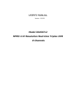
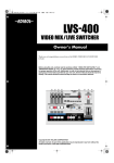
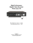
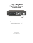
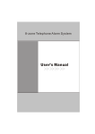
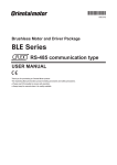
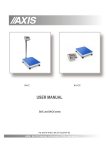
Digital Video Recorder (ATM SERIES) User Manual 1 Operation precautions .......................................................................................................................3 1. Installation environment........................................................................................................3 2 Open Product box and Check the accessories........................................................................3 Chapter 1 Product Features and Specifications............................................................................4 1.1 Product Specifications.........................................................................................................4 1.2 Main Features......................................................................................................................6 Chapter 2 Operational manual before installation........................................................................8 2.1 Check unpacked DVR.........................................................................................................8 2.2 Installation precaution......................................................................................................8 2.3 Connection of video/audio input/output...........................................................................9 2.4 Connection of alarm input and output devices..................................................................11 Please short connect between the alarm input end and the power ..................................12 2.5. Select and configure recording mode............................................................................13 2.6. Network connection .........................................................................................................14 Chapter 3 Installation .................................................................................................................15 3.1. Hard disk installation .....................................................................................................15 3.2 Front panel introduction..................................................................................................16 3.3 Keys functions.................................................................................................................16 3.4 Mouse operation................................................................................................................17 3.5 Back panel introduction ....................................................................................................18 Chapter 4 System operation .........................................................................................................20 4.1. Turn on / off the recorder .................................................................................................20 4.2 Recording operation ..........................................................................................................21 4.3 Playback..............................................................................................................................24 4.4 Back up .............................................................................................................................26 4.5 Pan-tilt control and image color control............................................................................27 Chapter 5 Menu operational guide.............................................................................................31 5.1 Menu structure ..................................................................................................................31 5.2 Menu Overview.................................................................................................................32 5.3 Menu operation .................................................................................................................34 Chapter 6 Operation over Network ..........................................................................................40 6.1. Network connection operation .........................................................................................40 6.2.Login and logout ...............................................................................................................40 Chapter 7 Serial port operation ..................................................................................................52 7.1 Control Keyboard..............................................................................................................52 7.2 Matrix connection .............................................................................................................53 Chapter 8 Frequent Questions and Answers ..............................................................................54 2 *Operation manual for MPEG4/H.264 series ATM DVR* *this manual takes DVR0304MBD as an example* Operation precautions All the safety and operating instructions should be read before the appliance is operated. The improper operation may cause irreparable damage to the appliance. 1. Installation environment 1.1 Keep away from extreme hot places and humid places 1.2 Avoid direct sunlight 1.3 Be horizontally installed 1.4 Avoid violent vibration 1.5 Do not put other devices on the top of the DVR 1.6 Put in well ventilated place, do not block the radiator fan 2 Open Product box and Check the accessories Check the following accessories after opening the case: * the packing list in the box is the final * 2.1 One power cord. 2.2 One Ethernet cable (positive cable), one serial port cable. (CIF 16-ch is not provided with the serial port cable) 2.3 One package of installation kit. 2.4 One user’s manual. 2.5 One CD for installation. 2.6 Certification of the product. 2.7 One 25-pin alarm converter. (CIF 16-ch is not provided with the converter) 2.8 One mouse. 3 Chapter 1 Product Features and Specifications 1.1 Product Specifications Model DVR0304MBD LCD YES Processor High performance industry level embedded microprocessor Operation System Embedded Linux operation system System Resources Multi-task operation: multi-channel recording, playback and network operate simultaneously Interface User friendly graphical interface Input Devices Front panel, USB mouse, remote control and network simulator Input Arabic numbers, English and Chinese (optional) Shortcut Copy/paste operation, USB mouse right-key shortcut menu and USB mouse screen switch function Video Compression MPEG4/H.264 Audio Compression PCM Video Input 3CH composite video input: (NTSC/PAL) BNC (1.0VP- P, 75Ω) Video Output 1 PAL/NTSC BNC (1.0VP- P, 75Ω) composite video output, 1 VGA output; Video Standard PAL (625 line, 50f/s), NTSC (525 line, 60f/s) Recording Speed Real-time mode: PAL 1f/s to 25f/s per channel and NTSC 1f/s to 30f/s per channel Non-real-time mode: PAL 1f/s to 6f/s per channel and NTSC 1f/s to 7f/s per channel Display Resolution (PAL/NTSC) 1/4 windows Realtime: CIF 352×288/ 352×240 Playback: CIF 352×288/ 352×240 Motion Detection 192 (16×12) areas configurable; multi-level detection sensitivities Image Quality 6 level image quality Area Covering Random size selectable for protected area coverage Image Information Channel information, time information and protected area coverage information TV Adjust Auto-adjustment for anamorphic images; luminance and contrast configurable Screen Lock Specific display screen lockable (blue screen covered for unauthorized users) to ensure data security Channel Channel name, recording status, screen lock status, video loss status and motion detection status Information shown on the bottom left of display screen Color Configuration Hue, luminance, contrast, saturation and signal gain configurable for each channel 4 Audio Input 3CH audio input: 200-1000mv 10KΩ(BNC) Audio Output 1CH audio output: 200-3000mv 5KΩ(BNC) Hard Disk Supports up to 2 large capacity HDDs Hard Disk Consumption Audio: PCM 28.8Mbyte/Hour Video: 56-900Mbyte/Hour Hard Disk Hibernating function for non-working HDDs to reduce power wastage and extend life-time of Management HDDs Recording Mode Manual, motion detection, schedule and alarm recording Recording Duration 1 to 120 minutes single recording duration configurable (default 60 minutes) Overwrite/Sto p Mode Record Search Playback Overwrite mode and stop mode selectable when hard disk is full Search record by time, type and channel Multiple playback mode, multi-level fast-forward, multi-level slow-forward, single frame playback etc Multi-switchin g Switch to previous and posterior record Switch to another channel record of the same time Play Mode records continuously (auto-play recordings of the same channel one after another) Multi-channel Playback Display Zoom Selective Enlargement 1 channel, 2 channel or multi-channel playback for specific mode Split/adaptive/full screen for multi-channel playback Selective enlargement when in full screen mode Backup for HDDs Backup Mode External USB storage devices (USB flash memory, removable HDD, USB CD-RW/DVD-RW) IDE CD-RW/DVD-RW / DVD-RW Network download and backup Network real-time monitoring DVR configuration through client-end and Web browser DVR update through client-end and Web browser Checking video loss and alarm information through network PTZ control through network Network Control Record download and playback through network Multi-DVR networking via Central Management Software Duplex transparent serial port Network alarm input and output Voice dialog Multi-screen preview Video Loss Relay external alarm output and dialog box popup External Alarm Relay recording, external alarm output and dialog box popup Manual Alarm Enable and disable alarm input Simulate alarm signal to alarm output channel Control 5 Alarm Input 4 channel grounding alarm input Alarm Output 3 channel relay output (1 controllable +12V output) Alarm Relay 30VDC 2A,125VAC 1A USB Port Connect with external USB devices Network Interface RJ45 10M/100M adaptive Ethernet port RS485 PTZ control interface, multiple protocols supported RS232 Common serial port, keyboard interface and transparent serial port Hard Disk Information IDE interface status, HDD information, working HDD number Bit Rate Stat. Bit rate statistic of each channel; bit rate waveform display System Log Up to 1024 system log; search log by time and type System Version Recording channel number, alarm input/output channel number, system version, release date etc Online User Online user display User Management Multi-lever user management; united management for local user, serial port user and network user, user power configurable Support adding user and group, and changing of the power (no quantitative limitation) Password changeable; administrator can change passwords of other users Password Protection Update Accounts lock: 5 password input trials limitation in 30 minutes Web browser, client-end and specific update tool USB flash memory update (optional) Login by user name and password to ensure security Login, Logout and Shutdown Power Supply Power Consumption Working Temperature Working Humidity Working Atmosphere Size Installation Mode Logout, shutdown and restart selectable when shutdown Shutdown power configurable 220V+25% 50+2% Hz / 110V 60Hz 35W 0℃ - +55℃ 10% - 90% 86kpa - 106kpa 200mm*130mm*270mm Normal installation and rack installation 1.2 Main Features Note: Features may differ due to different model and hardware/software version. • Analog video output port and VGA port enable real-time monitoring, TV output for CIF series DVR • 1/4 window monitoring Real-time Monitor • Display of real-time bit rate and hard disk consumption • Information of recording, motion detection, video loss, screen lock and etc. • Local view of system log • Video Compression: MPEG-4/H.264 Compression Mode • 1/2/3 CH video compression and real-time hardware compression for each channel 6 • • • Storage • • • Backup • • • Recording and Playback Network Operation Alarm Relay Communication Interface Pan-tilt Control Intelligent Operation • • • • • • • • • • • • • • • • • • • • • • Real-time synchronization for audio and video 1 built-in IDE port and supports up to 2 large capacity HDDs(expansive support 4 HDDs) Hibernating function for non-working HDDs accepted to reduce power waste and extend HDDs life time Overwrite mode and stop mode selectable when hard disk is full Special storage format for data security IDE port (hard disk and IDE CD-RW) backup and USB port (USB flash memory, USB removable Hard disk and USB CD-RW) backup Download and backup through network Multi-task operation: real-time recording, single channel playback, remote monitoring, records search and etc. Multiple recording mode: manual recording, schedule recording, alarm recording, motion detection recording (pre-recording for alarm recording and motion detection recording) Record playback through network Fast classified record research function Multiple playback mode: fast-forward, slow-forward, single frame and backward Display of accurate recording time Selective enlargement under full screen mode Remote monitoring Pan-tilt control Record search and playback DVR parameter configuration and software update Remote alarm management and system log search Embedded TCP/IP protocol enables Web browser control Multi-level user management; power configurable for different user and group 4 channel grounding alarm input for CIF series; video loss alarm and motion detection alarm supported; panalarms includes smoke detector, thalposis detector, IR detector and etc. Multi-channel relay output, enables alarm relay and onsite lighting control Protective circuit for both alarm input and alarm output Special interface for alarm input and pan-tilt control One RS232 port used for keyboard expansion, normal serial port, matrix control and etc. One RJ-45 port for network control Support pan-tilt decoder using RS485 port Multiple decoding protocols expandable for pan-tilt and speed dome control Mouse supported Copy/paste function 7 Chapter 2 Operational manual before installation Note:For installation, please refer to the related national construction standard. 2.1 Check unpacked DVR 2.1.1 Open the box When you receive the DVR from the transportation corporation, the first thing you have to do is to check if there is any apparent damage to the appearance. The protective materials used for the package of the DVR can handle most accidental clashes during transportation. Then open the box to check the accessories. Check the items against the list on the warranty card. After that you can remove the protective layer of the DVR. 2.1.2 About the front panel and the rear panel Various key functions on the front panel and various interfaces on the rear panel are introduced in detail in the instruction book. Please check the model on the front panel against your purchase contract carefully. The tag on the rear panel is very important to our after-sales service. Don’t tear it up or discard it (otherwise we won’t provide warranty service).When you call our company for after-sales service, we always need you offer the product’s serial No. 2.1.3 After open the outer cover, you should check: Besides checking apparent damages, please check whether there is any loose connection between the front panel’s data ribbon, power cable, the cooling fan’s power line and the mainboard. 2.2 Installation precaution Please heed the case earth of DVR. 2.2.1 Install HD At the first installation, make sure whether the HDDs are installed and right jumped. 2.2.1.1 How to choose hard disks High speed HD 7200 rpm or plus is strongly recommend. About brand, Maxtor HDD is strongly recommended. 2.2.1.2 How to choose HDD size 1、 Single HD size For single HD, the user can use 10G-infinite HD, but for better stability, 120G-250G HD is recommended. 2、 How to calculate the total size of HDDs The computing formula of total HDD size is: The total size(M) = channel numbers * recording hours * HDD used per hour(M/h) So we can get the computing formula of recording hours: 8 recording hours= the total size (M) HDD used per hour (M/h) DVR adopts MPEG4/H.264 compression technology. This technology will produce considerable dynamic range when compressing data. So when you calculate the total HD size, you should estimate the average HDD size per hour per channel. For example: For 4-ch DVR, the average size of HDD used per hour per channel is 200M/h. Now if you hope the DVR can record for 30 days with 24 hours one day, the total size of HDD needed is: 4 channels * 30 days * 24 hours * 200 M/h = 576G. So you need install five120G HDD s or four 160G HDDs. 2.2.1.3 HDD installation (see chapter 3 for installation diagram) Data ribbons, fastening screws and humanistic HDD shelf design are already provided in the accessories to benefit you to install HDDs. One point you should take special attention is about HDD jumper wire: If only one HDD is connected to an IDE port, you should set the HDD to MASTER. If two HDDs are connected to one IDE port, you must set one as MASTER and the other as SLAVE. Please don’t set HDD as CS Enable or Cap Limit. After HDD installation, please check connection of data ribbon and power cord, then mount the outer cover. 2.2.2 About CD burner 1.ATM DVR supports IDE port and USB port. ATM DVR supports USB port. If you use IDE port to connect CD burner, you’d better set the jumper as MASTER. 2. You’d better use our company’s already tested brands. You can consult the technical support or visit our website for details. 2.2.3 Connection of exterior power supply Confirm the right position of the toggle switch near the power socket according to the input voltage. We recommend you use stable and less wave interference power supply that will benefit steady operation and useful time of DVR. It also benefits operations of other peripheral equipments such as cameras. If possible, UPS power is the best choice. 2.2.4 Install DVR in the machine cabinet The size of DVR is,200mm (Wide)x130mm (Deep)x270mm (High) Put the cabinet in ventilated place. Avoid extreme heat, humid and heave dusty conditions. After long time use, you should clean inlet opening, cooling fan etc. with a soft dry brush. 2.3 Connection of video/audio input/output 2.3.1 Connection of video input The video input interface is BNC. The request of video input is PAL/NTSC BNC(1.0VP- P , 75Ω). The video signal should comply with national standards. High SNR, low distortion, low interference, natural color and suitable lightness are also needed for the video signal. Guarantee the stability and reliability of the camera signal: The camera should be installed at suitable place. Under backlighting, low illumination surroundings that are not suggested, the user should use backlighting compensation camera or low illumination camera. 9 The power supply of the camera should have the same grounding with the power supply of the DVR to ensure the normal operation of the camera. Guarantee stability and reliability of the transmission line Use high quality, good shielded BNC and choose suitable BNC model according to the transmission distance. For too long distance, you should use twisted pair, add video compensation devices or use optical fibre transmission to ensure video quality. You should keep the video signal away from the strong electromagnetic interference, especially the entry of high tension current. Keep connection lugs in well contact: The signal line and shielded wire should be firm and in well connection. Avoid dry joint, lap welding and oxidation. 2.3.2 Audio input HD1 4/8-ch use BNC. 16-ch uses RCA audio cable via a 25-pin tieline. ATM SERIES use BNC. Due to high impedance of audio input, you must use active sound pick-up. Audio transmission is similar to video transmission. Try to avoid interference, dry joint, loose contact and entry of high tension current. 2.3.3 How to choose and connect video output device Video output includes a BNC(PAL/NTSC BNC(1.0VP- P, 75Ω))output and a VGA output. We recommend you use the industrial monitor as video output device. The industrial monitor has the following advantages: 1、 Can adapt industrially long-time monitoring. Ordinary civilian device is easy to age, damage and even burn under long-time playing. 2、 Has higher definition and color recover ability that the civilian device is uncomparable. 3、 Better stability and anti-interference ability, adapt to various complicated surrounding. When pc-type monitor is used to replace the monitor, the following points should be noticed: 1、 To defer aging, the pc monitor cannot be powered on for long time 2、 Regular demagnetization will benefit the monitor to work in normal state. 3、 Keep away from strong electromagnetic interference devices. Using TV as video output device is not a reliable substitution method. The user also need reduce the hours of use and control the interference from power supply and other devices. The hidden short circuit problem of low quality TV may bring damages to other devices. 2.3.4 Audio output The audio output parameter of DVR is 2000mvp-p 1KΩ(BNC). Can connect directly with low impedance earphone, active sound box or amplifier-drive audio output device. If the sound box and the pick-up cannot be separated spatially, it is easy to arouse squeaking. At this time you can adopt the following measures: 1、 Use better sound pick-up with better directing property. 2、 Reduce the volume of the sound box to the value under which squeaking will not happen. 3、 Using more sound-absorbing materials in decoration can benefit to reduce voice echo and improve acoustics environment. 4、 Adjust the layout to reduce happening of the squeaking. 10 2.4 Connection of alarm input and output devices Before connection, please pay attention to the following points: 1. Alarm input a. First confirm if the alarm input is grounding alarm input or voltage alarm input. b. Alarm input: for D1/HD1series, 5~15v is needed for voltage alarm input. For CIF series, grounding signal is needed for alarm input. 2. Alarm output The alarm output port should not be connected to high power load directly to avoid heavy current which will destroy the relay, but you can use the cocontactor to realize the connection between the alarm output port and the load. 3. How to connect PTZ decoder a. Ensure the decoder has the same grounding with DVR, otherwise possible common mode voltage may fail to control the PTZ. Shielded twisted wire is recommended and the shielded layer is used to connect to the grounding. b. Avoid the entry of high voltage. Ensure proper wiring and some thunder protection measures c. For too long signal wires, 120Ω should be parallel connected between A, B lines on the far end to reduce reflection and guarantee the signal quality. d. “485 A, B” of DVR cannot parallel connect with “485 port” of other device. e. The voltage between of A,B lines of the decoder should be less than 5v. 4*. “+12v” output (D1 and HD1 have this output port. CIF hasn’t). Provide the power to alarm device with current less than 1A. 5. Poor grounding of the front-end devices may cause damage to chips. The alarm input type can be Normal Open or Normal Close. Connection socket series: (alarm converter) 1. “Ground”:ground wire 2. “+12v”:Provide the power to alarm device with current less than 1A 3. “OUT 1、2” is two alarm outputs switch(normal open) 4. “485 A、B” is communication connection, used to connect with recorder control devices such as control decoder. 5. “+12(C)” is controllable power output―the third alarm output, is used for standby power for smoke detector alarm device. Dismiss of the alarm needs the device to turn off the power. AB 6. “ALARMIN( 1…4) voltage alarm inputs. Alarm input should be ground 2.4.1 Instructions about alarm input end: 1、Alarm input: 11 ·4 channel alarm inputs (Both Normal open and Normal close type) · Please short connect between Please short connect between the alarm input end and the power the connection end of the alarm device +12V GND ◎ ◎ COM end and GND end. Com ◎ NC ◎ The connection ·Please parallel connect the Ground of the DVR with the ground of the alarm detector ◎ALARMIN ┇ ·Please connect the NC port of the alarm sensor to the DVR alarm of the DVR end ◎GND +12V GND input(ALARM) ·If you need to restore the touched-off alarm remotely, you have to supply the controllable 12 V power of the DVR to the alarm detector, such as the smoke detector. 2.4.2 Instructions about alarm output end: 2 ways relay alarm output (normal open contacts). Should provide the power supply to the alarm detector. To avoid over loading, please read carefully about the related parameters of the relay. (See below table) The controllable +12v can provide the power for restorable smoke detector. 2.4.3 Relays’ parameter of the alarm output end Model: JRC-27F Material of the Sliver contacts Rating(resistance Rated switch capacity 30VDC 2A, 125VAC 1A load) Maximum switch power 125A 160W Maximum switch voltage 250VAC,220VDC Maximum switch electric currency 1A Between touches with same 1000VAC 1minute 50/60Hz Insulation polarity Between touches with different 1000VAC 1minute 50/60Hz polarity Surge voltage Between touch and loop 1000VAC 1minute 50/60Hz Between touches with same 1500V (10×160us) polarity Length of open 3ms max time Length of close 3ms max time Longevity Temperature Mechanical 100×106 times (10Hz) Electric 200×103 times (0.5Hz) -40~+70℃ 12 Supplementary: the definition of 25-pin RS485 port (for D1 and HD1 series) The 25-pin RS485 port is for realize pan-tilt-zoom control; enables the triggering of Alarms. RS485 connection can control various pan-tilt-zoom decoders, and the specific type of the decoder can be selected in the setting in the menu. Switch out pin number is marked on DB25 plug. The definition of the pin is as below.(The broken line in the graph means being connected inside.) Alarm input ALARM1 ┆ ┆ Alarm output ALARM8 ALARMOUT1 Controllable +12V output ALARMOUT2 120 Ω +12V output Combined as RS485 B line (suggested) Combined as RS485 A line A Earth line B A Decoder a) 1、14、2、15、3、16、4、17 connects to alarm input: ALARM1~ALARM8; b) 5、18-OUT1,6、19-OUT2 two linked normally open output: c) 7、20-OUT3 are connected inside,either is controllable +12V output; d) 8、9、21 are +12V power output, able to be as the power supply for alarm sensors; e) either pin of 10、22 is the B line of RS485, either pin of 11、23 is the A line of RS485; f) 12、13、24、25 are earth lines. 2.5. The DVR can provide multiple recording modes. The user should select and configure the recording mode due to actual need. To get the best balance between the recording time and HDD space used, the user should pay attention to the following points: 1、 The recording period for the motion detection or alarm recording can not overlap with the schedule recording. 2、 Under poor illumination, the user should avoid to use motion detection recording. He had better use more stabilized alarm recording with linked light control to assure the recording quality and rational use of HDD. 3、 The sensitivity of motion detection should be adjusted according to spot environment test to avoid to false report or fail to report. 13 B Decoder Select and configure recording mode resistance 2.6. Network connection DVR provides a standard RJ45 port and embedded TCP/IP protocol to connect LAN or Internet. During constructing a LAN, please use switch instead of HUB guarantee adequate bandwidth and avoid too long wiring distance. Please choose suitable bandwidth access mode. Ethernet cable should be made according to standard. Note: Please apply this manual to the right models. It is prohibited to use this manual to install or operate other manual. 14 Chapter 3 Installation 3.1. Hard disk installation Please check whether HDDs are installed at the first use. Up to eight 10G-infinite capacity hard discs can be installed internally. Installation steps ①Remove the screw ④ Install first HDD ensuring bracket is in correct position ⑦Connect the HDD to the IDE port via the data communication cable ②Remove the cover ⑤Install second HDD ⑥Screw the bracket ensuring bracket is correct 1 ⑧Connect the power cord to the HDD Note:Connect USB mouse, USB storage to the USB port directly. 15 ⑨Replace the outer casing 3.2 Front panel introduction 1. LCD 2. Function assistant 3. LCD power switch 4. Record 5. Up Direction 6. ESC 7. Right Direction 8. Enter 9. Down Direction 10. Left Direction 11. Play last section 12. Slow play 13. Play/pause 14. Fast forward 15. Play next section 3.3 Keys functions No 11 Key name Play last section 12 Slow play Sign Function Play the last recording file before the current I_ Remarks Number 1 file I► 3 levels of slow play speed adjustable: (15f/S - Number 2 5f/S & frame by frame) Play/pause f/ 13 Play/pause When in real time mode, press to enter record search menu Number 3 Direct enter record search menu 14 Fastforward/ 8 Multi-level fast-forward Number 8 16 Number 4 15 4 Play next section Record Play the next recording file after the current file ►I Number 5 Start/stop recording, work with arrow keys or ● Num keys Function Click to display the PTZ and the Image menu under full screen mode Shift the PTZ function menu in Pantilt To enable Cursor field selection with the arrow keys when set the MD area Fn 2 To display the playback state bar during playback Choose/Cancel the backup file when backup To shift the time and HDD information in HDD info menu 6 8 ESC key ESC Enter Direction 9,10 key Number 0 Go back to real time monitor from playback ENTE Enter Cursor Selection R Enter main menu S T 5,7, Escape or cancel Switch the monitor window SNumber 6 Change number TNumber 7 Change setting PTZ control L & R On screen Cursor Control; shifting level WX 1 and level 2 menus; PTZ control WNumber 8 XNumber 9 3.4 Mouse operation *This manual takes right-hander as an example* Besides the front panel and the remote control, the user can also use mouse to operate the menu. Connect the USB port to the USB port of the DVR Click left mouse button The system will pop up a password-input dialogue box if the use doesn’t log in. When in live monitor, click left mouse button to enter menu setting. Clicking a menu icon will enter this menu Execute prompted operation Change status of check box or motion detection area Click number frame or password frame to pop up the number panel Clicking a number on the panel will input this number. Clicking X will clear the input. Clicking √ will confirm the input and close the panel. 17 Click combo box to pop up drop-down list box Double click left mouse button Execute special operation. For example, double clicking an item in the records list will start this record playback. When in multi-windows, double clicking a channel will make this channel display in full screen. Double clicking this channel again will switch back to multi-window status. Click right mouse button When in live monitor, right click will pop op a shortcut menu: multi-window mode(this mode depends on the number of channels of DVR, for 4-ch DVR, only 1-ch and 4-ch are available), Pan-tilt control(the user must set the protocol at first, otherwise related information box will pop up), image color, search, record and main menu. Pan-tilt control and image color only work on the channel where the cursor locates. If in multi-window mode before setting PTZ or image color, the system will switch to single window mode automatically. Cancel the setting and exit the current menu Running steel-ball When inputting numbers in number frame, running steel-ball will increase or reduce the value in number frame. Shift options in combo box Page up or Page down in list box Mouse moving Select the control bar or one option, then move Mouse Left click the menu title bar or playback control bar and drag, after dragging releasing the left button, they will stay in the new position Select motion detection area Click the menu title bar and drag, move the coordinate of the menu. 3.5 Back panel introduction Notes: interrface is a bit different between different models. The actual interface is the final. 18 19 Chapter 4 System operation *Please confirm the HDD to be installed and the proper connection before turning on the DVR* *For the connection method, refer to Chapter 3 ----Installation * 4.1. Turn on / off the recorder 4.1.1 Turn on the recorder Plug in the power cable; switch on the power button at the back of the recorder; power indicator light on; DVR on; default multi-windows for the video output display; If the starting time is within the programmed recording time, the system will start recording function automatically. Corresponding channel indicator lights on and system works in a normal manner. Note: if the system stops during HDD Boot detection, the HDD may not be installed right and please check the HDD connections (Ribbon and Power Connections). 4.1.2 Enter the setting menu After booting up, press Enter (or click the left mouse button), a dialogue box will pop up. Input user name and password to enter the setting menu. You can add or delete customized user groups. There are two default user groups: USER and ADMIN. Ever user in the same group has the same power right. The default password for the USER group is 666666 and the default one for the ADMIN group is 888888. It is recommended that the customized user group have less power right than the administrator group, which will benefit user management. Note:For security reason, please change the default passwords. If you want to add new user group, add new users or modify the related parameters of a user group, you can refer to 。 menu operation——Account。 4.1.3 Turn off the recorder *Please unplug the 220VAC power supply during HDD installation* Press the POWER key on the front panel for 3 seconds to stop the current operations. Then switch off the power button at the back panel of the DVR to turn off the power. 4.1.4 Power off recovery When the power is cut off abnormally, the recorder will recall its last state and continue where it left off. The state indicator light is the same as it was before the power off. 4.1.5 Change the battery of the DVR Change the battery of the DVR, recommend to the same type of Lithium fastener batteries 20 Note: Please check the system time in time and generally change the battery each year to ensure the veracity time. 4.2 Recording operation The user can choose the suitable recording mode according to his demand. When in recording mode, the recording sign will appear on the corresponding channel. 4.2.1 Manual recording ··Press “Rec” button on the remote controller or “●” on the front panel (Need input the administrator password),or under ADVANCED>MANUAL RECORD ··Check the status of each channel in the recording menu. Highlight means the related channel is recording. Button Instructions Display on screen pressing Menu order instruction 2、arrow key Turn recording on ST AND off. Highlight or related means turning on number key recording 3、arrow key Shift WX recording between channels 4、Save Press OK to save the setting ·Turn on recording:When the channel is not recording with“ ”,press the related number key(or useS T arrow key、jog shuttle、mouse)to make it highlighted(“”),then select ONE DAY or PERMANCNE in AVAILABLE WHEN START, ·Turn off press ok to save the setting. recording: press the related number key again(or useS T arrow key、jog shuttle、mouse) to remove its highlight(“ ”). ·Press ESC to exit and OK to save the setting. Select ONE DAY or TRIGGER in AVAILABLE WHEN STOP. Turn on or off recording for all channels: Press ALL to make it highlighted(“”) or remove its highlight(“ ”). 4.2.2 Schedule recording The default recording mode after the starting of DVR is 24 hours continuous recording. The user can choose the suitable recording mode according to his demand.:the details are under MAIN MENU>SETTING>SCHEDULE Schedule Recording Including the settings for General, MD, Alarm recording. Select the related channel in Channel. If you want to set all channels together, choose ‘ALL’. In check box Week day ,highlight means this day has been selected for the setting. (More than one day can 21 be chosen).Prerecord means the system can pre-record from 3sec to 5sec before the action. (The pre-recording time is relevant with bit rate. From Period 1 to Period 6 you can choose the recording period of the current channel for GENERAL, MD or ALARM. You can choose different recording mode during the same period. The six periods should not be overlapped. The time setting scope is from 00:00 to 24:00. After setting all channels, press OK to save. 。Shortcut setting:You can copy the setting of A channel to B channel. For example, in channel 1, after setting, click COPY. Then switch to channel 5, click PASTE. You will find the setting of the channel 5 is the same with the setting of the channel 1. Notes: the shedule sketch picture is shown below the record setting, and the color shows the efficiency of the record type setting. Green means Regular;yellow means MD; red means Alarm. 4.2.3 Motion detection recording When motion detection happens in a channel, the MD sign will appear on the channel. ·Set the motion detection region for the channel. ·Set the related options under MAIN MENU>SETTING>DETECT to start MD recording. Channel: Select the related channel for motion detection Start Record: Select the recording channels when motion detection happens. Alarm Output Starts up external alarm devices which are connected with the alarm relay outputs of DVR when motion detection happens. Delay means to lengthen the recording time when motion detection ends. The scope is from 10 sec to 300 sec. Sensitivity has six levels: 1, 2, and 3,4,5,6. The highest sensitivity level is 6. Video loss: You can choose Alarm Output and Show Message when video loss happens. There is also motion detection Show Message on the monitor. Black detect: Alarm Output and Show Message can also be chosen when the screen on the channel is black because of light, etc. In Region, move cursor to set, and then press ENTER. The setting area has been divided into 192 sections. Green section means the current cursor position, and black section is the armed motion detection area. The blue area is disarmed motion detection area. Press Fn to toggle between armed mode and disarmed mode. When in armed mode, you can press the arrow keys to cover the MD region. After the setting, press ENTER to confirm or ESC to cancel. Before you exit DETECT, you must press Save to save the setting. 22 Prompt: You can use mouse dragging to select motion detection region without Fn key. Right click to exit the region, and then click Save to save the setting. Copy and Paste can be used for the same setting between different channels. 4.2.4 Alarm recording ·See MAIN MENU>SEETING>ALARM Connect alarm sensors to the alarm input port according to the related instruction of Chapter 2 ·Connect the related alarm output(such as light, buzzer, etc.) Alarm Channel Select the related channel (1-16). Type has Normal Open /Normal Close voltage output modes. Start Record select the recording channels when there is alarm input (Can choose more than one channel). Alarm Output Choose alarm output ports when there is an alarm input. The first and second ports will trigger corresponding relay. The third port output controllable 12 voltage. Delay means to extend the recording time after receiving disarmed signal(10、20、30、……90SEC). When the outside alarm is disarmed, the system will extend the recording time automatically before closing alarm relay output. Show message Highlight means display the message for alarm output in the monitor. 23 4.3 Playback 4.3.1 Framework Card number Records Search Enter SEARCH menu Money Amount Type Not used temporary Instructions Display 1、 Press play/pause` on the front panel to enter SEARCH menu. 2、 Click MAIN MENU>SEARCH to enter SEARCH menu. Note:If you have logged out, password should be inputted again. Playback You can search the records according to Type (All, Alarm, Motion detection, All alarm,Card), Channel and Time.,the screen shows the 32 recording files following the searching time. use |W 、X| to page down and page up. You also can use mouse to drag the slide button to view the desired record. Press ENTER or double left click to start the playback. Note:records type:R—general records; A—alarm records;M—motion detection records;C—card records. In ADVANCED>PALYBACK SETTING, Select one channel or two channels. If you choose two channels, two records on two windows are played simultaneously. Card Search:Only card records has been selected,the card input dialogue will popup In the search condition. 24 2 、 Playback status The bar displays Channel No. , date, bar time, playback speed, playback progress. Can control playback speed, sound volume, etc. You can hide the bar by pressing on the front panel or hide icon on the top right corner of the playback status bar. 3 、 Shift to other channel playback during During playback, press numeric key (1 to 16), then the system will start to play the synchronizing records on corresponding channel 4.3.2 How to operate fast play and slow play during playback Button-pressing orders Instructions Remark 1. Fast play: press the During playback press this key to shift Playback speed is relevant key between multiple fast play speeds. to the version Fast play key can be the reverse shift key of Slow play 2. Slow play: press the During playback press this key to shift key► between multiple slow play speeds. Slow play key can be the reverse shift key of Fast play 2、Play/Pause During slow play press this key to shift between play and pause. 3、Play next section, During playback status press to view play last section the next or last record of the same channel. 4.3.3 Jog shuttle special function Jog shuttle special Instruction Remark During playback, turn the outer ring During fast play, press clockwise to change fast play speed play/pause` function 1. Fast play 3. Frame by frame During playback, press Play/Pause, then playback manually turn inner ring of the jog shuttle clockwise twice to switch back to normal play. slowly to start frame by frame playback. Turn inner ring counterclockwise to start I frame playback. 4.3.4 Backward playback Button pressing order Description 25 Remark Backward playback( _ on During playback, click _ to start backward the playback control playback. Click _ again to stop backward playback or frame by bar) playback. frame playback, click X During backward to switch to normal playback Note: 1、During the above operations, the system will display playback speed, channel No. , time, playback progress, etc. on the playback control bar. 2、Some functions depends on the hardware version, such as backward playback, frame by frame playback manually and playback speed. For example, for HD1 DVR, frame by frame playback manually is extensible. Some hardware version may not support some functions or playback speed. The prompt on the playback control bar is the final. You can also consult our company’s technical support. 4.4 Back up The user can back up records through CD-RW burner (extensible for CIF products), USB storage or network. First introduce storage operation through USB port. For network storage, you can refer to the client end operation. 4.4.1Detect device Back-up device can be CD-RW or USB, etc. Immediately checked devices and the total capability can be displayed. 4.4.2Back-up operation Select a device (CD-RW or USB). If you want to clear files on this device, click Clear. Back-up operation: select the device, channel, starting time and ending time, then click Add. Matched records will be displayed. There is a check mark in front of the recording type for every record. You can continue to set searching time and other options then click Add. New matched records will follow already listed records. Click Backup to back up records. If you don’t want to back up a record, you can use Fn to cancel the check mark. The system only backups records with check marks. The screen also displays needed space and free space on the bottom. After clicking Backup, a progress bar will pop up. Note: During backup, you can press ESC on the front panel to exit the screen, but the backup is still going on. If the user does 26 not connect the backup device correctly, the system will display: No backup disk; if the user doesn’t choose records or some errors happen during backup, the system will have corresponding display. Delete backup During backup, the user can cancel backup manually. After clicking Backup, the Backup button becomes Cancel button. Clicking Cancel will stop backup. If the device is USB storage (flash or mobile HD), the records before clicking the Cancel button will be stored in the device. For example, During a 10 minutes long record backup, if it is stopped at the fifth minute, there is 5 minutes long record on the device. For USB CD-RW, if the user cancels the backup, the record on the CD is invalid. The format of the backup record’s name is: CH+ channel NO + date+ time Some tips when using CD-RW to backup records for D1 or HD1 i. Choose CBR mode. ii. Disconnect net to avoid error iii. Recommend to use SONY(IDE brand is CRX230A) and BENQ (USB brand is 5232WI).These two brands have already been tested. Other tested brands are on our company’s website. 4.5 Pan-tilt control and image color control *The controlled camera must be displayed on the monitor in full screen* When in a single window, press Fn on the front panel, PAN/TILT and IMAGE will display on the monitor ·confirm the right connection between PTZ and decoder. Set the proper decoder’s address. ·Confirm the right connection of decoder’s A、B line and the A、B line of DVR ·Set the related options under menu SETTING>PAN/TILT/ZOOM Channel Select the relevant channel. Protocol Choose the protocol of the brand name of corresponding pan-tilt decoder (e.g.: DH-CC means Dahua Decoder). Address is the address of the corresponding PTZ decoder. Baurate Choose the corresponding baud rate of the 27 decoder. Save all the settings and come back to single windows monitor, then click Fn key to set the PTZ-control: Can control the PTZ’s direction, focus, iris, zoom. Can set pre-set position to make the PTZ auto cruising. Pan/tilt/Zoom Note:Grey show for no support function The direction, step, zoom, focus, iris, preset, patrol, pattern, auto scan, aux on, aux off ,auto pan can be controlled. Use the direction keys to set. Select“Pan/tilt/Zoom”,Pop up the menu as picture 1.Support Pan/tilt and lens control. 图1 The pan/tilt support 8 directions: Up、Down、Left、Right、Leftup、Leftdown、Rightup、Rightdown。 (Use the front panel, only Up、Down、Left、Right can be used for direction control) Quick location: In the middle of the direction keys is the quick location key, only the pan/tilt with this protocol can be used and it only can be controlled by mouse. Click and enter the quick location menu. The steps are as follows: click any point on the screen, the pan/tilt will move this point to the center. And zoom function supported in the quick location interface, drag the mouse, and the square made supports 4-16 zoom function. Drag the mouse form up to down, the camera will zoom in; drag the mouse form down to up, the camera will zoom out. The smaller the suare is, the stronger the zoom is. Name Fn key Function Corresponding Fn function Shortcut key Zoom - tele slow play Shortcut key + tele ► Focus - near - close Fast play Last record + far _ Iris Corresponding Next record ► backward + open playback f W Step: The step is mainly used for direction control. If there is a new protocol supporting zoom or iris step, and they can also be controlled.(The value can be obtained through the front panel.(1-8,8 means the biggest). 28 Click set in picture 1 to enter picture 2 and set preset ,patrol,pattern and del preset And so on. 图2 The function options in picture 2 are based on the protocol. If the protocol doesn’t support some functions, the keys will show grey and can not be selected. Click any one of the two buttons(not grey show),it will go to picture 1.You can also press the ESC button on the front panel. Click Page Switch to enter picture 3.There are expansive function. 图3 Support Preset,Patrol,Pattern,AutoScan,AutoPan,Aux On,Aux Off,and LightOn. Notes:The preset, patrol , pattern and ax on/off need values as control parameter, and the parameter here has no value inspection. The first three parameters are set by users, and aux on/off refers to the dome manual. In some conditions, it can be used for special functions. Click Page Switch to enter picture 4. It is the menu of the pan/tilt and also according to the protocol.(Only DH-SD1 and DH-SD2 can enter this menu now) 29 图4 Direction keys are mainly used for menu control. The button will be supported by the protocol. If not supported, it will show grey. Click enter and ESC to enter or quit the menu of the dome. Click Page Switch to return to picture 1. Image Color: Set Hue, Brightness, contrast, Saturation and Gain in different schedule. Notes: the schedule should be 24 hours and the time of 24 times should be integrate. 30 Chapter 5 Menu operational guide 5.1 Menu structure SEARCH HDD INFO BPS INFORMATION LOG GENERAL VERSION ENCODE ONLINE USER SETTING SCHEDULE Main menu RS232 NETWORK ALARM DETECT PAN/TILT/ZOOM DISPLAY DEFAULT ALARM OUTPUT ADVANCED ALARM INPUT DETECT DEVICE BACKUP BACKUP FILES SHUTDOWN MANUAL RECORD ACCOUNT PLAYBACK SETTING 31 5.2 Menu Overview Main menu Remarks Menu level 1 Records search and playback. You can search the records SEARCH according to Type (All, Alarm, Motion detection, All alarm,Card), Channel and Time. The matched records will display on the list. Choose a record and start playback. R-general record A-alarm record、M-motion detection record, Card record INFORMATION HDD INFO Displayed the IDE ports’ state, the total and free space for all HDDs and every HDD, the record starting and ending time The HDD being used will show as ‘*’ following the HDD serial number Press Fn to check the recording time of HDDs Display the HDD information, BPS, Alarm System Display the current BPS and the estimate for HDD space BPS State, occupied per hour, and the Waveform displays the visualized log, Version and etc BPS LOG VERSION Display the important system events’ log Display the information about operation system version, issue date and so on ONLINE USER GENERAL Check online user information Set system time, recording parameter, the machine No., video format and so on ENCODE Set image quality, frame rate, coding style and so on SYSTEM SETTING SCHEDULE Set schedule for General, Motion Detection, Alarm recording. Be able to set 6 different periods everyday Set the system 32 parameter, RS232 image settings, Set the RS232 function and the baudrate parameter Alarm settings, Serial port (RS232) and NETWORK Set network IP address and video data transfer protocol PTZ settings ALARM Set alarm output and the linked recording channels. MOTION See sensitivity, region, alarm output, recording channel, DETECTION video loss and black screen, etc. PAN/TILT/Z OOM Set protocol and baudrate MONITOR Set parameters of menu output and monitor tour DEFAULT Restore all default setting except menu color, language, time format and video format ALARM OUTPUT Manually produce output signal ALARM INPUT Enable/Disable alarm input MANUAL Manually start or end recording ADVANCED RECORD ACCOUNT Add, modify and delete user group and user account. TV ADJUST Adjust the output area size and color 33 AUTO Auto maintenance the selected options MAINTENAN CE BACKUP DETECT Detect back-up devices DEVICE List found devices and display the type and capability BACKUP Back up records on the selected device FILES Pressing Fn can cancel or choose back-up records SHUTDOWN Log out, shutdown system or restart system 5.3 Menu operation *All the below settings of the menu must be saved before taking effect. Include SEARCH, INFORMATION, SETTING, ADVANCED, BACKUP and SHUTDOWN. 5.3.1 SEARCH The menu for record search is as the right picture: Search the records according to Type、channel and time Prompt:Refer to 4.3 for details. 5.3.2 Information 34 Menu of Information see the right picture. Includes 5 section: HDD INFO, BPS, LOG and VERSION HDD INFO Display the information about: State of IDE ports, HDD state, HDD number, HDD capacity, free space, the start and end recording time and so on. The TYPE item has only two options: Read Only and Read/Write. ‘*’ following the HDD number means the HDD being used. ×’means error on the corresponding HDD ‘-’Means no HDD on this port. If the user want to change the error HDD, he must power off DVR first. After DVR start up, if there is HDD collision, the right picture will show up. At this time, the user should check whether there is any collision between system time and recording time (for example: the system time is ahead of the recording time). If it is true, change the system time to ensure the correct recording data. NOTE: Press Fn or left click view recording time to switch to HDD type and capacity. BPS Display the bit rate per second (Kb/s) and estimated HDD space occupied per hour HDD (MB/h)for each channel. LOG Display log information to convenience the user to check the operations on the system. 。 VERSION Display hardware version, the issuing date and version the operation system, etc. The information is read only. 35 of ONLINE USER:Check DVR’s online users 5.3.3 SETTING Menu of the system setting is as the right picture Including: General, Image, Schedule, RS232, Network, Alarm, MD, Pan-tilt, Monitor, Default and so on; Note: Only Administer is allowed to enter the Setting menu. General System Time is used to modify the current system date and time. After the modification please save the change by clicking SAVE on the top right Date Format is for choosing the date format Time Format includes 24 hours format and 12 hours format Language including Simple Chinese, Traditional Chinese and English. In HDD Full, the user can choose Overwrite or Stop mode .If Overwrite is chosen, system will covers the previous recording files Pack every can set the length of each recording file (15mins、 30mins、60mins) DVR No. Setting address here for controlling several DVRs using one remoter Video Standard includes NTSC format and PAL format. Note:System time cannot be changed freely; otherwise it would cause the malfunction of recording search. Encode In Channel, select the related channel. In Compression, choose MPEG4. In Resolution, there are D1, Half D1, DCIF and CIF. (For Half D1 DVR ,only Half D1, DCIF and CIF are available. Bit Rate includes VBR and CBR. In Quality, there are 1, 2, 3, 4, 5& 6 levels of image quality. Frame Rate 1f/s -25f/s is selectable In Audio Encode , If highlighted ,that means audio and video synchronization. Otherwise only 36 video signal will be processed. Cover-Area: In Enable, highlight indicates the user can set the covered area where there is no picture on live monitor or playback. The user can use mouse or the related keys on the front panel to set the area. Schedule Include general recording, motion detection and alarm recording Prompt: Refer to 4.2.2.for details. RS232 Choose the corresponding protocol The available protocols are as below: Console: Used when upgrading and debugging the program through the software Mini terminal Keyboard: Used when controlling DVR by Dahua special keyboard BAUDRATE: Choose the corresponding baud rate. DATEBIT: From 1 to 8 STOPBIT: Has three options: 1, 1.5, 2 bits VERIFY: Including Odd, Even or None. IP ADDRESS is set by using ST or input Network the exact numbers to change the IP address (IP address can only be set in this option) Then set the related Subnet Mask and Gateway HTTP: default 80 TCP: default 37777 and can be changed if needed Protocol Choose TCP. In Max Connection, the user can choose from 0 to 10. 0 means online users are not allowed. Up to 10 online users can visit the DVR simultaneously. Alarm: Refer to 4.2.4 for details. DETECT:Refer to 4.2.3 for details. PAN/TILT/ZOOM: Refer to 4.5 for details. Display In GUI and Monitor, the user can choose the favorite background color and the transparency as well. 37 The transparency can be chosen from 128 to 255. Time Title: If highlighted, the system time will be displayed on the monitor. In Monitor Lock, highlight means the live monitor of the corresponding channel has been locked. Only the users who have the right to view the channel can see the picture. The view right setting is under ADVANCED> ACCOUNT. Monitor tour Set the tour interval (from 5 sec to 120 sec), display modes (l, 4, 9,16 windows), attended channels (Highlight means attend the tour) for the tour. Defaul t setting The system will restore the original factory default 5.3.4 Advanced Menu of the advanced setting is as the right picture: Including Alarm output, Alarm input, Manual record, Account, Playback Setting Set the alarm output ports. Highlight means Alarm Output enabled. Click Ok to save, Cancel to cancel the setting and exit. Manually open/close the related alarm output port. Set the alarm input port and highlight means Alarm Input enabled Click Ok to save, Cancel to cancel the setting and exit. Only when the alarm input is enabled, the DVR can receive the corresponding alarm input. Manual Record Account Refer to 4.3 for details. Manage users account The system adopts two levels users management: group and user. Different group should have different name. So should user. Every user must and only belong to a group. Three times password failure will sound the buzzer for 5 seconds. Five times failure will lock the user. After 30 minutes, the locked account can be used again.。 38 Add group Enter Add group, then input group name and select 48 rights which include Control Panel, Shutdown the device, Monitor, Playback, Record, Backup, Hard disk Management, Pan/Tilt//Zoom, User account, Query System Info, Alarm I/O Configuration, System Configuration, Query Log Info, Clear Log, System Update and Control the Device. Modify Group: Modify the attributes of a group. Add User: Enter Add User. Input user name and password, then select your group. Once you choose the group, your rights are below the rights of the group. 5.3..5 Backup Menu of Backup is as the right picture Including: Detect Device and Backup files Refer to 4.4.2 for details. 5.3.6 Shutdown Logout menu user: exit menu, the user has to input the password for entering menu. Restart application: exit application and restart application. Shutdown: exit and power off DVR. Restart system: exit and restart system. 39 Chapter 6 Operation over Network 6.1. Network connection operation . Confirm the right connection between the computer and the DVR . Set IP address, subnet mask and gateway to the computer and the DVR. (If there is no router on the network, please assign IP addresses within the same network segment. If there are routers, you should set the related gateway and subnet mask. The network setting of DVR is under SETTING>NETWORK. · Use ping ***. ***. ***. ***(IP address of DVR)to check the link of the network, replied TTL value less than 255 is normal. · Open IE browser and input the IP address of the DVR you want to log in · The web server can be recognized and downloaded automatically. When upgrading the web server, the old one will be deleted. 6.2.Login and logout Please input the IP address of the DVR in the address column of the browser. Take the DVR’s IP address: 10.1.28.240 as an example: Input http://10.1.28.240. Note: The first time you visit this DVR, the system will pop up a dialogue box to ask ‘Do you want to install and run http://10.1.27.240/webrec.cab?. Please choose Yes, then the system will install the software automatically. Before logging in,click the right mouse key and the following menu displays Select uninstall webrec.ocx , the system will delete the web server automatically 40 . On the remote monitor display, there is a monitor video window, with selection choices: login、 logout、video、search, config(system setting)、Assistant(assistant setting) and so on. Login:Click login, and the following dialogue box (6-2) will pop up. Input username and password. There are three types of users: Administrator, User, Guest. For the detailed information please refer to User manage in Assistant setting. The default username is admin and password is admin For Security purposes, please change the administrator password in time. 41 If after the input of the username and password, the following box pops up. The system is indicating that another user has used this name and logged in. Please use other name to log in. If after the input of the username and password, the following box pops up(6-4). The system is indicating that the username or the password is incorrect please try again. Log out: if the logged in user need to log out, please click logout button. After the popup of the following dialogue box, please choose Yes. See 6-5. 3. Operation of the right key menu After you log in as Administrator, the buttons like login、logout、search, config and Assistant are activated. Click the right key and the following interface will show: 42 If the DVR is 16 Channel, the real-time monitor will show 16 channel options; if 4 channel, it will show 4 channel options. The right key menu includes: Real time monitor, Multi-Video Preview, Decode quality, Playback Control Bar, Pan-tilt Control, Net Data flux, Full Screen, ResizeVideo, Video Windows, Restore Zoom In and uninstall webrec.ocx. Video: The same function with the right key menu Real time monitor:Among the displayed channels, you may select the channel you want to see. Channel name can be changed under Assistant->Change Name. When you view picture, click the right key and you will find a menu option ‘prearrange set’ has been added Note: If you didn’t set a protocol of the pan-tilt on the DVR configuration menu, the prearrange set and Pan-tilt Control options are gray and can’t be set. If you did set a protocol and the options were still gray, maybe you have no administrator right or were deprived of the right. Please apply for the control right first. Decode quality: 4 levels decode quality for choose Playback control bar:Used with records search. Pan-tilt control:Control the moving direction of the pan-tilt, zoom, iris and focus of the lens. . Press the related buttons to control. Note:Before the PTZ will operate, you must set the right protocol of the pan-tilt-zoom 43 Prearrange set:Move the camera to the prearranged position, then preset the position. Several positions can be chosen. If the check box near tour checked, the PTZ will cruise automatically between these positions. Pan-tilt Params Set: The step is mainly used for direction control. If there is a new protocol supporting zoom or iris step, and they can also be controlled.(The value can be obtained through the front panel.(1-8,8 means the biggest). Net data flux:Display the statistics of the network transmission data flux. When there is no network data transmission the statistics shows zero. Full screen:There are two ways to realize full screen monitor: One is to double click the window directly; the other is to select Full screen among the right key menu. During multi-window state, choose one of the windows and make it full screen in the same ways. Resize Video:In single window status, the user can resize video only when live monitor is chosen. In multi-window status, video can be resized even without live monitor. Video windows:There are One window, Two windows, Four windows, New video window, Close video window and Arrange in full screen New video window:When the number of video windows is less than 4, you can add new video window manually. Close video window:Close the video window. Arrange in full screen:If two or more windows are displayed, you can use this option to display multi-window in full screen Uninstall webrec.ocx:Uninstall the Active X webrec.ocx. before you upgrade the new web Active X 4.Records Search 44 Click on search, then fill in the required info on the pop up dialogue box of records search Input recording time, channel number and searching type (Record ,Alarm or Motion detection), and the results will show in the dialogue box. It only shows the 15 records after the searching time and clicks Page up and Page down to find the right records. Double click the wanted record, and system will play the selected record, which can be played at full screen. At the same time you can also perform records download, and the record will be automatically saved at C:\Download. Save record stop save capture picture full screen During the playback, you can operate the buttons in the playback bar like save record, stop save, capture picture, full screen. During the playback on the video screen the video displays the channel number, time and data flux of the record. Download:See 6-12, select the wanted records (It supports the downloading of several records simultaneously) and click Download. A save window opens The default format of the downloaded records’ names is as: file name +Channel N +date +time,extension name is .mp4(Example: a-0120021205071028.mp4, 01 means channel 1, 20021205 means December 5th of 2002, 071028 means 7 o’clock 10 minutes 28 seconds). If you want to download several records together, you should check in the check box before download together. The default name of the records is the same with the name of the first record.(according to recording time). During the playback, it will play all the records. Saved under Download file clip. Input the file name and choose Save. The screen shows the processing of the downloading until the completion. 5. Config (System setting) Click Config button,and pop up the dialogue box. There are General、Schedule、Image、Alarm、Motion detection Video 45 parameter tabs of six setting menus. Note:The gray part of the menus that cannot be changed can only be modified directly at the DVR. General:Include the recording length setting. In Control Column select the channel number and its pan-tilt decoder’s protocol, as well as the related address so as to realize the control of the lens and pan-tilt. Schedule:Able to select the different channel and date to perform the recording at the different period of time. Schedule recording includes general recording, motion detection recording and alarm recording. There are six time periods for setting in each recording type. The set time in general recording are independent with the set time in Motion detection and alarm. Only when status is On, the set time period takes effect. If the states of the two time periods are both Off, the system will not record in this recording type. Image:This menu can select the coding style, image quality and protocols for each channel. After finishing one channel setting, click Save to save the setting of this channel. You can continue to set the image attributes of other channel. Finally, click Save on the bottom of the dialogue box to save all setting. Frame rate has 1f/s、2f/s、3f/s、6f/s、12f/s、20f/s. Coding style has VBR(variable bit rate) and CBR. When in VBR 46 style, there are 1,2,3,4,5,&6 levels of image quality. When in CBR style, selectable data flux are 128Kb/S, 256Kb/S, 384Kb/S, 512Kb/S, 768 Kb/S, 1024Kb/S. The different data flux demands on the related bandwidth and the transmission image quality is also different. Among them Level 6 demands on the widest band and has the best image quality. Alarm when video lost: Off means no alarm. On means alarm when video lost Alarm:When there are alarm input signals, the user can select the recording channel and the output port. In Alarm Port, the user can choose from 1 to 16 or ALL. Record Channel means when there is an alarm input at an alarm port, the system can start up recording at the corresponding channels which have check marks in the check boxes. After setting one alarm port, click Save Port to save the setting. After setting all ports, the user should click Save to save. Motion detection:When the user set the time period for motion detection (the time period can not overlap with the time for the general recording. The general recording has higher priority), motion detection will take effect. The purple area is the selectable motion detection area. User can move the cursor to choose the area and can also set the sensitivity of the area due to the need. Click Full screen or press right key on the area to display the motion detection area at full screen. After setting the area the user can Save channel or Clear the area. Alarm Output:This field allows the user to activate an output relay. If you want to set this channel fully as motion detection recording, you have to turn off the timing recording of this channel. Video parameter User can adjust the video Hue, Contrast, Brightness, and Saturation and so on. Click Reset to reset default value 47 . 6. Assistant Assistant :Click on Assistant button, as following, there are User manage, Record control, Apply for control right, Log information, System information, Alarm prompt , Channel name, Upgrade BIOS and About User manage:Display users’ information. The right buttons can let an administrator user save, add, modify, delete and cancel the information. Three levels users:Administrator―fully set the system and modify the user information; User―can not set system parameter and modify other users’ information; Guest― can not set system parameter and records search, can only modify personal information. 48 Add:Click Add to show the following dialogue box: User can add user information in this dialogue box, assign user power level. There is only one administrator allowed. Modify:Select this button to show the following. User modify the filled-in information. Record control:Control the recording of each channel manually. Apply for control power:Web client software can supply the login of multiple users. If you want to have the control power, you can click this option and confirm to have the control (6-27). If the user want to have the control power, he has to apply and gain the authorization of the user with control power. If the logged-in users are all normal user, the first logged-in user gains the control power automatically. If Administrator logs in later, he or she can gain the control power by force. If only one user logs in or the logged-in user is the user with control power, the box is gray. The following picture is other user is sending request to the user with control power. 49 Log information:The operations on the system are all recorded in log information. System information:Check the basic information of the system. When sound is not needed, you can turn off the audio. Due to the band width consideration, the user can select the different Video transport mode, and after choose non-real-time transmission; the mode is Extract I frame. Video type PAL or NTSC has to be selected right. If Auto recycle monitoring is on, system will shift among all the channels automatically and the time interval can be set. Alarm prompt: Different sound warning for the certain Alarm input can be chosen according the user’s needs. The audio file named Alarm Sound. wav in under the directory System32. Channel name:Able to name each channel and the letters are no more than 12. The revised channel names will be displayed on the screen. The default setting of the channel name is Channel No.1 to Channel No.8. 50 Upgrade BIOS: Able to upgrade the BIOS program remotely. Open the related BIOS or Web file and click on the related button (the system can recognize the file type. After the upgrading, it will show the clue about the upgrading. About:Version information 51 Chapter 7 Serial port operation 7.1 Control Keyboard The keyboard can control multi-DVR, set up menu options to one DVR or multi-DVR and control PTZ. Choose Keyboard in Function under DVR menu SETTING>RS232 and set the related parameters which are the same with the keyboard. DVR can be connected to keyboard’s RS232 port directly, but the distance should be less than 10 meters. If using RS232 ports, the keyboard can only connect to 2 DVRS. If we want to one keyboard to control more than 2 DVRS, we must use RS485 ports and RS485-RS232 converter. The distance between RS-485 and DVR can reach 1200 meters. Set different address to every DVR. When you use the keyboard to control one of recorders, you have to input the address first. After all the setting, you can use the keyboard to control the DVR or set menu options. Note:The keyboard works only when the ACT light on the front panel of the DVR is on. 1)By RS232 serial ports: 232communication cable Connect To DVR Directly Recorder Recorder The remote address of every recorder can be set freely, but 255 is the maximum. Each address should be different. More details can refer to recorder manual 52 2)By RS485 serial ports: A B 485&232converter 。。 。 Two 485 buses 485&232converter One 485 bus can connect up to 32 converters recorder 。。。 recorder Each converter can connect up to 12 recorders 7.2 Matrix connection DVR can also work with Matrix through RS232 port. Before connection, you should consult your supplier whether DVR has the matrix control protocol. After connection, choose the corresponding matrix protocol under SETTING>RS232, you can use the front panel of the DVR or remote control to control the Matrix. 53 Chapter 8 Frequent Questions and Answers 1. If the operation system is WINDOWS98, which aspects should be taken care of? For WINDOWS98, a picture tool DIRECTX 7.0 should be installed in advance, because WINDOWS 2000 or XP already includes this tool. 2. 3. HDD can not be detected. z First check whether the HDD is broken z Check whether jumper line, IDE data ribbon and power cord are well connected z If only one HDD is connected to one IDE, this HDD must be set up as master What is mean for the sound of buzzer when normally start the machine When the machine is started successfully, it would burst out a short ring. When the HD could not be identified, it would burst out a long ring. When communicate with the controller panel is abnormal, it would burst out a voice of one long ring and two short serially. 4. Uncontrollable the recording time? The recording time unit is one day. Besides schedule recording, there are other recording modes such as motion detection recording, manual recording, alarm recording. Please confirm each setting is correct. Each time period should be set within one day. 5. The indicator light is flashing while recording? Check the external video input signal first. When substandard signal is inputted, the indicator light will flash. Otherwise the reading speed of HD is too slow will cause the problem, in this case, the current HD should be changed. 6. About heat dispersion We use low power dissipation chips for DVR internal circuit. Smart management is adopted to manage HDD. If we haven’t manipulated DVR for 7 minutes, DVR will make non-working HDD into standby mode. This reduces heat volumes of DVR and also improve useful time of HDD 7. No video signal on one channel on the monitor Check whether the video line is well connected. Or put the camera’s video line into the monitor directly to see if there is any video signal. If not, that indicates that there are some problem for the camera or video line. If the picture shows up on the monitor, please contact with the supplier. 8. Remote control doesn’t work Most of the cases fall into two reasons: battery problem or address mismatch. Battery Problem: Make sure that two good AAA type batteries are installed. Address Mismatch: one remote control unit can be used to control multiple DVRs. Each DVR is programmed to accept control signal from one of 256 channels. This setting can be found under MENU->SYSTEM SETTING ->GENERAL-> REMOTEADDR. To change the output channel of the remote control unit to match one particular DVR (represented by Channel # 1 to 256), aiming 54 at the DVR, press the “ADD” button which is located at the right upper corner of the remote control. There should be a message displaying on the local monitor “ADDRESS _ _ _”. Use the remote control’s numeric keys to input the DVR’s channel number and press the ENTER button. If you cannot get the “ADDRESS _ _ _” message and the connection of the local monitor is correct, please call your vendor for support. 9. Can’t control PTZ or speed dome z Check the connection between the DVR and PTZ or speed dome z Check the setting. The setting can be found under MENU->SYSTEM SETTING->PTZ CONTROL z The address and protocol should be matched with ones in PTZ or speed dome 10. Fail to connect to network z If the ‘fail to connect to one IP address’ dialog box pops up, the system is indicating that there are some problem for the connection between DVR and the computer. Check IP address and other network setting. Use “ping” command to check connection problem z If the ‘This user has logined’ dialog box pops up, the system is indicating that some other user has used this name and is logged in. Please use another name to log in 11. After I logged in the DVR, why the image quality is not good and sometimes has drag mark at the beginning? If the image can recover within 5 minutes, it is normal. 12. What kind of external equipment could be connected the DVR? It can work together with special keyboard, various matrix units, various control decoder, alarm input and output devices and access control. NOTE: This manual applies to 2-ch,3-ch,4-ch ATM DVR with the hardware version 1.0 above and the software version 1.0 above Function might change after upgrade. 55