1
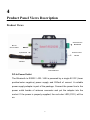
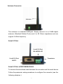
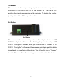
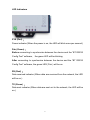
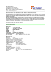
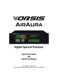
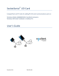
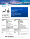
RS-232/422/485 to Bluetooth
Quatech Model SS-BLT-300
Operation Manual
First Edition, May 2008
Table of Contents
1. Introduction ………………………………………………
2. Package checklist ……………………………………………
3. Product Specification ……………………………………
4. Product Panel Views Description ……………………
Product Views
……………………………..…………………
2
3
4
6
6
DC-In Power Outlet
…………………………………………
6
Antenna Connecter
……………………………………………
7
Serial I/O Port of RS-232&RS-422/485
Terminator
Set Button
……………………
……………………………………………………
……………………………………………………
LED Indicators
………………………………………………
7
8
8
9
5. Hardware Installation …………………………………… 10
6. BT RS232 Config Tool Installation & Setup …………11
Tool Installation
………………………………………………
11
Configuration Tool Parameters Configuration ………………
12
Apply “Connect”
………………………………………………
14
Apply “Write”
…………………………………………………
15
Apply “Read”
…………………………………………………
15
Appendix A - Pin Outs and Cable Wiring
DC Power Outlet
…………… 16
…………………………………………
RS-232 Pin Assignment
RS-232 Wiring Diagram
…………………………………
…………………………………
RS-422/485 Pin Assignment
16
16
16
……………………………… 17
RS-422 Wiring Diagram
…………………………………
17
RS-485 Wiring Diagram
…………………………………
17
1
1
Introduction
Thank you for your purchase of the Bluetooth To Serial Adapter. Featuring
Bluetooth wireless technology, it is for replacement of standard RS232 or
industrial RS422/485 cable perfectly, with standard RS232 and industrial
RS422/485 interfaces, so can be easily adopted for industrial machines with
RS232 or RS422/485 interfaces. This adapter is compatible with all Bluetooth
V.2.0-certified and is backward compatible with v1.1/1.2 devices. You can connect
between your computers (Master) and RS232/422/485 devices (Slave) 100
meters away without cables in your working environments.
Security of Bluetooth wireless communication is very strong because it uses the
frequency hopping and 128bit encryption in 2.4Ghz frequency range. Hardware
setting is very easy and simple. The maintenance is very convenience too. One
pair of this adapter will try to connect automatically whenever powered up after
finishing the device’s parameters configured. It does not require extra software for
operation. No installation of driver and application software.
System OS requirements as Win 98/Me/2000/XP/XP x64 / VISTA.
2
2
Package checklist
This product is shipped with the following items:
1 unit of Bluetooth to RS232 / 422 / 485 converter
1 unit of Power Adaptor (9V DC, 200mA)
User Operation Manual
Software CD
NOTE: Notify your sales representative if any of the above items is missing or
damaged
3
3
Product Specification
Serial Port
No. of Ports :
RS-232 / 422 / 485 * 1 Port
●
Port Type : DB9 Female
●
Built-in RS-422/RS-485 Terminal Resister (Surge Protection)
●
Speed : 1200 bps~115.2 K bps
●
Parity : None , Odd , Even
●
Data Bit : 8
●
Stop Bit : 1 , 2
●
Flow Control : DTR / DSR
●
RS-232 Signals : Rx , Tx , GND , RTS , CTS , DTR , DSR , DCD
●
RS-422 Signals : Rx+ , Rx- , Tx+ , Tx- (Full-duplex)
●
RS-485 Signals : Data+ , Data- (Half-duplex)
Bluetooth I/O Port
No. of Ports :Bluetooth * 1 Port
●
Compliant with Bluetooth v2.0+EDR
●
Support Bluetooth Serial port profile(SPP)
●
Operate in 2.4GHz – 2.483GHz ISM Band
●
Support Bluetooth Radio with Class 1 & 2
●
Operating Distance up to 100 Meters
RF
Power : 9V DC / 200mA, Consumption 150mA
Led Lamp :
SYS (red), Pair (green), Rx (red), Tx (green)
Environment : Operating Temperature: 0℃~60℃
Storage Temperature : -25℃~70℃
4
Dimensions : 90 * 65 * 27 mm ( W * D * H )
WEIGHT : 200 gm
Regulatory Approvals :
EMC : FCC Class A, CE Class A
WARRANTY : 1 year
RoHS
5
4
Product Panel Views Description
Product Views
Serial I/O Port
RS422/485
DC-In
Power Outlet
Sync Button
Serial I/O Port
RS-232
Antenna
LED Indicators
DC-In Power Outlet
The Bluetooth to RS232 / 422 / 485 is powered by a single 9V DC (Inner
positive/outer negative) power supply and 200mA of current. A suitable
power supply adapter is part of the package. Connect the power line to the
power outlet beside of antenna connector and put the adapter into the
socket. If the power is properly supplied, the red color LED (SYS ) will be
on.
6
Antenna Connector
Antenna
The antenna is a standard SMA jack. Simply connect it to a 2.0dBi dipole
antenna (Standard Rubber Duck) and it is 50 Ohms impedance and can
support 2.4GHz frequency.
Serial I/O Port
Serial I/O Port
RS-485/RS-422
Serial I/O Port
RS232
Terminator
Serial I/O Port of RS232&RS422/485
To connect the serial data cable between the converter and the serial device.
Follow the parameter setup procedures to configure the converter (see the
following chapters ).
7
Terminator
The purpose is for compensating signal attenuation in long distance
connection at RS-485/RS-422 I/O. If the switch 1 & 2 are set in “ON”
position, the signal compensation will be activated. To disable the function,
just to push switch 1 & 2 to opposite position.
Set Button
Set Button
The purpose is for synchronizing between this adapter device and “BT
RS232 Config Tool” software.
After finishing the parameter setup of “BT
RS232
Config Tool” software, when you click the icon of “Connect” in “BT
RS232
Config Tool” software and then use any point tip to push this button
immediately on the left side of the device. You will see the icon of “Connect”
turn into “Disconnect” and the meaning is successful to active the device.
8
LED Indicators
SYS (Red):
Power indicator (When the power is on, the LED will blink once per second.)
Pair (Green):
Before connecting to synchronize between the device and the “BT RS232
Config Tool” software,
the green LED will be blinking
After connecting to synchronize between the device and the “BT RS232
Config Tool” software, the green LED( Pair ) will be on
RX (Red):
Data received indicator (When data are received from the network, the LED
will be on.)
TX (Green):
Data sent indicator (When data are sent out to the network, the LED will be
on.)
9
5
Hardware Installation
1. Connect this Bluetooth adapter to COM Port of PC and then to connect DC
power adapter and jack into power outlet and DC-in outlet. You will see the
red LED is going to be on and the green LCD will be blink.
2. After running the BT RS232 Config Tool and finish configuration. Click the
icon of “Connect” in tool software and press the set button of this Bluetooth
adapter immediately.
3. The green LED will be turn into on. The Bluetooth adapter is active.
There are two types of RS232 devices in field. One is DTE - Data Terminal
Equipment (such as a PC) and the other one is DCE - Data Communication
Equipment (such as a Modem). You can setup this adapter device as what type of
the RS232 device you are going to connect in DTE or DCE mode to work with it.
At DCE device side meaning is to connect a DTE of this Bluetooth adapter to the
remote DCE of RS232 device (such as a Modem). On the contrary, DTE device
side to connect a DCE of this Bluetooth adapter to any DTE device, such as a
computer device. For example, you can connect a remote modem with a DTE of
this Bluetooth adapter and meanwhile at PC side, you can either connect a DCE
of this Bluetooth adapter to it.
10
6
BT RS232 Config Tool Installation & Setup
When setting up this Bluetooth adapter for the first time, you have to install and
run “BT1.exe” as “BT RS232 config tool” first in your computer device. The utility
CD is enclosed in the device box. Before you use this Bluetooth adapter, you
have to pair it with another unit of this Bluetooth adapter device.
All these Bluetooth to RS-232&RS422/485 adapters must be configured first
before you use it. The purpose of configuration is to pair two units of this Bluetooth
adapter device for an exclusive connection between them, and pairing is done by
utilizing Bluetooth address and PIN code
Tool Installation
When setting up this Bluetooth adapter for the first time, you have to install
the utility software of “BT RS232 config tool” in your computer first which is
an executable program in Windows 32 bit environments.
tool is used to detect and setup the installed.
11
BT RS232 config
BT RS232 Config Tool Parameters Configuration
After double click the icon of BT1 as “BT RS232 Config Tool”, the
configuration screen will be pop-up as the above picture.
A. COM Port
Select COM port number, you have to avoid the port conflict with other
device in computer and use available port number
B. Device Name
Select device name is for identify each one device and you can follow
the name by tool access or retyping the new name by yourself.
C. Local Address
Local address will be automatically changed after finishing the
parameter configuration to apply.
D. Peer Address
Peer address is for pairing device to communicate in a same network
address.
12
E. PIN Code
PIN code is for the purpose of security consideration during as like a
pass key. Device uses this “PIN Code” to identify during connecting
and communication.
F. Role
Role is for identifying a role of the device as a master or slave. The
item of “Role” is chose “Master”. The device will be play like a DTE
mode - Data Terminal Equipment (such as a PC). If the item of “Role”
is chose “Slave” and the device will be play like a DCE - Data
Communication Equipment (such as a Modem)
You can setup this Bluetooth adapter device as what type of the
RS232 device you are going to connect in DTE or DCE mode to work
with it.
G. Discoverable
The item of discoverable is for allowing (or not ) the device is detected
by other Bluetooth devices.
H. Baud Rate
The item of baud rate is for the pack transmission speed. The baud
rate range is from 120 bps~115.2K bps and depend on transmission
distance and environments. Normally, the parameter of baud rate is
sat around 9600 bps.
I.
Handshake(DSR/DTR)
The item of handshake is set at the “Disable” item.
J. Stop Bit
The item of stop bit is set at the “One Bit” item.
K. Parity
13
The item of parity is set at the “None” item.
Apply “Connect”
After finish the parameters configuration, click the icon of “Connect” in
BT RS232 Config Tool screen and meanwhile press the Synchronous
button immediately on the left side of the device. And then the next screen
of parameters configuration is pop-up. The icon of “Connect” is changed to
“Disconnect” and two icons will be turned into active mode on the bottom of
the BT RS232 Config Tool screen.
14
Apply “Write”
To click the item of “Write”, the meaning is to save all parameters after
configuring into the “BT RS232 Config Tool”.
Apply “Read”
To click the item of “Read”, the meaning is to load all parameters as last time
saving from the “BT RS232 Config Tool”. The local address will be updated
the real device address at first time.
15
Appendix A
Pin outs and Connector
□□ DC Power outlet
□□ RS-232 Pin Assignment
The pin assignment scheme for a 9-pin male connector on a DTE is given
below.
PIN 1 : NC
PIN 2 : TXD
PIN 5 : GND
PIN 6 : DTR
PIN 9 : Power ( optional )
PIN 3 : RXD
PIN 7 : CTS
PIN 4 : DSR
PIN 8 : RTS
□□ RS-232 Wiring Diagram
Serial Device
This Bluetooth adapter
2 RX
3 TX
5 GND
4 DTR
6 DSR
3
2
5
6
4
16
TX
RX
GND
DSR
DTR
(Flow Control)
(Flow Control)
□□ RS-422/485 Pin Assignment
The pin assignment scheme for a 4-pin RS-422 is given below.
1
RS-422 : PIN 1 : T+
RS-485 : PIN 1 : D+
2
3
4
PIN 2 : TPIN2 : D-
PIN 3 : R+
PIN 4 : R-
□□ RS-422 Wiring Diagram
Serial Device
T+
TR+
R-
This Bluetooth adapter
3 R+
4 R1 T+
2 T-
□□ RS-485 Wiring Diagram
Serial Device
This Bluetooth adapter
D+
1
D+
D-
2
D-
17