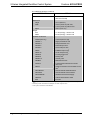
1
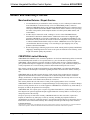
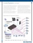
Crestron AV2 & PRO2 2-Series Integrated Dual Bus Control System Operations Guide This document was prepared and written by the Technical Documentation department at: Crestron Electronics, Inc. 15 Volvo Drive Rockleigh, NJ 07647 1-888-CRESTRON All brand names, product names and trademarks are the property of their respective owners. ©2006 Crestron Electronics, Inc. Crestron AV2 & PRO2 2-Series Integrated Dual Bus Control System Contents 2-Series Integrated Dual Bus Control System: AV2 & PRO2 1 Introduction ............................................................................................................................... 1 Features and Functions ................................................................................................ 1 Specifications .............................................................................................................. 3 Physical Description.................................................................................................... 5 Industry Compliance ................................................................................................... 9 Setup ........................................................................................................................................ 10 Network Wiring......................................................................................................... 10 Identity Code ............................................................................................................. 10 Hardware Hookup ..................................................................................................... 10 Programming Software ............................................................................................................ 14 Earliest Version Software Requirements for the PC ................................................. 14 Programming with Crestron SystemBuilder.............................................................. 14 Programming with SIMPL Windows ........................................................................ 14 Example Program ...................................................................................................... 15 Uploading and Upgrading........................................................................................................ 16 Establishing Communication..................................................................................... 16 Programs and Firmware ............................................................................................ 17 Operation ................................................................................................................................. 18 Problem Solving ...................................................................................................................... 23 Possible Problems with the Control System.............................................................. 23 Serial Communication Difficulties with Other Devices Connected to the Control System ....................................................................................................................... 24 Check Network Wiring.............................................................................................. 26 Reference Documents................................................................................................ 27 Further Inquiries ........................................................................................................ 27 Future Updates .......................................................................................................... 27 Software License Agreement................................................................................................... 28 Return and Warranty Policies .................................................................................................. 30 Merchandise Returns / Repair Service ...................................................................... 30 CRESTRON Limited Warranty................................................................................. 30 Operations Guide – DOC. 5957B Contents • i Crestron AV2 & PRO2 2-Series Integrated Dual Bus Control System 2-Series Integrated Dual Bus Control System: AV2 & PRO2 Introduction Features and Functions • • • • • • • • • • • • 2-Series engine with Dual-bus architecture 36 MB of Internal Memory1 4 GB Compact Flash memory card slot Cresnet port – master/slave selectable 10/100 Ethernet capable with SSL encryption Crestron e-Control2 and Crestron RoomView enabled Built-in firewall, NAT and router Six Com ports, eight IR/serial ports, eight Versiport I/O ports, eight relay ports Three Y-Bus2 / One Z-Bus control card expansion slots Internal power supply 2-Space EIA rack-mountable Front panel control with LCD display (PRO2 only) 1. For more information on internal memory, refer to “2-Series Memory & Directory Structure” in the latest version of the Crestron 2-Series Control System Reference Guide (Doc. 6256), which is available from the Crestron website (http://www.crestron.com/manuals). 2. Optional on AV2. 2-Series Engine At the heart of the AV2 & PRO2 is the powerful 32-bit Freescale ColdFire® processor. Crestron's exclusive enhanced real-time operating system makes the AV2 & PRO2 the fastest, most reliable control systems available. Dual Bus Architecture The AV2’s & PRO2's unique dual-bus architecture affords ultra fast communications. The 40 Mbps Y-Bus provides a high-speed backplane for IR, serial and other integrated control ports. Additional control ports and interfaces like MIDI and digital audio processing may be added by installing up to three Y-Bus control Operations Guide – DOC. 5957B 2-Series Integrated Dual Bus Control System: AV2 & PRO2 • 1 2-Series Integrated Dual Bus Control System Crestron AV2 & PRO2 cards (expansion cage option required for AV2). At a blazing 300 Mbps, the Z-Bus supports Fast Ethernet with future support for other emerging technologies. Cresnet® Cresnet is the communications backbone for many Crestron touchpanels, keypads, lighting controls and other devices. The Cresnet bus is a simple, yet flexible 4-wire network that provides rock-solid bidirectional communication and power for up to 252 Cresnet devices. Cresnet Slave Mode Selectable Cresnet Slave Mode enables the AV2 & PRO2 to be configured as Cresnet slave devices, effectively transforming them into Cresnet expansion modules. Such flexibility can offer a cost-effective solution for system expansion, providing a host of additional control ports in a single module. Ethernet Crestron pioneered the IP-based control system to harness the vast possibilities of Ethernet and the Internet for remote control, monitoring, programming and diagnostics. The AV2 & PRO2 are designed to deliver the world's most advanced IP control solutions. A choice of single or dual port Ethernet cards enables a full-duplex 10/100 Ethernet connection with built-in Web server and email client and support for both static and dynamic IP addressing. Crestron e-Control®2 Crestron's award-winning e-Control 2 XPanel solutions offer the most flexible range of IP control possibilities available. Using a Windows® computer or CE/PocketPC™ PDA device, e-Control 2 provides an amazing control GUI that looks and behaves just like a Crestron Isys® touchpanel. Crestron RoomView® Every Ethernet-enabled 2-Series control system works directly with Crestron's exclusive RoomView Help Desk software for the industry's most comprehensive facility-wide asset management solution. SSL All Ethernet-enabled 2-Series control systems support SSL (Secure Sockets Layer), the industry standard for protecting sensitive network communications. NAT The AV2’s & PRO2's onboard NAT (Network Address Translator) acts as a firewall and router to facilitate the configuration of a private control LAN with a single-point connection to the client's LAN (Dual-port Ethernet card required). Memory Expansion A memory card slot accessible on the rear panel allows for easy expansion of the AV2’s & PRO2's internal memory using any Type II Compact Flash memory card up to 4 GB. Note that compact flash memory supports FAT file structure. 2 • 2-Series Integrated Dual Bus Control System: AV2 & PRO2 Operations Guide – DOC. 5957B Crestron AV2 & PRO2 2-Series Integrated Dual Bus Control System Front Panel Control (PRO2 only) The PRO2 includes a programmable front control panel with LCD display and control port status indicators. The PRO2's front panel serves as a ready user interface for system configuration and diagnostics and can also be custom programmed to enable menu-driven control capability. Specifications Specifications for the AV2 & PRO2 are listed in the following table. AV2 & PRO2 Specifications SPECIFICATION DETAILS Processor CPU 32-bit Freescale Coldfire Microprocessor Processing Speed 257 MIPS (Dhrystone 2.1 benchmark) Memory SDRAM 32 MB NVRAM 256 kB Flash 4 MB Compact Flash expandable up to 4 GB (not included) Operating System Real-time preemptive multithreaded/multitasking kernel; FAT32 file system with long names; supports SIMPL Windows and SIMPL+ Ethernet With C2ENET-1 10/100BaseT, auto-negotiating, full/half duplex, static IP or DHCP/DNS, SSL, TCP/IP, UDP/IP, CIP, SMTP, built-in Web server and e-mail client; supports Crestron e-Control2 Xpanel and RoomView applications With C2ENET-2 All above features plus: built-in firewall, router and network address translator (NAT) Expansion Slots Y-Bus1 (3) (AV2 requires CAGE2 accessory, sold separately); Accept all Y-Bus control cards Z-Bus2 (1) Accepts all Z-Bus control cards Power Requirements Internal Universal Power Supply 2.3 Amps, 100-250 Volts AC, 50/60 Hz Available Cresnet Power 50 Watts (shared with control card expansion slots) Network Power Fuse Rating 4A, 250V (1 ¼” x ¼” Slow Blow Fuse Series) 50 watts (DC) available for Cresnet devices Environmental Temperature 41º to 113ºF (5º to 45ºC) Humidity 10% to 90% RH (non-condensing) (Continued on following page) Operations Guide – DOC. 5957B 2-Series Integrated Dual Bus Control System: AV2 & PRO2 • 3 2-Series Integrated Dual Bus Control System Crestron AV2 & PRO2 AV2 & PRO2 Specifications (Continued) SPECIFICATION Enclosure DETAILS Black metal, 2U 19” rack-mountable (rack ears included) Dimensions Height 3.47 in (8.82 cm) Width 19.00 in (48.26 cm) with ears; 17.03 in (43.25 cm) without ears Depth 9.69 in (24.61 cm) Weight AV2 7.1 lbs (3.22 kg) – with line cord PRO2 8.0 lbs (3.63 kg) – with line cord Available Accessories CAGE2 (AV2 only) 3-Card expansion cage C2ENET-1 Single port Ethernet card C2ENET-2 Dual port Ethernet card C2COM-2 Dual COM port card3 C2COM-3 Three COM port card3 C2IR-8 8 IR/Serial output card3 CNXIO-16 16 I/O Versiport card3 CNXAO-8 8 Analog output card3 CNXRY-8 8 Relay card3 CNXRY-16 16 Relay card3 CNXMIDI MIDI Interface card3 C2VEQ-4 4-Channel Volume/EQ and 4x4 matrix mixer card3 CNXTA Telephone interface and Voice/WAV sound card3 C2N-HBLOCK Cresnet Network Distribution Block C2N-NPA8 Cresnet Network Poll Accelerator C2N-SPWS300 300 Watt Cresnet Power Supply CNSP-XX Custom Serial Interface Cable IRP2 IR Probe 1. 40 Mb/s parallel communications; Internal backplane for integrated control ports and Y-Bus expansion slots. 2. 300 Mb/s parallel communications; Backplane for Z-Bus expansion slots. 3. AV2 requires CAGE2 for card installation. 4 • 2-Series Integrated Dual Bus Control System: AV2 & PRO2 Operations Guide – DOC. 5957B Crestron AV2 & PRO2 2-Series Integrated Dual Bus Control System Physical Description This section provides information on the connections, controls and indicators available on your AV2 & PRO2. AV2 Physical View (shown with accessory cards installed in CAGE2; optional) PRO2 Physical View (shown with accessory cards installed) Operations Guide – DOC. 5957B 2-Series Integrated Dual Bus Control System: AV2 & PRO2 • 5 2-Series Integrated Dual Bus Control System Crestron AV2 & PRO2 AV2 & PRO2 Overall Dimensions 1 2 3 8 4 5 9 10 6 7 11 12 9.69 in (24.61 cm) 17.03 in (43.25 cm) 1 13 3.47 in (8.82 cm) 14 15 16 6 • 2-Series Integrated Dual Bus Control System: AV2 & PRO2 17 18 19 Operations Guide – DOC. 5957B Crestron AV2 & PRO2 2-Series Integrated Dual Bus Control System Connectors, Controls & Indicators # CONNECTORS1, CONTROLS & INDICATORS 1 COMPUTER FRONT PANEL DESCRIPTION DB9F connectors (one on front panel and one on rear) are used when programming with a PC. Each port is modem compatible. (Modem and PC cables not included.) REAR PANEL 2 PWR LED Indicates 24 Volts DC power supplied from Cresnet control network. 3 NET LED Indicates communication with Cresnet System. 2 Illuminates when a message is detected. To decipher content, examine the message available from the menu function buttons or through the Crestron Toolbox™. 4 MSG LED 5 COM (A – F) LEDS3 6 IR – SERIAL (A – H) LEDS3 RXD - Illuminate during reception of data from serial devices attached to the respective COM ports. TXD – Illuminate during transmission of data to serial devices attached to the respective COM ports. RTS – Illuminate to reflect state of the RTS pin on the respective COM port. If no handshaking is specified, the RTS line will be high and the associated LED is also high. When RTS flow control is enabled, RTS indicates the unit is ready to receive data from serial devices attached to the respective COM ports. CTS – Illuminate to reflect state of the CTS pin on the respective COM port. An illuminated LED means the CTS line is high. When CTS flow control is enabled, CTS indicates the serial devices on the respective COM ports are ready to accept data. 3 Indicate activity on the respective IR-SERIAL lines. 7 RELAY (1 – 8) LEDS 8 RESET BUTTONS HW-R - Initiates system hardware reset. SR-R - Pressing this in combination with HW-R button performs a system restart without loading the program. Pressing it alone momentarily while the system is running restarts the program. Indicate the respective relay is closed. 9 LAN (A – B) LEDS4 LNK – Indicate the Ethernet card has established a valid Ethernet connection. ACT – Indicate communication (activity) at the respective port on the Ethernet card. 10 LCD SCREEN & MENU BUTTONS3 11 INPUT – OUTPUT (1 – 8) LEDS3 Indicate when input voltage thresholds for the respective I/O ports are exceeded or when the output is active. 12 SLOT (1 – 3) LEDS3 Indicate an expansion card is inserted into the respective slot. These LEDS turn off momentarily when data is sent to the card or received from the card. 13 NET Permits local control; refer to “Operation” on page 18 for details. Four-position terminal block connector for data and power. Connects to Cresnet control network. Pin 1 (24) Power Pin 2 (Y) Data Pin 3 (Z) Data Pin 4 (G) Ground (Continued on following page) Operations Guide – DOC. 5957B 2-Series Integrated Dual Bus Control System: AV2 & PRO2 • 7 2-Series Integrated Dual Bus Control System Crestron AV2 & PRO2 Connectors, Controls & Indicators (Continued) # 14 CONNECTORS1, CONTROLS & INDICATORS COM (A – F)5, 6, 7 COM A COM F DESCRIPTION (6) DB9 male, bidirectional RS-232/422/485 ports. Up to 115.2k baud, hardware and software handshaking support. Ports C-F support C2N-NPA8 Network Poll Accelerator8. PIN DIRECTION To AV2 or PRO2 (RXD-) RS-422 Receive Data (Idles low) 2 To AV2 or PRO2 (RXD) RS-232 Received Data 3 From AV2 or PRO2 (TXD) RS-232 Transmitted Data 4 From AV2 or PRO2 (TXD+) RS-422 Transmit Data (Idles high) 5 * 15 INFRARED - SERIAL OUTPUT (A – H)9 A B C D S GSGSGSG E F G H SGS GSGS G DESCRIPTION 1* RS-232 and RS-422 Signal Common 6 To AV2 or PRO2 (RXD+) RS-422 Receive Data (Idles high) 7 From AV2 or PRO2 (RTS) RS-232 Request to Send 8 To AV2 or PRO2 (CTS) RS-232 Clear to Send 9 From AV2 or PRO2 (TXD-) RS-422 Transmit Data (Idles low) RS-422 transmit and receive are balanced signals requiring two lines plus a ground in each direction. RXD+ and TXD+ should idle high (going low at start of data transmission). RXD- and TXD- should idle low (going high at start of data transmission). If necessary, RXD+/RXD- and TXD+/TXD- may be swapped to maintain correct signal levels. (8) 2-pin 3.5 mm detachable terminal blocks IR/Serial output ports. IR output up to 1.2 MHz; 1-way serial TTL/RS-232 (0-5 Volts) up to 115.2k baud. Individual signal generator per port, allowing simultaneous firing of all ports. INFRARED - SERIAL OUTPUT I/O (1 – 8)10 16 (1) 9-pin 3.5 mm detachable terminal block comprising (8) digital input/output or analog input ports (referenced to GND); Digital Input: Rated for 0-24 Volts DC, input impedance 20k ohms, logic threshold 1.24 Volts DC; Digital Output; 250 mA sync from maximum 24 Volts DC, catch diodes for use with “real world” loads; Analog Input: Rated for 0-10 Volts DC, protected to 24 Volts DC maximum, input impedance 20k ohms; Programmable 5 Volts, 2k ohms pull-up resistor per pin. 1 2 3 4 5 6 7 8G S6 I/O RELAY OUTPUT (1 – 8) 17 1 2 3 4 5 6 7 8 (2) 8-pin 3.5 mm detachable terminal blocks comprising (8) normally open, isolated relays; Rated 1 Amp, 30 Volts AC/DC, MOV arc suppression across contacts. S7 RELAY OUTPUT 1. 2. 3. 4. 18 100 – 240V ~2.4A 50/60 Hz (POWER SUPPLY) 19 CHASSIS GROUND (1) IEC Socket, mates with removable power cord (included). (1) 6-32 screw, chassis ground lug. Interface connectors for NET, Infrared-Serial, I/O and Relay Output ports are provided with the unit. This LED was labeled “ERR” on units manufactured prior to 2005. It is functionally the same; only the labeling has changed. PRO2 only. LAN LEDs are active only if a single port or dual port Ethernet card (which is field installed) occupies the Z-Bus slot. 8 • 2-Series Integrated Dual Bus Control System: AV2 & PRO2 Operations Guide – DOC. 5957B Crestron AV2 & PRO2 2-Series Integrated Dual Bus Control System 5. The pinout of each 9-pin port is non-standard; it contains RS-422 pins in addition to RS-232. This may result in a conflict with some equipment and therefore all nine pins should not be used. Only the required pins for each communication type should be connected. For RS-232 and –422, pins 2, 3, 5, 7 and 8 are wired straight through. 6. Data Set Ready (DSR) and Data Terminal Ready (DTR) are not supported. 7. To support RS-485, tie pin 1 (RXD-) to pin 9 (TXD-) COM (DB9) CONNECTOR RS-485 BUS and pin 4 (TXD+) to pin 6 (RXD+) in the cable. (Refer to table at right.) Tie Pins 1 & 9 Tie Pins 4 & 6 + Pin 5 G 8. The Cresnet Poll Accelerator effectively increases the network speed, fan-out and device addresses by a factor of 8 for each Poll Accelerator added to the system. 9. Transmission levels on the infrared – serial output connectors are in the 0 to +5 VDC range, which may not be compatible with all RS-232 devices. 10. Digital outputs are TTL values and may not work with devices requiring a “dry” contact closure (e.g. low voltage motor controllers). Industry Compliance These products are Listed to applicable UL Standards and requirements by Underwriters Laboratories Inc. (E174344) As of the date of manufacture, the AV2 & PRO2 have been tested and found to comply with specifications for CE marking and standards per EMC and Radiocommunications Compliance Labelling. NOTE: This device complies with part 15 of the FCC rules. Operation is subject to the following two conditions: (1) this device may not cause harmful interference, and (2) this device must accept any interference received, including interference that may cause undesired operation. This equipment has been tested and found to comply with the limits for a Class B digital device, pursuant to part 15 of the FCC Rules. These limits are designed to provide reasonable protection against harmful interference in a residential installation. This equipment generates, uses and can radiate radio frequency energy and if not installed and used in accordance with the instructions, may cause harmful interference to radio communications. However, there is no guarantee that interference will not occur in a particular installation. If this equipment does cause harmful interference to radio or television reception, which can be determined by turning the equipment off and on, the user is encouraged to try to correct the interference by one or more of the following measures: Reorient or relocate the receiving antenna. Increase the separation between the equipment and receiver. Connect the equipment into an outlet on a circuit different from that to which the receiver is connected. Consult the dealer or an experienced radio/TV technician for help. Operations Guide – DOC. 5957B 2-Series Integrated Dual Bus Control System: AV2 & PRO2 • 9 2-Series Integrated Dual Bus Control System Crestron AV2 & PRO2 Setup Network Wiring When wiring the network, consider the following: • Use Crestron Certified Wire. • Use Crestron power supplies for Crestron equipment. • Provide sufficient power to the system. CAUTION: Insufficient power can lead to unpredictable results or damage to the equipment. Please use the Crestron Power Calculator to help calculate how much power is needed for the system (http://www.crestron.com/calculators). • For larger networks, use a Cresnet Hub/Repeater (CNXHUB) to maintain signal quality For more details, refer to “Check Network Wiring” on page 26. Identity Code Net ID The Net IDs of the AV2 & PRO2 have been factory set to 02. This Net ID is defined as the “Master” control system. The Net IDs of multiple AV2 & PRO2 devices in the same system must be unique; this means there will be a master/slave relationship between units (only the Net ID of the master will be left at 02). Net IDs are changed from a personal computer (PC) via the Crestron Toolbox™. When setting the Net ID, consider the following: • The Net ID of each unit must match an ID code specified in the SIMPL Windows program. • Each network device must have a unique Net ID. For more details, refer to the Crestron Toolbox help file. IP ID The IP ID is set within the AV2’s or PRO2’s table using Crestron Toolbox. For information on setting an IP table, refer to the Crestron Toolbox help file. The IP IDs of multiple AV2 & PRO2 devices in the same system must be unique. When setting the IP ID, consider the following: • The IP ID of each unit must match an IP ID specified in the SIMPL Windows program. • Each device using IP to communicate with a control system must have a unique IP ID. Hardware Hookup Ventilation The AV2 & PRO2 should be used in a well-ventilated area. The venting holes should not be obstructed under any circumstances. If the AV2 or PRO2 is hot to the touch, consider using forced air ventilation and/or incrementing the spacing between units. To prevent overheating, do not operate this product in an area that exceeds the environmental temperature range listed in the table of specifications. Consideration must be given if installed in a closed or multi-unit rack assembly since the operating 10 • 2-Series Integrated Dual Bus Control System: AV2 & PRO2 Operations Guide – DOC. 5957B Crestron AV2 & PRO2 2-Series Integrated Dual Bus Control System ambient temperature of the rack environment may be greater than the room ambient temperature. Contact with thermal insulating materials should be avoided on all sides of the unit. Rack Mounting The AV2 & PRO2 can be mounted in a rack or stacked with other equipment. Two “ears” are provided with the AV2 & PRO2 so that the units can be rack mounted. These ears must be installed prior to mounting. Complete the following procedure to attach the ears to the unit. The only tool required is a #2 Phillips screwdriver. WARNING: To prevent bodily injury when mounting or servicing this unit in a rack, take special precautions to ensure that the system remains stable. The following guidelines are provided to ensure your safety: • When mounting this unit in a partially filled rack, load the rack from the bottom to the top with the heaviest component at the bottom of the rack. • If the rack is provided with stabilizing devices, install the stabilizers before mounting or servicing the unit in the rack. NOTE: If rack mounting is not required, rubber feet are provided for tabletop mounting or stacking. Apply the feet near the corner edges on the underside of the unit. NOTE: Reliable earthing of rack-mounted equipment should be maintained. Particular attention should be given to supply connections other than direct connections to the branch circuit. (e.g., use of power strips). To install the ears: 1. There are screws that secure each side of the AV2 & PRO2 top cover. Using a #2 Phillips screwdriver, remove the three screws closest to the front panel from one side of the unit. Refer to the diagram following step 3 for a detailed view. 2. Position a rack ear so that its mounting holes align with the holes vacated by the screws in step 1. 3. Secure the ear to the unit with three screws from step 1, as shown in the following diagram. Ear Attachment for Rack Mounting (this image shows a 1RU device) USE COVER SCREWS 4. Bussing Strip Installation Operations Guide – DOC. 5957B Repeat procedure (steps 1 through 3) to attach the remaining ear to the opposite side. The 2-Series integrated dual bus control system is supplied with two brass bussing strips to facilitate commoning (linking) of multiple terminal block connections. The 2-Series Integrated Dual Bus Control System: AV2 & PRO2 • 11 2-Series Integrated Dual Bus Control System Crestron AV2 & PRO2 bussing strips are constructed with four terminal block positions and may be trimmed to size for various applications or different devices. One strip is supplied for each 8-position terminal block. Memory Card Installation Memory Card Removal 1. To utilize the bussing strip, determine the number of relays to be commoned for the equipment being installed. If less than four, the strip can be trimmed to size with a pair of scissors or wire snips. 2. Loosen the terminal block screws and insert the first leg of the bussing strip into the first common position of the terminal block. The strip engages the other common positions automatically. 3. Remove approximately 1/8” of the jacket from the common wire and insert the conductor into one of the terminal block common positions. Tighten the terminal block screws to lock the wire and bussing strip into place. Insulate the strip by folding a piece of ¾” wide vinyl electrical tape (such as Scotch 33+) over the spine and as much of the individual legs as possible. Excess tape at each end of the strip should be pressed closed, then trimmed to within approximately 1/16” of the end of the strip. 4. When wiring the remaining conductors, remove approximately 1/8” of the jacket and insert the wires into the proper terminal block positions. To prevent the possibility of electrical shorts, it is essential that these conductors do not touch any uninsulated portion of the bussing strip. 5. Securing a tie wrap around the bussing strip is a useful way to provide strain relief for the wires connected to the terminal block. The onboard 36 MB memory of the 2-Series integrated dual bus control system is enhanced with a 4 GB expansion slot that supports off-the-shelf Type II compact flash memory and “microdrive” devices. The slot is accessible on the rear panel of the unit. Complete the following procedures to install the memory card. Power does not have to be disconnected to insert memory. Note that compact flash memory supports FAT file structure. 1. Loosen the screw that secures the memory slot cover located to the left of the COMPUTER port on the rear panel. 2. Pull on the screw to remove the screw and cover. 3. Observe handling precautions of the memory card manufacturer and insert card into the open slot. 4. Align and reposition cover over slot and tighten the screw. Complete the following procedures to remove the memory card. Power does not have to be disconnected to remove memory. 1. Loosen the screw that secures the memory slot cover located to the left of the COMPUTER port on the rear panel. 2. Pull on the screw to remove the screw and cover. 3. Press the eject button located on the extreme right of the slot. 4. Observe handling precautions of the memory card manufacturer and remove card from the slot. 5. Align and reposition cover over slot and tighten the screw. 12 • 2-Series Integrated Dual Bus Control System: AV2 & PRO2 Operations Guide – DOC. 5957B Crestron AV2 & PRO2 Connect the Device 2-Series Integrated Dual Bus Control System Make the necessary connections as called out in the illustration that follows this paragraph. Refer to “Network Wiring” on page 10 before attaching the 4-position terminal block connector. Apply power after all connections have been made. When making connections to the AV2 & PRO2, consider the following: • Use Crestron power supplies for Crestron equipment. • The included cable cannot be extended. Hardware Connections for the AV2 & PRO2 COMPUTER: TO SERIAL PORT ON PC (ANOTHER DB9 CONNECTOR ON FRONT PANEL) CRESNET: TO ANY CRESNET NETWORK DEVICE COM (A - F): TO ANY RS-232, -422 OR -485 DEVICE GROUND INFRAREDSERIAL OUTPUT (A - H): TO IRP2 OR SERIAL DEVICES RELAY OUTPUT (1 - 8): TO CONTROLLABLE DEVICES I/O (1 - 8): TO CONTROLLABLE DEVICES FROM DEVICE OUTPUTS - CONTACT CLOSURES - RELAY CLOSURES Operations Guide – DOC. 5957B 100 - 240V ~2.4A 50/60 Hz (POWER SUPPLY): TO OUTLET (POWER CORD SUPPLIED) 2-Series Integrated Dual Bus Control System: AV2 & PRO2 • 13 2-Series Integrated Dual Bus Control System Crestron AV2 & PRO2 Programming Software Have a question or comment about Crestron software? Answers to frequently asked questions (FAQs) can be viewed in the Online Help section of the Crestron website. To post a question or view questions you have submitted to Crestron’s True Blue Support, log in at http://support.crestron.com. First-time users will need to establish a user account. Earliest Version Software Requirements for the PC NOTE: Crestron recommends that you use the latest software to take advantage of the most recently released features. The latest software is available from the Crestron website. Crestron has developed an assortment of Windows-based software tools to develop a Cresnet system. The following are the minimum recommended software versions for the PC: Software TASK REQUIRED SOFTWARE VERSION Program control system to operate AV2 & PRO2. SIMPL Windows version 2.02.08 or later with SIMPL+ Cross Compiler version 1.1 or later and Library update 145 or later; Also requires Crestron Database version 15.6.2 or later. Upload program and firmware. Crestron Toolbox 1.01.06 or later. Program with simple wizards (optional but recommended). Crestron SystemBuilder™ version 2.0.6 or later. Refer to software release notes or Crestron website for other required Crestron software packages. Programming with Crestron SystemBuilder Crestron SystemBuilder is the easiest method of programming, but does not offer as much flexibility as SIMPL Windows. For additional details, download SystemBuilder from the Crestron website and examine the extensive help file. Programming with SIMPL Windows NOTE: While SIMPL Windows can be used to program the AV2 & PRO2, it is recommended to use SystemBuilder for configuring a system. SIMPL Windows is Crestron’s premier software for programming Crestron control systems. It is organized into two separate, but equally important “Managers”. Configuration Manager Configuration Manager is the view where programmers “build” a Crestron control system by selecting hardware from the Device Library. 14 • 2-Series Integrated Dual Bus Control System: AV2 & PRO2 Operations Guide – DOC. 5957B Crestron AV2 & PRO2 2-Series Integrated Dual Bus Control System • To incorporate the AV2 or PRO2 into the system, drag the AV2 or PRO2 from the Control Systems folder of the Device Library and drop it in the System Views. Locating the AV2 & PRO2 in the Device Library Programming Manager Programming Manager is the view where programmers “program” a Crestron control system by assigning signals to symbols. The symbol can be viewed by double clicking on the icon or dragging it into Detail View. A description for each signal in the symbol is described in the SIMPL Windows help file (F1). Example Program An example program for the AV2 & PRO2 is available from the Crestron website (http://www.crestron.com/exampleprograms). Operations Guide – DOC. 5957B 2-Series Integrated Dual Bus Control System: AV2 & PRO2 • 15 2-Series Integrated Dual Bus Control System Crestron AV2 & PRO2 Uploading and Upgrading Crestron recommends using the latest programming software and that each device contains the latest firmware to take advantage of the most recently released features. However, before attempting to upload or upgrade, it is necessary to establish communication. While the next section provides an overview for communication, refer to “Establishing Communications with the Control System” in the Crestron 2-Series Control System Reference Guide (Doc. 6256) for serial and TCP/IP connection details. If communications cannot be established, refer to “Troubleshooting Communications” in the same guide. Establishing Communication Use Crestron Toolbox for communicating with the AV2 & PRO2; refer to the Crestron Toolbox help file for details. There are two methods of communication. Direct Serial Communication NOTE: Required for initial setup of Ethernet parameters. Direct Serial Communication PC RUNNING CRESTRON TOOLBOX TCP/IP Communication SERIAL VIA CRESTRON CABLE STCP-502PC OR EQUIVALENT AV2 or PRO2 • The COMPUTER port on the AV2 & PRO2 connects to the serial port on the PC via a serial cable (Crestron STCP-502PC or equivalent). • Use the Address Book in Crestron Toolbox to create an entry using the expected serial communication protocol (RS232, auto-detect baud rate, no parity, 8 data bits, 1 stop bit, XON/XOFF disabled, RTS/CTS enabled). • icon); Display the AV2’s or PRO2’s “System Info” window (click the communications are confirmed when the device information is displayed. Ethernet Communication PC RUNNING CRESTRON TOOLBOX ETHERNET AV2 or PRO2 • Establish direct serial communication between AV2 or PRO2 and PC. • Enter the IP address, IP mask, and default router of the AV2 or PRO2 via the Crestron Toolbox (Functions | Ethernet Addressing); otherwise enable DHCP. • Confirm Ethernet connections between AV2 or PRO2 and PC. If connecting through a hub or router, use CAT5 straight through cables with 8-pin RJ-45 connectors. Alternatively, use a CAT5 crossover cable to connect the two LAN ports directly, without using a hub or router. 16 • 2-Series Integrated Dual Bus Control System: AV2 & PRO2 Operations Guide – DOC. 5957B Crestron AV2 & PRO2 2-Series Integrated Dual Bus Control System • Use the Address Book in the Crestron Toolbox to create an entry for the AV2 or PRO2 with the AV2’s or PRO2’s TCP/IP communication parameters. • Display the “System Info” window (click the or PRO2 entry. • Use the Crestron Toolbox to create the AV2 or PRO2 IP table. icon) and select the AV2 ⇒ Select Functions | IP Table Setup. ⇒ Either add, modify, or delete entries in the IP table. The AV2 or PRO2 can have only one IP table entry. ⇒ A defined IP table can be saved to a file or sent to the device. • When using the AV2 or PRO2 as a “slave”, edit the “master” control system’s IP table to include an entry for the slave AV2 or PRO2. The entry should list the AV2 or PRO2’s IP ID (specified on the AV2’s or PRO2’s IP table) and the internal gateway IP address 127.0.0.1. Programs and Firmware • Display the network device tree (Tools | Network Device Tree) to show all network devices connected to the control system. Right-click on the AV2 or PRO2 to display actions that can be performed on the AV2 or PRO2: ⇒ Upgrade firmware ⇒ Change Net ID • Upload the SIMPL Windows file to the control system using SIMPL Windows or Crestron Toolbox. • Upgrade AV2 & PRO2 firmware via Crestron Toolbox. ⇒ Establish serial or TCP/IP communications with the AV2 or PRO2 and display the “System Info” window. ⇒ Select Functions | Firmware… to upgrade the AV2 or PRO2 firmware. For details on uploading and upgrading, refer to the SIMPL Windows help file or the Crestron Toolbox help file. Operations Guide – DOC. 5957B 2-Series Integrated Dual Bus Control System: AV2 & PRO2 • 17 2-Series Integrated Dual Bus Control System Crestron AV2 & PRO2 Operation Crestron 2-Series Control Systems are the brain of a complete integrated audio/visual or automation solution, serving as the central processor and I/O interface. Every audio, video and environmental element of the home, boardroom, classroom or command center becomes integrated and accessible through the control system. No matter how complex or basic, Crestron control systems are entirely customprogrammable to attain the exact functionality required. The AV2 is an economical version of the PRO2, providing all the features and performance of the PRO2 without the front panel LCD display and pushbuttons. The AV2 is perfect for medium to large-scale commercial and residential control applications. The flagship PRO2 is designed for demanding medium to large-scale commercial and residential control applications. The PRO2 includes a programmable front panel with LCD display, four menu selection buttons, six user buttons and port status LEDs. The PRO2’s front panel serves as a ready user interface for system configuration and diagnostics and can also be custom programmed to enable menudriven end-user control capability. The front panel may be password-protected. The front panel of the PRO2 incorporates a reverse mode (yellow on black) LCD screen shown below. The screen contains two lines with up to 40 characters per line; it is used to extend features and gain access to the system including the SIMPL program. To the right of the display are four menu selection buttons. These buttons permit the user to navigate through the menus and also to control the brightness of the display backlight. Below the display are six menu function buttons. These buttons offer extended features of the PRO2. For details, refer to the help file in the “Front Panel Editor” utility of SIMPL Windows. Main Menu (Default LCD Display) LCD Screen with Menu Selection and Menu Function Buttons Menu Selection Buttons MENU This menu selection button functions as a return and will eventually bring the screen display to the menu default state (Main Menu). These buttons scroll the listed information UP and DOWN. BKLT This button adjusts the brightness of the LCD backlight and the front panel LEDs. 18 • 2-Series Integrated Dual Bus Control System: AV2 & PRO2 Operations Guide – DOC. 5957B Crestron AV2 & PRO2 Menu Function Buttons 2-Series Integrated Dual Bus Control System PANEL NOTE: If the unit does not have a loaded program with front panel screens defined, the PANEL menu function does not appear on the Main Menu. This menu function button displays a programmable interface offering command text, indirect text and hierarchical screen structure. For details, refer to the help file in the “Front Panel Editor” utility of SIMPL Windows. INFO This button displays the default Info Menu, shown after this paragraph. System information including the loaded SIMPL program version (Rems), hardware specs such as types of expansion cards installed in the card slots (HWare), the Cresnet devices detected (Net), the Ops version (Ops) and the communication settings (Com) is displayed. NOTE: The information within each of the commands displayed in the Info Menu may exceed the 40 characters permitted per line. If this occurs, use the two rightmost menu function buttons to scroll left and right. Refer to the two arrows shown beneath the Info Menu illustrated after this note for location and identification. Default Info Menu MSG This button displays a list (error log) of the most recent errors. Error messages may be the result of hardware or software failure, hardware incompatibility with software definitions or a programming error. The following table lists and defines the four types of error messages that may appear: Error Message Types TYPE DEFINITION Notice An event has occurred that is noteworthy, but will not affect program operation. Warning An event has occurred that could affect program operation but the program can still run normally. Error An event has occurred that indicates that the program is not operating as expected. Fatal An event has occurred that will prevent the program from running. The top line of the LCD screen provides a single error message from the error log. In the sample shown below, the message indicates that the system expects a card to be inserted into slot 1. The bottom line of the LCD screen provides commands. The user can use NEXT or PREV to scroll through the entire error log. Some messages may Operations Guide – DOC. 5957B 2-Series Integrated Dual Bus Control System: AV2 & PRO2 • 19 2-Series Integrated Dual Bus Control System Crestron AV2 & PRO2 be too long to be displayed across the top line of the LCD screen; use << and >> to scroll left and right respectively or examine them through Crestron Toolbox. Users may wish to periodically save the error log to a file. This can be an invaluable aid in troubleshooting problems with the control system. Refer to the Crestron Toolbox help file for details. The CLEAR button can to used to empty the error log and extinguish the MSG front panel LED. A security message prompts the user to confirm the command. NOTE: The up and down menu selection buttons to the right of the LCD screen may be used in lieu of the NEXT and PREV menu function buttons. MSG Submenu with Sample Message TIME This menu can only be obtained by entering the correct access code. The default access code is 1234. To assign a unique access code, use the following procedures: 1. Establish communication with the control system (refer to “Establishing Communication” on page 16). 2. Launch the Crestron Toolbox and display the “System Info” window by selecting Tools | System Info (or by clicking the 3. icon). Select Functions | Display Message to bring up the “Display Message” window. “Display Message” Window 4. Click the “Password” button to open the “Front Panel Password” window. 20 • 2-Series Integrated Dual Bus Control System: AV2 & PRO2 Operations Guide – DOC. 5957B Crestron AV2 & PRO2 2-Series Integrated Dual Bus Control System “Front Panel Password” Window NOTE: “Front Panel Password” window from Crestron Toolbox version 1.02.29 or later. 5. To change the current password, use the drop down lists to select the four numbers for the new password, then click the Change button. NOTE: New password must be four numbers (each in the range of 1-6). The default Date/Time Menu, shown after this paragraph, permits alterations to the current system date and time shown on the top line. Select either Date or Time to open the respective submenu. Default Date/Time Menu The Date Set submenu, shown after this paragraph, permits alterations to the current system date shown on the top line. Use the Dn (down) and Up selection buttons for month, day and year decremental or incremental changes, respectively. Date Set Submenu The Time Set submenu, shown after this paragraph, permits alterations to the current system time, shown on the top line. Use the Dn (down) and Up selection buttons for hour and minute (Min) decremental or incremental changes, respectively. The AM/PM selection button toggles between AM and PM. Operations Guide – DOC. 5957B 2-Series Integrated Dual Bus Control System: AV2 & PRO2 • 21 2-Series Integrated Dual Bus Control System Crestron AV2 & PRO2 Time Set Submenu COM This button allows the user to monitor the transmission and reception traffic on every COM-type device and card that is active in the SIMPL Windows program that is loaded into the 2-Series control system. This includes all devices connected via Cresnet (e.g. ST-COM) and Ethernet (e.g. MC2E or QM-RMC) as well as the builtin card (slot 4) and cards inserted into the expansion slots (e.g. C2COM-2 or C2COM-3). Serial transmission to IR ports can also be monitored. Refer to “Serial Communication Difficulties with Other Devices Connected to the Control System” on page 24 for details. NOTE: Only COM-type devices and cards in the SIMPL Windows program that are active (not commented out) are monitored. 22 • 2-Series Integrated Dual Bus Control System: AV2 & PRO2 Operations Guide – DOC. 5957B Crestron AV2 & PRO2 2-Series Integrated Dual Bus Control System Problem Solving Problems may occur with the 2-Series integrated dual bus control system itself or there may be serial communication difficulties with other devices connected to the control system. The next two sections address possible problem solving tools or procedures for each. Possible Problems with the Control System The following table provides corrective action for possible trouble situations. If further assistance is required, please contact a Crestron customer service representative. AV2 & PRO2 Troubleshooting TROUBLE POSSIBLE CAUSE(S) CORRECTIVE ACTION Unexpected response from control system. Network devices are not communicating with the control system. Use Crestron Toolbox to poll the network. Verify network connection to the device. PWR LED does not illuminate. Control system is not receiving power. Use the provided Crestron power source. Verify connections. MSG LED illuminates. Hardware or software failure, hardware incompatibility with software definitions or programming error. Verify that hardware configuration matches software configuration (i.e. card is in proper slot as defined by program). If using PRO2, depress MSG button on front panel for specific error. Use Crestron Toolbox to display the error log. Refer to “Error Message Definitions” in the latest version of the Crestron 2-Series Control System Reference Guide (Doc. 6256) for more details. Compilation error RLCMCVT166 & RLCMCVT177. Poor analog versus serial signal definition in the SIMPL Windows program. Confirm properly defined signal definition in the program. System locks up. Various. Hold down SW-R button on control system front panel to bypass program and communicate directly with processor. Refer to “Troubleshooting Communications” in the Crestron 2-Series Control System Reference Guide (Doc. 6256) for more details. Cresnet device does not respond. Device not wired correctly. Verify Cresnet wiring. Improper NET ID used. Verify that device ID matches NET ID in the program. (Continued on following page) Operations Guide – DOC. 5957B 2-Series Integrated Dual Bus Control System: AV2 & PRO2 • 23 2-Series Integrated Dual Bus Control System Crestron AV2 & PRO2 AV2 & PRO2 Troubleshooting (Continued) TROUBLE POSSIBLE CAUSE(S) A/V system device does not respond. CORRECTIVE ACTION IRP2 or serial port not placed properly. Verify placement of IRP2 (hold phosphor card under IRP2 while pressing button) and tighten serial cables. Used wrong IR/serial port. Verify that proper IR or serial port is defined. Serial cable not wired correctly. Verify that serial cable is wired correctly for RS-232, 422, 485. Device is not receiving sufficient power. User the Crestron Power Calculator to help calculate how much power is needed for the system. NOTE: If communication cannot be established or the control system is locked-up, refer to “Troubleshooting Communications” in the Crestron 2-Series Control System Reference Guide (Doc. 6256). Network Analyzer To assist with troubleshooting, the unit contains Crestron’s patent-pending network analyzer to continuously monitor the integrity of the Cresnet network for wiring faults and marginal system performance or other network errors. For more information on how to use the network analyzer, refer to the Crestron Toolbox help file and use the index to search for “Network Analyzer”. Battery Replacement A Lithium battery is used to power the system clock within the 2-Series integrated dual bus control system. Under normal conditions, it will last for approximately 10 years. In the event that the clock fails, only an authorized technician should replace it. Refer to caution statement below. CAUTION: Danger of explosion if battery is incorrectly replaced. Replace only with the same or equivalent type recommended by the manufacturer. Dispose of used batteries according to the manufacturer's instructions. Serial Communication Difficulties with Other Devices Connected to the Control System NOTE: The information below pertains to the COM Analyzer. The methods described apply to the PRO2 only. For the AV2, use Passthrough Mode. For information pertaining to Passthrough Mode, refer to “Passthrough Mode” in the Crestron 2-Series Control System Reference Guide (Doc. 6256) NOTE: Only COM-type devices and cards in the SIMPL Windows program that are active (not commented out) are monitored. Depressing the COM menu function button from the front panel Main Menu (default front panel page) displays a listing of all devices and cards that can be monitored. The listing follows the same order as the system tree in Configuration Manager. The 24 • 2-Series Integrated Dual Bus Control System: AV2 & PRO2 Operations Guide – DOC. 5957B Crestron AV2 & PRO2 2-Series Integrated Dual Bus Control System top line of the LCD screen provides the COM-type device or card and its port. In the sample shown below, the first active port in the system is the built-in card, port A. The bottom line of the LCD screen provides commands. The user can SELECT the COM port shown on the top line or use NEXT or PREV (appears after scrolling down from the top of the list) to scroll through the entire list of all devices and cards that can be monitored. Sample of COM-Type Device or Card Listing NOTE: The PREV command only appears after advancing past the first COM-type device or card in the list. NOTE: The up and down menu selection buttons to the right of the LCD screen may be used in lieu of the NEXT and PREV menu function buttons. The data transmitted and received when communicating with another device can be monitored in three formats. Depressing the SELECT menu function button displays the Format Type screen, shown after this paragraph. Select the BIN, ASCII or HEX menu function button to determine the appropriate format. Select Format Type Screen Once the BIN, ASCII or HEX menu function button is selected, the display provides the T/R Screen. The Data Menu in the CNX Series control system contained a RESET and REFRESH menu function button. These buttons are not necessary for the PRO2 because the data is always “live”. A buffer constantly records and recycles the data. The buffer is empty when the COM port is first selected and remains empty until data is transmitted or received. When the port is active, data information races across the T/R Screen; a sample is shown after this paragraph. The transmission and reception traffic is displayed in alternating sequence to facilitate diagnostics. Depressing any of the six-menu function buttons “freezes” the data information. The up and down menu selection buttons to the right of the LCD screen may be used to advance or reverse the frozen data. Compare the data to expected manufacturer's protocol for the communicating device. NOTE: Data in the “freeze” state is denoted by a lower case letter (f) after the T and R in the T/R Screen. Operations Guide – DOC. 5957B 2-Series Integrated Dual Bus Control System: AV2 & PRO2 • 25 2-Series Integrated Dual Bus Control System Crestron AV2 & PRO2 NOTE: Any of the six-menu function buttons toggles the “freeze” state. NOTE: The buffer recycles data even when in the “freeze” state. When the screen is unfrozen, the display jumps to the end of the buffer. T/R Screen with Frozen Sample Check Network Wiring Use the Right Wire In order to ensure optimum performance over the full range of your installation topology, Crestron Certified Wire, and only Crestron Certified Wire, may be used. Failure to do so may incur additional charges if support is required to identify performance deficiencies because of using improper wire. Calculate Power CAUTION: Use only Crestron power supplies for Crestron equipment. Failure to do so could cause equipment damage or void the Crestron warranty. CAUTION: Provide sufficient power to the system. Insufficient power can lead to unpredictable results or damage to the equipment. Please use the Crestron Power Calculator to help calculate how much power is needed for the system (http://www.crestron.com/calculators). When calculating the length of wire for a particular Cresnet run, the wire gauge and the Cresnet power usage of each network unit to be connected must be taken into consideration. Use Crestron Certified Wire only. If Cresnet units are to be daisychained on the run, the Cresnet power usage of each network unit to be daisychained must be added together to determine the Cresnet power usage of the entire chain. If the unit is a home-run from a Crestron system power supply network port, the Cresnet power usage of that unit is the Cresnet power usage of the entire run. The wire gauge and the Cresnet power usage of the run should be used in the following equation to calculate the cable length value on the equation’s left side. Cable Length Equation L< 40,000 RxP Where: L = Length of run (or chain) in feet R = 6 Ohms (Crestron Certified Wire: 18 AWG (0.75 MM 2 )) or 1.6 Ohms (Cresnet HP: 12 AWG (4 MM 2 )) P = Cresnet power usage of entire run (or chain) Make sure the cable length value is less than the value calculated on the right side of the equation. For example, a Cresnet run using 18 AWG Crestron Certified Wire and drawing 20 watts should not have a length of run more than 333 feet. If Cresnet HP is used for the same run, its length could extend to 1250 feet. NOTE: All Crestron certified Cresnet wiring must consist of two twisted pairs. One twisted pair is the +24V conductor and the GND conductor, and the other twisted pair is the Y conductor and the Z conductor. 26 • 2-Series Integrated Dual Bus Control System: AV2 & PRO2 Operations Guide – DOC. 5957B Crestron AV2 & PRO2 2-Series Integrated Dual Bus Control System Strip and Tin Wire When daisy-chaining Cresnet units, strip the ends of the wires carefully to avoid nicking the conductors. Twist together the ends of the wires that share a pin on the network connector, and tin the twisted connection. Apply solder only to the ends of the twisted wires. Avoid tinning too far up the wires or the end becomes brittle. Insert the tinned connection into the Cresnet connector and tighten the retaining screw. Repeat the procedure for the other three conductors. Add Hubs For larger networks (i.e., greater than 28 network devices), it may become necessary to add a Cresnet Hub/Repeater (CNXHUB) to maintain signal quality throughout the network. Also, for networks with lengthy cable runs, it may be necessary to add a Hub/Repeater after only 20 devices. Reference Documents The latest version of all documents mentioned within the guide can be obtained from the Crestron website (http://www.crestron.com/manuals). This link will provide a list of product manuals arranged in alphabetical order by model number. List of Related Reference Documents DOCUMENT TITLE 2-Series Control Systems Reference Guide Further Inquiries If you cannot locate specific information or have questions after reviewing this guide, please take advantage of Crestron's award winning customer service team by calling the Crestron corporate headquarters at 1-888-CRESTRON [1-888-273-7876]. For assistance in your local time zone, refer to the Crestron website (http://www.crestron.com/) for a listing of Crestron worldwide offices. You can also log onto the online help section of the Crestron website to ask questions about Crestron products. First-time users will need to establish a user account to fully benefit from all available features. Future Updates As Crestron improves functions, adds new features and extends the capabilities of the AV2 & PRO2, additional information may be made available as manual updates. These updates are solely electronic and serve as intermediary supplements prior to the release of a complete technical documentation revision. Check the Crestron website periodically for manual update availability and its relevance. Updates are identified as an “Addendum” in the Download column. Operations Guide – DOC. 5957B 2-Series Integrated Dual Bus Control System: AV2 & PRO2 • 27 2-Series Integrated Dual Bus Control System Crestron AV2 & PRO2 Software License Agreement This License Agreement (“Agreement”) is a legal contract between you (either an individual or a single business entity) and Crestron Electronics, Inc. (“Crestron”) for software referenced in this guide, which includes computer software and, as applicable, associated media, printed materials, and “online” or electronic documentation (the “Software”). BY INSTALLING, COPYING, OR OTHERWISE USING THE SOFTWARE, YOU REPRESENT THAT YOU ARE AN AUTHORIZED DEALER OF CRESTRON PRODUCTS OR A CRESTRON AUTHORIZED INDEPENDENT PROGRAMMER AND YOU AGREE TO BE BOUND BY THE TERMS OF THIS AGREEMENT. IF YOU DO NOT AGREE TO THE TERMS OF THIS AGREEMENT, DO NOT INSTALL OR USE THE SOFTWARE. IF YOU HAVE PAID A FEE FOR THIS LICENSE AND DO NOT ACCEPT THE TERMS OF THIS AGREEMENT, CRESTRON WILL REFUND THE FEE TO YOU PROVIDED YOU (1) CLICK THE DO NOT ACCEPT BUTTON, (2) DO NOT INSTALL THE SOFTWARE AND (3) RETURN ALL SOFTWARE, MEDIA AND OTHER DOCUMENTATION AND MATERIALS PROVIDED WITH THE SOFTWARE TO CRESTRON AT: CRESTRON ELECTRONICS, INC., 15 VOLVO DRIVE, ROCKLEIGH, NEW JERSEY 07647, WITHIN 30 DAYS OF PAYMENT. LICENSE TERMS Crestron hereby grants You and You accept a nonexclusive, nontransferable license to use the Software (a) in machine readable object code together with the related explanatory written materials provided by Creston (b) on a central processing unit (“CPU”) owned or leased or otherwise controlled exclusively by You, and (c) only as authorized in this Agreement and the related explanatory files and written materials provided by Crestron. If this software requires payment for a license, you may make one backup copy of the Software, provided Your backup copy is not installed or used on any CPU. You may not transfer the rights of this Agreement to a backup copy unless the installed copy of the Software is destroyed or otherwise inoperable and You transfer all rights in the Software. You may not transfer the license granted pursuant to this Agreement or assign this Agreement without the express written consent of Crestron. If this software requires payment for a license, the total number of CPU’s on which all versions of the Software are installed may not exceed one per license fee (1) and no concurrent, server or network use of the Software (including any permitted back-up copies) is permitted, including but not limited to using the Software (a) either directly or through commands, data or instructions from or to another computer (b) for local, campus or wide area network, internet or web hosting services; or (c) pursuant to any rental, sharing or “service bureau” arrangement. The Software is designed as a software development and customization tool. As such Crestron cannot and does not guarantee any results of use of the Software or that the Software will operate error free and You acknowledge that any development that You perform using the Software or Host Application is done entirely at Your own risk. The Software is licensed and not sold. Crestron retains ownership of the Software and all copies of the Software and reserves all rights not expressly granted in writing. OTHER LIMITATIONS You must be an Authorized Dealer of Crestron products or a Crestron Authorized Independent Programmer to install or use the Software. If Your status as a Crestron Authorized Dealer or Crestron Authorized Independent Programmer is terminated, Your license is also terminated. You may not rent, lease, lend, sublicense, distribute or otherwise transfer or assign any interest in or to the Software. You may not reverse engineer, decompile, or disassemble the Software. You agree that the Software will not be shipped, transferred or exported into any country or used in any manner prohibited by the United States Export Administration Act or any other export laws, restrictions or regulations (“Export Laws”). By downloading or installing the Software You (a) are certifying that You are not a national of Cuba, Iran, Iraq, Libya, North Korea, Sudan, or Syria or any country to which the United States embargoes goods (b) are certifying that You are not otherwise prohibited from receiving the Software and (c) You agree to comply with the Export Laws. If any part of this Agreement is found void and unenforceable, it will not affect the validity of the balance of the Agreement, which shall remain valid and enforceable according to its terms. This Agreement may only be modified by a writing signed by an authorized officer of Crestron. Updates may be licensed to You by Crestron with additional or different terms. This is the entire agreement between Crestron and You relating to the Software and it supersedes any prior representations, discussions, undertakings, communications or advertising relating to the Software. The failure of either party to enforce any right or take any action in the event of a breach hereunder shall constitute a waiver unless expressly acknowledged and set forth in writing by the party alleged to have provided such waiver. 28 • 2-Series Integrated Dual Bus Control System: AV2 & PRO2 Operations Guide – DOC. 5957B Crestron AV2 & PRO2 2-Series Integrated Dual Bus Control System If You are a business or organization, You agree that upon request from Crestron or its authorized agent, You will within thirty (30) days fully document and certify that use of any and all Software at the time of the request is in conformity with Your valid licenses from Crestron of its authorized agent. Without prejudice to any other rights, Crestron may terminate this Agreement immediately upon notice if you fail to comply with the terms and conditions of this Agreement. In such event, you must destroy all copies of the Software and all of its component parts. PROPRIETARY RIGHTS Copyright. All title and copyrights in and to the Software (including, without limitation, any images, photographs, animations, video, audio, music, text, and “applets” incorporated into the Software), the accompanying media and printed materials, and any copies of the Software are owned by Crestron or its suppliers. The Software is protected by copyright laws and international treaty provisions. Therefore, you must treat the Software like any other copyrighted material, subject to the provisions of this Agreement. Submissions. Should you decide to transmit to Crestron’s website by any means or by any media any materials or other information (including, without limitation, ideas, concepts or techniques for new or improved services and products), whether as information, feedback, data, questions, comments, suggestions or the like, you agree such submissions are unrestricted and shall be deemed non-confidential and you automatically grant Crestron and its assigns a non-exclusive, royalty-tree, worldwide, perpetual, irrevocable license, with the right to sublicense, to use, copy, transmit, distribute, create derivative works of, display and perform the same. Trademarks. CRESTRON and the Swirl Logo are registered trademarks of Crestron Electronics, Inc. You shall not remove or conceal any trademark or proprietary notice of Crestron from the Software including any back-up copy. GOVERNING LAW This Agreement shall be governed by the laws of the State of New Jersey, without regard to conflicts of laws principles. Any disputes between the parties to the Agreement shall be brought in the state courts in Bergen County, New Jersey or the federal courts located in the District of New Jersey. The United Nations Convention on Contracts for the International Sale of Goods, shall not apply to this Agreement. CRESTRON LIMITED WARRANTY CRESTRON warrants that: (a) the Software will perform substantially in accordance with the published specifications for a period of ninety (90) days from the date of receipt, and (b) that any hardware accompanying the Software will be subject to its own limited warranty as stated in its accompanying written material. Crestron shall, at its option, repair or replace or refund the license fee for any Software found defective by Crestron if notified by you within the warranty period. The foregoing remedy shall be your exclusive remedy for any claim or loss arising from the Software. CRESTRON shall not be liable to honor warranty terms if the product has been used in any application other than that for which it was intended, or if it as been subjected to misuse, accidental damage, modification, or improper installation procedures. Furthermore, this warranty does not cover any product that has had the serial number or license code altered, defaced, improperly obtained, or removed. Notwithstanding any agreement to maintain or correct errors or defects Crestron, shall have no obligation to service or correct any error or defect that is not reproducible by Crestron or is deemed in Crestron’s reasonable discretion to have resulted from (1) accident; unusual stress; neglect; misuse; failure of electric power, operation of the Software with other media not meeting or not maintained in accordance with the manufacturer’s specifications; or causes other than ordinary use; (2) improper installation by anyone other than Crestron or its authorized agents of the Software that deviates from any operating procedures established by Crestron in the material and files provided to You by Crestron or its authorized agent; (3) use of the Software on unauthorized hardware; or (4) modification of, alteration of, or additions to the Software undertaken by persons other than Crestron or Crestron’s authorized agents. ANY LIABILITY OF CRESTRON FOR A DEFECTIVE COPY OF THE SOFTWARE WILL BE LIMITED EXCLUSIVELY TO REPAIR OR REPLACEMENT OF YOUR COPY OF THE SOFTWARE WITH ANOTHER COPY OR REFUND OF THE INITIAL LICENSE FEE CRESTRON RECEIVED FROM YOU FOR THE DEFECTIVE COPY OF THE PRODUCT. THIS WARRANTY SHALL BE THE SOLE AND EXCLUSIVE REMEDY TO YOU. IN NO EVENT SHALL CRESTRON BE LIABLE FOR INCIDENTAL, CONSEQUENTIAL, SPECIAL OR PUNITIVE DAMAGES OF ANY KIND (PROPERTY OR ECONOMIC DAMAGES INCLUSIVE), EVEN IF A CRESTRON REPRESENTATIVE HAS BEEN ADVISED OF THE POSSIBILITY OF SUCH DAMAGES OR OF ANY CLAIM BY ANY THIRD PARTY. CRESTRON MAKES NO WARRANTIES, EXPRESS OR IMPLIED, AS TO TITLE OR INFRINGEMENT OF THIRD-PARTY RIGHTS, MERCHANTABILITY OR FITNESS FOR ANY PARTICULAR PURPOSE, OR ANY OTHER WARRANTIES, NOR AUTHORIZES ANY OTHER PARTY TO OFFER ANY WARRANTIES, INCLUDING WARRANTIES OF MERCHANTABILITY FOR THIS PRODUCT. THIS WARRANTY STATEMENT SUPERSEDES ALL PREVIOUS WARRANTIES. Operations Guide – DOC. 5957B 2-Series Integrated Dual Bus Control System: AV2 & PRO2 • 29 2-Series Integrated Dual Bus Control System Crestron AV2 & PRO2 Return and Warranty Policies Merchandise Returns / Repair Service 1. No merchandise may be returned for credit, exchange, or service without prior authorization from CRESTRON. To obtain warranty service for CRESTRON products, contact an authorized CRESTRON dealer. Only authorized CRESTRON dealers may contact the factory and request an RMA (Return Merchandise Authorization) number. Enclose a note specifying the nature of the problem, name and phone number of contact person, RMA number, and return address. 2. Products may be returned for credit, exchange, or service with a CRESTRON Return Merchandise Authorization (RMA) number. Authorized returns must be shipped freight prepaid to CRESTRON, 6 Volvo Drive, Rockleigh, N.J. or its authorized subsidiaries, with RMA number clearly marked on the outside of all cartons. Shipments arriving freight collect or without an RMA number shall be subject to refusal. CRESTRON reserves the right in its sole and absolute discretion to charge a 15% restocking fee, plus shipping costs, on any products returned with an RMA. 3. Return freight charges following repair of items under warranty shall be paid by CRESTRON, shipping by standard ground carrier. In the event repairs are found to be non-warranty, return freight costs shall be paid by the purchaser. CRESTRON Limited Warranty CRESTRON ELECTRONICS, Inc. warrants its products to be free from manufacturing defects in materials and workmanship under normal use for a period of three (3) years from the date of purchase from CRESTRON, with the following exceptions: disk drives and any other moving or rotating mechanical parts, pan/tilt heads and power supplies are covered for a period of one (1) year; touchscreen display and overlay components are covered for 90 days; batteries and incandescent lamps are not covered. This warranty extends to products purchased directly from CRESTRON or an authorized CRESTRON dealer. Purchasers should inquire of the dealer regarding the nature and extent of the dealer's warranty, if any. CRESTRON shall not be liable to honor the terms of this warranty if the product has been used in any application other than that for which it was intended, or if it has been subjected to misuse, accidental damage, modification, or improper installation procedures. Furthermore, this warranty does not cover any product that has had the serial number altered, defaced, or removed. This warranty shall be the sole and exclusive remedy to the original purchaser. In no event shall CRESTRON be liable for incidental or consequential damages of any kind (property or economic damages inclusive) arising from the sale or use of this equipment. CRESTRON is not liable for any claim made by a third party or made by the purchaser for a third party. CRESTRON shall, at its option, repair or replace any product found defective, without charge for parts or labor. Repaired or replaced equipment and parts supplied under this warranty shall be covered only by the unexpired portion of the warranty. Except as expressly set forth in this warranty, CRESTRON makes no other warranties, expressed or implied, nor authorizes any other party to offer any warranty, including any implied warranties of merchantability or fitness for a particular purpose. Any implied warranties that may be imposed by law are limited to the terms of this limited warranty. This warranty statement supersedes all previous warranties. Trademark Information All brand names, product names, and trademarks are the sole property of their respective owners. Windows is a registered trademark of Microsoft Corporation. Windows95/98/Me/XP and WindowsNT/2000 are trademarks of Microsoft Corporation. 30 • 2-Series Integrated Dual Bus Control System: AV2 & PRO2 Operations Guide – DOC. 5957B Crestron AV2 & PRO2 2-Series Integrated Dual Bus Control System This page is intentionally left blank. Operations Guide – DOC. 5957B 2-Series Integrated Dual Bus Control System: AV2 & PRO2 • 31 Crestron Electronics, Inc. 15 Volvo Drive Rockleigh, NJ 07647 Tel: 888.CRESTRON Fax: 201.767.7576 www.crestron.com Operations Guide – DOC. 5957B (2002056) 06.06 Specifications subject to change without notice.