1
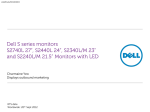
User’s Manual
VTG 150, VTG 200
Video Test Generators
www.extron.com
Extron Electronics, USA
Extron Electronics, Europe
Extron Electronics, Asia
Extron Electronics, Japan
1230 South Lewis Street
Anaheim, CA 92805
USA
714.491.1500
Fax 714.491.1517
Beeldschermweg 6C
3821 AH Amersfoort
The Netherlands
+31.33.453.4040
Fax +31.33.453.4050
135 Joo Seng Road, #04-01
PM Industrial Building
Singapore 368363
+65.6383.4400
Fax +65.6383.4664
Daisan DMJ Building 6F
3-9-1 Kudan Minami
Chiyoda-ku, Tokyo 102-0074 Japan
+81.3.3511.7655
Fax +81.3.3511.7656
© 2002 Extron Electronics. All rights reserved.
68-194-01
Printed in the USA
Precautions
Safety Instructions • English
This symbol is intended to alert the user of important
operating and maintenance (servicing) instructions in
the literature provided with the equipment.
This symbol is intended to alert the user of the presence
of uninsulated dangerous voltage within the product's
enclosure that may present a risk of electric shock.
Caution
Read Instructions • Read and understand all safety and operating
instructions before using the equipment.
Retain Instructions • The safety instructions should be kept for future
reference.
Follow Warnings • Follow all warnings and instructions marked on the
equipment or in the user information.
Avoid Attachments • Do not use tools or attachments that are not
recommended by the equipment manufacturer because they may be
hazardous.
Power sources • This equipment should be operated only from the power source
indicated on the product. This equipment is intended to be used with a main
power system with a grounded (neutral) conductor. The third (grounding) pin is
a safety feature, do not attempt to bypass or disable it.
Power disconnection • To remove power from the equipment safely, remove all
power cords from the rear of the equipment, or the desktop power module (if
detachable), or from the power source receptacle (wall plug).
Power cord protection • Power cords should be routed so that they are not likely to
be stepped on or pinched by items placed upon or against them.
Servicing • Refer all servicing to qualified service personnel. There are no userserviceable parts inside. To prevent the risk of shock, do not attempt to service
this equipment yourself because opening or removing covers may expose you to
dangerous voltage or other hazards.
Slots and openings • If the equipment has slots or holes in the enclosure, these are
provided to prevent overheating of sensitive components inside. These openings
must never be blocked by other objects.
Lithium battery • There is a danger of explosion if battery is incorrectly replaced.
Replace it only with the same or equivalent type recommended by the
manufacturer. Dispose of used batteries according to the manufacturer's
instructions.
Consignes de Sécurité • Français
Ce symbole sert à avertir l’utilisateur que la
documentation fournie avec le matériel contient des
instructions importantes concernant l’exploitation et
la maintenance (réparation).
Ce symbole sert à avertir l’utilisateur de la présence
dans le boîtier de l’appareil de tensions dangereuses
non isolées posant des risques d’électrocution.
Attention
Lire les instructions• Prendre connaissance de toutes les consignes de
sécurité et d’exploitation avant d’utiliser le matériel.
Conserver les instructions• Ranger les consignes de sécurité afin de
pouvoir les consulter à l’avenir.
Respecter les avertissements • Observer tous les avertissements et
consignes marqués sur le matériel ou présentés dans la documentation
utilisateur.
Eviter les pièces de fixation • Ne pas utiliser de pièces de fixation ni
d’outils non recommandés par le fabricant du matériel car cela
risquerait de poser certains dangers.
Avertissement
Alimentations• Ne faire fonctionner ce matériel qu’avec la source d’alimentation
indiquée sur l’appareil. Ce matériel doit être utilisé avec une alimentation
principale comportant un fil de terre (neutre). Le troisième contact (de mise à la
terre) constitue un dispositif de sécurité : n’essayez pas de la contourner ni de la
désactiver.
Déconnexion de l’alimentation• Pour mettre le matériel hors tension sans danger,
déconnectez tous les cordons d’alimentation de l’arrière de l’appareil ou du
module d’alimentation de bureau (s’il est amovible) ou encore de la prise secteur.
Protection du cordon d’alimentation • Acheminer les cordons d’alimentation de
manière à ce que personne ne risque de marcher dessus et à ce qu’ils ne soient
pas écrasés ou pincés par des objets.
Réparation-maintenance • Faire exécuter toutes les interventions de réparationmaintenance par un technicien qualifié. Aucun des éléments internes ne peut être
réparé par l’utilisateur. Afin d’éviter tout danger d’électrocution, l’utilisateur ne
doit pas essayer de procéder lui-même à ces opérations car l’ouverture ou le
retrait des couvercles risquent de l’exposer à de hautes tensions et autres dangers.
Fentes et orifices • Si le boîtier de l’appareil comporte des fentes ou des orifices,
ceux-ci servent à empêcher les composants internes sensibles de surchauffer. Ces
ouvertures ne doivent jamais être bloquées par des objets.
Lithium Batterie • Il a danger d'explosion s'll y a remplacment incorrect de la
batterie. Remplacer uniquement avec une batterie du meme type ou d'un ype
equivalent recommande par le constructeur. Mettre au reut les batteries usagees
conformement aux instructions du fabricant.
Sicherheitsanleitungen • Deutsch
Dieses Symbol soll dem Benutzer in der im
Lieferumfang enthaltenen Dokumentation
besonders wichtige Hinweise zur Bedienung und
Wartung (Instandhaltung) geben.
Dieses Symbol soll den Benutzer darauf aufmerksam
machen, daß im Inneren des Gehäuses dieses
Produktes gefährliche Spannungen, die nicht isoliert
sind und die einen elektrischen Schock verursachen
können, herrschen.
Achtung
Lesen der Anleitungen • Bevor Sie das Gerät zum ersten Mal verwenden,
sollten Sie alle Sicherheits-und Bedienungsanleitungen genau
durchlesen und verstehen.
Aufbewahren der Anleitungen • Die Hinweise zur elektrischen Sicherheit
des Produktes sollten Sie aufbewahren, damit Sie im Bedarfsfall darauf
zurückgreifen können.
Befolgen der Warnhinweise • Befolgen Sie alle Warnhinweise und
Anleitungen auf dem Gerät oder in der Benutzerdokumentation.
Keine Zusatzgeräte • Verwenden Sie keine Werkzeuge oder Zusatzgeräte,
die nicht ausdrücklich vom Hersteller empfohlen wurden, da diese eine
Gefahrenquelle darstellen können.
Vorsicht
Stromquellen • Dieses Gerät sollte nur über die auf dem Produkt angegebene
Stromquelle betrieben werden. Dieses Gerät wurde für eine Verwendung mit
einer Hauptstromleitung mit einem geerdeten (neutralen) Leiter konzipiert. Der
dritte Kontakt ist für einen Erdanschluß, und stellt eine Sicherheitsfunktion dar.
Diese sollte nicht umgangen oder außer Betrieb gesetzt werden.
Stromunterbrechung • Um das Gerät auf sichere Weise vom Netz zu trennen,
sollten Sie alle Netzkabel aus der Rückseite des Gerätes, aus der externen
Stomversorgung (falls dies möglich ist) oder aus der Wandsteckdose ziehen.
Schutz des Netzkabels • Netzkabel sollten stets so verlegt werden, daß sie nicht
im Weg liegen und niemand darauf treten kann oder Objekte darauf- oder
unmittelbar dagegengestellt werden können.
Wartung • Alle Wartungsmaßnahmen sollten nur von qualifiziertem
Servicepersonal durchgeführt werden. Die internen Komponenten des Gerätes
sind wartungsfrei. Zur Vermeidung eines elektrischen Schocks versuchen Sie in
keinem Fall, dieses Gerät selbst öffnen, da beim Entfernen der Abdeckungen die
Gefahr eines elektrischen Schlags und/oder andere Gefahren bestehen.
Schlitze und Öffnungen • Wenn das Gerät Schlitze oder Löcher im Gehäuse
aufweist, dienen diese zur Vermeidung einer Überhitzung der empfindlichen
Teile im Inneren. Diese Öffnungen dürfen niemals von anderen Objekten
blockiert werden.
Litium-Batterie • Explosionsgefahr, falls die Batterie nicht richtig ersetzt wird.
Ersetzen Sie verbrauchte Batterien nur durch den gleichen oder einen
vergleichbaren Batterietyp, der auch vom Hersteller empfohlen wird. Entsorgen
Sie verbrauchte Batterien bitte gemäß den Herstelleranweisungen.
Instrucciones de seguridad • Español
Este símbolo se utiliza para advertir al usuario sobre
instrucciones importantes de operación y
mantenimiento (o cambio de partes) que se desean
destacar en el contenido de la documentación
suministrada con los equipos.
Este símbolo se utiliza para advertir al usuario sobre la
presencia de elementos con voltaje peligroso sin
protección aislante, que puedan encontrarse dentro de
la caja o alojamiento del producto, y que puedan
representar riesgo de electrocución.
Precaucion
Leer las instrucciones • Leer y analizar todas las instrucciones de
operación y seguridad, antes de usar el equipo.
Conservar las instrucciones • Conservar las instrucciones de seguridad
para futura consulta.
Obedecer las advertencias • Todas las advertencias e instrucciones
marcadas en el equipo o en la documentación del usuario, deben ser
obedecidas.
Evitar el uso de accesorios • No usar herramientas o accesorios que no
sean especificamente recomendados por el fabricante, ya que podrian
implicar riesgos.
FCC Class B Notice
Warning
Advertencia
Alimentación eléctrica • Este equipo debe conectarse únicamente a la fuente/tipo
de alimentación eléctrica indicada en el mismo. La alimentación eléctrica de este
equipo debe provenir de un sistema de distribución general con conductor
neutro a tierra. La tercera pata (puesta a tierra) es una medida de seguridad, no
puentearia ni eliminaria.
Desconexión de alimentación eléctrica • Para desconectar con seguridad la
acometida de alimentación eléctrica al equipo, desenchufar todos los cables de
alimentación en el panel trasero del equipo, o desenchufar el módulo de
alimentación (si fuera independiente), o desenchufar el cable del receptáculo de
la pared.
Protección del cables de alimentación • Los cables de alimentación eléctrica se
deben instalar en lugares donde no sean pisados ni apretados por objetos que se
puedan apoyar sobre ellos.
Reparaciones/mantenimiento • Solicitar siempre los servicios técnicos de personal
calificado. En el interior no hay partes a las que el usuario deba acceder. Para
evitar riesgo de electrocución, no intentar personalmente la reparación/
mantenimiento de este equipo, ya que al abrir o extraer las tapas puede quedar
expuesto a voltajes peligrosos u otros riesgos.
Ranuras y aberturas • Si el equipo posee ranuras o orificios en su caja/alojamiento,
es para evitar el sobrecalientamiento de componentes internos sensibles. Estas
aberturas nunca se deben obstruir con otros objetos.
Batería de litio • Existe riesgo de explosión si esta batería se coloca en la posición
incorrecta. Cambiar esta batería únicamente con el mismo tipo (o su equivalente)
recomendado por el fabricante. Desachar las baterías usadas siguiendo las
instrucciones del fabricante.
This equipment has been tested and found to comply with the limits for a Class B digital
device, pursuant to part 15 of the FCC Rules. These limits are designed to provide reasonable
protection against harmful interference in a residential installation. This equipment generates,
uses and can radiate radio frequency energy and, if not installed and used in accordance with
the instructions, may cause harmful interference to radio communications. However, there is
no guarantee that the interference will not occur in a particular installation. If this equipment
does cause harmful interference to radio or television reception, which can be determined by
turning the equipment off and on, the user is encouraged to try to correct the interference by
one or more of the following measures:
• Reorient or relocate the receiving antenna.
• Increase the separation between the equipment and receiver.
• Connect the equipment into an outlet on a circuit different from that to which the receiver
is connected.
• Consult the dealer or an experienced radio/TV technician for help.
This unit was tested with shielded cables on the peripheral devices. Shielded cables must be
used with the unit to ensure compliance.
Extron’s Warranty
Extron Electronics warrants this product against defects in materials and workmanship for a
period of three years from the date of purchase. In the event of malfunction during the
warranty period attributable directly to faulty workmanship and/or materials, Extron
Electronics will, at its option, repair or replace said products or components, to whatever extent
it shall deem necessary to restore said product to proper operating condition, provided that it is
returned within the warranty period, with proof of purchase and description of malfunction to:
USA, Canada, South America,
and Central America:
Extron Electronics
1230 South Lewis Street
Anaheim, CA 92805, USA
Asia:
Extron Electronics, Asia
135 Joo Seng Road, #04-01
PM Industrial Bldg.
Singapore 368363
Europe, Africa, and the Middle East:
Extron Electronics, Europe
Beeldschermweg 6C
3821 AH Amersfoort
The Netherlands
Japan:
Extron Electronics, Japan
Daisan DMJ Bldg. 6F,
3-9-1 Kudan Minami
Chiyoda-ku, Tokyo 102-0074
Japan
This Limited Warranty does not apply if the fault has been caused by misuse, improper
handling care, electrical or mechanical abuse, abnormal operating conditions or non-Extron
authorized modification to the product.
If it has been determined that the product is defective, please call Extron and ask for an
Applications Engineer at (714) 491-1500 (USA), 31.33.453.4040 (Europe), 65.6383.4400 (Asia),
or 81.3.3511.7655 (Japan) to receive an RA# (Return Authorization number). This will begin
the repair process as quickly as possible.
Units must be returned insured, with shipping charges prepaid. If not insured, you assume
the risk of loss or damage during shipment. Returned units must include the serial number
and a description of the problem, as well as the name of the person to contact in case there
are any questions.
Extron Electronics makes no further warranties either expressed or implied with respect to the
product and its quality, performance, merchantability, or fitness for any particular use. In no
event will Extron Electronics be liable for direct, indirect, or consequential damages resulting
from any defect in this product even if Extron Electronics has been advised of such damage.
Please note that laws vary from state to state and country to country, and that some
provisions of this warranty may not apply to you.
Contents
Introduction to VTG 150 & VTG 200 ..................................... Chapter 1
Introduction .............................................................................. 1-1
VTG 150 Features ................................................................... 1-2
VTG 200 Features ................................................................... 1-2
Specifications .......................................................................... 1-2
Connecting the VTG Output Cables ..................................... Chapter 2
Connecting the VTG Output Cables ........................................ 2-1
15-Pin HD (VGA/XGA) Output ................................................. 2-1
15-Pin Apple/Mac II (VTG 150),
MacII/Quadra (VTG 200) Output ............................................. 2-2
9 Pin, TTL Output .................................................................... 2-2
RGB Output (BNC, Analog) ..................................................... 2-3
Composite vs. Separate H & V ........................................ 2-3
Sync on Red, Blue, or Green ........................................... 2-3
NTSC/PAL BNC Output (VTG 200 only) ................................. 2-3
13W3 Sun/SGI/IBM Output (VTG 200 only) ............................ 2-4
Adapting the VTG 150 to Other Standards ............................. 2-4
Monitors with a 13W3 Input Connector ............................ 2-4
Connecting TTL Output to an AT&T 6300 ........................ 2-5
Operating the Video Test Generator ..................................... Chapter 3
Operating the Video Test Generator ....................................... 3-1
Power On ......................................................................... 3-1
Timer LED ........................................................................ 3-1
Exit the Instructional Menu Cycle ..................................... 3-2
View the Scan Ranges ..................................................... 3-2
View the Scan Rates ........................................................ 3-2
Activate a Scan Rate ........................................................ 3-2
Change Scan Rate ........................................................... 3-3
Change Test Pattern ........................................................ 3-3
Change Test Pattern Color .............................................. 3-3
Auto-sequence the Test Patterns ..................................... 3-3
NTSC/PAL LED (VTG 200 only) ...................................... 3-3
Timer ................................................................................ 3-3
Add Sync to a Video Line ................................................. 3-4
Sync Output Selection ...................................................... 3-4
Power Off ......................................................................... 3-5
Application Information ........................................................ Chapter 4
VTG Formats ........................................................................... 4-1
Video Test Patterns ................................................................. 4-3
Setting Up Large Screen Projection Systems ......................... 4-5
Video Setup Guide .................................................................. 4-6
Monitor Applications ................................................................ 4-7
Troubleshooting ....................................................................... 4-9
Page i
VTG 200 RS-232 Control and Software ................................ Chapter 5
VTG 200 RS-232 Control and Connection to Computer ......... 5-1
Host/VTG 200 Communications ....................................... 5-2
Using the Command/Response Table ............................. 5-2
Command/Response Table ..................................................... 5-3
Definitions and Abbreviations .......................................... 5-3
Error Code Descriptions ................................................... 5-3
VTG 200 Control Program ....................................................... 5-5
Installing the Software ...................................................... 5-5
Using the Software ........................................................... 5-5
Reference Material ............................................................ Appendix A
VTG Software Updates ............................................................ A-1
Part Numbers .......................................................................... A-1
Adapters ........................................................................... A-1
Pre-cut BNC Cables ......................................................... A-1
VGA Male-Female Cables ................................................ A-1
Mac/Quadra Male-Female Cables ................................... A-2
Male-to-Female Cables (Sun/SGI) ................................... A-2
VGA 15-pin HD Male to 15-pin HD Male Cables ............. A-2
Mac/Quadra 15-pin Male to 15-pin Male Cables ............. A-2
13W3 Male-to-Male Cables (Sun/SGI) ............................. A-2
All trademarks mentioned in this manual are the properties of their respective owners.
68-194-01 Rev. C
Printed in the USA
04 02
Extron VTG 150 & VTG 200
User’s Manual
1
Chapter One
Introduction
Introduction
Legend of Icons
___ Important information – for example, an action or a step that
must be done before proceeding.
___ A Warning – possible damage could occur.
_ A Note, a Hint, or a Tip that may be helpful.
__ Possible Electrostatic Discharge (ESD) damage could result
from touching electronic components.
__ Additional information may be referenced in another section,
or in another document.
Page ii
VTG 150 Features
VTG 200 Features
Specifications
Introduction
Introduction
Introduction
VTG 150 Features
The Extron VTG 150 and VTG 200 Video Test Generators
reproduce computer video signals with patterns for testing
and repairing computer monitors, LCD panels, interfaces and
large screen displays. They are also used to setup and
simulate computer video for system installations.
Both the VTG 150 and the
VTG 200 have 16 selectable
test patterns for setting and
testing geometry, focus,
convergence, gray scale and
other parameters. After a test
pattern has been selected, the
color of each pattern may be
changed to display in the
colors white, black, red, green,
blue, cyan, magenta and
yellow.
•
Easy operation - When power is applied to the VTG, the LCD
displays a series of instructional menus.
•
Output connectors provide connection to RGB (BNC), TTL,
Macintosh and VGA/XGA devices.
•
Sync output can be composite H/V; separate H & V; Sync on
Green; or sync on red, green, and blue.
•
Automatic time-out to prevent video burn-in
•
Pre-loaded scan rates - The VTG 150 has been pre-loaded
with the most popular video scan rates.
•
Sixteen test patterns with selectable color combination
•
Upgrades and options - As new scan formats are introduced,
the VTG 150 can be sent to Extron to be upgraded.
•
Automatic test pattern sequencing for burn-in applications of
display and video processing equipment.
VTG 200 Features
The VTG 200 Video Test Generator has all of the features of
the VTG 150 listed above plus:
•
13W3 output connector for Sun, SGI, IBM Power PC and
NEXT type monitors
•
NTSC/PAL BNC output connector
•
SMPTE color bar and PLUGE test pattern for NTSC/PAL
•
RS-232 connector supports VTG 200 control and field
loading of scan rates (Extron or user-supplied scan rates).
•
Internal power supply operates on any AC line voltage input in
the 100-240VAC, 50/60Hz range.
•
Field programmable and upgradeable by Extron or the user as
new scan rates are introduced by computer and graphics card
manufacturers
Specifications
The VTG 200 is field programmable through its RS-232 port.
New scan rates can be added by the user as they are
encountered on new equipment. The included Windowscompatible software simplifies the programming.
This user’s manual provides the information necessary to
operate the VTG 150 and VTG 200 video test generators. A
label on the bottom of each unit provides quick-reference
operating instructions.
Page 1-1
Extron • VTG 150 & VTG 200 • User’s Manual
Video
Bandwidth ..................................... 450 MHz (-3dB)
Video signal characteristics
Dot clock ........................................
Pixel clock accuracy ....................
Scan rate accuracy .......................
Frequency range ..........................
Rise/fall time ...............................
230 MHz
0.02 MHz
±2%
15 kHz to 127 kHz
<1.2 nS
Extron • VTG 150 & VTG 200 • User’s Manual
Page 1-2
Introduction
Video output
Number/signal type
VTG 150 ................................... 1 RGBHV, RGBS, RGsB, RsGsBs
VTG 200 ................................... 1 RGBHV, RGBS, RGsB, RsGsBs, NTSC/PAL
composite video
Connectors
VTG 150 ................................... 5 BNC female, 1 15-pin HD female, 1 15-pin
D female, 1 9-pin D female
VTG 200 ................................... 5 BNC female, 1 BNC female, 1 15-pin HD
female, 1 15-pin D female, 1 13W3 D
female, 1 9-pin D female
Rates
VTG 150 ................................... VGA-UXGA, Apple/Mac/Quadra, TTL,
HDTV
VTG 200 ................................... VGA-UXGA, Apple/Mac/Quadra, Sun/
SGI/NeXT/IBM Power PC, TTL, HDTV
Maximum level ............................
Impedance .....................................
Return loss ....................................
DC offset ........................................
1V p-p
75 ohms
-30dB @ 5 MHz
±5mV maximum
Control/remote — test generator (VTG 200 only)
Serial control port ....................... RS-232, 9-pin female D connector
Baud rate and protocol .............. 9600, 8-bit, 1 stop bit, no parity
Serial control pin configurations
2 = TX, 3 = RX, 5 = GND
Program control ........................... Extron’s control program for Windows®
Extron’s Simple Instruction Set™ – SIS™
Extron’s Advanced Instruction Set™ –
AIS™
General
Power ............................................. 100VAC to 240VAC, 50/60 Hz, 9 watts,
VTG 150 ................................... external, auto-switchable; to 9.0VDC, 0.6 A
VTG 200 ................................... internal, auto-switchable
Temperature/humidity ............. Storage -40° to +158°F (-40° to +70°C) /
10% to 90%, non-condensing
Operating +32° to +122°F (0° to +50°C) /
10% to 90%, non-condensing
Rack mount ................................... No
Enclosure type ............................. Metal
Enclosure dimensions
VTG 150 ................................... 4.7" H x 4.6" W x 1.7" D
11.9 cm H x 11.7 cm W x 4.3 cm D
(5.5” (14 cm) H includes connectors)
VTG 200 ................................... 6.3" H x 9.0" W x 2.0" D
16.0 cm H x 22.9 cm W x 5.1 cm D
(7.0” (17.8 cm) H including connectors.)
Product weight
VTG 150 ................................... 1.7 lbs (0.8 kg)
VTG 200 ................................... 3.3 lbs (1.5 kg)
Shipping weight
VTG 150 ................................... 4 lbs (1.8 kg)
VTG 200 ................................... 7 lbs (3.2 kg)
Vibration ........................................ ISTA/NSTA 1A in carton (International
Safe Transit Association)
Listings ........................................... UL, CUL
Compliances ................................. CE, FCC Class B
MTBF .............................................. 30,000 hours
Warranty ........................................ 3 years parts and labor
Page 1-3
Specifications are subject to change without notice.
Extron • VTG 150 & VTG 200 • User’s Manual
Extron VTG 150 & VTG 200
User’s Manual
2
Chapter Two
Connecting the VTG
Output Cables
15-Pin HD (VGA/XGA) Output
15-Pin Apple/Mac II (VTG 150), MacII/Quadra (VTG 200) Output
9 Pin, TTL Output
RGB Output (BNC, Analog)
NTSC/PAL BNC Output (VTG 200 only)
13W3 Sun/SGI/IBM Output (VTG 200 only)
Adapting the VTG 150 to Other Standards
Connecting the VTG Output Cables
Connecting the VTG Output Cables
100-240 VAC
VTG 200 ↑
VTG 150 ↓
The VTG 200 (above)
provides six sets of
video output connectors;
the VTG 150 (at right)
provides four sets. Each
connector is marked for
its video application.
Connecting the VTG Output Cables
15-Pin Apple/Mac II (VTG 150), MacII/Quadra (VTG 200)
Output
All scan rate signals go to the VGA/
XGA (15-pin HD), Apple/MacII/
Quadra (15-pin) and BNC
connectors. The BNC output is individually buffered, allowing
devices to be connected to BNC and Apple/MacII/Quadra
outputs at the same time. However, because the VGA/XGA
and Apple/MacII/Quadra outputs are in parallel, they should
not be connected at the same time.
_ If devices are connected to both 15-pin outputs (VGA/XGA &
Apple/MacII/Quadra) simultaneously, the double termination
will result in a loss of brightness.
See the table of video scan formats on page 4-1 and choose
the one to be used to simulate your computer. Then connect
the appropriate cables to the device to be tested. (e.g.
projector, switcher, etc.)
15-Pin HD (VGA/XGA) Output
One connector is provided for the VGA/
XGA because the pin configurations are
identical. All scan rate signals go to the
VGA/XGA (15-pin HD), Apple/MacII/Quadra (15-pin) and BNC
connectors. The BNC output is individually buffered, allowing
devices to be connected to BNC and VGA/XGA outputs at the
same time. However, because the VGA/XGA and Apple/
MacII/Quadra outputs are in parallel, they should not be
connected at the same time.
_ If devices are connected to both 15-pin outputs VGA/XGA &
Apple/MacII/Quadra simultaneously, the double termination
will result in a loss of brightness.
The pin assignments for the Apple/MacII/Quadra connector
are as follows:
Pin
Pin
Pin
Pin
Pin
1 = Red Ground
2 = Red
3 = Composite Sync
5 = Green
6 = Green Ground
Pin 9 = Blue
Pin 11 = C/V Sync Ground
Pin 12 = V. Sync
Pin 13 = Blue Ground
Pin 14 = H. Ground
Pin 15 = H. Sync
9 Pin, TTL Output
A 9 pin “D” style connector provides all
TTL signal outputs. These outputs may
be selected from the TTL Scan Rates menu.
Pin
Pin
Pin
Pin
1 = Ground
2 = Red Intensity
3 = Red
4 = Green
Pin
Pin
Pin
Pin
Pin
5 = Blue
6 = Green Intensity
7 = Blue Intensity
8 = H. Sync
9 = V. Sync
The pin assignments for the 15-pin HD are as follows:
Pin
Pin
Pin
Pin
Pin
1
2
3
6
7
=
=
=
=
=
Red
Green
Blue
Red Ground
Green Ground
Pin 8 = Blue Ground
Pin 10 = Ground
Pin 13 = H. Sync
Pin 14 = V. Sync
_ When running TTL rates from outputs other than the 9-pin TTL
output, the test patterns may appear dim, distorted or
otherwise unlike the output from the 9 pin connector. This is
normal, due to the signal characteristics of TTL video signals.
Thus, for exact TTL signal duplication, only use the 9 pin TTL
output.
The sync available on pins 13 and 14 is dependent on the
position of the H/HV switch. With the switch in the HV (down)
position, composite sync is available on pin 13. With the
switch in the H (up) position, separate H and V sync is
available on pins 13 and 14.
Page 2-1
Extron • VTG 150 & VTG 200 • User’s Manual
Extron • VTG 150 & VTG 200 • User’s Manual
Page 2-2
Connecting the VTG Output Cables
Connecting the VTG Output Cables
RGB Output (BNC, Analog)
The RGB BNC output
provides red, green, and blue
video at 0.7 volts peak to peak and horizontal and vertical
sync at TTL levels on the H/HV and V BNC connectors.
Those five BNC connectors, together with the 2-position
switch, can be used four ways:
•
RGB with composite horizontal and vertical sync (4-cables)
•
RGB with separate horizontal and vertical sync (5-cables)
•
RGB with Sync on Green (3-cables)
•
RGB with sync on red, green, and blue (3-cables)
Composite vs. Separate H & V
The vertical sync is provided on the BNC connector marked
V. Depending on the position of the toggle switch, the H/HV
connector can have either a separate horizontal sync, or a
composite horizontal/vertical sync. For example: for
composite sync output, put the toggle switch in the HV
position and don't use the V connector. For separate H & V
sync output, put the switch in the H position and connect
cables to both the H/HV and the V connectors.
Sync on Red, Blue, or Green
Sync on Green may be removed or added for all scan
formats. If normal operation of the selected scan rate is Sync
On Green, that is what the VTG will output. However, the
sync may be removed by following the instructions in Chapter
3.
The sync polarity (positive or negative) of the BNC H & V
output is identical to that of the selected computer.
To output negative composite sync at all times (optimum for
converging video projectors), place the back panel toggle
switch in the HV position. All frequencies may be output on
the BNC connectors.
NTSC/PAL BNC Output (VTG 200 only)
The VTG 200 NTSC/PAL BNC connector provides composite
video output when an NTSC or PAL scan rate is selected.
Page 2-3
Extron • VTG 150 & VTG 200 • User’s Manual
13W3 Sun/SGI/IBM Output (VTG 200
only)
The pin assignments for the 13W3
connector are:
Pin A1 = Red
Pin A2 = Green
Pin A3 = Blue
Sync pin assignments vary by manufacturer as follows:
Signal
Sun
SGI
IBM
NXT
H/HV
V
Ground
5
NC
10
3
4
10
5
9
10
A2 (SOG)
NC
10
Adapting the VTG 150 to Other Standards
For some applications, the unit
to be tested may not have
connectors that match those
provided on the VTG 150.
Adaptor cables can be made up
to serve this need. Following are some examples.
Monitors with a 13W3 Input Connector
When connecting a VTG 150 to a monitor that uses the 13W3
connector, use an adapter cable with the following, 4 or 5
BNC configuration:
BNC
Cable
13W3 Connector Pin Numbers
SUN
SGI
IBM
NEXT
Red
Green
Blue
A1
A2
A3
A1
A2
A3
A1
A2
A3
A1
A2 (SOG)
A3
H/HV
V
Ground
5
NC
10
3
4
10
5
9
10
NC
NC
10
Extron • VTG 150 & VTG 200 • User’s Manual
Page 2-4
Connecting the VTG Output Cables
Connecting TTL Output to an AT&T 6300
When using the VTG 150 TTL output with an AT&T 6300
monitor, an adapter cable is needed with the following
configuration:
9-pin
Signal
25-Pin
1
Ground
14 & 15
3
Red
4
4
Green
5
5
Blue
6
6
Intensity
7
8
H Sync
1
9
V Sync
3
Extron VTG 150 & VTG 200
User’s Manual
3
Chapter Three
Operating the Video Test Generator
Operating the Video Test Generator
Page 2-5
Extron • VTG 150 & VTG 200 • User’s Manual
Operating the Video Test Generator
Operating the Video Test Generator
Operating the Video Test Generator
Connect the video test generator to the device to be tested.
(See Connecting the VTG Output Cables in chapter 2.)
Exit the Instructional Menu Cycle
To exit the instructional menu cycle, press the ▼ or ▲ button.
A scan range will be displayed on the LCD screen.
View the Scan Ranges
To view the available scan ranges (i.e. TTL, VGA, Mac), hold
the MODE/ON button down and press the ▼ or ▲ button. The
LCD will display a different scan range each time the button
is pressed. Stop when the desired scan range is displayed by
the LCD.
_ There are several scan rates within each scan range. If the
desired scan range is unknown, the tables in chapter 4 may be
helpful. However, be aware that an updated VTG may offer
scan rates that are not listed in the tables. Stepping through
the scan ranges and scan rates on the VTG device will show
all available scan formats.
Power On
Press the MODE/ON button to
turn VTG power On. The LCD
display cycles through six
instructional menus (Main Menu)
that tell how to operate the video
test generator. The first is the
identification screen (shown in the
picture above). The other five are
shown to the right.
Timer LED
The color of the Timer LED
identifies the current operating
state of the VTG. The possible
Timer LED colors are:
•
•
•
•
•
Page 3-1
Off = VTG inactive (no scan rate selected)
Green = VTG active (scan rate is selected), timer is running.
Red = VTG active (scan rate is selected), timer is disabled.
Blinking red & green = Time-out occurred, video is muted.
Orange = VTG is in Auto-sequence mode, timer is disabled.
Extron • VTG 150 & VTG 200 • User’s Manual
View the Scan Rates
Press either the ▼ or ▲ button to step through the scan rates
(i.e. CGA, Mac II, XGA). Continuously pressing the ▼ or ▲
button will step through all scan rates of all scan ranges. To
change to a different scan range while viewing the scan
rates, press and hold the MODE/ON button and press the ▼
or ▲ button.
Activate a Scan Rate
Press the SELECT button when the desired scan rate
appears on the LCD readout. When the selection is made,
the Timer LED will turn green and a dot test pattern will
appear on the output screen of the device under test. This is
test pattern #1.
To return to the main menu after activating a scan rate
(cancel the scan rate), press the SELECT button.
Extron • VTG 150 & VTG 200 • User’s Manual
Page 3-2
Operating the Video Test Generator
Operating the Video Test Generator
Unless it is disabled, the timer will begin its countdown to
time-out when the Timer LED turns green (indicating that a
single test pattern is being displayed). The countdown
restarts each time any button is pressed.
_ When a time-out occurs, only the video display will be cut off;
the sync will remain active, even while the video is muted, thus
convergence settings will not be lost.
Change Scan Rate
An active scan rate can be changed at any time by holding
the SELECT button and pressing the ▼ or ▲ button.
Add Sync to a Video Line
Change Test Pattern
Sync may be added on the green video channel by holding
down the MODE/ON button and pressing the SELECT button.
The Sync LED will turn green. Repeat this procedure to add
sync to all three video channels. The Sync LED will then turn
red. Repeating this procedure one more time will then return
the VTG to separate sync output, and the LED will be off.
With an active scan rate (Timer LED = green), press the ▼ or
▲ button repeatedly to step through the available test
patterns. The test patterns will appear in numerical order
1-16 as shown in chapter 4.
Change Test Pattern Color
While displaying a test pattern, hold the MODE/ON button
and press the ▲ button to step through the 8 color
combinations.
Sync Output Selection
The default sync output depends on the scan format. That is,
if Sync on Green is normal operation for the chosen format,
that is what the VTG will provide. Sync output can be
configured four ways to accommodate the output device.
Auto-sequence the Test Patterns
To set the VTG to Auto-sequence mode, a scan rate must be
active; hold MODE/ON and press the ▼ button. The Timer
LED will turn orange in Auto-sequence mode and the 16 test
patterns will cycle sequentially at 5 second intervals. To exit
Auto-sequence mode, hold MODE/ON and press the ▼
button. The Timer LED will turn green and a single test
pattern will be displayed on the output screen.
NTSC/PAL LED (VTG 200 only)
Normally off, this LED will turn green when an NTSC or PAL
scan rate is activated indicating that a test pattern is available
at the NTSC/PAL BNC connector.
Timer
The VTG timer will time-out (if not disabled) when a test
pattern has been displayed for five minutes to prevent CRT
burn-in. When this happens, the LED will flash red and green
alternately. To turn the video back on, press the MODE/ON
button. The timer feature can be disabled by pressing the ▼
and ▲ buttons at the same time. When disabled, the Timer
LED will turn red.
Page 3-3
Extron • VTG 150 & VTG 200 • User’s Manual
•
•
•
•
RGB
RGB
RGB
RGB
with composite horizontal and vertical sync
with separate horizontal and vertical sync
with Sync on Green
with sync on red, green, and blue
The vertical sync is provided on the BNC connector marked
V. Depending on the position of the toggle switch, the H/HV
connector can have either a separate horizontal sync, or a
composite horizontal/vertical sync.
For example: for composite sync output, put the toggle
switch in the HV position and don't use the V connector. For
separate H & V sync output, put the switch in the H position
and connect cables to both the H/HV and the V connectors.
For details, see chapter 2.
Power Off
The VTG power may be turned off by simultaneously pressing
the ▼ and ▲ buttons when the VTG is in the inactive state
(the Timer LED is off). If the VTG is active (the Timer LED is
on), press and release SELECT first.
Extron • VTG 150 & VTG 200 • User’s Manual
Page 3-4
Extron VTG 150 & VTG 200
User’s Manual
4
Chapter Four
Application Information
VTG Formats
Video Test Patterns
Setting Up Large Screen Projection Systems
Video Setup Guide
Monitor Applications
Troubleshooting
Page 3-5
Application Information
150# 200# Format
IBM Power PC, cont’d
VTG Formats
The table below lists the formats in the order in which they
appear on the LCD screen when using the ▲ button to step
through the choices. Use the ▼ button to go backward. To
skip from one “range” or set of scan rates to the next, hold
the MODE button while pressing ▼ or ▲ .
The columns labeled 150# and 200# are the format numbers
for the VTG 150 and the VTG 200. NA in the 150# column
indicates the format is not applicable to the VTG 150.
150# 200# Format
Pixel x Line
TTL Scan Rates - CGA, MDA, EGA and Mac
1 ......... 1
2 ......... 2
3 ......... 3
4 ......... 4
5 ......... 5
.. CGA ................................... 640
.. MDA ................................... 720
.. EGA ................................... 640
.. MAC CL ............................... 512
.. MAC SE ............................... 512
Hor. kHz Ver. Hz
x
x
x
x
x
200 .......... 15.75 .......... 60
350 ........... 18.4 ........... 50
350 ........... 21.8 ........... 60
342 ........... 22.2 ........... 60
342 ........... 22.2 ........... 60
x
x
x
x
x
x
x
x
x
x
x
x
x
x
x
x
x
x
x
x
x
x
350 ........... 31.5 ........... 70
400 ........... 31.5 ........... 70
480 ........... 31.5 ........... 60
768 ........... 35.5 ........ 87/43
600 ........... 35.2 ........... 56
480 ........... 37.9 ........... 72
768 ........... 48.4 ........... 60
768 ........... 56.4 ........... 70
600 ........... 37.9 ........... 60
600 ........... 48.1 ........... 72
400 ........... 37.9 ........... 85
768 ........... 60.0 ........... 75
768 ........... 68.7 ........... 85
864 ........... 67.5 ........... 75
1024 ......... 64.0 ........... 60
1024 ......... 91.1 ........... 85
1200 ......... 75.0 ........... 60
1200 ......... 87.5 ........... 70
1200 ........ 106.3 .......... 85
768 ........... 57.0 ........... 70
768 ........... 61.1 ........... 76
222 ........... 31.5 .......... 120
x
x
x
x
x
x
x
x
x
192 ........... 15.7 ........... 60
384 ........... 24.5 ........... 60
480 ........... 35.0 ........... 67
624 ........... 49.7 ........... 75
768 ........... 60.2 ........... 75
870 ........... 68.7 ........... 75
624 ........... 44.9 ........... 67
768 ........... 48.0 ........... 60
768 ........... 48.0 ........... 60
VGA, VESA and XGA Scan Rates
6 ......... 6
7 ......... 7
8 ......... 8
9 ......... 9
10 ....... 10
11 ....... 11
12 ....... 12
13 ....... 13
14 ....... 14
15 ....... 15
16 ....... 16
17 ....... 17
18 ....... 18
19 ....... 19
20 ....... 20
21 ....... 21
22 ....... 22
NA ....... 23
NA ....... 24
23 ....... 25
24 ....... 26
25 ....... 27
.. VGA1 ................................. 640
.. VGA2 ................................. 640
.. VGA3 ................................. 640
.. 8514A ............................... 1024
.. VESA1 ............................... 800
.. VESA2 ............................... 640
.. VESA3 ............................. 1024
.. VESA4 ............................. 1024
.. VESA5 ............................... 800
.. VESA6 ............................... 800
.. VESA7 ............................... 640
.. VESA8 ............................. 1024
.. VESA9 ............................. 1024
.. VESA10 ........................... 1152
.. VESA11 ........................... 1280
.. VESA12 ........................... 1280
.. VESA13 ........................... 1600
.. VESA14 ........................... 1600
.. VESA15 ........................... 1600
.. XGA5 ............................... 1024
.. XGA6 ............................... 1024
.. Stereographics VGA ......... 640
Mac/Quadra Scan Rates
26 ....... 28
27 ....... 29
28 ....... 30
29 ....... 31
30 ....... 32
31 ....... 33
32 ....... 34
33 ....... 35
34 ....... 36
.. Apple II ............................... 560
.. Mac 12" .............................. 560
.. Mac 13" .............................. 640
.. Mac 16" .............................. 832
.. Mac 19" ............................ 1024
.. Mac 21" ............................ 1152
.. E-Machine .......................... 832
.. Super Mac ....................... 1024
.. Radius .............................. 1024
IBM Power PC
NA ....... 37 .. PPC 1/2 ........................... 1280 x 1024 ......... 81.3 ........... 77
NA ....... 38 .. PPC 3 ............................... 1280 x 1024 ......... 75.8 ........... 72
NA ....... 39 .. PPC 4 ............................... 1280 x 490 ........... 63.6 .......... 120
Page 4-1
Application Information
Extron • VTG 150 & VTG 200 • User’s Manual
NA ....... 40
NA ....... 41
NA ....... 42
NA ....... 43
NA ....... 44
.. PPC
.. PPC
.. PPC
.. PPC
.. PPC
Pixel x Line
5/6 ........................... 1024
7/8 ............................. 900
9/10 ......................... 1280
11 ............................. 1600
12 ............................. 1600
Hor. kHz Ver. Hz
x
x
x
x
x
768 ........... 61.1 ........... 76
720 ........... 81.1 .......... 111
1024 ......... 63.6 ........... 60
1280 ......... 61.1 ........... 76
1280 ......... 79.8 ........... 60
x
x
x
x
x
x
x
x
x
x
x
x
x
x
x
x
x
x
x
x
x
1024 ......... 63.9 ........... 60
1024 ......... 77.0 ........... 72
768 ........... 48.0 ........... 60
832 ........... 61.3 ........... 68
1024 ......... 63.4 ........... 60
800 ........... 63.9 ........... 76
900 ........... 61.8 ........... 66
900 ........... 71.7 ........... 76
1024 ......... 81.0 ........... 76
1280 ......... 89.3 ........... 67
1080 ......... 84.4 ........... 72
1200 ......... 87.1 ........... 70
1200 ......... 93.6 ........... 75
1024 ......... 69.9 ........... 66
864 ........... 54.0 ........... 60
768 ........... 57.4 ........... 72
1024 ......... 70.7 ........... 66
1024 ......... 77.1 ........... 72
768 ........... 56.3 ........... 70
1024 ......... 70.8 ........... 67
492 ........... 63.9 .......... 120
x
x
x
x
x
x
1800 ......... 105 ............ 76
1024 ......... 92.2 ......... 86.8
1280 .......... 95 ........... 70.9
1440 ......... 105 ............ 70
1536 ......... 115 .......... 71.8
2K ............. 127 ............ 60
x
x
x
x
x
x
x
x
525 .......... 15.73 ....... 60/30
575 ........... 15.6 ........ 50/25
525 .......... 15.73 .......... 60
575 ........... 15.6 ........... 50
350 ........... 25.5 ........... 60
532 ........... 37.7 ........... 67
768 ........... 60.2 ........... 75
870 ........... 68.7 ........... 75
x
x
x
x
x
x
1035 ........ 33.75 ....... 60/30
1080 ......... 67.5 ........... 60
1080 ......... 56.2 ........... 50
1080 ........ 33.75 ....... 60/30
1080 ........ 28.12 ....... 50/25
720 ........... 45.0 ........... 60
CAD Workstation Scan Rates
35 ....... 45
36 ....... 46
37 ....... 47
38 ....... 48
39 ....... 49
40 ....... 50
41 ....... 51
42 ....... 52
43 ....... 53
44 ....... 54
45 ....... 55
46 ....... 56
NA ....... 57
47 ....... 58
48 ....... 59
49 ....... 60
50 ....... 61
51 ....... 62
52 ....... 63
53 ....... 64
54 ....... 65
.. SGI ................................... 1280
.. SGI ................................... 1280
.. SGI Indigo ........................ 1024
.. NeXT ................................ 1120
.. IBM RS ............................ 1280
.. Apollo ............................... 1024
.. SUN .................................. 1152
.. SUN .................................. 1152
.. SUN .................................. 1280
.. SUN .................................. 1600
.. SUN .................................. 1920
.. SUN .................................. 1920
.. SUN .................................. 1920
.. DEC VR ........................... 1280
.. DEC VR ........................... 1024
.. DEC VRM ........................ 1024
.. DEC VR319 ..................... 1280
.. DEC VR320 ..................... 1280
.. NCD-17C ......................... 1024
.. IBM RS (PowerPC) ......... 1360
.. Stereographics SGI ......... 1280
Super High Res Scan Rates
55 ....... 66
56 ....... 67
57 ....... 68
58 ....... 69
59 ....... 70
60 ....... 71
.. Cornerstone ..................... 1600
.. Extron ............................... 1280
.. Extron ............................... 1600
.. Extron ............................... 1800
.. Extron ............................... 2048
.. Chromatics ......................... 2K
Other Scan Rates - NTSC, PAL, Etc.
61 ....... 72
62 ....... 73
NA ....... 74
NA ....... 75
63 ....... 76
64 ....... 77
65 ....... 78
66 ....... 79
.. NTSC Interlaced ................ 200
.. PAL Interlaced ................... 225
.. NTSC Non-Interlaced ........ 200
.. PAL Non-Interlaced ........... 225
.. HP 12" ................................ 640
.. IBM 3472 ........................... 720
.. RasterOps ........................ 1024
.. RasterOps ........................ 1152
HDTV Scan Rates
67 ....... 80
68 ....... 81
NA ....... 82
69 ....... 83
70 ....... 84
71 ....... 85
.. HDTV ............................... 1920
.. 1080 P .............................. 1920
.. 1080 P .............................. 1920
.. 1080 I ............................... 1920
.. 1080 I ............................... 1920
.. 720 P ................................ 1280
_ The listed pixel x line resolution represents the industry
published data and is not necessarily the exact resolution
provided by the VTG.
Extron • VTG 150 & VTG 200 • User’s Manual
Page 4-2
Application Information
Video Test Patterns
The following is a listing of the available test patterns and a
brief description of the purpose of each.
Pattern 1 — Dots 12 x 16 - Focus and Convergence
This pattern is effective for checking and adjusting focus
and convergence.
Pattern 2 — Alternating Pixels - Resolution
This one pixel on, one pixel off pattern is used to test
display resolution of monitors and projectors as well as EMI
testing for worst case radiation.
Pattern 3 — Alternating Pixels - Resolution
Same as #2 except that it has 1, 2, and 4 alternating pixels,
as well as a solid “all pixels on” field.
Pattern 4 — Crosshair - Vertical/Horizontal Image Tilt,
Orthogonality Test. This pattern is used for checking the
screen borders, picture tilt, and making sure the picture is
centered on the screen.
Pattern 5 — Rectangle/Square Crosshair - Linearity, Raster
Centering and Geometry. Use this pattern (and pattern 4) to
check and adjust the horizontal linearity. After centering the
raster, this pattern can be used to set geometry. The four
center boxes should be identical in height and width, and the
four outer rectangles should be identical in height and
width.
Pattern 6 — Crosshatch 12 x 16 - Static & Dynamic
Convergence - This pattern is used to check and adjust both
static and dynamic convergence, which means that the red,
green, and blue video signals are aligned on each other.
Pattern 7 — Crosshatch 24 x 32 - Static & Dynamic
Convergence - This pattern is used just as pattern #6
except that it has a finer test grid so the convergence can
be done more accurately.
Pattern 8 — H Pattern Black on White - Resolution/High
Frequency Response. This pattern is used to check or
evaluate video clamping stability and video pulse response.
Pattern 9 — H Pattern White on Black - Resolution/High
Frequency Response. This pattern can be used to check
display focus or video pulse response.
Page 4-3
Extron • VTG 150 & VTG 200 • User’s Manual
Application Information
Pattern 10 — Flat Field - Purity Adjustment
This pattern is for making purity adjustments, which means
making the entire picture completely white throughout the
screen, without any color deviation.
Pattern 11 — Checkerboard 100% - Contrast Range, Screen
Cutoff and Color Temperature. All three checkerboard
patterns are used together to check color tracking of video
amplifiers and adjust raster cutoff levels. It also may help in
evaluating video amplifier clamping stability and CRT high
voltage regulation.
Pattern 12 — Checkerboard 56% - Contrast Range, Screen
Cutoff and Color Temperature. See #11.
Pattern 13— Checkerboard 14% - Contrast Range, Screen
Cutoff and Color Temperature. See #11.
Pattern 14 — 8-Level Split Grayscale - Video Level Tracking
(Color) Video Gain Linearity (Mono). This pattern is used for
setting the grayscale, as well as, evaluating contrast
linearity and tracking from low to high level video on
monochrome and color monitors and projectors.
Pattern 15 — 8-Color Bar - Color Check, Verify Red, Green,
Blue Balance. This pattern is used for testing all the color
video channels and setting video drive levels. It is also used
to check low frequency cross talk between red, green and
blue video channels. It is commonly used for testing TTL
monitors, TTL and analog converters and enhancement
features of interfaces.
Pattern 16A — 16-color Bar - TTL Color Monitor Test & Split
Field Analog Color Bars 100%/56% (See #15). This pattern
is not available for the NTSC/PAL BNC output, see pattern
16B.
Pattern 16B — SMPTE/PLUGE - The SMPTE color bar and
pluge composite video pattern can be used to set up tint,
hue, brightness, contrast, gray scale and black level on
NTSC and PAL video equipment. This pattern is available
on the NTSC/PAL BNC output connector of the VTG 200 as
Test Pattern 16. It is NOT available on any other VTG 200
output connector or on the VTG 150. See pattern 16A.
Extron • VTG 150 & VTG 200 • User’s Manual
Page 4-4
Application Information
Setting Up Large Screen Projection Systems
Application Information
Video Setup Guide
The video test generator may be used to set the parameters
of large screen video/data projectors. These parameters
include convergence, geometry, linearity, grayscale, contrast,
brightness and focus.
For each application, a digital projector requires a separate
set of signals from each computer/video source. It may not be
convenient to have all of these sources available when
setting up the projector. The VTG simulates most video scan
rates, providing one source for all of the required sync and
video signals.
If the application is a video system, including components,
such as interfaces, distribution amplifiers, etc., use the VTG
as the computer/video source. Route the signals from the
VTG, through the other components, to the projector. This
provides total duplication of the system, allowing the
interface, or other components, to be setup as part of the
system. (i.e. H & V shift, level control, peaking, etc.)
Lens Focus - For this adjustment, use the dot test pattern (#1).
The output color(s) of the VTG can be changed to focus each
color lens, one at a time. (See figure 4-6A)
Convergence - Color convergence can be aligned using either the
projector's internal test pattern, or the VTG test patterns. Use
crosshatch and dot patterns (1, 6, & 7) for convergence. (See
figures 4-5A and 4-6 A)
Geometry - The geometry can be done using the crosshatch and
crosshair patterns. The linearity and borders (picture size and
raster centering) can be adjusted with the rectangle/square
crosshatch pattern (patterns 4, 5, 6 & 7).
Grayscale - Grayscale, color balancing, and any other color
adjustments can be made using the grayscale and color bar
patterns. Red, green, and blue video levels can be mixed to
provide an accurate simulation of the computer’s display.
These adjustments are difficult to make and should be done
with care.
100-240VAC
100-240 VAC
Figure 4-5A
Page 4-5
VTG 200 Checkerboard Test Pattern
Extron • VTG 150 & VTG 200 • User’s Manual
Figure 4-6A
VTG 200 Dot Pattern
Extron • VTG 150 & VTG 200 • User’s Manual
Page 4-6
Application Information
Application Information
Monitor Applications
The VTG can be used in a variety of monitor testing and
adjustment applications using the 16 available test patterns.
Following is a brief summary of some of the uses in these
types of applications.
•
Color convergence or registration can be done using any of
the crosshatch or dot patterns. (See figures 4-8A & 4-8B.)
•
Focusing can be adjusted using several of the test patterns
including the dot pattern, crosshatch, H pattern white on black,
and other patterns with single pixel lines.
•
The 3 checkerboard patterns can be used to check color
tracking of video amplifiers, adjust raster cutoff levels,
evaluate video amplifier clamp stability and CRT high voltage
regulation.
•
Common uses for the VTG color bar patterns on TTL monitors,
include testing TTL-to-analog converters and checking true
brown correction in the 8-color mode.
•
The alternating pixel patterns can be used for: display
resolution check, video bandwidth performance, and EMI
radiation testing.
•
Figure 4-8A
Grayscale can be checked and adjusted on monochrome
monitors using the 8-level split grayscale pattern. Contrast
linearity, from low to high level, can also be checked and
adjusted. Each gray and color level represents a 14.3%
change in luminance level. (See figure 4-7A.)
Figure 4-8B
Figure 4-7A
Page 4-7
VTG 150 Apple/Mac ll Dot Test Pattern.
VTG 150 TTL Crosshatch Test Pattern.
VTG 150 VGA/XGA Grayscale Test Pattern.
Extron • VTG 150 & VTG 200 • User’s Manual
Extron • VTG 150 & VTG 200 • User’s Manual
Page 4-8
Application Information
Application Information
Troubleshooting
The VTG 150 or the VTG 200 can be used to help isolate
problems within complex switcher configurations such as the
one pictured below.
The VTG can be used for presentation system troubleshooting.
It can be placed in any part of the system to simulate a
computer signal. For example, if your system consists of a
projector, switcher and several computers, and the picture is
not coming up correctly on the projector, the VTG can be
connected at different points in the system, such as:
•
When a distribution amplifier is being used, the VTG can be
connected as an input source to test the amplifier's outputs.
•
Connect the VTG to the input of an interface, and the output of
the interface to a display device, thereby testing the interface.
•
The VGA and Mac outputs can be used to test analog
interfaces.
•
The 9-pin output can be used to test TTL interfaces.
•
Connect it to the projector’s input to test whether the projector
is operating properly with the computer input. (See fig. 4-9A.)
•
Connect it to the switcher’s inputs to test if all the inputs are
working properly and a signal passes through. (See fig. 4-9A.)
OUTPUT
90-240VAC,50/60Hz
FUSE:250V,400mASLO-BLO
Figure 4-9A
Figure 4-9A
Page 4-9
Using the VTG 150 to test a switcher.
Extron • VTG 150 & VTG 200 • User’s Manual
Extron • VTG 150 & VTG 200 • User’s Manual
Page 4-10
Extron VTG 150 &VTG 200
User’s Manual
5
Chapter Five
VTG 200 RS-232 Control and Software
VTG 200 RS-232 Control and Connection to a Computer
Command/Response Table
VTG 200 Control Program
Page 4-11
VTG 200 RS-232 Control and Software
VTG 200 RS-232 Control and Connection to a Computer
A computer connected to the VTG 200 RS-232 port can be
used to:
•
•
Add to the Extron supplied video scan formats in the field.
Duplicate most VTG 200 panel operations.
Each VTG 200 ships with a 3.5” diskette containing the
Extron Windows-compatible VTG 200 Control Program which
enables the user to perform all of the above operations in a
Windows environment. The program will be covered later in
this chapter.
The VTG 200’s RS-232 port, a 9 pin D connector labeled
“RS-232”, is located on the rear panel of the unit. Pin
assignments and protocol are:
Pin #
2
3
5
Function
Transmit Data (Tx)
Receive Data (Rx)
Signal Ground (Gnd)
9600 baud, 8-bits, no parity, 1 start bit and 1 stop bit.
To connect the VTG 200 to a computer, refer to the picture
below and connect the user supplied RS-232 cable from the
computer (PC) serial port to the VTG 200 connector labeled
“RS-232”.
Page 5-1
Extron • VTG 150 & VTG 200 • User’s Manual
VTG 200 RS-232 Control and Software
Host/VTG 200 Communications
The VTG 200 treats any character that it receives on the
RS-232 port as a possible command, but it accepts only a
limited number as legal commands. There are no codes
required to say that a command is coming or that a command
has ended. A simple command may be a single character
typed on a keyboard and does not require any special
characters before or after (it is not necessary to press “enter”
from the keyboard). Simple commands could be sent from a
terminal or any other controlling device.
When the VTG 200 receives a command and determines that
it is valid, it will execute the command and send a response
back to the controlling (host) device. If the command is
determined by the VTG 200 to be invalid, an error response
will be returned to the host. All responses from the VTG 200
to the host begin and end with a carriage return (CR). The
second CR signals the end of the response character string
(string = one or more characters).
Using the Command/Response Table
The table on the following page lists those commands which
the VTG 200 recognizes as valid and the responses that will
be returned to the host. The description column defines the
command, the results of executing the command, or the
response returned to the host.
The command string in the left column of the table is defined
in the right column (both in bold print). The command string
is shown as ASCII characters.
Extron • VTG 150 & VTG 200 • User’s Manual
Page 5-2
VTG 200 RS-232 Control and Software
VTG 200 RS-232 Control and Software
Command/Response Table
Below, listed in numeric/alphabetical order, are commands/
responses (Cmd/Rsp) with decimal (Dec) and hexadecimal
(Hex) values and a general description. Certain characters
that may appear in the command and/or the response are
designated Cmd/Rsp.
Definitions and Abbreviations:
= CR
Delimiter character - For commands that may have more than
one character, the delimiter defines the end of the command
string.
Delimiter characters used are:
= for select scan rate.
” for select test pattern.
= Current test pattern number (1 or 2 digits)
= Software version (2 digits separated by decimal point).
= Scan rate number (1 or 2 digits).
= Scan rate description (32 characters).
= Test pattern number (1 or 2 digits).
ASCII
Response
Command to Host
Description
i
I
(Same as I below)
=
” Q
Information Request
l
L
(Same as L below)
List VTG Scan Rates
(1-67 or more rates returned)
q
Q
(Same as Q below)
Q
=
”
<
>
Query Software Version
Example response: Q1.2
=
”
Select a Scan Rate
Select a Test Pattern
SYS 1
SYS 0
Discrete Main Power ON
Discrete Main Power OFF
Character Cmd/Rsp
Dec Hex
Function
CR
0
1
Rsp
Cmd/Rsp
Cmd/Rsp
13
48
49
0D
30
31
Carriage return
Numeric value of 0
Numeric value of 1
2
3
4
Cmd/Rsp
Cmd/Rsp
Cmd/Rsp
50
51
52
32
33
34
Numeric value of 2
Numeric value of 3
Numeric value of 4
5
6
7
Cmd/Rsp
Cmd/Rsp
Cmd/Rsp
53
54
55
35
36
37
Numeric value of 5
Numeric value of 6
Numeric value of 7
8
9
E
Cmd/Rsp
Cmd/Rsp
Rsp
56
57
69
38
39
45
Numeric value of 8
Numeric value of 9
Error code characters follow
I
L
Q
Cmd
Cmd
Cmd/Rsp
73
76
81
49
4C
51
Information request
List VTG 200 scan rates
Query VTG 200 software version
i
l
q
Cmd
Cmd
Cmd
105
108
113
69
6C
71
Information request
List VTG 200 scan rates
Query VTG 200 software version
=
”
<
>
Cmd/Rsp
Cmd/Rsp
Cmd
Cmd
61
34
60
62
3D
22
3C
3E
Delimiter character – Select a rate
Delimiter character – Select a pattern
Turn VTG 200 power on (discrete)
Turn VTG 200 power off (discrete)
Error Responses
(See below)
(See below)
(See below)
E05
E07
E08
VTG 200 power is OFF
Invalid Test Pattern Number
Invalid Scan Rate Number
Error Code Descriptions
E05
VTG 200 power is off and an attempt has been made to
send it a command.
E07
An attempt to select a nonexistent test pattern number
has been made.
E08
An attempt to select a nonexistent scan rate number
has been made.
Page 5-3
Extron • VTG 150 & VTG 200 • User’s Manual
Extron • VTG 150 & VTG 200 • User’s Manual
Page 5-4
VTG 200 RS-232 Control and Software
VTG 200 RS-232 Control and Software
VTG 200 Control Program
The VTG 200 Control Program is a Windows-compatible
program (requiring Windows 3.1 or later) that provides four
basic functions:
•
•
•
•
Remote control of the VTG 200 scan rate and test pattern
Listing VTG 200 scan rates and details of those rates
Adding new rates into the VTG 200 (one at a time)
Restoring, updating, or saving all scan rates for the VTG 200
Installing the Software
Figure 5-6A ↑
The program is contained on a single 3.5” diskette and will
run from the floppy drive. However, it is more convenient to
load and run it from the hard drive. It can be installed on the
user’s hard-drive as follows:
1. Insert the Extron software diskette into the floppy drive.
2. From the Windows File menu, click on Run.
3. Specify the disk drive and type “setup”. For example, type
A:SETUP
if the diskette is in drive A.
The program will occupy approximately 1 MB of hard drive
space.
The Windows installation will create (by default) a C:\VTG200
directory and will place 2 icons (VTG 200 Control Program
and VTG 200 Help) into a group titled “Extron Electronics”.
See figure 5-6A.
Using the Software
1. For information about program features, double click on the
VTG 200 Help icon in the Extron Electronics group. Help
can be accessed from its icon (stand-alone) or from within
the program by the menu on the main screen or by pressing
F1 from within the control program. See figure 5-6B.
Figure 5-6B ↑
2. To run the software, double click on the VTG 200 Control
Program icon in the Extron Electronics group.
3. A Comm menu will be displayed on the screen. (See
Figure 5-6C.) Click on the Comm port that is connected to
the VTG 200 RS-232 connector.
4. The Extron VTG 200 Control Program window displays
available scan rates and test patterns, and the program
awaits user action (see figure 5-7A).
Clicking the “Rate VIEW” option with rate #61 selected as
shown will produce the screen shown in figure 5-7B. Use the
program help options to assist you in choosing other options.
Figure 5-8 illustrates using the control program to select a
scan rate and pattern, which is displayed on the monitor
being tested.
Page 5-5
Extron • VTG 150 & VTG 200 • User’s Manual
Figure 5-6C ↑
Extron • VTG 150 & VTG 200 • User’s Manual
Page 5-6
VTG 200 RS-232 Control and Software
VTG 200 RS-232 Control and Software
Figure 5-7A ↑
100-240VAC
Figure 5-8
Figure 5-7B ↑
Page 5-7
Extron • VTG 150 & VTG 200 • User’s Manual
Extron • VTG 150 & VTG 200 • User’s Manual
Page 5-8
Extron VTG 150 and VTG 200
User’s Manual
A
Appendix A
Reference Material
VTG Software Updates
Part Numbers
Page 5-9
Reference Material
Reference Material
MAC/Quadra Male-Female Cables
VTG Software Updates
As new scan formats are introduced they may be added to
the VTG products through a software update program at a
nominal cost. The warranty registration card must be returned
to Extron to qualify for the update program. Contact Extron for
details on how to update a VTG product.
Mac3’HR .................................................................. 26-237-10
Mac6’HR .................................................................. 26-237-01
Mac15’HR ................................................................ 26-237-02
Mac25’HR ...................................................... 26-237-0813W3
Male-to-Female Cables (Sun/SGI)
13W3
13W3
13W3
13W3
Part Numbers
3’HR ............................................................... 26-375-01
6’HR ............................................................... 26-375-02
12’HR ............................................................. 26-375-03
25’HR ............................................................. 26-375-04
Adapters
VGA male-male gender changer ............................. 26-169-01
RCA-BNC adapter ................................................... 10-264-01
SVHS-BNC adapter ................................................. 26-353-01
VGA 15-pin HD Male to 15-pin HD Male Cables
VGA-M3’ HR ............................................................ 26-238-14
VGA-M6’ HR ............................................................ 26-238-01
VGA-M15’ HR .......................................................... 26-238-07
VGA-M25’ HR .......................................................... 26-238-02
Pre-cut BNC Cables
The BNC-4 HR is used for RGBS cable runs and the BNC-5
is used for RGBHV cable runs, but either type can also be
used for composite video, S-Video or RGB with Sync on
Green. All Extron BNC cables have male gender connectors
on both ends. Also available is a plenum version of the
BNC-5 HR cabling.
BNC-4 HR Cable
BNC-4-3’HR ............................................................. 26-210-01
BNC-4-6’HR ............................................................. 26-210-02
BNC-4-12’HR ........................................................... 26-210-03
BNC-4-25’HR ........................................................... 26-210-04
Mac/Quadra 15-pin Male to 15-pin Male Cables
Mac-M3’HR .............................................................. 26-292-01
Mac-M6’HR .............................................................. 26-292-02
Mac-M15’HR ............................................................ 26-292-06
Mac-M25’HR ............................................................ 26-292-03
13W3 Male-to-Male Cables (Sun/SGI)
13W3M3’HR ............................................................. 26-298-02
13W3M6’HR ............................................................. 26-298-01
13W3M12’HR ........................................................... 26-298-03
13W3M25’HR ........................................................... 26-298-04
BNC-5 HR Cable
BNC-5-3’HR ............................................................. 26-260-15
BNC-5-6’HR ............................................................. 26-260-01
BNC-5-12’HR ........................................................... 26-260-02
BNC-5-25’HR ........................................................... 26-260-03
VGA Male-Female Cables
VGA3’ HR ................................................................. 26-112-17
VGA6’ HR ................................................................. 26-112-15
VGA15’ HR ............................................................... 26-112-01
VGA25’ HR ............................................................... 26-112-05
Page A-1
Extron • VTG 150 & VTG 200 • User’s Manual
Extron • VTG 150 & VTG 200 • User’s Manual
Page A-2
Page A-3
Extron • VTG 150 & VTG 200 • User’s Manual