1
VSDXOM96
GENERAL INFORMATION
Owner's Record
Important Safety Instructions
Do's and Don'ts
3
4
5
INSTALLATION
INSTRtJCTIONS
Site Selection
Electrical Requirements and Installation
6
6
OPERATION
INSTRUCfIONS
Filling
Turning
Your
Power
Spa On
Function
Selection
Heating
1imer
~
Your
7
,
Spa
8
Operation
8
Freeze Protection
Start-up
O1emicals
8-9
SPA MAINTENANCE.
~
Draining
Your
Winterizing
Spa
Your
10
Spa
FilterMaintenance
Redwood
WATER
QUALITY
:),
8
Jet
LightOperation
Operation
Marine
7
10
Cabinet
Vinyl
AND
10
Maintenance
Cover
10
11
MAINTENANCE
Sanitizing
pH Control
1
VitaZone
ATTACHMENT
.," Wiring Diagram
..)
m
This Owner's
tions
Manual
and general
has been desi~ed
maintenance.
We suggest
it. Please keep this manual
available
If you have any questions
regarding
contact
your
Authorized
to familiarize
you with
your
Vita Spa opera-
that you take some time to carefully
review
for reference.
your
Vita
Spa set~up, operation,
or maintenance,
Vita Spa Dealer.
OWNER'S
RECORD
DATE PURCHASED.
DATE INSTALLED:
DEALER:
ADDRESS:
.
To contact our Customer Service Department, please cal11-800-VITA-SPA, or 1-305-685-5739,during
nom\al business hours, Monday through Friday, Sam to 5pm, E.S.T.
C
The Serial Number is located within the equipment compartment.
serial number is noted on your dealer' s purchase contract .
Please verify that the
[!]
a metal surface if each metal surface is permanently connecte4 by a minimum No.8 AWG
(8.42mm2) solid copper conductor attached to the
wire connector on the terminal box that is provid WHEN INsrALLING
AND USING THIS ELECTRICAL EQUIPMENT, BASIC SAFETY PRECAUTIONS
SHOULD
ALWAYS
BE FOLLOWED, INCWDING
THE FOLLOWING:
READ AND FOLLOW
INSTRUCTIONS.
ed for this purpose). National
ANSI/NMFP A70-1993.
Electrical
Code
7. DANGER. RISK OF ELECTRICAl SHOCK.
Do not permit any electrical appliances, such as a
light, telephone, radio, or television within 5 feet
(1.5 m) of the spa.
1. WAR.I.G
-To reduce the risk of injury, do 8. WARNING.
m REDUCE THE RISK OF
not permit children to use this product unless INJURY:
they are closely supervised at all times.
A. The water in a spa should never exceed 40
2. DANGER.
RISK
OF ACCIDENTAL
DR
N8. Extreme caution must be exercised
,to prevent unauthorized access by children. To
avoid accidents, ensure that children cannot use a
hot tub or spa unless they ~ supervised at all
.,
times.
'ij\
..A
t8nlllnal (pressure wire connector)
is provided on the control box inside the unit to
permit connection of a minimum No.8 AWG (8.4
mm2) solid copper bonding conductor between
this point and any metal equipment, metal water
pipe, metal enclosures of electrical equipment, or
conduit within five feet (1.5 m) of the unit.
degrees Celsius (104 degrees F). Water temperatures between 38 degrees C (100 F) and 40
degrees C (104 F) are considered safe for a
healthy adult. Lower water temperatures are
recommended for extended use (exceeding 10
minutes) and for young children.
B. Since excessive water temperatures have a
high potential for causing fetal damage during
the early months of pregnancy, pregnant or ~
possibly pregnant women should limit spa or .J
hot tub temperatures to 38 degrees C (100 F).
c. Before entering a spa, the user should measure
the water temperature with an accurate thermometer, since the tolerances of water tem-
4. DMGER -To reduce the risk of injury to perperature regulating dt;vices vary.
sons, DO NOT remove suction fittings. The suction fittings in this spa are sized to match the spe- D. The use of alcohol, drugs or medication,
cific water flow created by the pump. Should the
before or during spa use, may lead to unconneed arise to replace the suction fittings or the
sciousnesswith the possibility of drowning.
pump, be sure that the flow rates are compatible.
Never operate the spa if the suction fittings are E. Persons suffering from obesity or with a medbroken or missing. Never replace a suction fitting
ical history of heart disease,low or high blood
with ~n~ rated l~ss ~
the fl~w rate marked on
pressure, circulation system problems, or diathe onginal suction fitting.
"
betes should consult a physician before using
a spa.
..InstaU
die
so proper drainage is provided for the compartment containing the electrical components.
6. aMGER
-RISK OF ELECTRICAL SHOCK.
Install at least 5 £eet (1.5 m) £rom all metal surrn £aces. ( A spa may be ~a1led within 5 £eet 0£
F. Persons using medication should consult a
physician before using a spa since some medication may induce drowsiness, while oilier
medication may affect heart rate, blood pressure and circulation.
"/
DO
(
~o
DO
C nn
Prolonged immersion in water that is warmer
than normal body temperature can result in a
dangerous condition known as HypoTHERMIA. The causes, symptoms, and effects of
hypothermia may be described as follows:
Hypothermia occurs when the internal temperature of the body reaches a level several degrees
Test the water with your hand above the normal body temperature of 98.6
,before entering the spa to be sure it degrees F. The symptoms of hypothermia include
is comfortable.
dizziness, fainting, drowsiness, lethargy, and an
increase in the internal temperature of the body.
Remember that wet surfaces can be The effects of hypothermia include (1) unaware:.
slippery. Take care when entering ness of impending hazard, (2),{ailure to perceive
and exiting the spa.
heat, (3) failure to recognize the need to exit the
spa, (4) physical inability to exit the spa, (5) fetal
Use the thermal cover when the spa
damage in pregnant women, and (6) unconis not in use, empty or full.
sciousnessresulting in a danger of drowning.
Take steps to prevent the intrusion
WARNING -The use of alcohol, drugs, or medof sand and dirt into the spa.
ication can greatly increase the risk of fatal
Maintain proper 'water chemistry.
hypothermia in hot tubs and spas.
Make sure the spa is connected to a
Ground Fault Interrupter
(GFCI)
protected circuit. This GFCI is
required by the National Electrical
Code (NEC) and must be installed
by a licensed electrician. Test GFO
monthly.
Clean the filter cartridge weekly.
DON'T
Use the spa for long periods of time
at temperatures over 104 F.
DON'T
Operate spa without water. Turn
circuit breaker off before emptying
the spa and while it is empty.
DON'T
Store chemicals in the spa's equipment compartment.
DON'T
DON'T
Personstaking medications which induce drowsiness such as tranquilizers, antihistamines or anticoagulants should not use the spa. Pregnant
women and persons with a medical history of
heart disease, circulatory problems, diabetes or
high blood pressure should consult their physician before using the spa:
Oilldren are especially sensitive to hot water. At
no time should children have unsupervised
accessto the spa. The use of elevated decking may
Open the electrical box. There are encourage children to climb onto the thermal
no user serviceable parts inside.
cover -IT
IS NOT DESIGNED AS A SAFETY
Operate the pump(s) on hi-speed OR CHILD RESISTANT COVER!
for extended periods of time with
the cover on. Fftended hi-speed Every Vita Spa comes with a thermal cover which
pump operation" ~
cause a slow is provided with locking straps. INSTALL the
heat build-up due to water friction, locks for your child's safety.
which could trip the spa's hi-limit
thermostat.
L
SAVE
THESE
INSTRUCTIONS.
00
and approved by a local building / electrical
inspection autho~ty.
1) The spa mUb"'tbe permaitentIy connected (hardwired) to the power supply No extension cords or
SITE SELECTION/PREPARATION:
plug-type connections are to be used in conjuncThe spa must be installed on a structurally strong, tion with the operation of the spa. Failure to supsolid and reasonably level surface. The site ply power to the spa which is not in accordance
should allow for drainage away from the equip- with these instructions could create a potential
ment compartment in which the electrical compo- health hazard and will void both the manufacturnents are housed. Take into account the following er's warranty and the independent testing agency
when considering prospective sites. Refer to spa listing .
equipment / cabinet accessaddendum.
LOCAL CODES:
There may be certain restrictions and / or requirements that are particular to your locality.
DWVERY ~.5L~OEWAY:
Doors, halls, stairs, etc. may pose obstructions to
deliver the spa to its intended site.
J'
MAI.R8M
CE:
Trees, lawn, placement surfaces, etc. can create
extra work in keeping your spa and spa area clean
and safe .
2) The
req~1'8S
n8ISt be
(GFCI)
~
or
National
Electrical
Code (NEC)
dI8I dIe poMIr ..,
to this ...
a d8IIc8I8d,
fauh dn:uh
d~
no oIlIer ~Ilights shartng PCM8I' 011this dn:uIt.
3) Refer to the wiring diagram to determine the
current, voltage and wire size requirements for
this spa.
TllliN
type wire is recommended.
,...
WIre size for the distance of the wire nm must .J
conform to NEC and local electrical codes.
PRIVACY MD WIND SHIELDING:
A sheltered environment can result in lower operating and maintenance costs.
Use copper conductor only to ensure proper connections. DO NOT USE ALUMINUM WIRE.
Your VrrA SPA dealer is your best resource to
answer any questions or provide suggestions for
your spa installation.
4) To obtain accessto the spa's power terminal
strip, remove equipment accessdoor and remove
the control box cover.
5) Feed supply conductors through power supply
inlets provided on spa and install into control
box.
6) Connect wires to terminal block (TBI) color for
color. All wires must be connected or damage
may result. TIGHTEN SECURELY!
IMPORTMT:
All electrical :wiring to the spa
must meet the requirements of the National
Electrical Code (NEC) and any applicable state or
local codes. The electrical circuit must be installed
[!] by a qualified, LICENSED electrical contractor
7) A separate #8 ( .4mm2) solid copper ground
wire should be connected between the spa grounding lug and a recognized grounding rod ..J
that is fully driven into the ground. NOTE: Do not
turn power on to the spa until the start-up
instructions have been followed.
2.
3.
4.
Depress twice for high speed jets
Depress three times for blower only.
Depress four times for blower
..
and high speed
~.
.
NOTE: For best results, read each step carefully
and entirely before proceeding to the next.
I) FILL YOUR SPA
Wipe the interior of the spa with a damp, soft
cloth to remove any residue that may be on the
surface. Fill with a garden hose. As the spa is filling, check in the equipment access area for any
leaks. On occasion, it may be necessary to hand
tighten a union fitting
that may have come
loose during transit. Also check that the gate
valves are pulled out to the open position and
that the hose bib is closed. Continue to fill to
the water level line.
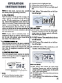
(B) Light Button: This controls the on / off function of the light.
c
B
A
D
"'fl
,{~;
:-~le8~1
(~}}~~M
nlustration2
060 and D80:
(A) JEIS button: This controls the main pump
functions. Depress once and the hi-speed jet
pump comes on, depress again, it will switch
NOTE: H your water is extremely hard, it is
back to low-speed pump.
preferable to fill the spa halfway with hard water
and the rest with softened water. Never fill the (8) BLOWER button: This controls the air blower
spa entirely with softened water.
on I off function.
il2) TU...N8
POWER ON
(q UGHT button: This controls the on/ off funcBefore turning the power to the spa on, rotate the
.tion of the light.
thermostat knob to the off position and place the
timer selection switch to the manual (up) posi- (D) AUXILIARY button: This controls the on/ off
tion. Oose the equipment accessdoor and turn
function of the auxiliary pump.
the power on.
c
3) FUNcn08
S.ELEcrION
Before activating the heater, depress the selection
buttons on the spa side control to engage the various functions as follows:
B
"",'!;:, ,c;;;'""":i\;c;',,
,c""",""-".%,
(
Dlustration
'
1
f
""
A
i r
015:
i
(A) This is a Selection function cOntrol.
1. Depress once for low speed jets.
D30 and D40:
A) JETS button: This controls the main pump
functions. Depress once and the hi-speed jet
pump comes on, depress again, it will switd\
back to low-speed pump.
(B) BLOWER button: This controls the air blower
on/ off function.
(C) UGHf button: This controls the on/ off function of the light.
[ZJ
4) HEATING YOUR SPA .
After engaging the various functions and returning to the low speed pump function, turn the thermostat knob to the hot position. The spa temperature will rise seven to ten degrees per hour.
When the desired temperature is reached, place
the timer selection switch to the center position
and set the time of day and the amount of run
time (seeTImer Operation).
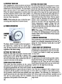
SETTING THE RUN nME
The outer ring of the timer is comprised of a series
of pins that will slide in ~oward the center or out
toward the edge of the timer. Each pin represent'.."J
fifteen minutes. When the pins are slid in towards ,
the center of the timer the low speed pump will
run. When they are slid to the outer edge the low
speed is off. The minimal amount of run time recommended per day is four hours. The low speed
pump is used for filtration and maintaining the
MOlE: While heating the spa, or when the spa is desired water temperature in your spa. The
not being used, keep the air controls closed.
amount of run time will vary depending on the
chosen temperature, supply voltage ~""\d the
external temperature. When selecting the run
5) nMER
OPERAnON
time, all the pins between the time selected must
be slid in towards the center.
i;.:!~.'\~
~'),~
,~*
C0881MT
~IMER
;.;,~
J(tC~,
-
OFF
J
£.:.~7~
mustration
4
NOTE: When using a vrrAZONE water purification system, the minimal amount of nm time will
increase. Refer to the vrrAZONE owners manual
for instructions.
6) FREEZE PROrECTION
Freeze protection is provided by setting the thermostat at an adequate temperature level and ~J
setting the Timer Selection Switch (ill. 2) to the
ON (up) position.
The timer, which is located on the front panel of
the control box, controls the low speed pump
only. All other functions of the spa are accessible 7) ADD START UP CHEMICALS
Carefully follow the directions and add the startregardless of the timer setting.
up chemicals recommended to you by your dealSEnING THE nME OF DAY
er. Contact your dealer .to clarify any questions
Rotate the outer ring of the timer clockwise until
you may have.
present time of day (AM/~)
is aligned with
time indicator arrow. NOTE: The center dial will
also turn as the outer ring is rotated and will correspond to the time of day setting.
8) LIGHT OPERATION
The light button is located on the spa side control.
Depress the button once for the light to come on
.and again to go off. There are two mood setting
TIMER sELECnON SWITCH
colored lenses included with your spa which may
This switch has three positions for the various be placed over the light lens in the spa.
operations of low speed. In the down position the
low speedis permanently off. In the center position 9) JET OPERATION
(I1MER MODE) the low speedwill turn on and off Your Vita Spa is designed with a unique jet sysas selectedwith the position of the timer pins. In tem to allow you to select a wide variety 0£ masthe up position, whi~.is used when initially heat- sage patterns. The £ollowing is a description 0£"'""I
ing the spa and also for cold climate freeze protec- the various types 0£ jets and their operation you /
tion, the low speed pump will run constantly may use to tailor your spa to your specific massage needs.
regardlessof the position of the timer pins.
00
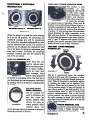
DIRECTIONAL & ROTATIONAL
MASSAGE JETS
opg
THREE-WAY
POWER DIVERTER VALVE
This feature is only
available
on
spas
equipped with the D80
or D60 series equipment (Romance, Elan,
Allure and Essence).
opg
l
.This
Dlustratlon 8.
Cl.08E
Cl.08E
T8UPr
JET
Dlustration
~
1W8APY
~
5
When the pump is on and the turbo massage
jet is in the off position, the directional and
rotational massage jets will be operational.
The water flow direction is adjustable byrotating the directional jet nozzle. The amount of
pressure can be adjusted by totating the outer
rim of the jet(s): clockwise for minimum pres"
sure, and counter clockwise for maximum
pressure.Pressure may also be varied by the
use of the air control.
EURO 200 MASSAGE JO
These Euro jets are
used in various models for various purposes, In cluster configu~
ration for back and
neck massage, they
Dlustration 6
deliver a firm pinpoint
jet stream of.massaging action. The Euro jet is
not directional, but can be p,:t'essurecontrolled
by rotating the face of the jet or adjusting the
air co trol.
ic
AIR A.D OUnR
RI.G CO8TROLS
The air controls are
used to introduce air
into the water jet
stream. Marked with
arrows for open or
mustration7
closed position, these
controls allow the
user to increase(open) jet pressure or decrease
(close) jet pressure as desired.
valve is functional when the primary,
two speed pump is operating. Water may be
diverted to two individual sections of jets or a
combined operation of both sections. By turning the valve to the left, water will be diverted
to section" A " jets giving them the maximum
output. Rotating the valve completely to the
right will give section "B" the maximum output and when its turned to the center position,
both" A" and "B" sections will operate simultaneously. (See specific spa spec sheet insert for
details on how to use 3-Way Diverter).
FOUR WAY TURBO MASSAGE
DIVERTER JET
~:"~
Dlustration 9
c.-.
:"~
This jet is operational when the auxiliary
pump is on (for spas with 2 pumps), or whenever the pump is activated (single pump systerns). Water is diverted to various jet regions
by rotating the outer rim to assorted clock
positions. When the jet is turned to the three
o'clock position, sector RA Rjets will operate. At
nine o'clock, sector RBRjets will function. At six
o'clock position, both RA Rand RBRsectors will
pelform simultaneously. And at the twelve
o'clock position, the water is routed through
the turbo massage jet itself. (See specific spa
spe~ sheet insert for details on how to use the
4-Way Turbo Diverter).
FINGER MASSAGE JETS
Located at various points in the spa.
Creates a Rfinger massageR action
when blower is turned on.
Dlustration 10
[!]
A. H the spa will not be used, drain it completely
following
THE SPA."the
. instructions on MDRAINING
Your VrrA SPA is manufactured with the highest
quality and most durable materials available. A B. If you intend to use the spa during the winte
spa care and maintenance program is recomkeep the spa warm and set the timer to bring
mended to increase your comfort, maintain the
the pump on at night and a couple hours durspa's reliability and protect your investment.
ing the day. It is recommended to set the timer
to FREEZE PROTECflON (See pg. 8) when
1. DRAIN.NO YOUR SPA
the temperature drops below ~ F. This will
Detergent residues from bathing suits as well as
keep the low-speed pump running 24 hours
soap film from your body may gradually accuper day and protect against potential freezing
mulate in the water. Foam inhibitors will supof pipes. Note that accidental freezing could
press the foam but will not remove the soap from
result due to prolonged power failures.
the water. Eventually, the soap build-up in the
water will concentrate enough to leave an 3. FILTER MAINTENANCE
unclean feeling on the user's skin, cause sudsing Vita Spas are designed with the most efficient top
and make the water impossible to clarify. loading filtration system in ,the industry. Filter
Depending on the amount of soap input, the spa maintenance is the most critical factor in keeping
water should last between two and three months. your spa water clean.
To drain your Spa:
A.
Turn
the power
off at the GFO
breaker.
To clean the filter:
(NOTE: Never run spa without filter)
A
B. Attach a garden hose to tl)e yellow hose bib
located under the filter housing inside the
equipment area, and route the outlet of the
hose to an appropriate draining area. The spa
will empty by gravity. Siphon or scoop out the
B.
balance of the water.
IMPORTANT: Spa water with a high sanitizer
level may harm plants and grass.
H you are draining your spa for the winter, ~
sure to fully drain water from the pipe by di&connecting the two unions at the gate valves.
Drain the water pump by ~moVing the pump
plug. Then reinstall the valves and pump
plug.
c.
Remove
the filter
and clean
as required.
D. Inspect the spa shell and ~~an as required.
Remove the cartridge and spray it with a garden hose. It will be necessaryto rotate the cartridge while spraying so as to thoroughlx
remove the debris lodged between the filte:J
pleats.
After allowing to dry, inspect the cartridge for
calcium deposit (scaling) or an oil film. Rapid
mineral build-up from ham water, or oil build
up from the use of oil-based water scent or
body oil may coat the filter cartridge. A filter
cleaner to soak the cartridge is available from
your vrrA SPA dealer and should be used as
part of your spa maintenance.
c. Use a rag to remove any debris at the bottom
of the filter housing. Replace the cartridge.
D. We recommend the use of a spare filter. This
way one can be soaking and cleaning while
you continue to enjoy the use of your spa.
11
~j!
E. Refi11the spa BEFORE restoring power to it.
2. WINTERIZING YOUR SPA
Your VITA SPA has been designed and engineered for year-round use in any climate.
~
4. REDWOOD CABINET MAINTENANCE
Your VilA SPA cabinet is made with a high quality redwood. It is factory stained and sealed.
Depending on the location and exposure of the,\
spa to the rain and sun, it is recommended to sea-l
the redwood cabinet once or twice a year with a
wood sealant. Vita's specially formulated redwood sealer is available at your VilA SPA dealer.
5. MARINE VINYL COVER
Your cover is manufactured from a durable
marine grade, U .v. resistant material. Even so,
l -1\onthly cleaning and periodic conditioning is
£ecommended to maintain its beauty. To clean
and condition the vinyl cover:
A
Lightly spray the cover with a garden hose to
rinse it and remove the debris.
Spa water maintenance
consists
of three
separate, easily developed programs:
1. Sanitizing and maintaining a safe level of sanitizer in the spa water.
2. Balancing the pH and maintaining the recommended mineral content level.
3. Achieving and maintaining water clarity.
B. Using a large sponge or soft cloth and a mild SANITIZING
soap solution (1 teaspoon dish washing liquid To destroy bacteria and organic compounds in the
with 2 gallons of water), scrub lightly in circu- spa water, a sanitizer must be used regularly. The
.lar motion. Then rinse it thoroughly with use of a bromine floater is recommended. By regulating the amount of tablets, the amount the
plenty of water.
floater is open, and the length of the filtration
cycles, you can control the amount of bromine in
C. Condition the vinyl after cleaning by applying
your spa. A bromine residual of 2 to 3 ppm is gena thin film of vinyl conditioner
such as
erally considered desirable. A two-part bromine
ArmorAll. NOTE: To remove tree saps, use
system or granular chlorine (dichlor) are also
lighter fluid (not charcoal lighter but the kind
acceptable sanitizers.
used in cigarette lighters). Use sparingly and
rinse with mild soap solution afterwards.
."Wipe dry.
-
GENERAl GUIOnlNES
FOR WATER
QUALITY MAINTENANCE
Maintaining water quality within specific limits
will enhanceyour enjoyment and prolong the life
of the spa. Safe, comfortable and clean spa water
is a fairly simple task to achieve, but it does
require regular attention becauseof the numerous
factors that can alter it. There is no one formula to
be followed because of the variables, i.e. quality
of the water used to fill the spa, water temperature, user load, etc. For specific guidelines for
water quality maintenance, consult your VITA
SPA dealer who can assist you to develop a program based on your specific nee~. Disregard for
tL water maintenance wift.result in poor soaking
.conditions, damage your spa investment and possibly void your warranty.
pIt CONTROL
pH is a measure of acidity and alkalinity of the
spa water. The recommended pH for spa water is
7.4 to 7.6 ppm. Below 7.0 ( considered neutral), the
spa water is acidic and can cause damage to the
heating system. Above 7.8 the water is too alkaline and can result in cloudy water and scale formation on the spa shell, heater and cover.
IMPORTA.T:
.EVER
USE
CHLORI.E
TABLETS (TRICHLOR) I. YOUR SPA.
This chemical can have an extremely corrosive
effect on certain materials in the spa. Also, the use
of liquids, chlorine or acid, are not recommended.
Damage caused by use of these chemicals, or
improper use of any chemical, is not covered
under the spa warranty.
OPTIONAL VITAZONE WATER
PURIFlCAnON
a.aliM
If you have elected to equip your spa with the
optional vrrAZoNE
ozone water purification
system, you will find that your water stays fresh
and clean with significantly less usage of chemical sanitizer and you will also be able to go longer
between spa draining. Read and follow the
instructions
included with your VITAZONE
ozone water purification
system to determine
how to adjust your chemical usage and filter
cycles.
[!!]
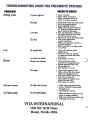
PROBLEM
AREAS TO CHECK
Nothing works
If power
light
on
No heat
Low heat
Too hot
Leak
~'
By equipment
Loc~tion not visible
Blower not working
Blower
High speedpump
.O1eck circuitry
.Reset "GFO" red button
.Make sure that timer is in
center or bottom position
.O\eck that valves are pulled open
.Turn thermostat knob up
.Reset high];clI1it switch
~ Make sure that timer switch is
on "Bottom" J?Osition and low
speed ~p
18operating
.Turn up thermostat clockwise
.Set longer hours on your time
and let run for 24 hours
.O\eck that valves are pulled open
.Turn down thermostat
counter clockwiSe
.Make sure that timer switcl\ is
in center position
.Make sure that jet or high speed
is not "Onw
.Check all 3 unions (hand
tighten only)
.C!leck for cracks at unions if cracks are found call dealer
for service
.Call dealer for service
.O\eck if blower cord is
connected to equipment pak
.Switch selection biltton till
blower li~
on
..Call dealer for service
No light
.O\eck bulb; replace if bad
.Make sure air fine from push
button to equipment is on
.Push light switm button one
time on, one time off
.Check GFO; if tripped, reset
(Elan 220 volts only)
.tall
dealer for service
;
No high speedpump
.Oteck valves are ~ulled open
.Switch "Selection button until
". t" 1i~t is on
."tall
No low speedpump
Low Speed pump
VITA
INTERNATIONAL
2320 NW 147th Street
Miami, Florida 33054
r"""
.-J
dealer for service
.Make sure timer switch is on the
center or bottom position
.Make sure valves are pulled open
.Call dealer for service
-"'