1
EZ-ZONE™ PM
Controller Communications
Manual
TOTAL
CUST
CUS
TOMER
SATISF
TISFA
ACTI
CTIO
ON
3 Year Warranty
ISO 9001
Registered Company
Winona, Minnesota USA
1241 Bundy Boulevard., Winona, Minnesota USA 55987
Phone: +1 (507) 454-5300, Fax: +1 (507) 452-4507 http://www.watlow.com
0600-0056-0000 Rev. B
November 2007
Made in the U.S.A.
$15.00
Safety Information
• Complete model number
We use note, caution and warning symbols throughout this book to draw your attention to important
operational and safety information.
• All configuration information
A “NOTE” marks a short message to alert you to
an important detail.
A “CAUTION” safety alert appears with information that is important for protecting your equipment and performance. Be especially careful to
read and follow all cautions that apply to your
application.
A “WARNING” safety alert appears with information that is important for protecting you, others and equipment from damage. Pay very close
attention to all warnings that apply to your
application.
The safety alert symbol, ç (an exclamation
point in a triangle) precedes a general CAUTION
or WARNING statement.
The electrical hazard symbol, Ó (a lightning bolt
in a triangle) precedes an electric shock hazard
CAUTION or WARNING safety statement.
ç
Ó
• User’s Manual
• Factory Page
Return Material Authorization (RMA)
1. Call Watlow Customer Service, (507) 454-5300,
for a Return Material Authorization (RMA) number before returning any item for repair. If you
do not know why the product failed, contact an
Application Engineer or Product Manager. All
RMA’s require:
• Ship-to address
• Bill-to address
• Contact name
• Phone number
• Method of return shipment
• Your P.O. number
• Detailed description of the problem
• Any special instructions
• Name and phone number of person returning
the product.
CAUTION or WARNING
Electrical Shock Hazard
CAUTION or WARNING
Warranty
The EZ-ZONE™ PM is manufactured by ISO 9001registered processes and is backed by a three-year
warranty to the first purchaser for use, providing
that the units have not been misapplied. Since Watlow has no control over their use, and sometimes
misuse, we cannot guarantee against failure. Watlow’s obligations hereunder, at Watlow’s option, are
limited to replacement, repair or refund of purchase
price, and parts which upon examination prove to be
defective within the warranty period specified. This
warranty does not apply to damage resulting from
transportation, alteration, misuse or abuse. The purchaser must use Watlow parts to maintain all listed
ratings.
Technical Assistance
If you encounter a problem with your Watlow controller, review your configuration information to verify
that your selections are consistent with your application: inputs, outputs, alarms, limits, etc. If the problem persists, you can get technical assistance from
your local Watlow representative (see back cover), by
e-mailing your questions to wintechsupport@watlow.
com or by dialing +1 (507) 494-5656 between 7 a.m.
and 5 p.m., Central Standard Time (CST). Ask for for
an Applications Engineer. Please have the following
information available when calling:
2. Prior approval and an RMA number from the
Customer Service Department is required when
returning any product for credit, repair or evaluation. Make sure the RMA number is on the outside of the carton and on all paperwork returned.
Ship on a Freight Prepaid basis.
3. After we receive your return, we will examine it
and try to verify the reason for returning it.
4. In cases of manufacturing defect, we will enter a
repair order, replacement order or issue credit for
material returned. In cases of customer mis-use,
we will provide repair costs and request a purchase order to proceed with the repair work.
5.
To return products that are not defective, goods
must be be in new condition, in the original boxes
and they must be returned within 120 days of
receipt. A 20 percent restocking charge is applied
for all returned stock controls and accessories.
6. If the unit is unrepairable, you will receive a
letter of explanation. and be given the option to
have the unit returned to you at your expense or
to have us scrap the unit.
7. Watlow reserves the right to charge for no trouble found (NTF) returns.
The EZ-ZONE™ PM User’s Manual is copyrighted by
Watlow Winona, Inc., © March 2007 with all rights
reserved.
EZ-ZONE™ PM is covered by U.S. Patent No.
6,005,577 and Patents Pending
Table of Contents
Chapter 1 PM Communications . . . . . . . . . . . . . . . . . . . . . . . . . . . . . .3
EZ-ZONE™ PM & Communications . . . . . . . . . . . . . . . . . . . . . . . . . . . . 3
Protocols . . . . . . . . . . . . . . . . . . . . . . . . . . . . . . . . . . . . . . . . . . . . . . . . 3
Chapter 2 Modbus RTU & TCP. . . . . . . . . . . . . . . . . . . . . . . . . . . . . . .4
Modbus Remote Terminal Unit (RTU) and Modbus TCP . . . . . . . . . . . . 4
Default PM Communication Parameters (Modbus RTU) . . . . . . . . . . . . 4
User Programmable Memory Blocks . . . . . . . . . . . . . . . . . . . . . . . . . . . 5
Using a MicroLogix 1200 PLC as the Master - Configuration . . . . . . . . 7
Reading & Writing 32-Bit PM Parameters . . . . . . . . . . . . . . . . . . . . . . 12
Communications Using Modbus TCP Over Ethernet . . . . . . . . . . . . . . 15
Configuring the PM for Modbus TCP Communications . . . . . . . . . . . . 15
Configuring Modbus TCP Communications with KepserverEX . . . . . . . 16
Chapter 3 EtherNet/IP . . . . . . . . . . . . . . . . . . . . . . . . . . . . . . . . . . . 29
Introduction to EtherNet/IP . . . . . . . . . . . . . . . . . . . . . . . . . . . . . . . . . . 29
PM Connectivity over EtherNet/IP . . . . . . . . . . . . . . . . . . . . . . . . . . . . 29
I/O Configuration using an Allen-Bradley Logix Family Processor . . . . 31
Saving Settings to Non-volatile Memory . . . . . . . . . . . . . . . . . . . . . . . 39
Chapter 4 DeviceNet . . . . . . . . . . . . . . . . . . . . . . . . . . . . . . . . . . . . 40
Introduction to DeviceNet . . . . . . . . . . . . . . . . . . . . . . . . . . . . . . . . . . . 40
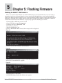
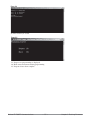
Chapter 5: Flashing Firmware . . . . . . . . . . . . . . . . . . . . . . . . . . . . . . 54
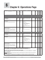
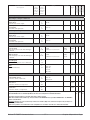
Chapter 6: Operations Page . . . . . . . . . . . . . . . . . . . . . . . . . . . . . . . 56
Chapter 7: Setup Page . . . . . . . . . . . . . . . . . . . . . . . . . . . . . . . . . . . 67
Chapter 8: Profiling Page . . . . . . . . . . . . . . . . . . . . . . . . . . . . . . . . . 87
Chapter 9: Factory Page . . . . . . . . . . . . . . . . . . . . . . . . . . . . . . . . . 133
Watlow EZ-ZONE™ Modbus Communications
•
1 •
Table of Contents
Watlow EZ-ZONE™ Modbus Communications
•
2 •
Table of Contents
1
Chapter 1 PM Communications
EZ-ZONE™ PM & Communications
With the introduction of the first Programmable Logic Controllers (PLCs) in the early to mid 1970s it
quickly became apparent that there was a need to communicate between one PLC and another, and then on
a wider scale, between PLCs and other computers within the company infrastructure. Some of those needs
involved applications with interlinking processes, such as batch processes or assembly lines utilizing multiple
controls that required better synchronization and control.
Over time the scope of the requirements for industrial communications broadened and became better defined, with specific needs being addressed. Those requirements and specifications centered on collecting data,
configuring controls, and controlling a process.
Protocols
Protocol describes how to exchange data. It also prevents two machines from attempting to send data at
the same time. There are a number of different data communications protocols in use today. The protocol part
of Watlow communications is very important, because it gives us a quality of communication that others often
don’t have. The EZ-ZONE™ PM family of controls provides several different protocols (Modbus RTU & TCP,
EtherNet/IP, and DeviceNet) meeting today's communication needs across many industrial applications.
In information technology, a protocol is the special set of rules that end points in a telecommunication
connection use when they communicate. Protocols exist at several levels in a telecommunication connection.
For example, there are protocols for the data interchange at the hardware device level and protocols for data
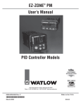
interchange at the application program level. In the standard model known as Open Systems Interconnection (OSI), there are one or more protocols at each layer in the telecommunication exchange that both ends
of the exchange must recognize and observe. Virtually all networks in use today are based in some fashion on
the OSI standard. OSI was developed in 1984 by the International Organization for Standardization (ISO),
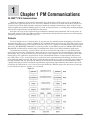
a global federation of national standards organizations representing approximately 130 countries. As can be
seen below the OSI model is a set of seven layers that define the different stages that data must go through
to travel from one device to another over a network.
Figure 1.1
Watlow EZ-ZONE™ Communications
•
3
•
Chapter 1
2
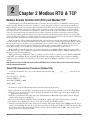
Chapter 2 Modbus RTU & TCP
Modbus Remote Terminal Unit (RTU) and Modbus TCP
Gould Modicon, now called AEG Schneider, created the protocol refered to as "Modbus" used in process
control systems. Modbus provides the advantage of being extremely reliable in exchanging information, a
highly desirable feature for industrial data communications. This protocol works on the principle of packet
exchanges. The packet contains the address of the controller to receive the information, a command field
that says what is to be done with the information, and several fields of data. Reading from these registers
retrieves all information in the controller. Each of these registers are listed in this user’s manual (Operations, Setup, Profiling, & Factory Pages). You will need this list to determine where the data is located. The
last item sent in the packet is a field to ensure the data is received intact. This is called a cyclical redundancy
check-sum (CRC). All information exchanged is in hexadecimal numbers.
Many parameter values within the PM controller are four bytes in length and require two Modbus registers. By default, the low register number contains the two lower bytes and the high register number contains
the two higher bytes. If it makes your programming easier you may reverse this Modbus default where the
low register number contains the two higher bytes and the high register number contains the two lower
bytes. This setting can be modified in the PM controller Setup pages under the "Com" menu.
Modbus RTU is typically deployed over serial connections where Modbus TCP is deployed over the Ethernet physical layer. If it is desired to acquire more information on Modbus RTU or Modbus TCP direct your
browser to: http://www.modbus.org.
When purchasing a third-party software package, be sure to look for a package that is Modbus RTU/TCP
compatible or has Modbus drivers included. Most third-party packages require you to specify the Modbus
registers of the controller to setup and use the package. Again, all Modbus addresses can be found in this
manual.
Note: Excessive writes to the PM may cause premature EEPROM failure. For more detail see the section entitled "Saving
Settings to Nonvolatile Memory".
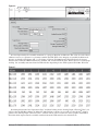
Default PM Communication Parameters (Modbus RTU)
If your model number has a one in the identified placeholder (PM_ _ _ _ _- [1] _ _ _ _ _ _) then these defaults apply.
Protocol ([PCoL]) = Modbus
Address ([Ad;M]) = 1
Baud Rate ( [bAUd]) = 9600
Parity ([PAr]) = none
To change or view the PM communication defaults follow the steps below:
1. Push and hold the up and down arrow keys on the front panel for six seconds to go the the Setup Menu.
2. Push the up or down arrow key until [`CoM] (Communications Menu) appears in upper display and
[`SEt] in the lower display.
3. Push the green Advance Key ‰ to enter the Communications Menu. The upper display shows [Mod],
and the lower display shows [PCoL].
4. Push the green Advance Key ‰ to change the Modbus address. The upper display shows [1], and the
lower display shows [Ad;M]. Use the up arrow key to change the Modbus address.
5. Push the green Advance Key ‰ to change the baud rate. The upper display shows [9600], and the lower
display shows [bAUd]. Use the up and or down arrow key to change the baud rate. Push the Advance Key
‰ to change parity. The upper display shows [nonE] and lower display shows [PAr]. Use the up and or
down arrow key to change the parity.
Watlow EZ-ZONE™ Communications
•
4
•
Chapter 2 Mobbus RTU & TCP
If your model number has a two in the identified placeholder (PM_ _ _ _ _- [2] _ _ _ _ _ _) then these defaults apply.
Port 1 = Standard Bus
Port 2
Address ([Ad;S]) = 1
Protocol ([PCoL]) = Modbus
Address ([Ad;M]) = 1
Baud Rate ( [bAUd]) = 9600
Parity ([PAr]) = none
When two ports are available as the above part number indicates, port one will always be Standard bus
with no option to change. Standard bus is used to interface with Watlow's EZ-ZONETM configuration software
and is also used when a controllers firmware is flashed to a new revision. The key strokes to view and change
these parameters differs slightly from the above example due to the additional port. See below:
To change or view the PM communication defaults follow the steps below:
1. Push and hold the up and down arrow keys on the front panel for six seconds to go the the Setup Menu.
2. Push the up or down arrow key until [`CoM] (Communications Menu) appears in upper display and
[`SEt] in the lower display.
3. Push the green Advance Key ‰ to select port one or two. The upper display shows [1], and the lower display shows [CoM]. Use the up arrow key to change the port number and then push the green advance
button to proceed.
4. If you pushed one above (for port 1) the top display will indicate the Standard bus address [1], and the
lower display will show [Ad;S]. Use the up arrow key to change the Standard bus address.
If you pushed two above (for port 2) in step three the keystrokes defined above for option 1 beginning at
step four would then apply.
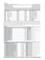
User Programmable Memory Blocks
EZ-ZONE™ PM models equipped with the Modbus protocol (PM_ _ _ _ _- [1, 2, or 3] _ _ _ _ _ _) features
a block of addresses that can be configured by the user to provide direct access to a list of 40 user configured
parameters. This allows the user easy access to this customized list by reading from or writing to a contiguous
block of registers.
In an attempt to make this concept easier to understand it would be best to define the column headers below before we go further.
Assembly Definition Addresses - Fixed addresses used to define the parameter that will be stored in the
"Working Addresses". May also be referred to as a pointer. The value
stored in these addresses will reflect (point to) the Modbus address of a
parameter within the PM control.
Assembly Working Addresses - Fixed addresses directly related to their associated "Assembly Definition
Addresses" (i.e., working addresses 200 & 201 will assume the parameter
pointed to by definition addresses 40 & 41) used in the main body of
your user program to read from or write to a factory default parameter
or a user configured parameter.
So, when the Modbus address of a target parameter is stored in an "Assembly Definition Address" its corresponding working address will return that parameter’s actual value. If it’s a writable parameter, writing to its
working register will change the parameter’s actual value. The list below reflects the Assembly Definition Addresses as well as their associated Assembly Working Addresses.
Watlow EZ-ZONE™ Communications
•
5
•
Chapter 2 Mobbus RTU & TCP
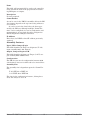
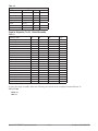
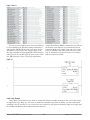
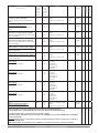
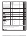
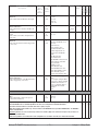
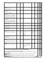
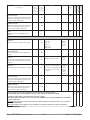
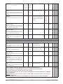
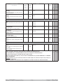
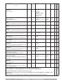
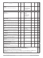
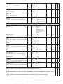
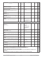
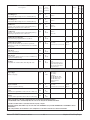
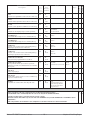
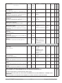
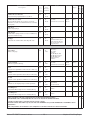
Table 2.0: Assembly Definition Addresses and Assembly Working Addresses
Assembly Definition
Addresses
40 & 41
42 & 43
44 & 45
46 & 47
48 & 49
50 & 51
52 & 53
54 & 55
56 & 57
58 & 59
60 & 61
62 & 63
64 & 65
66 & 67
68 & 69
70 & 71
72 & 73
74 & 75
76 & 77
78 & 79
Assembly Working
Addresses
200 & 201
202 & 203
204 & 205
206 & 207
208 & 209
210 & 211
212 & 213
214 & 215
216 & 217
218 & 219
220 & 221
222 & 223
224 & 225
226 & 227
228 & 229
230 & 231
232 & 233
234 & 235
236 & 237
238 & 239
Assembly Definition
Addresses
80 & 81
82 & 83
84 & 85
86 & 87
88 & 89
90 & 91
92 & 93
94 & 95
96 & 97
98 & 99
100 & 101
102 & 103
104 & 105
106 & 107
108 & 109
110 & 111
112 & 113
114 & 115
116 & 117
118 & 119
Assembly Working
Addresses
240 & 241
242 & 243
244 & 245
246 & 247
248 & 249
250 & 251
252 & 253
254 & 255
256 & 257
256 & 259
260 & 261
262 & 263
264 & 265
266 & 267
268 & 269
270 & 271
272 & 273
274 & 275
276 & 277
278 & 279
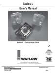
As an example, Modbus register 360 contains the Analog Input 1 Process Value (See Operations Page,
Analog Input Menu). If the value 360 is loaded into Assembly Definition Address 91, then the process value
sensed by input 1 will also be stored in Modbus registers 250 and 251.
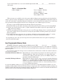
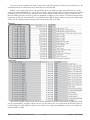
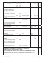
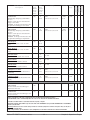
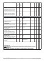
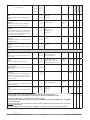
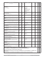
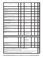
In figure 2.0 & 2.1 below we can see a different view of the Assembly Definition and Working Addresses
along with the factory defaults for the assembly.
Figure 2.0 & 2.1 Default Assembly Structure
Assembly Definition
Addresses
Default Pointers
Registers 40 & 41
Assembly Working
Addresses
Assembly Definition
Addresses
Default Pointers
Assembly Working
Addresses
Registers 200 & 201
Registers 60 & 61
Registers 220 & 221
Pointer 1 = 1880 & 1881
Loop Control Mode
Registers 42 & 43
Value of Pointer 1
Pointer 10 = 1630 & 1631
Alarm 4 High Set Point
Pointer 15 = 1892 & 1893
Cool Proportional Band
Value of Pointer 5
Registers 70 & 71
Registers 210 & 211
Pointer 16 = 1894 & 1895
Time Integral
Value of Pointer 6
Registers 72 & 73
Registers 212 & 213
Pointer 17 = 1896 & 1897
Time Derivative
Value of Pointer 7
Registers 74 & 75
Registers 214 & 215
Pointer 18 = 1900 & 1901
Heat Hysteresis
Value of Pointer 8
Registers 76 & 77
Registers 216 & 217
Pointer 9 = 1582 & 1583
Alarm 3 Low Set Point
Registers 58 & 59
Registers 68 & 69
Registers 208 & 209
Pointer 8 = 1580 & 1581
Alarm 3 High Set Point
Registers 56 & 57
Pointer 14 = 1890 & 1891
Heat Proportional Band
Value of Pointer 4
Pointer 7 = 1532 & 1533
Alarm 2 Low Set Point
Registers 54 & 55
Registers 66 & 67
Registers 206 & 207
Pointer 6 = 1530 & 1531
Alarm 2 High Set Point
Registers 52 & 53
Pointer 13 = 2520 & 2521
Profile Start
Value of Pointer 3
Pointer 5 = 1482 & 1483
Alarm 1 Low Set Point
Registers 50 & 51
Registers 64 & 65
Registers 204 & 205
Pointer 4 = 1480 & 1481
Alarm 1 High Set Point
Registers 48 & 49
Pointer 12 = 2540 & 2541
Profile Action Request
Value of Pointer 2
Pointer 3 = 2162 & 2163
Open Loop Set Point
Registers 46 & 47
Registers 62 & 63
Registers 202 & 203
Pointer 2 = 2160 & 2161
Closed Loop Set Point
Registers 44 & 45
Pointer 11 = 1632 & 1633
Alarm 4 Low Set Point
Pointer 19 = 1902 & 1903
Cool Hysteresis
Value of Pointer 9
Registers 78 & 79
Registers 218 & 219
Pointer 20 = 1898 & 1899
Deadband
Value of Pointer 10
Watlow EZ-ZONE™ Communications
•
6
•
Value of Pointer 11
Registers 222 & 223
Value of Pointer 12
Registers 224 & 225
Value of Pointer 13
Registers 226 & 227
Value of Pointer 14
Registers 228 & 229
Value of Pointer 15
Registers 230 & 231
Value of Pointer 16
Registers 232 & 233
Value of Pointer 17
Registers 234 & 235
Value of Pointer 18
Registers 236 & 237
Value of Pointer 19
Registers 238 & 239
Value of Pointer 20
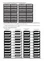
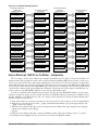
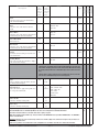
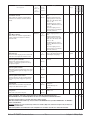
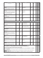
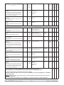
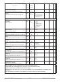
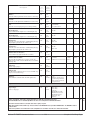
Chapter 2 Mobbus RTU & TCP
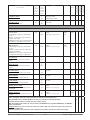
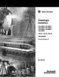
Figure 2.2 & 2.3 Default Assembly Structure
Assembly Definition
Addresses
Default Pointers
Assembly Working
Addresses
Registers 80 & 81
Registers 240 & 241
Pointer 21 = 360 & 361
Analog Input 1 Process
Value
Registers 82 & 83
Registers 84 & 85
Registers 242 & 243
Registers 86 & 87
Registers 88 & 89
Registers 90 & 91
Registers 108 & 109
Pointer 35 = 2520 & 2521
Profile Start
Value of Pointer 25
Registers 250 & 251
Registers 110 & 111
Pointer 36 = 2540 & 2541
Profile Action Request
Value of Pointer 26
Registers 252 & 253
Registers 112 & 113
Pointer 37 = 2524 & 2525
Active File
Value of Pointer 27
Registers 254 & 256
Registers 114 & 115
Pointer 38 = 2526 & 2527
Active Step
Value of Pointer 28
Registers 256 & 257
Pointer 29 = 1328 & 1329
Digital Input 5 Status
Registers 98 & 99
Pointer 34 = 690 & 691
Limit State
Registers 248 & 249
Pointer 28 = 1646 & 1647
Alarm 4 State
Registers 96 & 97
Registers 106 & 107
Value of Pointer 24
Pointer 27 = 1596 & 1597
Alarm 3 State
Registers 94 & 95
Pointer 33 = 1906 & 1907
Cool Power
Registers 246 & 247
Pointer 26 = 1546 & 1547
Alarm 2 State
Registers 92 & 93
Registers 104 & 105
Value of Pointer 23
Pointer 25 = 1496 & 1497
Alarm 1 State
Registers 116 & 117
Pointer 39 = 2528 & 2529
Active Set Point
Value of Pointer 29
Registers 258 & 259
Pointer 30 = 1348 & 1349
Digital Input 6 Status
Registers 260 & 261
Pointer 32 = 1904 & 1905
Heat Power
Registers 244 & 245
Pointer 24 = 442 & 443
Analog Input 2 Error Status
Registers 100 & 101
Registers 102 & 103
Value of Pointer 22
Pointer 23 = 440 & 441
Analog Input 2 Process
Value
Assembly Working
Registers
Pointer 31 = 1882 & 1883
Control Mode Active
Value of Pointer 21
Pointer 22 = 362 & 363
Analog Input 1 Error Status
Assembly Definition
Registers
Default Pointers
Registers 118 & 119
Pointer 40 = 2536 & 2537
Step Time Remaining
Value of Pointer 30
Value of Pointer 31
Registers 262 & 263
Value of Pointer 32
Registers 264 & 265
Value of Pointer 33
Registers 266 & 267
Value of Pointer 34
Registers 268 & 269
Value of Pointer 35
Registers 270 & 271
Value of Pointer 36
Registers 272 & 273
Value of Pointer 37
Registers 274 & 275
Value of Pointer 38
Registers 276 & 277
Value of Pointer 39
Registers 278 & 279
Value of Pointer 40
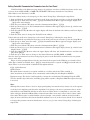
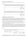
Using a MicroLogix 1200 PLC as the Master - Configuration
Prior to taking a look at some ladder logic examples provided below let’s take a look at the hardware configuration first. This particular control can be purchased with the Modbus RTU protocol and as can be seen
in the screen shots that follow, channel 0 is configured as such. Please note that the hardware configuration
will be different from one control to another. The following screen shots apply to the MicroLogix 1200 control
only. Using the Allen-Bradley 1761-CBL-PM02 cable connecting it to channel 0 of the PLC it is required that
a null modem adapter along with an EIA-232 to EIA-485 converter be used. The output of the EIA-485 converter connects to the EZ-ZONE™ PM slot C (A to CA, B to CB, GND to CC).
In order to establish valid communications between the PLC and the EZ-ZONE™ PM the serial communications parameters need to match on both ends, PLC and PM. The PM can communicate at 9.6Kb (factory
default), 19.2Kb, or 38.4 Kb with even, odd, or no parity (factory default). To change the PM communication
defaults follow the steps below:
1. Push and hold the up and down arrow keys on the front panel for six seconds to go the the Setup Menu.
2. Push the up or down arrow key until [`CoM] (Communications Menu) appears in upper display and
[`SEt] in the lower display.
3. Push the green Advance Key ‰ to enter the Communications Menu. The upper display shows [Mod],
and the lower display shows [PCoL].
[`CoM].
4. Push the green Advance Key ‰ to change the Modbus address. The upper display shows [1], and the
lower display shows [Ad;M]. Use the up arrow key to change the Modbus address.
Watlow EZ-ZONE™ Communications
•
7
•
Chapter 2 Mobbus RTU & TCP
5. Push the green Advance Key ‰ to change the baud rate. The upper display shows [9600], and the lower
display shows [bAUd]. Use the up and or down arrow key to change the baud rate.
6. Push the Advance Key ‰ to change parity. The upper display shows [nonE] and lower display shows
[PAr]. Use the up and or down arrow key to change the parity.
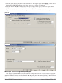
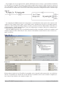
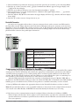
Figure 2.4 and 2.5 below capture the settings for channel 0 from the PLC used for this example.
Figure 2.4
Figure 2.5
MicroLogix 1200 PLC Programming Examples
Now that we’ve addressed the hardware side of the configuration let’s take a closer look at the programming in the PLC. In the first example below, the message instruction is simply reading back the Assembly
Definition Addresses (factory defaults) from the PM and placing them in a table beginning at N11:100 in the
PLC.
Watlow EZ-ZONE™ Communications
•
8
•
Chapter 2 Mobbus RTU & TCP
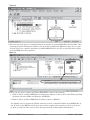
Figure 2.6
As stated previously, the assembly structure is a group of 40 pairs of addresses. The value in each of these
addresses serves as a pointer to a parameter within the PM. Each of the 40 pairs of assembly definition addresses are displayed in figures 2.0 - 2.3. In figure 2.7 below, N11:100 through N11:179 shows the factory
default values after the MSG instruction is enabled and executed without error. Notice this is a read message
reading the assembly structure from the PM and then depositing it into PLC registers N11:100 - N11:179.
Figure 2.7
Searching this manual for “Operations Page” and then looking for the “Analog Input 1 Process Value” you
will see that the Modbus address is defined as 360. Looking at figure 2.2 you will see that the 21st pointer
points to the “Analog Input 1 Process Value” and this can be seen as well in the above graphic (N11:140 &
N11:141) which represents the assembly read-back from the PM control in the default state.
Watlow EZ-ZONE™ Communications
•
9
•
Chapter 2 Mobbus RTU & TCP
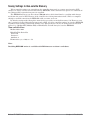
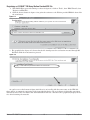
In the example logic below a message instruction is configured to write a new parameter to the first member of the Assembly Definition Addresses.
Figure 2.8
Because each of the assembly definition addresses and working registers are 32-bits it is necessary to set
this instruction to write to multiple registers, in this case 2. Within figure 2.8 we see an inset image that
reflects what is being written to the PM (N11:12 = 1328 and N11:13 = 0). When the MSG instruction is executed it will redefine the nineteenth assembly parameter of the PM as Digital Input 5 State . The logic shown
above can be used to change any of the assembly member definitions simply by changing the value of N11:12
to the desired parameter and then the MB Assembly Definition Address (pointer) to the desired member.
Figure 2.9
So, looking at figure 2.9 we can see that if a MSG instruction is configured to read register 40237 that it will
now contain the current state of digital input 5 (DI5). After the MSG instruction is executed we see that DI5
is currently in the Active state (5). As was the case in the previous example, the logic shown above can be easily changed to read or write any of the configured parameters simply by changing the data table address and
the MB data address to the desired values.
Watlow EZ-ZONE™ Communications
•
10
•
Chapter 2 Mobbus RTU & TCP
Lastly, the logic example below will read the process value (40361 and 40360) in from the PM and place it in
N11:0 and N11:1. The copy word instruction that follows will then simply deposit what's in N11:0 and N11:1
into floating point address F8:0 (inset graphic in figure 2.11) where we see the current temperature is ~275
o
Figure 2.10
Figure 2.11
Watlow EZ-ZONE™ Communications
•
11
•
Chapter 2 Mobbus RTU & TCP
Reading & Writing 32-Bit PM Parameters
The process value of the EZ-ZONE™ PM is contained in two 16-bit registers. Register 360 contains the
two lower bytes (least significant word, LSW) while register 361 contains the two higher bytes (most significant word, MSW). The 32-bit answer is an IEEE 754, 32-bit float data type.
As an example:
977D 429C is in Low Word – High Word Order. Changing to High Word – Low Word, the value is 429C 977D.
429C977D = 78.20407867 degrees when read as a 32-bit float
To read a 32-bit value, perform the following:
Assemble a packet (examples follow below) to send the controller based on these steps:
1. Determine controller address to read. Example: Address 1
2. Determine function code for read. Example: Function Code 3 hexadecimal for read holding register
3. Determine relative Modbus registers to read (360 & 361 decimal for Analog Input 1)
4. Convert register numbers to Hexadecimal. Example: 360 decimal = 168 hexadecimal
5. Enter 0 for number of registers to read high byte
6. Determine number of registers to read. Example: 2 registers to retrieve a 32-bit value
7. Enter number of registers to read low byte from previous step into packet.
8. Calculate the CRC on the packet.
9. Enter the Low Byte of CRC calculation into packet
10. Enter the High Byte of CRC calculation into packet
11. Send packet as one continuous stream
12. Wait for response from controller
Process the packet received based on these steps:
1. Process packet for accuracy by comparing CRC to calculated value
2. Parse answer from packet based on number of bytes returned
3. Convert answers to appropriate data type
To acquire more information on the Modbus packet layout direct your browser to: http://www.modbus.org.
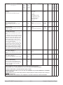
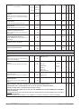
Table 2.1
Binary
Hex Decimal
Purpose
00000001 01
1
Controller Address
00000011 03
3
Function Read
00000001 01
1
Read Starting at Register High Byte (AIN 1 Process is Register 360 & 361)
01101000 68
104
Read Starting at Register Low Byte (AIN 1 Process is Register 360 & 361)
00000000 00
0
Read number of consecutive registers - High Byte (Always 0)
00000010 02
2
Read number of consecutive registers - Low Byte
10000100 44
68
Low byte of CRC
00101011 2B
43
High byte of CRC
The CRC (also a 16-bit wide value) is sent in reverse order, low byte then high byte.
Watlow EZ-ZONE™ Communications
•
12
•
Chapter 2 Mobbus RTU & TCP
o
Table 2.2
Binary
Received from the Read Analog Input 1 Process Value 78.204 F (32-bit)
Hex Decimal
Purpose
00000001
01
1
Controller Address
00000011
03
3
Function Read
00000100
04
4
Number of data bytes returned
10010111
97
151
Data High Byte of 1st register Read - MSB of LSW
01111101
01000010
7D
42
125
Data Low Byte of
66
1st
register Read - LSB of LSW
consecutive registers
consecutive registers
Data High Byte of
2nd
register Read - MSB of LSW
consecutive registers
2nd
register Read - LSB of MSW
consecutive registers
10011100
9C
156
Data Low Byte of
01110110
76
118
Low byte of CRC
10010110
96
150
High byte of CRC
Some process values may be rounded off to fit into the four-character display of the EZ-ZONE™ PM, depending on the Decimal setting in the Global, Setup menu.
To change the Decimal setting via communications, write a 105 for whole units (0) display, 94 for tenths (0.0)
display, 40 for hundredths (0.00) display or 96 for thousands (0.000) display to unsigned integer 16-bit register 398 for analog input 1 or register 478 for analog input 2. This setting has no impact on the values read via
communications. Full process values are readable via Modbus. The displayed units of measurement are independent of the units of measurement sent via communications. As an example:
The controller may be set to display in °C on the LED but utilize °F in communication sent values.
- All temperature parameters are in °F through Modbus by default.
To change communications temperature units via Modbus, write a 30 for °F or 15 for °C to unsigned integer
16-bit register 2490 for analog input 1 and register 2510 for analog input 2. (Requires firmware version 2.0 or
newer).
Example: To write a 32-bit value in decimal format.
Note: The closed loop set point of the EZ-ZONE™ PM is contained in two 16-bit registers. Register 2160
contains the two lower bytes (least significant word, LSW) while register 2161 contains the two higher bytes
(most significant word, MSW). The 32-bit answer is an IEEE 754, 32-bit float data type.
42960000 = 75.0 degrees when read as a 32-bit float
0000 4296 is in Low Word, High Word Order.
Register 2160 is written with LSW of 0000 hexadecimal
Register 2161 is written with MSW of 4296 hexadecimal
Table 2.3
Binary
Sent to Write (32-bit) Closed Loop Set Point of 75.0 oF
Hex Decimal
Purpose
00000001
01
1
Controller Address
00010000
10
16
Function Multiple Write
00001000
08
8
Write Starting at Register High Byte (CLSP is Register 2160 & 2161)
01110000
70
112
Write Starting at Register Low Byte (CLSP is Register 2160 & 2161)
00000000
00
0
Write number of consecutive registers - High Byte (Always 0)
00000010
02
2
Write number of consecutive registers - Low Byte
00000100
04
4
Number of Bytes to Write
00000000
00
00
Data High Byte of 1st register Write - MSB of LSW (consecutive registers)
00000000
00
0
Data Low Byte of 1st register Write - LSB of LSW (consecutive registers)
01000010
42
66
Data High Byte of 2nd register Write - MSB of MSW (consecutive registers)
10010110
96
150
Data Low Byte of 2nd register Write - LSB of MSW (consecutive registers)
00100011
23
35
Low byte of CRC
10000101
85
133
High byte of CRC
The CRC (also a 16-bit wide value) is sent in reverse order, low byte then high byte.
Watlow EZ-ZONE™ Communications
•
13
•
Chapter 2 Mobbus RTU & TCP
Received from Writing Closed Loop Set Point of 75.0 oF
Table 2.4
Binary
Hex Decimal
Purpose
00000001
01
1
Controller Address
00010000
10
16
Function Multiple Write
00000000
08
8
High Byte of Register 2160 decimal – Start writing at register
01110000
70
112
Low Byte of Register 2160 decimal – Start writing at register
00000000
00
0
High Byte – number of registers written
00000010
02
2
Low Byte – number of registers written
01000010
42
66
Low byte of CRC
01110011
73
115
High byte of CRC
Watlow EZ-ZONE™ Communications
•
14
•
Chapter 2 Mobbus RTU & TCP
Communications Using Modbus TCP Over Ethernet
Ethernet Indicator Lights
The PM has four indicator lights on the top of the controller, two of which are not used for Modbus TCP.
The Module Status and Network Status LED’s apply only when EtherNet/IP is enabled. The characteristics
of the Activity and Link indicator lights are defined in the Ethernet specification.
Link Status Indicator
Table 2.5
Steady
Off
Not powered,
unknown link speed
If the device cannot determine link speed or power is off, the network status indicator shall be steady off.
Red
Link speed = 10 Mbit
If the device is communicating at 10 Mbit, the link LED will be
red..
Green
Link speed = 100 Mbit
If the device is communicating at 100 Mbit, the link LED will be
green.
Activity Status Indicator
Table 2.6
Flashing
Green
Red
Detects activity
If the MAC detects activity, the LED will be flashing green.
Link speed = 10Mbit
If the MAC detects a collision, the LED will be red.
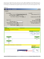
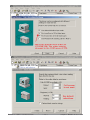
Configuring the PM for Modbus TCP Communications
Prior to establishing communications on the network a valid IP address must be established. There are
two ways in which an IP address can be established: Dynamic Host Configuration Protocol (DHCP, where
a DHCP server on the network provides an IP address); or a fixed IP address (manually entered). The PM
controller's default is set to DHCP. If the PM is brought up on the Ethernet network and there is no DHCP
server present the PM will assume address 169.254.1.1 as the factory default fixed IP address. To change the
fixed IP address or the IP selection method (DHCP or fixed) follow the steps below:
1. Push and hold the up and down arrow keys on the front panel for six seconds to go the the Setup Menu.
2. Push the up or down arrow key until [`CoM] (Communications Menu) appears in upper display and
[`SEt] in the lower display.
3. Push the green Advance Key ‰ to enter the Communications Menu [`CoM].
4. Push up arrow key to go to the Communications 2 Submenu. The upper display shows [```2], and the
lower display shows [`CoM].
5. Push the Advance Key ‰ until the upper display shows [dhCP] and lower display shows [iP;M]. Use the
up and or down arrow keys to change the addressing method.
6. If [F;Add] is selected above push the Advance Key ‰ and then the up arrow to change the first of four
parts of the IP address. Each part represents a byte which makes up the 32-bit IP address. Follow the
same steps to change each of the other three bytes to complete the IP address.
Note: Excessive writes to the PM may cause premature EEPROM failure. For more detail see the section entitled "Saving
Settings to Nonvolatile Memory".
Watlow EZ-ZONE™ Communications
•
15
•
Chapter 2 Mobbus RTU & TCP
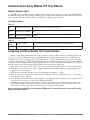
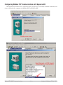
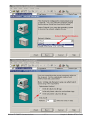
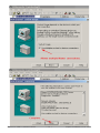
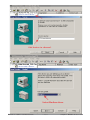
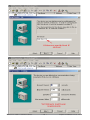
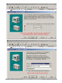
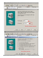
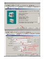
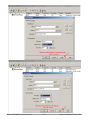
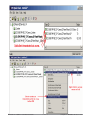
Configuring Modbus TCP Communications with KepserverEX
The following screenshots show a sequential step-by-step process to sucessfully establish communications
from the PM controller equipped with Modbus TCP and KepserverEX.
Watlow EZ-ZONE™ Communications
•
16
•
Chapter 2 Mobbus RTU & TCP
Watlow EZ-ZONE™ Communications
•
17
•
Chapter 2 Mobbus RTU & TCP
Watlow EZ-ZONE™ Communications
•
18
•
Chapter 2 Mobbus RTU & TCP
Watlow EZ-ZONE™ Communications
•
19
•
Chapter 2 Mobbus RTU & TCP
Watlow EZ-ZONE™ Communications
•
20
•
Chapter 2 Mobbus RTU & TCP
Watlow EZ-ZONE™ Communications
•
21
•
Chapter 2 Mobbus RTU & TCP
Watlow EZ-ZONE™ Communications
•
22
•
Chapter 2 Mobbus RTU & TCP
Watlow EZ-ZONE™ Communications
•
23
•
Chapter 2 Mobbus RTU & TCP
Watlow EZ-ZONE™ Communications
•
24
•
Chapter 2 Mobbus RTU & TCP
Watlow EZ-ZONE™ Communications
•
25
•
Chapter 2 Mobbus RTU & TCP
Watlow EZ-ZONE™ Communications
•
26
•
Chapter 2 Mobbus RTU & TCP
Watlow EZ-ZONE™ Communications
•
27
•
Chapter 2 Mobbus RTU & TCP
Watlow EZ-ZONE™ Communications
•
28
•
Chapter 2 Mobbus RTU & TCP
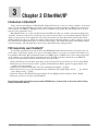
3
Chapter 3 EtherNet/IP
Introduction to EtherNet/IP
Today, with the introduction of EtherNet/IP (Industrial Protocol), a user can collect, configure, and control
using one protocol. EtherNet/IP is a network communication standard capable of handling large amounts of
data at speeds of 10 Mbps or 100 Mbps, and at up to 1,500 bytes per packet. The specification uses an open
protocol at the application layer.
EtherNet/IP makes use of the standard off-the-shelf Ethernet chip sets and the currently installed physical media (hardware connections) and incorporates what is known today as the Common Industrial Protocol
(CIP); an open protocol at the application layer fully managed by the Open DeviceNet Vendors Association
(ODVA, http://www.odva.org). CIP is the critical component providing the ability to collect, configure, and control utilizing both implicit messaging (real-time I/O messaging), and explicit messaging (information/configuration messaging), with full support for peer-to-peer and multi-master configurations.
PM Connectivity over EtherNet/IP
To establish communications with the PLC the EZ-ZONE™ PM controller must be connected to the network, where it will either assume or be given an IP address. There are two ways in which an IP address can
be established: Dynamic Host Configuration Protocol (DHCP, where a DHCP server on the network provides
an IP address); or a fixed IP address (manually entered). The PM controller's default is set to DHCP. To
change the IP addressing method to fixed IP follow the steps below:
1. Push and hold the up and down arrow keys on the front panel for six seconds to go the the Setup Menu.
2. Push the up or down arrow key until [`CoM] (Communications Menu) appears in upper display and
[`SEt] in the lower display.
3. Push the green Advance Key ‰ to enter the Communications Menu [`CoM].
4. Push up arrow key to go to the Communications 2 Submenu. The upper display shows [```2], and the
lower display shows [`CoM].
5. Push the Advance Key ‰ until the upper display shows [dhCP] and lower display shows [iP;M].
6. Push the up arrow to change to Fixed Address
Note: Excessive writes to the PM may cause premature EEPROM failure. For more detail see the section entitled "Saving
Settings to Nonvolatile Memory".
Watlow EZ-ZONE™ Communications
•
29
•
Chapter 3 Et herNet/IP
EtherNet/IP Indicator Lights
The PM has four indicator lights on the top of the controller, all of which are used with EtherNet/IP. The
characteristics of the Module Status and Network Status LED’s are defined by Open DeviceNet Vendors Association (ODVA), while the Active and Link indicator lights are defined in the Ethernet specification.
Module Status Indicator
Table 3.1
Indicator State
Summary
Requirement
Steady Off
No power
If no power is supplied to the device, the module status indicator
shall be steady off.
Steady Green
Device
operational
If the device is operating correctly, the module status indicator
shall be steady green.
Flashing Green
Standby
If the device has not been configured, the module status indicator
shall be flashing green.
Flashing Red
Minor fault
If the device has detected a recoverable minor fault, the module
status indicator shall be flashing red.
NOTE: An incorrect or inconsistent configuration would be considered a minor fault.
Steady Red
Major fault
If the device has detected a non-recoverable major fault, the module status indicator shall be steady red.
Flashing Green /
Red
Self-test
While the device is performing its power up testing, the module
status indicator shall be flashing green / red.
Network Status Indicator
Table 3.2
Steady Off
Not powered,
no IP address
If the device does not have an IP address (or is powered off), the
network status indicator shall be steady off.
Flashing Green
No connections
If the device has no established connections, but has obtained an
IP address, the network status indicator shall be flashing green.
Steady Green
Connected
If the device has at least one established connection (even to the
Message Router), the network status indicator shall be steady
green.
Flashing Red
Connection
timeout
If one or more of the connections in which this device is the target
has timed out, the network status indicator shall be flashing red.
This shall be left only if all timed out connections are reestablished or if the device is reset.
Steady Red
Duplicate IP
If the device has detected that its IP address is already in use,
the network status indicator shall be steady red.
Flashing Green /Red
Self-test
While the device is performing its power up testing, the network
status indicator shall be flashing green / red.
Link Status Indicator
Table 3.3
Steady Off
Not powered,
unknown link speed
If the device cannot determine link speed or power is off,
the network status indicator shall be steady off.
Red
Link speed = 10 Mbit
If the device is communicating at 10 Mbit, the link LED
will be red..
Green
Link speed = 100 Mbit
If the device is communicating at 100 Mbit, the link LED
will be green.
Activity Status Indicator
Table 3.4
Flashing Green
Detects activity
If the MAC detects activity, the LED will be flashing green.
Red
Link speed = 10Mbit
If the MAC detects a collision, the LED will be red.
Watlow EZ-ZONE™ Communications
•
30
•
Chapter 3 EtherNet/IP
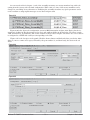
I/O Configuration using an Allen-Bradley Logix Family Processor
The setup steps may vary depending on the controller. The specific control used in the examples is a CompactLogix 1769-L32E. Follow the steps below to add and configure the PM as a generic Ethernet module.
1. In the I/O configuration, right click on the Ethernet Port, (in this case: 1769-L32E Ethernet Port LocalENB) and add a new module.
Figure 3.0
2. Select “Generic Ethernet Module” and click OK.
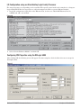
Configuring PM Properties using the RSLogix 5000
After clicking OK, the following screen will appear. You must complete all the fields in this screen except the
description field.
Figure 3.1
Watlow EZ-ZONE™ Communications
•
31
•
Chapter 3 Et herNet/IP
Name
This field, will automatically be used as the controller
name and will be used in the program when referencing PM inputs or outputs.
Description
No entry required.
Comm Format
As can be seen in the PM I/O assemblies below, the PM
data formats depend on the tag name being written to
or read from.
As can be seen in the chart below, the data types
used by the PM vary. Although multiple “Comm Formats” can be configured, for ease in configuration and
programming it is suggested that it be configured as
INT. Configuration examples will follow.
IP Address
Enter here, the DHCP or fixed IP address previously
acquired.
Assembly Instance
Input, PM to CompactLogix
This field identifies the Target to Originator (T Æ O)
input assembly 0x65 (101 decimal).
Output, CompactLogix to PM
This field identifies Originator to Target (O Æ T) output assembly 0x64 (100 decimal).
Configuration
The PM does not use the configuration instance 0x80
(128 decimal), however it still needs to be entered here.
Assembly Size
The assembly size is dependent upon the “Comm Format.”
T ÆO INT: 42 or DINT: 21
O Æ T INT: 40 or DINT: 20
The size for the configuration instance, although not
used, will always be set to 0.
Watlow EZ-ZONE™ Communications
•
32
•
Chapter 3 EtherNet/IP
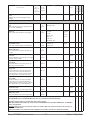
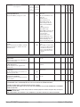
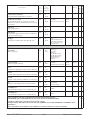
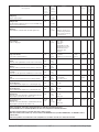
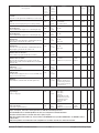
Table 3.5
Supported Attribute Data Types
CIP
PM
Access
Size (Bytes)
USINT
UByte
RW
1
SINT
Byte
RW
1
UINT
UWord
RW
2
INT
Word
RW
2
UDINT
ULong
RW
4
DINT
Long
RW
4
REAL
Float
RW
4
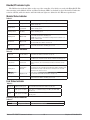
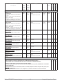
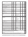
Target to Originator (T to O) - Default Assembly
Table 3.6
Attribute Name
EIP Class
ID
EIP Instance
ID
EIP Attribute
ID
Data
Type
Analog Input 1 Process Value
104
1
1
REAL
Analog Input 1 Eror Status
104
1
2
DINT
REAL
Analog Input 2 Process Value
104
2
1
Analog Input 2 Error Status
104
2
2
DINT
Alarm 1 State
109
1
9
DINT
Alarm 2 State
109
2
9
DINT
Alarm 3 State
109
3
9
DINT
Alarm 4 State
109
4
9
DINT
Digital Input 5 Status
110
1
5
DINT
Digital Input 6 Status
110
2
5
DINT
Control Mode Active
151
1
2
DINT
Heat Power
151
1
13
REAL
Cool Power
151
1
14
REAL
Limit State
112
1
6
DINT
Profile Start
122
1
1
DINT
Profile Action Request
122
1
11
DINT
Active File
122
1
3
DINT
Active Step
122
1
4
DINT
Active Set Point
122
1
5
REAL
Step Time Remaining
122
1
9
REAL
In using the input assembly define the following sizes based on the configured “Comm Format” in
RSLogix5000.
DINT: 21
INT: 42
Watlow EZ-ZONE™ Communications
•
33
•
Chapter 3 Et herNet/IP
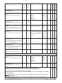
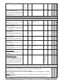
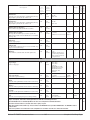
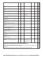
Originator to Target (O to T) - Default Assembly
Table 3.7
Attribute Name
EIP Class ID
EIP Instance
ID
EIP Attribute
ID
Data Type
Loop Control Mode
151
1
1
DINT
Closed Loop Set Point
107
1
1
REAL
Open Loop Set Point
107
1
2
REAL
Alarm 1 High Set Point
109
1
1
REAL
Alarm 1 Low Set Point
109
1
2
REAL
Alarm 2 High Set Point
109
2
1
REAL
Alarm 2 Low Set Point
109
2
2
REAL
Alarm 3 High Set Point
109
3
1
REAL
Alarm 3 Low Set Point
109
3
2
REAL
Alarm 4 High Set Point
109
4
1
REAL
Alarm 4 Low Set Point
109
4
2
REAL
Profile Action Request
122
1
11
DINT
Profile Start
122
1
1
DINT
Heat Proportional Band
151
1
6
REAL
Cool Proportional Band
151
1
7
REAL
Time Integral
151
1
8
REAL
Time Derivative
151
1
9
REAL
Heat Hysteresis
151
1
11
REAL
Cool Hysteresis
151
1
12
REAL
Deadband
151
1
10
REAL
In using the output assembly define the following sizes based on the configured “Comm Format” in
RSLogix5000.
DINT: 20
INT: 40
Note: Excessive writes to the PM may cause premature EEPROM failure. If using the O to T assembly it is recommended that EEPROM writes be disabled (factory default). For more detail see the section entitled "Saving Settings to Nonvolatile Memory".
Watlow EZ-ZONE™ Communications
•
34
•
Chapter 3 EtherNet/IP
Communications between ControlLogix &
the EZ-ZONE™ PM
Configuring the PM enables both real-time I/O
connections (implicit messaging) and non-time critical
(explicit messaging) communications. Information will
be transferred between the control and the PM using
either implicit and or explicit connections. All implicit
messages are sent and received cyclically at the rate
of the Requested Packet Interval (RPI), where explicit
messages are typically initiated via a message instruction in the control program. It is recommended that
the RPI be set above 100ms. Generally, explicit messages are used as a tool for configuration. For example,
to change the default T-to-O or O-to-T assembly structure in the PM from the factory defaults as defined
above, the user would use an explicit message instruction.
Ladder Logic Examples
First, let’s take a look at the “Comm Format”
briefly discussed earlier with a recommendation to
configure it as INT. In this section we will see why.
One of the advantages of using the Logix family
of controls is that users can define their own data
types. Creating two unique, user-defined data types
(T to O and O to T) makes programming the PLC to
communicate with the Watlow PM controller very
easy. The name given for these data types is up to
the user. In this example, the user-defined data
types and styles were created to match the default
PM O-to-T and T-to-O assemblies.
Notice in Figure 3.4 (PM T to O) that the first
location is identified as "Device Status." This does
not represent one of the 20 members, and it is required. Currently, if bit 16 is set to 1, as shown in
figure 3.2 below (PM to PLC), it indicates valid
communications between the Ethernet card and the
PM. If set to 0, communications have failed.
In the ladder logic examples that follow, please
note how the PM and its associated tags were configured.
Figure 3.2
Figure 3.3 & 3.4
Now, to use the new data types defined above. Two controller tags where created (see figure 3.5 & 3.6) and
when prompted for the data type, the user-defined data types defined above were selected.
Watlow EZ-ZONE™ Communications
•
35
•
Chapter 3 Et herNet/IP
Figure 3.5 & 3.6
You can now use simple logic to create instructions
to move implicitly the default assembly structures to
and from the PM. Recall that the name given to the
I/O module is also used as the I/O tags. Note in the
first copy instruction (input from PM to PLC) that the
name given to the module appears as the source (Watlow_PM). Likewise, in the second copy instruction
(output from PLC to PM) the destination tag reflects
the module name. The two copy instructions below
represent all that’s needed to send and receive data
from the PM. The copy instructions will copy source
tags to destination tags byte for byte, so no further
data conversion is needed.
Figure 3.7
Ladder Logic Example
In the likely event that the user wants to change the default assembly structures, this can be done using
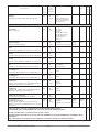
an explicit message. First, it is necessary to define the assembly setup. Note in Tables 3.8 and 3.9 that both
assemblies (O to T and T to O) are accessed via class 119, where the instance identifies input and output with
the attribute identifying the member within the instance.
Watlow EZ-ZONE™ Communications
•
36
•
Chapter 3 EtherNet/IP
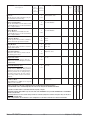
Originator to Target (PLC to PM)
Table 3.8
CIP
Class
ID
EIP
Instance
ID
EIP
Attribute
ID
OtoT Assembly Setup Instance 1
119
1
1
SINT
OtoT Assembly Setup Instance 2
119
1
2
SINT
OtoT Assembly Setup Instance 3
119
1
3
SINT
OtoT Assembly Setup Instance 4
119
1
4
SINT
OtoT Assembly Setup Instance 5
119
1
5
SINT
OtoT Assembly Setup Instance 6
119
1
6
SINT
OtoT Assembly Setup Instance 7
119
1
7
SINT
OtoT Assembly Setup Instance 8
119
1
8
SINT
OtoT Assembly Setup Instance 9
119
1
9
SINT
OtoT Assembly Setup Instance 10
119
1
10
SINT
OtoT Assembly Setup Instance 11
119
1
11
SINT
OtoT Assembly Setup Instance 12
119
1
12
SINT
OtoT Assembly Setup Instance 13
119
1
13
SINT
OtoT Assembly Setup Instance 14
119
1
14
SINT
OtoT Assembly Setup Instance 15
119
1
15
SINT
OtoT Assembly Setup Instance 16
119
1
16
SINT
OtoT Assembly Setup Instance 17
119
1
17
SINT
OtoT Assembly Setup Instance 18
119
1
18
SINT
OtoT Assembly Setup Instance 19
119
1
19
SINT
OtoT Assembly Setup Instance 20
119
1
20
SINT
CIP
Class
ID
EIP
Instance
ID
EIP
Attribute
ID
Data
Type
TtoO Assembly Setup Instance 1
119
2
1
SINT
TtoO Assembly Setup Instance 2
119
2
2
SINT
TtoO Assembly Setup Instance 3
119
2
3
SINT
TtoO Assembly Setup Instance 4
119
2
4
SINT
TtoO Assembly Setup Instance 5
119
2
5
SINT
TtoO Assembly Setup Instance 6
119
2
6
SINT
TtoO Assembly Setup Instance 7
119
2
7
SINT
TtoO Assembly Setup Instance 8
119
2
8
SINT
TtoO Assembly Setup Instance 9
119
2
9
SINT
TtoO Assembly Setup Instance 10
119
2
10
SINT
TtoO Assembly Setup Instance 11
119
2
11
SINT
TtoO Assembly Setup Instance 12
119
2
12
SINT
TtoO Assembly Setup Instance 13
119
2
13
SINT
TtoO Assembly Setup Instance 14
119
2
14
SINT
TtoO Assembly Setup Instance 15
119
2
15
SINT
TtoO Assembly Setup Instance 16
119
2
16
SINT
TtoO Assembly Setup Instance 17
119
2
17
SINT
TtoO Assembly Setup Instance 18
119
2
18
SINT
TtoO Assembly Setup Instance19
119
2
19
SINT
TtoO Assembly Setup Instance 20
119
2
20
SINT
Attribute Name
DataType
Structure of 8-bit Data Type:
{0xCC, 0xII, 0xAA}
Target to Originator (PM to PLC)
Table 3.9
Attribute Name
Watlow EZ-ZONE™ Communications
•
37
•
Structure of 8-bit Data Type:
{0xCC, 0xII, 0xAA}
Chapter 3 Et herNet/IP
For example, the screen captures below explain and illustrate how to change a given member for both the
O-to-T and T-to-O assemblies. To change other members within either instance, simply change the instance (1
or 2) and attribute value (1 to 20) in the MSG instruction. For a better understanding of what happens when
the instruction is enabled, take a closer look at the message instruction configuration and its associated tags.
Figure 3.8
In configuring the MSG instruction it is important to use hexidecimal entries for the class, instance and
attribute. In the example below (figure 3.9) the 16th location (attribute 10) of the T-to-O assembly structure
(instance 1) will be changed. Looking at figure 3.6 above you will see that the 16th member of the T-to-O assembly defaults to “Profile Action Request.” Once the configuration is complete, click on the communication
tab and define the path to the PM.
When the MSG instruction above is enabled this member will be overwritten, and the new attribute (state
of digital output 6) will be defined by the class, instance and attribute contained in the source element (see
figure 3.11 below).
Figure 3.9 & 3.10
Figure 3.11
Each member in both the O-to-T and T-to-O assemblies can be changed in this manner. Also, any valid class,
instance and attribute not found in the O-to-T and T-to-O assemblies can be read or written to explicitly using a rung of logic similar to the example in figure 3.3h
Watlow EZ-ZONE™ Communications
•
38
•
Chapter 3 EtherNet/IP
Saving Settings to Non-volatile Memory
When controller settings are entered from the controller front panel or a remote user interface (RUI)
changes are always saved to non-volatile memory (EEPROM). If the controller loses power or is switched off
its settings will be restored when power is reapplied.
The EEPROM will wear out after about 1,000,000 writes, which should not be a problem with changes
made from the panel or RUI. However if the controller is receiving instructions from a PLC or a computer
through a network connection, the EEPROM could, over time, wear out.
By default, settings made through the network are not saved to nonvolatile memory (59). However, every
time a setting is changed through the front panel or RUI, all of the controller settings are saved to EEPROM,
regardless of the setting of nonvolatile memory save. This parameter can only be changed via the network
protocol (i.e., Modbus RTU, Modbus TCP, or EtherNet/IP) and will always be saved to EEPROM.
Non-volatile Save
Modbus Addr: 2494
EtherNet/IP & DeviceNet
Class: 150
Instance: 1
Attribute: 8
Enumeration: yes = 106, no = 59
Note:
Disabling EEPROM writes is available with PM firmware revision 2 and above.
Watlow EZ-ZONE™ Communications
•
39
•
Chapter 3 Et herNet/IP
4
Chapter 4 DeviceNet
Introduction to DeviceNet
DeviceNet is a low-cost communication link that connects industrial devices over a common network
(such as: Watlow temperature controllers, limit switches, photoelectric sensors, proximity sensors, valve
manifolds, motor starters, process sensors, bar code readers, variable frequency drives, panel displays, and
operator interfaces) to higher-level devices such as programmable controllers and computers. DeviceNet, like
EtherNet/IP uses the proven Common Industrial Protocol (CIP) to provide the control, configuration, and
data collection capabilities for industrial devices. Being that this is an open protocol there are many independent vendors offering a wide array of devices to the end user. There are four components needed to read
and or write any parameters to the PM control:
1. Node address or MAC ID (0 - 63)
2. Class ID (1 to 255)
3. Instance ID (0 to 255)
4. Attribute ID (1 to 255)
Since both DeviceNet and EtherNet/IP use CIP you will find the class, instance, and attributes in the tables
that follow (Operations, Setup, Profile and Factory) are the same.
DeviceNet Communications
Although it is not an ODVA requirement for each node in a deviceNet network to have a Module Status
and a Network Status indicator the EZ-ZONE™ PM does. The meaning of each of these LEDs is defined in
table 1 and 2 below.
Table 1. Module Status (MOD) Indicator LED
Indicator LED
Description
Off
No power is applied to the device.
Flashing Green-Red
The device is performing a self-test.
Flashing Red
Major Recoverable Fault.
Red
Major Unrecoverable Fault.
Green
The device is operating normally.
Table 2. Network Status (NET) Indicator LED
Indicator LED
Description
Off
The device is not online. The device has not completed the duplicate MAC ID test yet. The device may
not be powered..
Green
The device is online and has connections in the established state. For a Group 2 Only device it means
that the device is allocated to a Master.
Red
Failed communication device. The device has detected an error that has rendered it incapable of
communicating on the network (duplicate MAC ID or
Bus-off).
Flashing Green
The device is online, but no connection has been allocated or an explicit connection has timed out.
Flashing Red
A poll connection has timed out.
Watlow EZ-ZONE™ Communications
•
40
•
Chapter 4 DeviceNet
Setting DeviceNet Communication Parameters from the Front Panel
Valid DeviceNet node addresses range from 0 - 63 and there are three available baud rates for the user
to choose from: 125Kb, 250Kb, or 500Kb. The EZ-ZONE™ PM factory defaults are listed below:
Node address = 63, Baud rate = 125Kb
If the node address needs to be changed go to the control "Setup Page" following the steps below:
1. Push and hold the up and down arrow keys on the front panel for six seconds to go the the Setup Menu.
2. Push the up or down arrow key until [`CoM] (Communications Menu) appears in upper display and
[`SEt] in the lower display.
3. Push the green Advance Key ‰ to enter the Communications Menu [`CoM].
4. Push up arrow key to go to the Communications 2 Submenu. The upper display shows [2], and the lower
display shows [`CoM].
5. Push the Advance Key ‰ where the upper display will show 63 (default node address) and lower display
shows [Ad;d].
6. Push the down arrow to change the DeviceNet node address.
If the baud rate needs to be changed go to the control "Setup Page" following the steps below:
1. Push and hold the up and down arrow keys on the front panel for six seconds to go the the Setup Menu.
2. Push the up or down arrow key until [`CoM] (Communications Menu) appears in upper display and
[`SEt] in the lower display.
3. Push the green Advance Key ‰ to enter the Communications Menu [`CoM].
4. Push up arrow key to go to the Communications 2 Submenu. The upper display shows [2], and the lower
display shows [`CoM].
5. Push the Advance Key ‰ twice where the upper display will show 125 (default baud rate) and lower display shows [bAud].
6. Push the up or down arrow to change to the desired baud rate (125Kb, 250Kb, or 500Kb)
Once the above parameters have been changed cycle power on the DeviceNet network for the new parameters to take affect.
There are three prompts delivered to the user from the front panel of the PM that are related to DeviceNet. Two of which are defined above, [bAud] (network baud rate or speed) and [Ad;d] (network node address). There is one other which is identified and explained below:
[FC;E] (Quick Connect)
Quick Connect
The Quick Connect feature is an option enabled on a node-by-node basis. When enabled, a
device transitions to the OnLine state concurrently with sending the first Duplicate MACID
Request message. The device is still required to execute the network State Tranisition Diagram (STD)
(Used to describe object behavior), including going offline anytime a Duplicate MACID response message
is received.
Note:
Although this feature allows a device to begin participating in network activity faster, it is at the expense
of a delay in the duplicate node detection algorithm. It is left up to the user to guarantee that no nodes
exist with the same MAC ID and that no more than one Client device is configured to access the same
device using the Predefined Master/Slave Connection Set. Bus errors may occur if either of these conditions exists. This feature is enabled within a device through a non-volatile attribute in the DeviceNet
object. A device shall have this feature disabled (attribute set to ‘0’) as the factory default If it is desired
to change this parameter from its default state of no to yes, go to the control "Setup Page" following the
steps below:
Watlow EZ-ZONE™ Communications
•
41
•
Chapter 4 DeviceNet
1. Push and hold the up and down arrow keys on the front panel for six seconds to go the the Setup Menu.
2. Push the up or down arrow key until [`CoM] (Communications Menu) appears in upper display and
[`SEt] in the lower display.
3. Push the green Advance Key ‰ to enter the Communications Menu [`CoM].
4. Push up arrow key to go to the Communications 2 Submenu. The upper display shows [```2], and the
lower display shows [`CoM].
5. Push the Advance Key ‰ three times where the upper display will show [no] (default) and lower display
shows [FC;E].
6. Push the up or down arrow to change from no to yes.
DeviceNet Connector
As can be seen in graphics below there is just one connector that is used to connect your PM control to
the DeviceNet network. Figure 4.0 shows the back side the PM control where the connector on the far left is
identified as slot A, the middle slotB, and the far right as slot C. The DeviceNet card will always reside in the
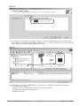
middle slot or slot B and will be connected into the network accordingly. Figure 4.1 shows the Watlow supplied DeviceNet connector along with signal orientation.
Figure 4.0
V+
CAN_H
Shield
CAN_L
V-
Figure 4.1
Signal
Function
V+
DeviceNet power
CAN_H
Positive side of the DeviceNet bus
Shield
Shield interconnect
CAN_L
Negative side of the DeviceNet bus
V-
DeviceNet power return
Commissioning the PM Using RSNetWorx for DeviceNet
The first step in getting your PM control up and running is to commission it over DeviceNet. The commissioning process involves identifying and selecting the appropriate communication parameters, node address,
and lastly, memory mapping so as to enable passing data to and from specific addresses in the Device-Net
scanner and the PLC. Set the baud rate and node address (as was described above) prior to connecting it on
the network to avoid conflicts with baud rate or other devices on the network.
After the PM is physically connected in the network you should notice that the "Module" LED (MS, as
identified on the PM) should be solid green where the "Network" LED (NS, as identified on the PM) should be
blinking green (see definition above). Follow the steps below to establish connectivity over the network:
1. Open up RSLinx and configure the appropriate driver for the DeviceNet hardware you have on-hand.
Note: Keep in mind that there is a lot of available hardware to choose from. In the example below the hardware chosen is the Allen-Bradley 1770-KFD. You must first identify the hardware you are using.
2. Verify that you have communications using the configured driver & hardware by clicking on RSWho.
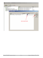
- Notice in figure 4.2 that three devices appear on the network where one device has a question mark. The
question mark does not indicate a problem but does indicate that the EDS file associated with this device
is not yet registered.
Watlow EZ-ZONE™ Communications
•
42
•
Chapter 4 DeviceNet
Figure 4.2
3. The next step in the process of commissioning the network is to open up RSNetWorx for DeviceNet. Once
opened up go online selecting the hardware you previously configured in RSLinx. In figure 4.3 we again
see that node 7 has a question mark but now within RSNetWorx we can also see that this device and its
associated EDS file is not registered.
Figure 4.3
4. There are two ways to register the Watlow EZ-ZONE™ control on the network:
1. Click on "Tools" and then "EDS Wizard" and point the software to the location of the Watlow provided
electronic data sheet (EDS) and "Register an EDS File".
2. Click on "Tools" and then "EDS Wizard" and then "Create a EDS file".
It is slightly easier to register the Watlow control if you have on-hand the Watlow provided EDS file. If
you do not have the EDS file and do not want to wait to acquire it then option two above is the way to
go. Next, we will now take a closer look at the steps involved for both options defined above.
Watlow EZ-ZONE™ Communications
•
43
•
Chapter 4 DeviceNet
Registering an EZ-ZONE™ PM Using Watlow Provided EDS File
1. With RSNetWorx open and running as shown in figure 4.3 click on "Tools", then "EDS Wizard", then
"Register an EDS File".
2. Click the browse button in figure 4.4 to point the software to the Watlow provided EDS file then click
the next button.
Figure 4.4
3. The graphic below (figure 4.5) shows that the file found passes the evaluation executed through RS
NetWorx. Click the next button to proceed.
Figure 4.5
As can be seen at the bottom of figure 4.4 if there is an icon file with the same name as the EDS file
there will be an automatic association of the icon with this device. We see in figure 4.6 that this association
did indeed occur. If the icon didn't exist than RSNetWorx will use a default icon to graphically display the device when browsing the network.
Watlow EZ-ZONE™ Communications
•
44
•
Chapter 4 DeviceNet
Figure 4.6
4. At this point the registration is complete. Click next until the finish button appears and then click
finish. Figure 4.7 below now shows Watlow Electric Inc. as a vendor and we can also see the graphical
representation of the EZ-ZONE™ PM on the network.
Figure 4.7
Double clicking on the Watlow EZ-ZONE™ icon will open up a window that will contain four tabs.
- General (Device Identity)
- Parameters (Device Identity, Device Name, Load factory defaults)
- I/O Data Size (Input bytes, Output bytes)
- EDS File (View file)
Watlow EZ-ZONE™ Communications
•
45
•
Chapter 4 DeviceNet
Registering an EZ-ZONETM PM Without a Watlow EDS File
1. With RSNetWorx open and running as shown in figure 4.3 click on "Tools", then "EDS Wizard", then
"Create an EDS File".
2. Click the next button
Figure 4.8
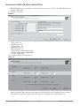
3. Figure 4.8 shows the next screen that appears. Enter the information for each field as shown below:
- Vendor ID = 153
- Product Type = 12
- Product Code = 301
- Major Revision = 1
- Minor Revision = 1
- Vendor Name = Watlow Electric Inc.
- Product Name = Watlow EZ-ZONE™
- Catalog = A007-2841
Once complete click on the next button.
Figure 4.9
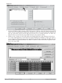
4. As shown above click on the Polled check box and 84 input bytes and 80 output bytes. Click the next
button when done. The next screen that appears will identify the device graphically with a default
icon. Click the next button and then the finish button to complete the registration process.
Watlow EZ-ZONE™ Communications
•
46
•
Chapter 4 DeviceNet
Mapping the EZ-ZONE™ PM Into PLC Memory
1. Double click on your DeviceNet scanner and once open (figure 4.10) click on the "Module" tab.
2. Click the "Upload" button
Figure 4.10
3. Once the upload is complete click on the "Platform" drop down box and select the appropriate control.
In this case, the PM is connected to a CompactLogix. This selection will have an impact on the addres
ing for the MicroLogix is a 16-bit machine where the CompactLogix is 32-bits.
Figure 4.11
4. After selecting the CompactLogix as the platform click on the "Scanlist" tab. As figure 4.12 shows, the
scanner will display all available devices on the network and all of those currently in the scanlist. In
this case there is only one device on the network.
5. Click on the Watlow EZ-ZONE™ control and then click on the right arrow button located in the mid
dle of the screen. Since the "Automap on Add" check box is checked when the right arrow button is
pushed the PM control will be automatically mapped into specific addresses for both the input and the
output.
Watlow EZ-ZONE™ Communications
•
47
•
Chapter 4 DeviceNet
Figure 4.12
4. As was stated previously, because the PLC platform chosen utilizes a 32-bit word we can see in figure
4.13 that the PM assembly structure will be mapped into 1:I.Data[0 - 20] in the PLC. Recall from our
earlier exercise of registering the PM on the network that there are 84 total input bytes divided by 4
bytes per word which equals 21 words. This represents the T to O assembly structure (see Table 3.6)
where the data is sourced at the target (PM) and sent to the originator (PLC).
5. Clicking on the "Output" tab will yield similar but slightly different results. Different in that there
are a total of 80 output bytes versus 84 for the inputs. Dividing that number by 4 bytes per word we
can see that there will be 20 output words consumed by this module: 1:O.Data[0 - 19]. This will repre
sent the PM O to T assembly structure (see Table 3.7) which is sourced in the PLC (originator) and
sent to the target (PM).
Figure 4.13
Watlow EZ-ZONE™ Communications
•
48
•
Chapter 4 DeviceNet
Configure and Program an Allen-Bradley CompactLogix L32E
Now that the DeviceNet scanner module has been configured lets take a closer look at the configuration
in the PLC. After adding the DeviceNet scanner module to the PLC I/O structure notice the input and output
size required to read and write to the the PM default assembly structure. If you do not have a need to work
with the entire assembly structure than the I/O sizes can be decreased accordingly.
Figure 4.14
Because the Logix family of controls allows the user to create user defined data types it is suggested that
you do so for ease of programming. An example of two user defined data types were created to represent the
default O to T and T to O assembly structures. Notice that a couple of members identified in the T to O structure are identified as "Not Used". They are identified as such for two reasons:
1. When the PM PID control is equipped with the DeviceNet card analog input 2 is not an available option.
2. When the PM PID control is equipped with the DeviceNet card the integrated limit is not an available op
tion.
Keep in mind that these particular members (and all members for that matter) can be modified according
to your liking following the step-by-step procedure beginning under the section entitled "Ladder Logic Example"..
Figure 4.15
Watlow EZ-ZONE™ Communications
•
49
•
Chapter 4 DeviceNet
Figure 4.16
Again note that both of the above screen shots represent the factory defaults and that each member can
be changed. Now create two controller tags that will use the data types just created in figure 4.15 and 4.16.
As can be seen below the tag name is identified as PMDnet_T_to_O. Notice the data type selected (arrow, figure 4.17). Notice too, that the first member is identified as "Module Status"; bit 12 and bit 16 represent good
communications between the DeviceNet card and the PM.
Figure 4.17
Figure 4.18
Watlow EZ-ZONE™ Communications
•
50
•
Chapter 4 DeviceNet
A user may want to monitor the status of these bits in the PLC program. If either of these bits goes to "0",
communications have failed between the DeviceNet card and the PM
Taking a closer look at previous work, specifically, where the PM was mapped into PLC memory via the
scanners scanlist (RSNetWorx) we can see below in figure 4.19 and 4.20 a direct correlation between the PLCs
controller tags (screen shot below) and figure 4.13. In the addresses circled below in figure 4.19 notice that
from the PLCs perspective that the scanner is identified as sitting in slot 1 and the "I" indicates inputs which
represents, in this case, the default T to O assembly from the PM. In figure 4.20 we see the same relationship
for the O to T assembly which represents data sent from the PLC to the PM..
Figure 4.19
Figure 4.20
Notice that in figure 4.19 above that there is data coming in to the PLC delivered by the PM, this is without any programming! In figure 4.20 we can also see that since there is no program in the PLC that there is
no data being sent to the PM. Lets take a closer look at some simple programming so that we can send data
from the PLC to te PM.
Watlow EZ-ZONE™ Communications
•
51
•
Chapter 4 DeviceNet
Sending Data From PLC to PM via Ladder Logic
In figure 4.21 two copy instructions are used to move the data to and from the PM via the PLC logic.
Figure 4.21
Changing the Default Assembly Structure in the PM
In figure 4.17 there were three members of the T to O assembly identified as not used due to the PM
model used. As an example, lets change the default assembly of the fourth member (currently identified as
"PMDnet_T_to_O.AIN_2_PV"), to "Autotune Set Point". Step-by-step, we will now look at what is required to
change the default assembly for the third member with the status word being member 0. This same logic with
some minor modifications can be used to modify any member of either assembly, input or output.
1. In figure 3.3g find the class, instance, and attribute that needs to be changed. In this case, because the sta
tus word is not shown (member 0) we will need to redefine Class 119, Instance 2, and Attribute 3.
2. Find the parameter "Autotune Set Point" in the Operations Page of this manual to acquire the class, in
stance, and attribute (CIA) information. In this case, the CIA is 151, 1, and 20 respectively. Figure 4.23
shows the hexadecimal equivalent of 97, 1, and 14.
Keep in mind that in the example below that it is the T to O assembly that will be modified. The user will
be able to see what the current Autotune Set Point is as it is currently in the PM. If it is desired to be able to
change the Autotune Set Point via the PLC then similar logic would need to be created to modify the O to T
assembly as well. In fact, all that is really needed is that the instance identified in the MSG instruction below
be changed to one instead of two and then modify the attribute desired. As can be seen in figure 3.3f instance
one of class 119 represents the O to T assembly where instance two represents the T to O (figure 3.3g).
Figure 4.22
Watlow EZ-ZONE™ Communications
•
52
•
Chapter 4 DeviceNet
As was stated earlier in chapter 3 each of the assembly structures are twenty members long with each
coming from the factory with a default configuration (Table 3.6 & 3.7). Any of the twenty members can be
changed to your liking. As an alternative to modifying the assembly structures any given parameter can be
read or written to using explicit messages as was done in figure 4.22.
Figure 4.23
Figure 4.24 below shows the configuration screen for MSG instruction in figure 4.22. Notice that the instruction is looking for Hex characters for the class, and attribute fields. As shown below, 77h (Class) equals
119d, 2d (Instance), 3h (Attribute). The source element is shown above in figure 4.23 where one can see that it
is configured as a SINT with each byte corresponding to the CIA.
Figure 4.25 is the last piece of the puzzle. Click the browse button and find and select your device. After
doing so, enter a comma and a space, followed by the port number (2), and then lastly, the device node address.
Figure 4.24
Figure 4.25
Watlow EZ-ZONE™ Communications
•
53
•
Chapter 4 DeviceNet
5
Chapter 5: Flashing Firmware
Flashing EZ-ZONE™ PM Firmware
There are occasions when Watlow may make modifications to the control firmware. If you are trying to
determine if you have the latest firmware in your control call (507-494-5656) or e-mail (wintechsupport@
watlow.com) Watlow technical support. In the event that Watlow technical support suggests that the control
firmware be upgraded there is utility software that will be provided along with the executable to flash the
control. The screen shots below illustrate a step-by-step approach to flashing your control.
1. Connect USB to EIA-485 converter to PC
2. Install USB driver from CD if prompted
3. Connect converter to EZ-ZONETM PM
4. Unzip files to directory
5. Execute PM Flash exe file
6. When a EZ-ZONE™ PM is located, the message below is displayed
Figure 5.1
7. Press 1 to select the controller at this address
Figure 5.2
8. Model number and firmware version in controller is displayed
9. Press ‘Y’ to start download - upgrade
Figure 5.3
10. PM switches to flash mode
11. PM LED display blanks then flashes one segment
Watlow EZ-ZONE™ Communications
•
54
•
Chapter 5 Flashing Firmware
Figure 5.4
12. Then memory is erased
Figure 5.5
13. Progress on programming is displayed.
14. Block count increments during programming
15. Program closes when complete
Watlow EZ-ZONE™ Communications
•
55
•
Chapter 5 Flashing Firmware
6
Chapter 6: Operations Page
Modbus
CIP
(less
class
40,001 instance
offset) attribute
read/
read/
write
write
Range
Default
Data
Type
EZ-ZONE™
PM Limt*
EZ-ZONE™
PM PID*
EZ-ZONE™
PM Int.*
Parameter name
Description
Analog Input Menu
Analog Input 1 Submenu
Analog Input 1
Process Value
View the process value.
360 r
104
1
1r
-1,999.000 to 9,999.000°F or
units
-1,128.000 to 5,537.000°C
Analog Input 1
Error Status
View the cause of the most recent error.
362 r
104
1
2r
None (61)
Open (65)
Shorted (127)
Measurement Error (140)
Bad Calibration Data (139)
Ambient Error (9)
RTD Lead Resistance Error
(141)
382 r/w
104
1
12 r/w
-1,999.000 to 9,999.000°F or
units
-1,110.555 to 5,555.000°C
Analog Input 2
Process Value
View the process value.
440 r
104
2
1r
-1,999.000 to 9,999.000°F or
units
-1,128.000 to 5,537.000°C
Analog Input 2
Error Status
View the cause of the most recent error.
442 r
104
2
2r
None (61)
Open (65)
Shorted (127)
Measurement Error (140)
Bad Calibration Data (139)
Ambient Error (9)
RTD Lead Resistance Error
(141)
462 r/w
104
2
12 r/w
-1,999.000 to 9,999.000°F or
units
-1,110.555 to 5,555.000°C
Analog Input 1
Calibration Offset
Offset the input reading to compensate for
lead wire resistance or other factors that
cause the input reading to vary from the actual process value.
floating
point
X
X
X
None
integer
X
X
X
0.0
floating
point
X
X
X
floating
point
X
None
integer
X
0.0
floating
point
X
Analog Input 2 Submenu
Analog Input 2
Calibration Offset
Offset the input reading to compensate for
lead wire resistance or other factors that
cause the input reading to vary from the actual process value.
Integers are unsigned, 16-bit values. Floating point values are IEEE 754 32-bit floating point values.
The default Modbus order is Low Word-High Word. The order can be changed in the Communications Menu.
PID
Int.
The default serial data format is: 9,600 baud; 8 data bits; no parity; 1 stop bit.
NOTE: Avoid continuous writes within loops. Excessive writes to the EEPROM will cause premature EEPROM failure. The EEPROM is
rated for 1,000,000 writes.
Underlined parameters are not accessable using a remote user's interface (RUI) or the controller's front panel. They can only be accessed using communications.
*Some of the parameters are not functional in some configurations of each model. Check the user's manual for information.
Watlow EZ-ZONE™ Communications
•
56
•
Chapter 6 Operations Page
Lmt.
Modbus
CIP
(less
class
40,001 instance
offset) attribute
read/
read/
write
write
Range
Default
Data
Type
EZ-ZONE™
PM Limt*
EZ-ZONE™
PM PID*
EZ-ZONE™
PM Int.*
Parameter name
Description
Digital Input/Output Menu
Digital Input or Output 5 Submenu
Digital Output 5
Output State
View the state of this output.
1012 r
106
5
7r
On (63)
Off (62)
integer
X
X
X
Digital Input 5
Event Status
View this event input state.
1328 r
110
1
5r
Inactive (41)
Active (5)
integer
X
X
X
Digital Output 6
Output State
View the state of this output.
1042 r
106
6
7r
On (63)
Off (62)
integer
X
X
X
Digital Input 6
Event Status
View this event input state.
1348 r
110
2
5r
Inactive (41)
Active (5)
integer
X
X
X
Limit
Low Set Point
Set the low process value that will trigger
the limit.
684 r/w
112
1
3 r/w
-1,999.000 to 9,999.000°F or
units
-1,128.000 to 5,537.000°C
0.0°F or
units
-18.0°C
floating
point
X
X
Limit
High Set Point
Set the high process value that will trigger
the limit.
686 r/w
112
1
4 r/w
-1,999.000 to 9,999.000°F or
units
-1,128.000 to 5,537.000°C
0.0°F or
units
-18.0°C
floating
point
X
X
Limit
Clear Request
Write to this register to clear a limit state.
680 w
112
1
1w
0
integer
X
X
Limit
State
View the limit state.
690 r
112
1
6r
Off (62)
None (61)
High (51)
Low (52)
Error (28)
integer
X
X
Monitor
Control Mode Active
View the current control mode.
1882 r
151
1
2r
Off (62)
Auto (10)
Manual (54)
integer
X
X
Monitor
Heat Power
View the current heat output level.
1904 r
151
1
13 r
0.0 to 100.0%
0.0
floating
point
X
X
Monitor
Cool Power
View the current cool output level.
1906 r
151
1
14 r
-100.0 to 0.0%
0.0
floating
point
X
X
Digital Input or Output 6 Submenu
Limit Menu
Monitor Menu
Integers are unsigned, 16-bit values. Floating point values are IEEE 754 32-bit floating point values.
The default Modbus order is Low Word-High Word. The order can be changed in the Communications Menu.
PID
Int.
Lmt.
The default serial data format is: 9,600 baud; 8 data bits; no parity; 1 stop bit.
NOTE: Avoid continuous writes within loops. Excessive writes to the EEPROM will cause premature EEPROM failure. The EEPROM is
rated for 1,000,000 writes.
Underlined parameters are not accessable using a remote user's interface (RUI) or the controller's front panel. They can only be accessed using communications.
*Some of the parameters are not functional in some configurations of each model. Check the user's manual for information.
Watlow EZ-ZONE™ Communications
•
57
•
Chapter 6 Operations Page
Modbus
CIP
(less
class
40,001 instance
offset) attribute
read/
read/
write
write
Range
Monitor
Closed Loop Active Set Point
View the closed loop set point currently in
effect.
2172 r
107
1
7r
-1,999.000 to 9,999.000°F or
units
-1,128.000 to 5,537.000°C
Monitor
Open Loop Active Set Point
View the open loop set point currently in
effect.
2174 r
107
1
8r
Monitor
Filtered Process Value Active, Input 1
View the current filtered process value using
this control input.
402 r
Monitor
Filtered Process Value Active, Input 2
View the current filtered process value using
this control input.
Default
75°F or
units
24°C
Data
Type
EZ-ZONE™
PM Limt*
EZ-ZONE™
PM PID*
EZ-ZONE™
PM Int.*
Parameter name
Description
floating
point
X
X
-100.0 to 100.0
floating
point
X
X
104
1
22 r
-1,999.000 to 9,999.000°F or
units
-1,128.000 to 5,537.000°C
floating
point
X
X
X
482 r
104
2
22 r
-1,999.000 to 9,999.000°F or
units
-1,128.000 to 5,537.000°C
floating
point
X
X
X
Monitor
Unfiltered Process Value Active, Input 1
View the current unfiltered process value using the control input.
360 r
104
1
1r
-1,999.000 to 9,999.000°F or
units
-1,128.000 to 5,537.000°C
floating
point
X
X
X
Monitor
Unfiltered Process Value Active, Input 2
View the current unfiltered process value using the control input.
440 r
104
2
1r
-1,999.000 to 9,999.000°F or
units
-1,128.000 to 5,537.000°C
floating
point
X
X
X
Monitor
Alarm 1 State
View the state of alarm 1.
1496 r
109
1
9r
Startup (88)
None (61)
Blocked (12)
Alarm Low (8)
Alarm High (7)
Error (28)
integer
X
X
X
Monitor
Alarm 2 State
View the state of alarm 2.
1546 r
109
2
9r
Startup (88)
None (61)
Blocked (12)
Alarm Low (8)
Alarm High (7)
Error (28)
integer
X
X
X
Monitor
Alarm 3 State
View the state of alarm 3
1596 r
109
3
9r
Startup (88)
None (61)
Blocked (12)
Alarm Low (8)
Alarm High (7)
Error (28)
integer
X
X
X
Monitor
Alarm 4 State
View the state of alarm 4
1646 r
109
4
9r
Startup (88)
None (61)
Blocked (12)
Alarm Low (8)
Alarm High (7)
Error (28)
integer
X
X
X
Monitor
Ambient Temperature, Input 1
View the ambient temperature.
366 r
104
1
4r
-1,999.000 to 9,999.000°F or
units
-1,128.000 to 5,537.000°C
floating
point
X
X
X
Integers are unsigned, 16-bit values. Floating point values are IEEE 754 32-bit floating point values.
The default Modbus order is Low Word-High Word. The order can be changed in the Communications Menu.
PID
Int.
Lmt.
The default serial data format is: 9,600 baud; 8 data bits; no parity; 1 stop bit.
NOTE: Avoid continuous writes within loops. Excessive writes to the EEPROM will cause premature EEPROM failure. The EEPROM is
rated for 1,000,000 writes.
Underlined parameters are not accessable using a remote user's interface (RUI) or the controller's front panel. They can only be accessed using communications.
*Some of the parameters are not functional in some configurations of each model. Check the user's manual for information.
Watlow EZ-ZONE™ Communications
•
58
•
Chapter 6 Operations Page
Modbus
CIP
(less
class
40,001 instance
offset) attribute
read/
read/
write
write
Range
Default
Data
Type
EZ-ZONE™
PM Limt*
EZ-ZONE™
PM PID*
EZ-ZONE™
PM Int.*
Parameter name
Description
Monitor
Ambient Temperature, Input 2
View the ambient temperature.
446 r
104
2
4r
-1,999.000 to 9,999.000°F or
units
-1,128.000 to 5,537.000°C
floating
point
X
X
X
Monitor
Bumpless Set Point
View the set point that will take effect if a
bumpless transfer occurs.
2178 r
107
1
10 r
-1,999.000 to 9,999.000°F or
units
-1,128.000 to 5,537.000°C
floating
point
X
X
Monitor
Control Loop Output Power
View the output power.
1908 r
151
1
15 r
-100.0 to 100.0
floating
point
X
X
Monitor
Event 1 Status
View the status of event 1.
1328 r
110
1
5r
Inactive (41)
Active (5)
integer
X
X
X
Monitor
Event 2 Status
View the status of event 2.
1348 r
110
2
5r
Inactive (41)
Active (5)
integer
X
X
X
Monitor
EZ Key Status
View the status of event 3.
1368 r
110
3
5r
Inactive (41)
Active (5)
integer
X
X
X
Monitor
Limit State
View the limit state.
690 r
112
1
6r
Off (62)
None (61)
Limit High (51)
Limit Low (52)
Error (28)
integer
X
Monitor
Ramp Active Set Point
View the current ramp set point.
2190 r
107
1
16 r
-1,999.000 to 9,999.000°F or
units
-1,128.000 to 5,537.000°C
floating
point
X
Monitor
Ramp Target Set Point
View the target ramp set point.
2198 r
107
1
20 r
-1,999.000 to 9,999.000°F or
units
-1,128.000 to 5,537.000°C
floating
point
Loop
Remote Enable
Switch control to the remote set point.
2200
r/w
107
1
21 r/w
No (59)
Yes (106)
No
integer
X
Loop
Remote Set Point Type
Select how the remote set point will be determined.
2202
r/w
107
1
22 r/w
Auto (closed loop) (10)
Manual (open loop) (54)
Auto
integer
X
Loop
Control Mode
Select the method that the controller will
use to control.
1880
r/w
151
1
1 r/w
Off (62)
Auto (closed loop) (10)
Manual (open loop) (54)
Auto
integer
X
X
Loop
Autotune Set Point
Set the set point that the autotune will use,
as a percentage of the current set point.
1918
r/w
151
1
20 r/w
50.0 to 200.0%
90.0
floating
point
X
X
X
X
Loop Menu
Integers are unsigned, 16-bit values. Floating point values are IEEE 754 32-bit floating point values.
The default Modbus order is Low Word-High Word. The order can be changed in the Communications Menu.
PID
Int.
Lmt.
The default serial data format is: 9,600 baud; 8 data bits; no parity; 1 stop bit.
NOTE: Avoid continuous writes within loops. Excessive writes to the EEPROM will cause premature EEPROM failure. The EEPROM is
rated for 1,000,000 writes.
Underlined parameters are not accessable using a remote user's interface (RUI) or the controller's front panel. They can only be accessed using communications.
*Some of the parameters are not functional in some configurations of each model. Check the user's manual for information.
Watlow EZ-ZONE™ Communications
•
59
•
Chapter 6 Operations Page
Modbus
CIP
(less
class
40,001 instance
offset) attribute
read/
read/
write
write
Range
Default
Data
Type
EZ-ZONE™
PM Limt*
EZ-ZONE™
PM PID*
EZ-ZONE™
PM Int.*
Parameter name
Description
Loop
Autotune Request
Start an autotune. While autotune is active, the Home Page will display [Attn]
[tUn1]. When the autotune is complete,
the message will clear automatically.
1920
r/w
151
1
21 r/w
No (59)
Yes (106)
No
integer
X
X
Loop
Closed Loop Set Point
Set the set point that the controller will automatically control to.
2160
r/w
107
1
1 r/w
Low Set Point to High Set
Point (Setup Page)
75.0
floating
point
X
X
Loop
Idle Set Point
Set a set point that can be triggered by an
event state.
2176
r/w
107
1
9 r/w
Low Set Point to High Set
Point (Setup Page)
75.0
floating
point
X
X
Loop
Heat Proportional Band
Set the proportional band for the heat outputs.
1890
r/w
151
1
6 r/w
0.001 to 9,999.000°F or units
0.001 to 5,555.000°C
25.0°F or
units
14.0°C
floating
point
X
X
Loop
Heat Hysteresis
Set the control switching hysteresis for onoff control. This determines how far into the
“on” region the process value needs to move
before the output turns on.
1900
r/w
151
1
11 r/w
0.001 to 9,999.000°F or units
0.001 to 5,555.000°C
3.0°F or
units
2.0°C
floating
point
X
X
Loop
Cool Proportional Band
Set the proportional band for the cool outputs.
1892
r/w
151
1
7 r/w
0.001 to 9,999.000°F or units
0.001 to 5,555.000°C
25.0°F or
units
14.0°C
floating
point
X
X
Loop
Cool Hysteresis
Set the control switching hysteresis for onoff control. This determines how far into the
“on” region the process value needs to move
before the output turns on.
1902
r/w
151
1
12 r/w
0.001 to 9,999.000°F or units
0.001 to 5,555.000°C
3.0°F or
units
2.0°C
floating
point
X
X
Loop
Time Integral
Set the PID integral for the outputs.
1894
r/w
151
1
8 r/w
0.0 to 9,999.000 seconds per
repeat
180.0 seconds per
repeat
floating
point
X
X
Loop
Time Derivative
Set the PID derivative time for the outputs.
1896
r/w
151
1
9 r/w
0.0 to 9,999.000 seconds
0.0
seconds
floating
point
X
X
Loop
Dead Band
Set the offset to the proportional band. With
a negative value, both heating and cooling
outputs are active when the process value
is near the set point. A positive value keeps
heating and cooling outputs from fighting
each other.
1898
r/w
151
1
10 r/w
-1,000.0 to 1,000.0
0.0
floating
point
X
X
Loop
Open-Loop Set Point
Set a fixed level of output power when in
manual (open-loop) mode.
2162
r/w
107
1
2 r/w
-100 to 100% (heat and cool)
0 to 100% (heat only)
-100 to 0% (cool only)
0.0
floating
point
X
X
Integers are unsigned, 16-bit values. Floating point values are IEEE 754 32-bit floating point values.
The default Modbus order is Low Word-High Word. The order can be changed in the Communications Menu.
PID
Int.
Lmt.
The default serial data format is: 9,600 baud; 8 data bits; no parity; 1 stop bit.
NOTE: Avoid continuous writes within loops. Excessive writes to the EEPROM will cause premature EEPROM failure. The EEPROM is
rated for 1,000,000 writes.
Underlined parameters are not accessable using a remote user's interface (RUI) or the controller's front panel. They can only be accessed using communications.
*Some of the parameters are not functional in some configurations of each model. Check the user's manual for information.
Watlow EZ-ZONE™ Communications
•
60
•
Chapter 6 Operations Page
Loop
Loop Error Status
View
Modbus
CIP
(less
class
40,001 instance
offset) attribute
read/
read/
write
write
Range
Default
Data
Type
EZ-ZONE™
PM Limt*
EZ-ZONE™
PM PID*
EZ-ZONE™
PM Int.*
Parameter name
Description
1928 r
151
1
25 r
None (61)
Open Loop (1274)
Reversed Loop (1278)
integer
X
X
1930
r/w
151
1
26 r
Ignore (204)
Clear (129)
integer
X
X
Alarm 1
Low Set Point
If Alarm Type (Setup Page, Alarm Menu)
is set to:
process - set the process value that will
trigger a low alarm.
deviation - set the span of units below the
set point that will trigger a low alarm.
1482
r/w
109
1
2 r/w
-1,999.000 to 9,999.000°F or
units
-1,110.555 to 5,555.000°C
32.0°F or
units
0.0°C
floating
point
X
X
X
Alarm 1
High Set Point
If Alarm Type (Setup Page, Alarm Menu)
is set to:
process - set the process value that will
trigger a high alarm.
deviation - set the span of units above the
set point that will trigger a high alarm.
1480
r/w
109
1
1 r/w
-1,999.000 to 9,999.000°F or
units
-1,110.555 to 5,555.000°C
300.0°F or floating
units
point
150.0°C
X
X
X
Alarm 1
Clear Request
Write to this register to clear an alarm
state.
1504 w
109
1
13 w
0
integer
X
X
X
Alarm 1
Silence Request
Write to this register to clear an alarm
state.
1506 w
109
1
14 w
0
integer
X
X
X
Alarm 1
Clearable Status
View whether this alarm can be cleared.
1502 r
109
1
12 r
No (59)
Yes (106)
integer
X
X
X
Alarm 1
Silenced Status
View whether this alarm is silenced.
1500 r
109
1
11 r
No (59)
Yes (106)
integer
X
X
X
Alarm 1
Latched Status
View whether this alarm is latched.
1498 r
109
1
10 r
No (59)
Yes (106)
integer
X
X
X
Alarm 1
Working Process Value
View the process value that this alarm is
monitoring.
1516 r
109
1
19 r
-1,999.000 to 9,999.000°F or
units
-1,128.000 to 5,537.000°C
floating
point
X
X
X
Alarm 1
Working Set Point
View the set point that this alarm is monitoring.
1518 r
109
1
20 r
-1,999.000 to 9,999.000°F or
units
-1,128.000 to 5,537.000°C
floating
point
X
X
X
Loop
Loop Error Clear
Clear an open-loop error.
Alarm Menu
Alarm 1 Submenu
Integers are unsigned, 16-bit values. Floating point values are IEEE 754 32-bit floating point values.
The default Modbus order is Low Word-High Word. The order can be changed in the Communications Menu.
PID
Int.
Lmt.
The default serial data format is: 9,600 baud; 8 data bits; no parity; 1 stop bit.
NOTE: Avoid continuous writes within loops. Excessive writes to the EEPROM will cause premature EEPROM failure. The EEPROM is
rated for 1,000,000 writes.
Underlined parameters are not accessable using a remote user's interface (RUI) or the controller's front panel. They can only be accessed using communications.
*Some of the parameters are not functional in some configurations of each model. Check the user's manual for information.
Watlow EZ-ZONE™ Communications
•
61
•
Chapter 6 Operations Page
Modbus
CIP
(less
class
40,001 instance
offset) attribute
read/
read/
write
write
Range
Default
Data
Type
EZ-ZONE™
PM Limt*
EZ-ZONE™
PM PID*
EZ-ZONE™
PM Int.*
Parameter name
Description
Alarm 2 Submenu
Alarm 2
Low Set Point
If Alarm Type (Setup Page, Alarm Menu)
is set to:
process - set the process value that will
trigger a low alarm.
deviation - set the span of units below the
set point that will trigger a low alarm.
1532
r/w
109
2
2 r/w
-1,999.000 to 9,999.000°F or
units
-1,110.555 to 5,555.000°C
32.0°F or
units
0.0°C
floating
point
X
X
X
Alarm 2
High Set Point
If Alarm Type (Setup Page, Alarm Menu)
is set to:
process - set the process value that will
trigger a high alarm.
deviation - set the span of units above the
set point that will trigger a high alarm.
1530
r/w
109
2
1 r/w
-1,999.000 to 9,999.000°F or
units
-1,110.555 to 5,555.000°C
300.0°F or floating
units
point
150.0°C
X
X
X
Alarm 2
Clear Request
Write to this register to clear an alarm
state.
1554
r/w
109
2
13 w
0
integer
X
X
X
Alarm 2
Silence Request
Write to this register to clear an alarm
state.
1556
r/w
109
2
14 w
0
integer
X
X
X
Alarm 2
Clearable Status
View whether this alarm can be cleared.
1552 r
109
2
12 r
No (59)
Yes (106)
integer
X
X
X
Alarm 2
Silenced Status
View whether this alarm is silenced.
1550 r
109
2
11 r
No (59)
Yes (106)
integer
X
X
X
Alarm 2
Latched Status
View whether this alarm is latched.
1548 r
109
2
10 r
No (59)
Yes (106)
integer
X
X
X
Alarm 2
Working Process Value
View the process value that this alarm is
monitoring.
1566 r
109
2
19 r
-1,999.000 to 9,999.000°F or
units
-1,128.000 to 5,537.000°C
floating
point
X
X
X
Alarm 2
Working Set Point
View the set point that this alarm is monitoring.
1568 r
109
2
20 r
-1,999.000 to 9,999.000°F or
units
-1,128.000 to 5,537.000°C
floating
point
X
X
X
Alarm 3 Submenu
Integers are unsigned, 16-bit values. Floating point values are IEEE 754 32-bit floating point values.
The default Modbus order is Low Word-High Word. The order can be changed in the Communications Menu.
PID
Int.
Lmt.
The default serial data format is: 9,600 baud; 8 data bits; no parity; 1 stop bit.
NOTE: Avoid continuous writes within loops. Excessive writes to the EEPROM will cause premature EEPROM failure. The EEPROM is
rated for 1,000,000 writes.
Underlined parameters are not accessable using a remote user's interface (RUI) or the controller's front panel. They can only be accessed using communications.
*Some of the parameters are not functional in some configurations of each model. Check the user's manual for information.
Watlow EZ-ZONE™ Communications
•
62
•
Chapter 6 Operations Page
Modbus
CIP
(less
class
40,001 instance
offset) attribute
read/
read/
write
write
Range
Default
Data
Type
EZ-ZONE™
PM Limt*
EZ-ZONE™
PM PID*
EZ-ZONE™
PM Int.*
Parameter name
Description
Alarm 3
Low Set Point
If Alarm Type (Setup Page, Alarm Menu)
is set to:
process - set the process value that will
trigger a low alarm.
deviation - set the span of units below the
set point that will trigger a low alarm.
1582
r/w
109
3
2 r/w
-1,999.000 to 9,999.000°F or
units
-1,110.555 to 5,555.000°C
32.0°F or
units
0.0°C
floating
point
X
X
X
Alarm 3
High Set Point
If Alarm Type (Setup Page, Alarm Menu)
is set to:
process - set the process value that will
trigger a high alarm.
deviation - set the span of units above the
set point that will trigger a high alarm.
1580
r/w
109
3
1 r/w
-1,999.000 to 9,999.000°F or
units
-1,110.555 to 5,555.000°C
300.0°F or floating
units
point
150.0°C
X
X
X
Alarm 3
Clear Request
Write to this register to clear an alarm
state.
1604
r/w
109
3
13 w
0
integer
X
X
X
Alarm 3
Silence Request
Write to this register to clear an alarm
state.
1606
r/w
109
3
14 w
0
integer
X
X
X
Alarm 3
Clearable Status
View whether this alarm can be cleared.
1602 r
109
3
12 r
No (59)
Yes (106)
integer
X
X
X
Alarm 3
Silenced Status
View whether this alarm is silenced.
1600 r
109
3
11 r
No (59)
Yes (106)
integer
X
X
X
Alarm 3
Latched Status
View whether this alarm is latched.
1598 r
109
3
10 r
No (59)
Yes (106)
integer
X
X
X
Alarm 3
Working Process Value
View the process value that this alarm is
monitoring.
1616 r
109
3
19 r
-1,999.000 to 9,999.000°F or
units
-1,128.000 to 5,537.000°C
floating
point
X
X
X
Alarm 3
Working Set Point
View the set point that this alarm is monitoring.
1618 r
109
3
20 r
-1,999.000 to 9,999.000°F or
units
-1,128.000 to 5,537.000°C
floating
point
X
X
X
Alarm 4 Submenu
Integers are unsigned, 16-bit values. Floating point values are IEEE 754 32-bit floating point values.
The default Modbus order is Low Word-High Word. The order can be changed in the Communications Menu.
PID
Int.
Lmt.
The default serial data format is: 9,600 baud; 8 data bits; no parity; 1 stop bit.
NOTE: Avoid continuous writes within loops. Excessive writes to the EEPROM will cause premature EEPROM failure. The EEPROM is
rated for 1,000,000 writes.
Underlined parameters are not accessable using a remote user's interface (RUI) or the controller's front panel. They can only be accessed using communications.
*Some of the parameters are not functional in some configurations of each model. Check the user's manual for information.
Watlow EZ-ZONE™ Communications
•
63
•
Chapter 6 Operations Page
Modbus
CIP
(less
class
40,001 instance
offset) attribute
read/
read/
write
write
Range
Default
Data
Type
EZ-ZONE™
PM Limt*
EZ-ZONE™
PM PID*
EZ-ZONE™
PM Int.*
Parameter name
Description
Alarm 4
Low Set Point
If Alarm Type (Setup Page, Alarm Menu)
is set to:
process - set the process value that will
trigger a low alarm.
deviation - set the span of units below the
set point that will trigger a low alarm.
1632
r/w
109
4
2 r/w
-1,999.000 to 9,999.000°F or
units
-1,110.555 to 5,555.000°C
32.0°F or
units
0.0°C
floating
point
X
X
X
Alarm 4
High Set Point
If Alarm Type (Setup Page, Alarm Menu)
is set to:
process - set the process value that will
trigger a high alarm.
deviation - set the span of units above the
set point that will trigger a high alarm.
1630
r/w
109
4
1 r/w
-1,999.000 to 9,999.000°F or
units
-1,110.555 to 5,555.000°C
300.0°F or floating
units
point
150.0°C
X
X
X
Alarm 4
Clear Request
Write to this register to clear an alarm
state.
1654
r/w
109
4
13 w
0
integer
X
X
X
Alarm 4
Silence Request
Write to this register to clear an alarm
state.
1656
r/w
109
4
14 w
0
integer
X
X
X
Alarm 4
Clearable Status
View whether this alarm can be cleared.
1652 r
109
4
12 r
No (59)
Yes (106)
integer
X
X
X
Alarm 4
Silenced Status
View whether this alarm is silenced.
1650 r
109
4
11 r
No (59)
Yes (106)
integer
X
X
X
Alarm 4
Latched Status
View whether this alarm is latched.
1648 r
109
4
10 r
No (59)
Yes (106)
integer
X
X
X
Alarm 4
Working Process Value
View the process value that this alarm is
monitoring.
1666 r
109
4
19 r
-1,999.000 to 9,999.000°F or
units
-1,128.000 to 5,537.000°C
floating
point
X
X
X
Alarm 4
Working Set Point
View the set point that this alarm is monitoring.
1668 r
109
4
20 r
-1,999.000 to 9,999.000°F or
units
-1,128.000 to 5,537.000°C
floating
point
X
X
X
Current
High Set Point
Set the current value that will trigger a
high heater error state.
1134
r/w
N.A.
-1,999.000 to 9,999.000
50.0
floating
point
X
Current
Low Set Point
Set the current value that will trigger a low
heater error state.
1136
r/w
N.A.
-1,999.000 to 9,999.000
0.0
floating
point
X
Current Menu
Integers are unsigned, 16-bit values. Floating point values are IEEE 754 32-bit floating point values.
The default Modbus order is Low Word-High Word. The order can be changed in the Communications Menu.
PID
Int.
Lmt.
The default serial data format is: 9,600 baud; 8 data bits; no parity; 1 stop bit.
NOTE: Avoid continuous writes within loops. Excessive writes to the EEPROM will cause premature EEPROM failure. The EEPROM is
rated for 1,000,000 writes.
Underlined parameters are not accessable using a remote user's interface (RUI) or the controller's front panel. They can only be accessed using communications.
*Some of the parameters are not functional in some configurations of each model. Check the user's manual for information.
Watlow EZ-ZONE™ Communications
•
64
•
Chapter 6 Operations Page
Modbus
CIP
(less
class
40,001 instance
offset) attribute
read/
read/
write
write
Range
Current
Read
View the most recent value monitored by
the current transformer.
1120 r
N.A.
-1,999.000 to 9,999.000
Current
Error
View the cause of the most recent load
fault.
1122 r
N.A.
None (61)
Shorted (127)
Open (65)
Current
Heater Error
View the cause of the most recent load fault
monitored by the current transformer.
1124 r
N.A.
1142
r/w
Current
Error Status
View the cause of the most recent load fault
monitored by the current transformer.
Default
Data
Type
EZ-ZONE™
PM Limt*
EZ-ZONE™
PM PID*
EZ-ZONE™
PM Int.*
Parameter name
Description
floating
point
X
None
integer
X
None (61)
High (37)
Low (53)
None
integer
X
N.A.
3 to 59
9
integer
X
1160 r
N.A.
None (61)
Fail (32)
None
integer
X
Current
Scaling
Scale the current reading to match the current transformer.
1162
r/w
N.A.
0 to 9,999.000
50
floating
point
X
Current
Reading Enable
Set to Yes to enable the controller to display
the current error message.
1126 r
N.A.
Yes (59)
No (106)
No
integer
X
Current
Detect Threshold
For factory use.
Profile Status Menu
* Some parameters in the Profile Status Menu can be changed for the currently
running profile, but should only be changed by knowledgeable personnel and
with caution. Changing parameters via the Profile Status Menu will not change
the stored profile but will have an immediate impact on the profile that is running.
Changes made to profile parameters in the Profiling Pages will be saved and
will also have an immediate impact on the running profile.
Profile Status
Start
Select a profile or step that will be affected
by Profile Action Request.
2520
r/w
122
1
1 r/w
0 to 40
0 (none)
integer
X
X
Profile Status
Action Request
Select the action to apply to the profile (1 to
4) or step selected in Start.
2540 r
122
1
11 r/w
None (61)
Start a Profile (196)
Start a Step (89)
Pause (146)
Resume (147)
End (148)
None
integer
X
X
Profile Status
Active Profile
View the currently loaded profile.
2524 r
122
1
3r
1 to 4
0 (none)
integer
X
X
Profile Status
Active Step
View the currently running step.
2528 r
122
1
4r
0 to 40
0 (none)
integer
X
X
Integers are unsigned, 16-bit values. Floating point values are IEEE 754 32-bit floating point values.
The default Modbus order is Low Word-High Word. The order can be changed in the Communications Menu.
PID
Int.
Lmt.
The default serial data format is: 9,600 baud; 8 data bits; no parity; 1 stop bit.
NOTE: Avoid continuous writes within loops. Excessive writes to the EEPROM will cause premature EEPROM failure. The EEPROM is
rated for 1,000,000 writes.
Underlined parameters are not accessable using a remote user's interface (RUI) or the controller's front panel. They can only be accessed using communications.
*Some of the parameters are not functional in some configurations of each model. Check the user's manual for information.
Watlow EZ-ZONE™ Communications
•
65
•
Chapter 6 Operations Page
Modbus
CIP
(less
class
40,001 instance
offset) attribute
read/
read/
write
write
Range
Default
Data
Type
EZ-ZONE™
PM Limt*
EZ-ZONE™
PM PID*
EZ-ZONE™
PM Int.*
Parameter name
Description
Profile Status
Step Type
View the currently running step type.
2544 r
122
1
13 r
Unused Step (50)
Time (143)
Rate (81)
Soak (87)
Wait For Event (144)
Wait For Process (209)
Wait For Both (210)
Jump Loop (116)
End (27)
Unused
Step
integer
X
X
Profile Status
*Active Target Set Point
View the target set point of the current
step.
2542 r
122
1
12 r
-1,999.000 to 9,999.000°F or
units
-1,128.000 to 5,537.000°C
0.0°F or
units
-18.0°C
floating
point
X
X
Profile Status
Active Set Point
Display the current set point, even if the
profile is ramping.
2528 r
122
1
5r
-1,999.000 to 9,999.000°F or
units
-1,128.000 to 5,537.000°C
0.0°F or
units
-18.0°C
floating
point
X
X
Profile Status
*Step Time Remaining
View the time remaining for the current
step.
Step is displayed in seconds. If the time exceeds 9,999 seconds, the display will show
9,999 and remain there while the control
continues to decrement internally. Once
the remaining time is equal to or less
than 9,999 the display will represent the
actual seconds remaining.
As an example, if a three-hour soak time is
currently being monitored, the first value
displayed will be 9,999, and the display
will remain at 9,999 until the remaining
time is approximately equal to 2 hours
and 46 minutes. At this point the display
will track the actual seconds remaining.
2536 r
122
1
9r
0 to 9,999.000 seconds
0.0
floating
point
X
X
Profile Status
*Active Event Output 1
View the event output state of the current
step.
2546 r
122
1
14 r
Off (62)
On (63)
Off
integer
X
X
Profile Status
*Active Event Output 2
View the event output state of the current
step.
2548 r
122
1
15 r
Off (62)
On (63)
Off
integer
X
X
Profile Status
Jump Count Remaining
View the jump counts remaining for the
current loop. In a profile with nested loops,
this may not indicate the actual jump
counts remaining.
2538 r
122
1
10 r
0 to 9,999
0
integer
X
X
Integers are unsigned, 16-bit values. Floating point values are IEEE 754 32-bit floating point values.
The default Modbus order is Low Word-High Word. The order can be changed in the Communications Menu.
PID
Int.
Lmt.
The default serial data format is: 9,600 baud; 8 data bits; no parity; 1 stop bit.
NOTE: Avoid continuous writes within loops. Excessive writes to the EEPROM will cause premature EEPROM failure. The EEPROM is
rated for 1,000,000 writes.
Underlined parameters are not accessable using a remote user's interface (RUI) or the controller's front panel. They can only be accessed using communications.
*Some of the parameters are not functional in some configurations of each model. Check the user's manual for information.
Watlow EZ-ZONE™ Communications
•
66
•
Chapter 6 Operations Page
7
Chapter 7: Setup Page
Modbus
CIP
(less
class
40,001 off- instance
set)
attribute
read/write
Range
Default
Data
Type
EZ-ZONE™
PM Limt*
EZ-ZONE™
PM PID*
EZ-ZONE™
PM Int.*
Parameter name
Description
Analog Input Menu
Analog Input 1 Submenu
Analog Input 1
Sensor Type
Set the analog sensor type to match the device wired to this input.
368 r/w
104
1
5 r/w
Off (62)
Thermocouple (95)
Millivolts (56)
Volts dc (104)
Milliamps dc (112)
RTD 100 Ω (113)
RTD 1,000 Ω (114)
Potentiometer 1 kΩ (155)
Thermocouple
integer
X
X
X
Analog Input 1
Linearization
Set the linearization to match the thermocouple wired to this input.
370 r/w
104
1
6 r/w
B (11)
C (15)
D (23)
E (26)
F (30)
J (46)
J
integer
X
X
X
Analog Input 1
RTD Leads
Set to match the number of leads on the
RTD wired to this input.
372 r/w
104
1
7 r/w
2 (1)
3 (2)
2
floating
point
X
X
X
Analog Input 1
Scale Low
Set the low scale for process inputs. This
value, in millivolts, volts or milliamps, will
correspond to the Range Low displayed by
the controller.
388 r/w
104
1
15 r/w
-100.0 to 1,000.0
0.0
floating
point
X
X
X
Analog Input 1
Scale High
Set the high scale for process inputs. This
value, in millivolts, volts or milliamps, will
correspond to the Range High displayed by
the controller.
390 r/w
104
1
16 r/w
-100.0 to 1,000.0
20.0
floating
point
X
X
X
Analog Input 1
Range Low
Set the low range for the displayed process
input units.
392 r/w
104
1
17 r/w
-1,999.000 to 9,999.000
0.0
floating
point
X
X
X
Note: There is no open-sensor detection for process inputs.
K (48)
N (58)
R (80
S (84)
T (93)
Integers are unsigned, 16-bit values. Floating point values are IEEE 754 32-bit floating point values.
The default Modbus order is Low Word-High Word. The order can be changed in the Communications Menu.
PID
Int.
Lmt.
The default serial data format is: 9,600 baud; 8 data bits; no parity; 1 stop bit.
NOTE: Avoid continuous writes within loops. Excessive writes to the EEPROM will cause premature EEPROM failure. The EEPROM is
rated for 1,000,000 writes.
Underlined parameters are not accessable using a remote user's interface (RUI) or the controller's front panel. They can only be accessed using communications.
*Some of the parameters are not functional in some configurations of each model. Check the user's manual for information.
Watlow EZ-ZONE™ Communications
••
67
67
••
Chapter 2Chapter
Mobbus
7 Setup
RTU & Page
TCP
Modbus
CIP
(less
class
40,001 off- instance
set)
attribute
read/write
Range
Default
Data
Type
EZ-ZONE™
PM Limt*
EZ-ZONE™
PM PID*
EZ-ZONE™
PM Int.*
Parameter name
Description
Analog Input 1
Range High
Set the high range for the displayed process
input units.
394 r/w
104
1
18 r/w
-1,999.000 to 9,999.000
9,999.0
floating
point
X
X
X
Analog Input 1
Process Error Enable
Turn the Process Error Low feature on or off.
418 r/w
104
1
30 r/w
Off (62)
Low (53)
Off
integer
X
X
X
Analog Input 1
Process Error Low
If the process value drops below this value, it
will trigger an input error.
420 r/w
104
1
31 r/w
-100.0 to 1,000.0
0.0
floating
point
X
X
X
Analog Input 1
Filter Time
Filtering smooths out the process signal to
both the display and the input. Increase the
time to increase filtering.
386 r/w
104
1
14 r/w
0.0 to 60.0 seconds
0.5
floating
point
X
X
X
Analog Input 1
Error Latching
Turn input error latching on or off. If latching is on errors must be manually cleared.
414 r/w
104
1
28 r/w
Off (62)
On (63)
Off
integer
X
X
X
Analog Input 1
Decimal
Set the precision of the displayed value.
398 r/w
104
1
20 r/w
Whole (105)
Tenths (94)
Hundredths (40)
Thousandths (96)
Whole
integer
X
X
X
Analog Input 1
Sensor Backup Enable
If the input 1 sensor fails, the controller will
use the input 2 sensor.
410 r/w
104
1
26 r/w
Off (62)
On (63)
Off
integer
X
Analog Input 1
Error Reset
Write to this register to clear an error state.
416 w
104
1
29 w
0
integer
X
X
X
448 r/w
104
2
5 r/w
Off (62)
Thermocouple (95)
Millivolts (56)
Volts dc (104)
Milliamps dc (112)
RTD 100 Ω (113)
RTD 1,000 Ω (114)
Potentiometer 1 kΩ (155)
Thermocouple
integer
X
450 r/w
104
2
6 r/w
B (11)
C (15)
D (23)
E (26)
F (30)
J (46)
J
integer
X
Analog Input 2 Submenu
Analog Input 2
Sensor Type
Set the analog sensor type to match the device wired to this input.
Note: There is no open-sensor detection for process inputs.
Analog Input 2
Linearization
Set the linearization to match the thermocouple wired to this input.
K (48)
N (58)
R (80
S (84)
T (93)
Integers are unsigned, 16-bit values. Floating point values are IEEE 754 32-bit floating point values.
The default Modbus order is Low Word-High Word. The order can be changed in the Communications Menu.
PID
Int.
Lmt.
The default serial data format is: 9,600 baud; 8 data bits; no parity; 1 stop bit.
NOTE: Avoid continuous writes within loops. Excessive writes to the EEPROM will cause premature EEPROM failure. The EEPROM is
rated for 1,000,000 writes.
Underlined parameters are not accessable using a remote user's interface (RUI) or the controller's front panel. They can only be accessed using communications.
*Some of the parameters are not functional in some configurations of each model. Check the user's manual for information.
Watlow EZ-ZONE™ Communications
••
68
68
••
Chapter 2Chapter
Mobbus
7 Setup
RTU & Page
TCP
Modbus
CIP
(less
class
40,001 off- instance
set)
attribute
read/write
Range
Default
Data
Type
EZ-ZONE™
PM Limt*
EZ-ZONE™
PM PID*
EZ-ZONE™
PM Int.*
Parameter name
Description
Analog Input 2
RTD Leads
Set to match the number of leads on the
RTD wired to this input.
452 r/w
104
2
7 r/w
2
3
2
floating
point
X
Analog Input 2
Scale Low
Set the low scale for process inputs. This
value, in millivolts, volts or milliamps, will
correspond to the Range Low displayed by
the controller.
468 r/w
104
2
16 r/w
-100.0 to 1,000.0
0.0
floating
point
X
Analog Input 2
Scale High
Set the high scale for process inputs. This
value, in millivolts, volts or milliamps, will
correspond to the Range High displayed by
the controller.
470 r/w
104
2
16 r/w
-100.0 to 1,000.0
20.0
floating
point
X
Analog Input 2
Range Low
Set the low range for the displayed process
input units.
472 r/w
104
2
15 r/w
-1,999.000 to 9,999.000
0.0
floating
point
X
Analog Input 2
Range High
Set the high range for the displayed process
input units.
474 r/w
104
2
18 r/w
-1,999.000 to 9,999.000
9,999.0
floating
point
X
Analog Input 2
Process Error Enable
Turn the Process Error Low feature on or off.
498 r/w
104
2
30 r/w
Off (62)
Low
Off
integer
X
Analog Input 2
Process Error Low
If the process value drops below this value, it
will trigger an input error.
500 r/w
104
2
31 r/w
-100.0 to 1,000.0
0.0
floating
point
X
Analog Input 2
Filter Time
Filtering smooths out the process signal to
both the display and the input. Increase the
time to increase filtering.
466 r/w
104
2
14 r/w
0.0 to 60.0 seconds
0.5
floating
point
X
Analog Input 2
Error Latching
Turn input error latching on or off. If latching is on errors must be manually cleared.
494 r/w
104
2
28 r/w
Off (62)
On (63)
Off
integer
X
Analog Input 2
Decimal
Set the precision of the displayed value.
478 r/w
104
2
20 r/w
Whole (105)
Tenths (94)
Hundredths (40)
Thousandths (96)
Whole
integer
X
496 w
104
2
29 w
integer
X
Input 2
Error Reset
Write to this register to clear an error state.
0
Digital Input/Output Menu
Digital Input or Ouput 5 Submenu
Integers are unsigned, 16-bit values. Floating point values are IEEE 754 32-bit floating point values.
The default Modbus order is Low Word-High Word. The order can be changed in the Communications Menu.
PID
Int.
Lmt.
The default serial data format is: 9,600 baud; 8 data bits; no parity; 1 stop bit.
NOTE: Avoid continuous writes within loops. Excessive writes to the EEPROM will cause premature EEPROM failure. The EEPROM is
rated for 1,000,000 writes.
Underlined parameters are not accessable using a remote user's interface (RUI) or the controller's front panel. They can only be accessed using communications.
*Some of the parameters are not functional in some configurations of each model. Check the user's manual for information.
Watlow EZ-ZONE™ Communications
••
69
69
••
Chapter 2Chapter
Mobbus
7 Setup
RTU & Page
TCP
Modbus
CIP
(less
class
40,001 off- instance
set)
attribute
read/write
Range
Default
Data
Type
EZ-ZONE™
PM Limt*
EZ-ZONE™
PM PID*
EZ-ZONE™
PM Int.*
Parameter name
Description
Digital Input/Output 5
Direction
Set the function to an input or output.
1000 r/w
106
5
1 r/w
Output (68)
Input Voltage (193)
Input Dry Contact (44)
Output
integer
X
X
X
Digital Output 5
Function
Select what function will drive this output.
1008 r/w
106
5
5 r/w
Off (62)
Cool (20)
Heat (36)
Alarm (6)
Event (29)
Off
integer
X
X
X
Digital Output 5
Function Instance
Select which source instance will drive the
output.
1010 r/w
106
5
6 r/w
1 to 4
1 (output integer
5)
2 (output
6)
X
X
X
Digital Input 5
Level
Select what action will be interpreted as a
true state.
1320 r/w
110
1
1 r/w
High (37)
Low (53)
High
integer
X
X
X
Digital Input 5
Function
Select the function that will be triggered by
a true state.
1324 r/w
110
1
3 r/w
None (61)
None
Idle Set Point Enable (107)
Tune (98)
Alarm Reset (6)
Silence Alarms (108)
Manual/Auto Mode (54)
Control Outputs Off (90)
Remote Set Point Enable
(216)
Lock Keypad (217)
Force Alarm (218)
TRU-TUNE+™ Disable (219)
Alarm Outputs & Control
Loop Off (220)
Limit Reset (82)
Profile Disable (206)
Profile Hold/Resume (207)
Profile Start Number (196)
Profile Start/Stop (208)
Restore User Settings (227)
integer
X
X
X
Digital Input 5
Function Instance
Select which instance of the Event Function
will be triggered by a true state.
1322 r/w
119
1
2 r/w
0 All Instances (except pro1
files)
(For example, if Digital Function is set to Silence Alarms
and Function Instance is
set to 0, then this digital
input will silence both
alarms.)
1 to 4
integer
X
X
X
1030 r/w
106
6
1 r/w
Output (68)
Input Voltage (193)
Input Dry Contact (44)
integer
X
X
X
Digital Input or Ouput 6 Submenu
Digital Input/Output 6
Direction
Set the function to an input or output.
Output
Integers are unsigned, 16-bit values. Floating point values are IEEE 754 32-bit floating point values.
The default Modbus order is Low Word-High Word. The order can be changed in the Communications Menu.
PID
Int.
Lmt.
The default serial data format is: 9,600 baud; 8 data bits; no parity; 1 stop bit.
NOTE: Avoid continuous writes within loops. Excessive writes to the EEPROM will cause premature EEPROM failure. The EEPROM is
rated for 1,000,000 writes.
Underlined parameters are not accessable using a remote user's interface (RUI) or the controller's front panel. They can only be accessed using communications.
*Some of the parameters are not functional in some configurations of each model. Check the user's manual for information.
Watlow EZ-ZONE™ Communications
••
70
70
••
Chapter 2Chapter
Mobbus
7 Setup
RTU & Page
TCP
Modbus
CIP
(less
class
40,001 off- instance
set)
attribute
read/write
Range
Default
Data
Type
EZ-ZONE™
PM Limt*
EZ-ZONE™
PM PID*
EZ-ZONE™
PM Int.*
Parameter name
Description
Digital Output 6
Function
Select what function will drive this output.
1038 r/w
106
6
5 r/w
Off (62)
Cool (20)
Heat (36)
Alarm (6)
Event (29)
Off
integer
X
X
X
Digital Output 6
Function Instance
Select which source instance will drive the
output.
1040 r/w
106
6
6 r/w
1 to 4
1 (output integer
5)
2 (output
6)
X
X
X
Digital Input 6
Level
Select what action will be interpreted as a
true state.
1340 r/w
110
2
1 r/w
High (37)
Low (53)
High
integer
X
X
X
Digital Input 6
Function
Select the function that will be triggered by
a true state.
1344 r/w
110
2
3 r/w
None (61)
None
Idle Set Point Enable (107)
Tune (98)
Alarm Reset (6)
Silence Alarms (108)
Manual/Auto Mode (54)
Control Outputs Off (90)
Remote Set Point Enable
(216)
Lock Keypad (217)
Force Alarm (218)
TRU-TUNE+™ Disable (219)
Alarm Outputs & Control
Loop Off (220)
Limit Reset (82)
Profile Disable (206)
Profile Hold/Resume (207)
Profile Start Number (196)
Profile Start/Stop (208)
Restore User Settings (227)
integer
X
X
X
Digital Input 6
Function Instance
Select which instance of the Event Function
will be triggered by a true state.
1342 r/w
110
2
2 r/w
0 All Instances (except pro1
files)
(For example, if Digital Function is set to Silence Alarms
and Function Instance is
set to 0, then this digital
input will silence both
alarms.)
1 to 4
integer
X
X
X
688 r/w
112
1
5 r/w
Both (13)
High (37)
Low (53)
integer
X
Limit Menu
Limit
Sides
Select which side or sides of the process
value will be monitored.
Both
Integers are unsigned, 16-bit values. Floating point values are IEEE 754 32-bit floating point values.
The default Modbus order is Low Word-High Word. The order can be changed in the Communications Menu.
X
PID
Int.
Lmt.
The default serial data format is: 9,600 baud; 8 data bits; no parity; 1 stop bit.
NOTE: Avoid continuous writes within loops. Excessive writes to the EEPROM will cause premature EEPROM failure. The EEPROM is
rated for 1,000,000 writes.
Underlined parameters are not accessable using a remote user's interface (RUI) or the controller's front panel. They can only be accessed using communications.
*Some of the parameters are not functional in some configurations of each model. Check the user's manual for information.
Watlow EZ-ZONE™ Communications
••
71
71
••
Chapter 2Chapter
Mobbus
7 Setup
RTU & Page
TCP
Modbus
CIP
(less
class
40,001 off- instance
set)
attribute
read/write
Range
Default
Data
Type
EZ-ZONE™
PM Limt*
EZ-ZONE™
PM PID*
EZ-ZONE™
PM Int.*
Parameter name
Description
Limit
Hysteresis
Set the hysteresis for the limit function. This
determines how far into the safe range the
process value must move before the limit
turns the output back on.
682 r/w
112
1
2 r/w
0.001 to 9,999.0
3.0
floating
point
X
X
Limit
Integrate
In a limit state the controller will turn off
the outputs, terminate an active profile and
freeze PID and TRU-TUNE+™ calculations.
694 r/w
112
1
8 r/w
No (59)
Yes (106)
No
integer
X
Loop
Heat Algorithm
Set the heat control method.
1884 r/w
151
1
3 r/w
PID (71)
Off (62)
On-Off (64)
PID
integer
X
X
Loop
Cool Algorithm
Set the cool control method.
1886 r/w
151
1
4 r/w
Off (62)
PID (71)
On-Off (64)
Off
integer
X
X
Loop
Cool Output Curve
Select a special cool output curve to change
the responsiveness of the system.
1888 r/w
151
1
5 r/w
Off (62)
Curve A (214)
Curve 2 (215)
Off
integer
X
X
Loop
TRU-TUNE+™ Enable
Enable or disable the TRU-TUNE+™ adaptive tuning feature.
1910 r/w
151
1
16 r/w
No (59)
Yes (106)
No
integert
X
X
Loop
TRU-TUNE+™ Band
Set the range, centered on the set point,
within which TRU-TUNE+™ will be in effect. Use this function only if the controller
is unable to adaptive tune automatically.
1912 r/w
151
1
17 r/w
0 Auto
1 to 1,000
0
integer
X
X
Loop
TRU-TUNE+™ Gain
Select the responsiveness of the TRUTUNE+™ adaptive tuning calculations. More
responsiveness may increase overshoot.
1914 r/w
151
1
18 r/w
1 to 6 Most to least responsive
3
integer
X
X
Loop
Autotune Aggressiveness
Select the aggressiveness of the autotuning
calculations.
1916 r/w
151
1
19 r/w
Critical damped (21)
Under damped (99)
Over damped (69)
Critical
integer
X
X
Loop Menu
Integers are unsigned, 16-bit values. Floating point values are IEEE 754 32-bit floating point values.
The default Modbus order is Low Word-High Word. The order can be changed in the Communications Menu.
PID
Int.
Lmt.
The default serial data format is: 9,600 baud; 8 data bits; no parity; 1 stop bit.
NOTE: Avoid continuous writes within loops. Excessive writes to the EEPROM will cause premature EEPROM failure. The EEPROM is
rated for 1,000,000 writes.
Underlined parameters are not accessable using a remote user's interface (RUI) or the controller's front panel. They can only be accessed using communications.
*Some of the parameters are not functional in some configurations of each model. Check the user's manual for information.
Watlow EZ-ZONE™ Communications
••
72
72
••
Chapter 2Chapter
Mobbus
7 Setup
RTU & Page
TCP
Modbus
CIP
(less
class
40,001 off- instance
set)
attribute
read/write
Range
Default
Data
Type
EZ-ZONE™
PM Limt*
EZ-ZONE™
PM PID*
EZ-ZONE™
PM Int.*
Parameter name
Description
Loop
User Failure Action
Select what the controller outputs will do
when the user switches control to manual
mode.
2182 r/w
107
1
12 r/w
Off, sets output power to 0% Off
(62)
Bumpless, maintains same
output power, if it was less
than 75% and stable, otherwise 0% (14)
Manual Fixed, sets output
power to Manual Power setting (54)
User, sets output power to
last open-loop set point the
user entered (100)
integer
X
X
Loop
Input Error Failure
Select what the controller outputs will do
when an input error switches control to
manual mode.
2184 r/w
107
1
13 r/w
Off, sets output power to 0% Off
(62)
Bumpless, maintains same
output power, if it was less
than 75% and stable, otherwise 0% (14)
Manual Fixed, sets output
power to Manual Power setting (54)
User, sets output power to
last open-loop set point the
user entered (100)
integer
X
X
Loop
Manual Power
Set the manual output power level that will
take effect if an input error failure occurs.
2180 r/w
107
1
11 r/w
Set Point Open Loop Limit
0.0
Low to Set Point Open Loop
Limit High (Setup Page)
floating
point
X
X
Loop
Open Loop Detect Enable
Turn on the open-loop detect feature to
monitor a closed-loop operation for the appropriate response.
1922 r/w
151
1
29 r/w
No (59)
Yes (106)
No
integer
X
X
Loop
Open Loop Detect Time
The Open Loop Detect Deviation value must
occur for this time period to trigger an openloop error.
1924 r/w
151
1
23 r/w
0 to 3,600 seconds
240
integer
X
X
Loop
Open Loop Detect Deviation
Set the value that the process must deviate
from the set point to trigger an open-loop
error.
1926 r/w
151
1
24 r/w
-1,999.000 to 9,999.000
10.0
floating
point
X
X
Loop
Ramp Action
Select when the controller's set point will
ramp to the defined end set point.
2186 r/w
107
1
14 r/w
Off (62)
Startup (88)
Set Point Change (85)
Both (13)
Off
integer
X
X
Loop
Ramp Scale
Select the scale of the ramp rate.
2188 r/w
107
1
15 r/w
Hours (39)
Minutes (57)
Minutes
integer
X
X
Integers are unsigned, 16-bit values. Floating point values are IEEE 754 32-bit floating point values.
The default Modbus order is Low Word-High Word. The order can be changed in the Communications Menu.
PID
Int.
Lmt.
The default serial data format is: 9,600 baud; 8 data bits; no parity; 1 stop bit.
NOTE: Avoid continuous writes within loops. Excessive writes to the EEPROM will cause premature EEPROM failure. The EEPROM is
rated for 1,000,000 writes.
Underlined parameters are not accessable using a remote user's interface (RUI) or the controller's front panel. They can only be accessed using communications.
*Some of the parameters are not functional in some configurations of each model. Check the user's manual for information.
Watlow EZ-ZONE™ Communications
••
73
73
••
Chapter 2Chapter
Mobbus
7 Setup
RTU & Page
TCP
Modbus
CIP
(less
class
40,001 off- instance
set)
attribute
read/write
Range
Default
Data
Type
EZ-ZONE™
PM Limt*
EZ-ZONE™
PM PID*
EZ-ZONE™
PM Int.*
Parameter name
Description
Loop
Ramp Rate
Set the rate for the set point ramp. Set the
time units for the rate with the Ramp Scale
parameter.
2192 r/w
107
1
17 r/w
0.0 to 9,999.000
1.0
floating
point
X
X
Loop
Low Set Point
Set the low end of the set point range.
2164 r/w
107
1
3 r/w
-1,999.000 to 9,999.000
-1,999.000 floating
point
X
X
Loop
High Set Point
Set the high end of the set point range.
2166 r/w
107
1
4 r/w
-1,999.000 to 9,999.000
9,999.000 floating
point
X
X
Loop
Set Point Low Limit Open Loop
Set the minimum value of the open-loop set
point range.
2168 r/w
107
1
5 r/w
-100 to 100%
-100
floating
point
X
X
Loop
Set Point High Limit Open Loop
Set the maximum value of the open-loop set
point range.
2170 r/w
107
1
6 r/w
-100 to 100%
100
floating
point
X
X
Loop
Closed Loop Active Set Point
2172 r/w
107
1
7 r/w
-1,999 to 9,999
floating
point
X
X
Loop
Open Loop Active Set Point
2162 r/w
107
1
2 r/w
-1,999 to 9,999
floating
point
X
X
Output 1 (process)
Type
Select whether the process output will operate in volts or milliamps.
720 r/w
118
1
1 r/w
Volts (104)
Milliamps (112)
Volts
integer
X
X
Output 1 (process)
Function
Select what function will drive this output.
722 r/w
118
1
2 r/w
Off (62)
Heat (36)
Cool (20)
Duplex (212)
Alarm (6)
Event (29)
Retransmit (213)
Heat
(output
1)
Off (output 2)
integer
X
X
Output 1 (process)
Retransmit Source
Select the value that will be retransmitted.
724 r/w
118
1
3 r/w
Analog Input (142)
Set Point (85)
Current (22)
Analog
Input
integer
X
X
Output 1 (process)
Function Instance
Select which source instance will drive the
output.
726 r/w
118
1
4 r/w
1 to 4
1
integer
X
X
Output Menu
Output 1 Submenu
Integers are unsigned, 16-bit values. Floating point values are IEEE 754 32-bit floating point values.
The default Modbus order is Low Word-High Word. The order can be changed in the Communications Menu.
X
X
PID
Int.
Lmt.
The default serial data format is: 9,600 baud; 8 data bits; no parity; 1 stop bit.
NOTE: Avoid continuous writes within loops. Excessive writes to the EEPROM will cause premature EEPROM failure. The EEPROM is
rated for 1,000,000 writes.
Underlined parameters are not accessable using a remote user's interface (RUI) or the controller's front panel. They can only be accessed using communications.
*Some of the parameters are not functional in some configurations of each model. Check the user's manual for information.
Watlow EZ-ZONE™ Communications
••
74
74
••
Chapter 2Chapter
Mobbus
7 Setup
RTU & Page
TCP
Modbus
CIP
(less
class
40,001 off- instance
set)
attribute
read/write
Range
Default
Data
Type
EZ-ZONE™
PM Limt*
EZ-ZONE™
PM PID*
EZ-ZONE™
PM Int.*
Parameter name
Description
Output 1 (process)
Scale Low
Set the minimum value of the process output
range in electrical units.
736 r/w
118
1
9 r/w
0.00 to 20.00
0.00
floating
point
X
X
Output 1 (process)
Scale High
Set the maximum value of the process output range in electrical units.
738 r/w
118
1
10 r/w
0.00 to 20.00
10.00
floating
point
X
X
Output 1 (process)
Range Low
Set the minimum value of the retransmit
value range in process units. When the retransmit source is at this value, the retransmit output will be at its Scale Low value.
740 r/w
118
1
11 r/w
-1,999.000 to 9,999.000
0.0
floating
point
X
X
Output 1 (process)
Range High
Set the maximum value of the retransmit
value range in process units. When the retransmit source is at this value, the retransmit output will be at its Scale High value.
742 r/w
118
1
12 r/w
-1,999.000 to 9,999.000
9,999.0
floating
point
X
X
Output 1 (process)
Low Power Scale
Set the minimum value of the output range.
744 r/w
118
1
13 r/w
0.0 to 100.0%
0.0
floating
point
X
X
Output 1 (process)
High Power Scale
Set the maximum value of the output range.
746 r/w
118
1
14 r/w
0.0 to 100.0%
100.0
floating
point
X
X
Output 1 (process)
Calibration Offset
Set an offset value for a process output.
732 r/w
118
1
7 r/w
-1,999.000 to 9,999.000
0.0
floating
point
X
X
Output 1 (digital)
Function
Select what function will drive this output.
888 r/w
106
1
5 r/w
Off (62)
Heat (36)
Cool (20)
Alarm (6)
Event (29)
Limit (126)
Heat
Alarm
Off (outputs 3
& 4)
integer
X
X
Output 1 (digital)
Function Instance
Select which source instance will drive the
output.
890 r/w
106
1
6 r/w
1 to 4
1
integer
X
X
Output 1 (digital)
Control
Set the output control type. This parameter
is only used with PID control, but can be set
anytime.
882 r/w
106
1
2 r/w
Fixed Time Base (34)
Variable Time Base (103)
Fixed
Time
Base
integer
X
X
Output 1 (digital)
Time Base
Set the time base for fixed-time-base control.
884 r/w
106
1
3 r/w
0.1 to 60.0 seconds (solid0.1 sec.
state relay or switched dc)
[SSR &
sw dc]
5.0 to 60.0 seconds (mechanical relay or no-arc power
20.0 sec.
control)
[mech,
relay,
no-arc]
integer
X
X
Integers are unsigned, 16-bit values. Floating point values are IEEE 754 32-bit floating point values.
The default Modbus order is Low Word-High Word. The order can be changed in the Communications Menu.
PID
Int.
Lmt.
The default serial data format is: 9,600 baud; 8 data bits; no parity; 1 stop bit.
NOTE: Avoid continuous writes within loops. Excessive writes to the EEPROM will cause premature EEPROM failure. The EEPROM is
rated for 1,000,000 writes.
Underlined parameters are not accessable using a remote user's interface (RUI) or the controller's front panel. They can only be accessed using communications.
*Some of the parameters are not functional in some configurations of each model. Check the user's manual for information.
Watlow EZ-ZONE™ Communications
••
75
75
••
Chapter 2Chapter
Mobbus
7 Setup
RTU & Page
TCP
Modbus
CIP
(less
class
40,001 off- instance
set)
attribute
read/write
Range
Default
Data
Type
EZ-ZONE™
PM Limt*
EZ-ZONE™
PM PID*
EZ-ZONE™
PM Int.*
Parameter name
Description
Output 1 (digital)
Low Power Scale
The power output will never be less than the
value specified and will represent the value
at which output scaling begins.
896 r/w
106
1
9 r/w
0.0 to 100.0%
0.0%
floating
point
X
X
Output 1 (digital)
High Power Scale
The power output will never be greater than
the value specified and will represent the
value at which output scaling stops.
898 r/w
106
1
10 r/w
0.0 to 100.0%
100.0%
floating
point
X
X
894 r
106
1
8r
0.0 to 100.0%
floating
point
X
X
Output 2 (digital)
Function
Select what function will drive this output.
918 r/w
106
2
5 r/w
Off (62)
Heat (36)
Cool (20)
Alarm (6)
Event (29)
Limit (126)
Heat
Alarm
Off (outputs 3
& 4)
integer
X
X
Output 2 (digital)
Function Instance
Select which source instance will drive the
output.
920 r/w
106
2
6 r/w
1 to 4
1
integer
X
X
Output 2 (digital)
Control
Set the output control type. This parameter
is only used with PID control, but can be set
anytime.
912 r/w
106
2
2 r/w
Fixed Time Base (34)
Variable Time Base (103)
Fixed
Time
Base
integer
X
X
Output 2 (digital)
Time Base
Set the time base for fixed-time-base control.
913 r/w
106
2
3 r/w
0.1 to 60.0 seconds (solid0.1 sec.
state relay or switched dc)
[SSR &
sw dc]
5.0 to 60.0 seconds (mechanical relay or no-arc power
20.0 sec.
control)
[mech,
relay,
no-arc]
integer
X
X
Output 2 (digital)
Low Power Scale
The power output will never be less than the
value specified and will represent the value
at which output scaling begins.
926 r/w
106
2
9 r/w
0.0 to 100.0%
0.0%
floating
point
X
X
Output 2 (digital)
High Power Scale
The power output will never be greater than
the value specified and will represent the
value at which output scaling stops.
928 r/w
106
2
10 r/w
0.0 to 100.0%
100.0%
floating
point
X
X
Output 1 (digital)
Power
Monitor the power being supplied to this
output.
Output 2 Submenu
Integers are unsigned, 16-bit values. Floating point values are IEEE 754 32-bit floating point values.
The default Modbus order is Low Word-High Word. The order can be changed in the Communications Menu.
PID
Int.
Lmt.
The default serial data format is: 9,600 baud; 8 data bits; no parity; 1 stop bit.
NOTE: Avoid continuous writes within loops. Excessive writes to the EEPROM will cause premature EEPROM failure. The EEPROM is
rated for 1,000,000 writes.
Underlined parameters are not accessable using a remote user's interface (RUI) or the controller's front panel. They can only be accessed using communications.
*Some of the parameters are not functional in some configurations of each model. Check the user's manual for information.
Watlow EZ-ZONE™ Communications
••
76
76
••
Chapter 2Chapter
Mobbus
7 Setup
RTU & Page
TCP
Modbus
CIP
(less
class
40,001 off- instance
set)
attribute
read/write
Output 2 (digital)
Power
Monitor the power being supplied to this
output.
Range
924 r
106
2
8r
Output 3 (process)
Type
Select whether the process output will operate in volts or milliamps.
800 r/w
118
3
1 r/w
Volts (104)
Milliamps (112)
Output 3 (process)
Function
Select what function will drive this output.
802 r/w
118
3
2 r/w
Output 3 (process)
Retransmit Source
Select the value that will be retransmitted.
804 r/w
Output 3 (process)
Function Instance
Select which source instance will drive the
output.
Default
0.0 to 100.0%
Data
Type
EZ-ZONE™
PM Limt*
EZ-ZONE™
PM PID*
EZ-ZONE™
PM Int.*
Parameter name
Description
floating
point
X
X
Volts
integer
X
X
Off (62)
Heat (36)
Cool (20)
Duplex (212)
Alarm (6)
Event (29)
Retransmit (213)
Heat
(output
1)
Off (output 2)
integer
X
X
118
3
3 r/w
Analog Input (142)
Set Point (85)
Current (22)
Analog
Input
integer
X
X
806 r/w
118
3
4 r/w
1 to 4
1
integer
X
X
Output 3 (process)
Scale Low
Set the minimum value of the process output
range in electrical units.
816 r/w
118
3
9 r/w
0.00 to 20.00
0.00
floating
point
X
X
Output 3 (process)
Scale High
Set the maximum value of the process output range in electrical units.
818 r/w
118
3
10 r/w
0.00 to 20.00
10.00
floating
point
X
X
Output 3 (process)
Range Low
Set the minimum value of the retransmit
value range in process units. When the retransmit source is at this value, the retransmit output will be at its Scale Low value.
820 r/w
118
3
11 r/w
-1,999.000 to 9,999.000
0.0
floating
point
X
X
Output 3 (process)
Range High
Set the maximum value of the retransmit
value range in process units. When the retransmit source is at this value, the retransmit output will be at its Scale High value.
822 r/w
118
3
12 r/w
-1,999.000 to 9,999.000
9,999.0
floating
point
X
X
Output 3 (process)
Low Power Scale
Set the minimum value of the output range.
824 r/w
118
3
13 r/w
0.0 to 100.0%
0.0
floating
point
X
Output 3 (process)
High Power Scale
Set the maximum value of the output range.
826 r/w
118
3
14 r/w
0.0 to 100.0%
100.0
floating
point
X
Output 3 Submenu
Integers are unsigned, 16-bit values. Floating point values are IEEE 754 32-bit floating point values.
The default Modbus order is Low Word-High Word. The order can be changed in the Communications Menu.
PID
Int.
Lmt.
The default serial data format is: 9,600 baud; 8 data bits; no parity; 1 stop bit.
NOTE: Avoid continuous writes within loops. Excessive writes to the EEPROM will cause premature EEPROM failure. The EEPROM is
rated for 1,000,000 writes.
Underlined parameters are not accessable using a remote user's interface (RUI) or the controller's front panel. They can only be accessed using communications.
*Some of the parameters are not functional in some configurations of each model. Check the user's manual for information.
Watlow EZ-ZONE™ Communications
••
77
77
••
Chapter 2Chapter
Mobbus
7 Setup
RTU & Page
TCP
Modbus
CIP
(less
class
40,001 off- instance
set)
attribute
read/write
Range
Default
Data
Type
EZ-ZONE™
PM Limt*
EZ-ZONE™
PM PID*
EZ-ZONE™
PM Int.*
Parameter name
Description
Output 3 (process)
Calibration Offset
Set an offset value for a process output.
812 r/w
118
3
7 r/w
-1,999.000 to 9,999.000
0.0
floating
point
X
Output 3 (digital)
Function
Select what function will drive this output.
948 r/w
106
3
5 r/w
Off (62)
Heat (36)
Cool (20)
Alarm (6)
Event (29)
Limit (126)
Heat
Alarm
Off (outputs 3
& 4)
integer
X
Output 3 (digital)
Function Instance
Select which source instance will drive the
output.
950 r/w
106
3
6 r/w
1 to 4
1
integer
X
Output 3 (digital)
Control
Set the output control type. This parameter
is only used with PID control, but can be set
anytime.
942 r/w
106
3
2 r/w
Fixed Time Base (34)
Variable Time Base (103)
Fixed
Time
Base
integer
X
Output 3 (digital)
Time Base
Set the time base for fixed-time-base control.
944 r/w
109
3
3 r/w
0.1 to 60.0 seconds (solid0.1 sec.
state relay or switched dc)
[SSR &
sw dc]
5.0 to 60.0 seconds (mechanical relay or no-arc power
20.0 sec.
control)
[mech,
relay,
no-arc]
integer
X
Output 3 (digital)
Low Power Scale
The power output will never be less than the
value specified and will represent the value
at which output scaling begins.
956 r/w
106
3
9 r/w
0.0 to 100.0%
0.0%
floating
point
X
Output 3 (digital)
High Power Scale
The power output will never be greater than
the value specified and will represent the
value at which output scaling stops.
958 r/w
106
3
10 r/w
0.0 to 100.0%
100.0%
floating
point
X
954 r
106
3
8r
0.0 to 100.0%
floating
point
X
Output 4 (digital)
Function
Select what function will drive this output.
978 r/w
106
4
5 r/w
Off (62)
Heat (36)
Cool (20)
Alarm (6)
Event (29)
Limit (126)
Heat
Alarm
Off (outputs 3
& 4)
integer
X
X
Output 4 (digital)
Function Instance
Select which source instance will drive the
output.
980 r/w
106
4
6 r/w
1 to 4
1
integer
X
X
Output 3 (digital)
Power
Monitor the power being supplied to this
output.
X
X
Output 4 Submenu
Integers are unsigned, 16-bit values. Floating point values are IEEE 754 32-bit floating point values.
The default Modbus order is Low Word-High Word. The order can be changed in the Communications Menu.
PID
Int.
Lmt.
The default serial data format is: 9,600 baud; 8 data bits; no parity; 1 stop bit.
NOTE: Avoid continuous writes within loops. Excessive writes to the EEPROM will cause premature EEPROM failure. The EEPROM is
rated for 1,000,000 writes.
Underlined parameters are not accessable using a remote user's interface (RUI) or the controller's front panel. They can only be accessed using communications.
*Some of the parameters are not functional in some configurations of each model. Check the user's manual for information.
Watlow EZ-ZONE™ Communications
••
78
78
••
Chapter 2Chapter
Mobbus
7 Setup
RTU & Page
TCP
Modbus
CIP
(less
class
40,001 off- instance
set)
attribute
read/write
Range
Output 4 (digital)
Control
Set the output control type. This parameter
is only used with PID control, but can be set
anytime.
972 r/w
106
4
2 r/w
Fixed Time Base (34)
Variable Time Base (103)
Output 4 (digital)
Time Base
Set the time base for fixed-time-base control.
974 r/w
106
4
3 r/w
Output 4 (digital)
Low Power Scale
The power output will never be less than the
value specified and will represent the value
at which output scaling begins.
986 r/w
Output 4 (digital)
High Power Scale
The power output will never be greater than
the value specified and will represent the
value at which output scaling stops.
Default
integer
X
0.1 to 60.0 seconds (solid0.1 sec.
state relay or switched dc)
[SSR &
sw dc]
5.0 to 60.0 seconds (mechanical relay or no-arc power
20.0 sec.
control)
[mech,
relay,
no-arc]
integer
X
106
4
9 r/w
0.0 to 100.0%
0.0%
floating
point
X
988 r/w
106
4
10 r/w
0.0 to 100.0%
100.0%
floating
point
X
984 r
106
4
8r
0.0 to 100.0%
floating
point
X
X
Alarm 1
Type
Select how the alarm will or will not track
the set point.
1508 r/w
109
1
15 r/w
Off (62)
Process Alarm (76)
Deviation Alarm (24)
Off
integer
X
X
X
Alarm 1
Source
Select what will trigger this alarm.
1512 r/w
109
1
17 r/w
Analog Input (142)
Power (73) (process only)
Current (22) (process only)
Analog
Input
integer
X
X
X
Alarm 1
Source Instance
If Alarm Source is set to input, select which
input to use.
1514 r/w
109
1
18 r/w
1 or 2
1
integer
X
Alarm 1
Hysteresis
Set the hysteresis for an alarm. This determines how far into the safe region the process value needs to move before the alarm
can be cleared.
1484 r/w
109
1
3 r/w
0.001 to 9,999.000
1.0
floating
point
X
X
X
Alarm 1
Logic
Select what the output condition will be during the alarm state.
1488 r/w
109
1
5 r/w
Close On Alarm (17)
Open On Alarm (66)
Close On
Alarm
integer
X
X
X
Output 4 (digital)
Power
Monitor the power being supplied to this
output.
Fixed
Time
Base
Data
Type
EZ-ZONE™
PM Limt*
EZ-ZONE™
PM PID*
EZ-ZONE™
PM Int.*
Parameter name
Description
Alarm Menu
Alarm 1 Submenu
Integers are unsigned, 16-bit values. Floating point values are IEEE 754 32-bit floating point values.
The default Modbus order is Low Word-High Word. The order can be changed in the Communications Menu.
PID
Int.
Lmt.
The default serial data format is: 9,600 baud; 8 data bits; no parity; 1 stop bit.
NOTE: Avoid continuous writes within loops. Excessive writes to the EEPROM will cause premature EEPROM failure. The EEPROM is
rated for 1,000,000 writes.
Underlined parameters are not accessable using a remote user's interface (RUI) or the controller's front panel. They can only be accessed using communications.
*Some of the parameters are not functional in some configurations of each model. Check the user's manual for information.
Watlow EZ-ZONE™ Communications
••
79
79
••
Chapter 2Chapter
Mobbus
7 Setup
RTU & Page
TCP
Modbus
CIP
(less
class
40,001 off- instance
set)
attribute
read/write
Range
Default
Data
Type
EZ-ZONE™
PM Limt*
EZ-ZONE™
PM PID*
EZ-ZONE™
PM Int.*
Parameter name
Description
Alarm 1
Sides
Select which side or sides will trigger this
alarm.
1486 r/w
109
1
4 r/w
Both (13)
High (37)
Low (53)
Both
integer
X
X
X
Alarm 1
Latching
Turn alarm latching on or off. A latched
alarm has to be turned off by the user.
1492 r/w
109
1
7 r/w
Non-Latching (60)
Latching (49)
NonLatching
integer
X
X
X
Alarm 1
Blocking
Select when an alarm will be blocked. After
startup and/or after the set point changes,
the alarm will be blocked until the process
value enters the normal range.
1494 r/w
109
1
8 r/w
Off (62)
Startup (88)
Set Point (85)
Both (13)
Off
integer
X
X
X
Alarm 1
Silencing
Turn alarm silencing on to allow the user to
disable this alarm.
1490 r/w
109
1
6 r/w
Off (62)
On (63)
Off
integer
X
X
X
Alarm 1
Display
Display an alarm message when an alarm
is active.
1510 r/w
109
1
16 r/w
On (63)
Off (62)
On
integer
X
X
X
Alarm 2
Type
Select how the alarm will or will not track
the set point.
1558 r/w
109
2
15 r/w
Off (62)
Process Alarm (76)
Deviation Alarm (24)
Off
integer
X
X
X
Alarm 2
Source
Select what will trigger this alarm.
1562 r/w
109
2
17 r/w
Analog Input (142)
Power (73) (process only)
Current (22) (process only)
Analog
Input
integer
X
X
X
Alarm 2
Source Instance
If Alarm Source is set to input, select which
input to use.
1564 r/w
109
2
18 r/w
1 or 2
1
integer
X
Alarm 2
Hysteresis
Set the hysteresis for an alarm. This determines how far into the safe region the process value needs to move before the alarm
can be cleared.
1534 r/w
109
2
3 r/w
0.001 to 9,999.000
1.0
floating
point
X
X
X
Alarm 2
Logic
Select what the output condition will be during the alarm state.
1538 r/w
109
2
5 r/w
Close On Alarm (17)
Open On Alarm (66)
Close On
Alarm
integer
X
X
X
Alarm 2
Sides
Select which side or sides will trigger this
alarm.
1536 r/w
109
2
4 r/w
Both (13)
High (37)
Low (53)
Both
integer
X
X
X
Alarm 2 Submenu
Integers are unsigned, 16-bit values. Floating point values are IEEE 754 32-bit floating point values.
The default Modbus order is Low Word-High Word. The order can be changed in the Communications Menu.
PID
Int.
Lmt.
The default serial data format is: 9,600 baud; 8 data bits; no parity; 1 stop bit.
NOTE: Avoid continuous writes within loops. Excessive writes to the EEPROM will cause premature EEPROM failure. The EEPROM is
rated for 1,000,000 writes.
Underlined parameters are not accessable using a remote user's interface (RUI) or the controller's front panel. They can only be accessed using communications.
*Some of the parameters are not functional in some configurations of each model. Check the user's manual for information.
Watlow EZ-ZONE™ Communications
••
80
80
••
Chapter 2Chapter
Mobbus
7 Setup
RTU & Page
TCP
Modbus
CIP
(less
class
40,001 off- instance
set)
attribute
read/write
Range
Default
Data
Type
EZ-ZONE™
PM Limt*
EZ-ZONE™
PM PID*
EZ-ZONE™
PM Int.*
Parameter name
Description
Alarm 2
Latching
Turn alarm latching on or off. A latched
alarm has to be turned off by the user.
1542 r/w
109
2
7 r/w
Non-Latching (60)
Latching (49)
NonLatching
integer
X
X
X
Alarm 2
Blocking
Select when an alarm will be blocked. After
startup and/or after the set point changes,
the alarm will be blocked until the process
value enters the normal range.
1544 r/w
109
2
8 r/w
Off (62)
Startup (88)
Set Point (85)
Both (13)
Off
integer
X
X
X
Alarm 2
Silencing
Turn alarm silencing on to allow the user to
disable this alarm.
1540 r/w
109
2
6 r/w
Off (62)
On (63)
Off
integer
X
X
X
Alarm 2
Display
Display an alarm message when an alarm
is active.
1560 r/w
109
2
16 r/w
On (63)
Off (62)
On
integer
X
X
X
Alarm 3
Type
Select how the alarm will or will not track
the set point.
1608 r/w
109
3
15 r/w
Off (62)
Process Alarm (76)
Deviation Alarm (24)
Off
integer
X
X
X
Alarm 3
Source
Select what will trigger this alarm.
1612 r/w
109
3
17 r/w
Analog Input (142)
Power (73) (process only)
Current (22) (process only)
Analog
Input
integer
X
X
X
Alarm 3
Source Instance
If Alarm Source is set to input, select which
input to use.
1614 r/w
109
3
18 r/w
1 or 2
1
integer
X
Alarm 3
Hysteresis
Set the hysteresis for an alarm. This determines how far into the safe region the process value needs to move before the alarm
can be cleared.
1584 r/w
109
3
3 r/w
0.001 to 9,999.000
1.0
floating
point
X
X
X
Alarm 3
Logic
Select what the output condition will be during the alarm state.
1588 r/w
109
3
5 r/w
Close On Alarm (17)
Open On Alarm (66)
Close On
Alarm
integer
X
X
X
Alarm 3
Sides
Select which side or sides will trigger this
alarm.
1586 r/w
109
3
4 r/w
Both (13)
High (37)
Low (53)
Both
integer
X
X
X
Alarm 3
Latching
Turn alarm latching on or off. A latched
alarm has to be turned off by the user.
1592 r/w
109
3
7 r/w
Non-Latching (60)
Latching (49)
NonLatching
integer
X
X
X
Alarm 3 Submenu
Integers are unsigned, 16-bit values. Floating point values are IEEE 754 32-bit floating point values.
The default Modbus order is Low Word-High Word. The order can be changed in the Communications Menu.
PID
Int.
Lmt.
The default serial data format is: 9,600 baud; 8 data bits; no parity; 1 stop bit.
NOTE: Avoid continuous writes within loops. Excessive writes to the EEPROM will cause premature EEPROM failure. The EEPROM is
rated for 1,000,000 writes.
Underlined parameters are not accessable using a remote user's interface (RUI) or the controller's front panel. They can only be accessed using communications.
*Some of the parameters are not functional in some configurations of each model. Check the user's manual for information.
Watlow EZ-ZONE™ Communications
••
81
81
••
Chapter 2Chapter
Mobbus
7 Setup
RTU & Page
TCP
Modbus
CIP
(less
class
40,001 off- instance
set)
attribute
read/write
Range
Default
Data
Type
EZ-ZONE™
PM Limt*
EZ-ZONE™
PM PID*
EZ-ZONE™
PM Int.*
Parameter name
Description
Alarm 3
Blocking
Select when an alarm will be blocked. After
startup and/or after the set point changes,
the alarm will be blocked until the process
value enters the normal range.
1594 r/w
109
3
8 r/w
Off (62)
Startup (88)
Set Point (85)
Both (13)
Off
integer
X
X
X
Alarm 3
Silencing
Turn alarm silencing on to allow the user to
disable this alarm.
1590 r/w
109
3
6 r/w
Off (62)
On (63)
Off
integer
X
X
X
Alarm 3
Display
Display an alarm message when an alarm
is active.
1610 r/w
109
3
16 r/w
On (63)
Off (62)
On
integer
X
X
X
Alarm 4
Type
Select how the alarm will or will not track
the set point.
1658 r/w
109
4
15 r/w
Off (62)
Process Alarm (76)
Deviation Alarm (24)
Off
integer
X
X
X
Alarm 4
Source
Select what will trigger this alarm.
1662 r/w
109
4
17 r/w
Analog Input (142)
Power (73) (process only)
Current (22) (process only)
Analog
Input
integer
X
X
X
Alarm 4
Source Instance
If Alarm Source is set to input, select which
input to use.
1664 r/w
109
4
18 r/w
1 or 2
1
integer
X
Alarm 4
Hysteresis
Set the hysteresis for an alarm. This determines how far into the safe region the process value needs to move before the alarm
can be cleared.
1634 r/w
109
4
3 r/w
0.001 to 9,999.000
1.0
floating
point
X
X
X
Alarm 4
Logic
Select what the output condition will be during the alarm state.
1638 r/w
109
4
5 r/w
Close On Alarm (17)
Open On Alarm (66)
Close On
Alarm
integer
X
X
X
Alarm 4
Sides
Select which side or sides will trigger this
alarm.
1636 r/w
109
4
4 r/w
Both (13)
High (37)
Low (53)
Both
integer
X
X
X
Alarm 4
Latching
Turn alarm latching on or off. A latched
alarm has to be turned off by the user.
1642 r/w
109
4
7 r/w
Non-Latching (60)
Latching (49)
NonLatching
integer
X
X
X
Alarm 4
Blocking
Select when an alarm will be blocked. After
startup and/or after the set point changes,
the alarm will be blocked until the process
value enters the normal range.
1644 r/w
109
4
8 r/w
Off (62)
Startup (88)
Set Point (85)
Both (13)
Off
integer
X
X
X
Alarm 4 Submenu
Integers are unsigned, 16-bit values. Floating point values are IEEE 754 32-bit floating point values.
The default Modbus order is Low Word-High Word. The order can be changed in the Communications Menu.
PID
Int.
Lmt.
The default serial data format is: 9,600 baud; 8 data bits; no parity; 1 stop bit.
NOTE: Avoid continuous writes within loops. Excessive writes to the EEPROM will cause premature EEPROM failure. The EEPROM is
rated for 1,000,000 writes.
Underlined parameters are not accessable using a remote user's interface (RUI) or the controller's front panel. They can only be accessed using communications.
*Some of the parameters are not functional in some configurations of each model. Check the user's manual for information.
Watlow EZ-ZONE™ Communications
••
82
82
••
Chapter 2Chapter
Mobbus
7 Setup
RTU & Page
TCP
Modbus
CIP
(less
class
40,001 off- instance
set)
attribute
read/write
Range
Default
Data
Type
EZ-ZONE™
PM Limt*
EZ-ZONE™
PM PID*
EZ-ZONE™
PM Int.*
Parameter name
Description
Alarm 4
Silencing
Turn alarm silencing on to allow the user to
disable this alarm.
1640 r/w
109
4
6 r/w
Off (62)
On (63)
Off
integer
X
X
X
Alarm 4
Display
Display an alarm message when an alarm
is active.
1660 r/w
109
4
16 r/w
On (63)
Off (62)
On
integer
X
X
X
Current
Sides
Select which side of the current to monitor.
1128 r/w
N.A.
Off (62)
High (37)
Low (53)
Both (13)
Off
integer
X
Current
Reading Enable
Display under- or over-range current.
1126 r/w
N.A.
No (59)
Yes (106)
No
integer
X
Current
Limit Enable
Trip the limit if a shorted solid-state relay
(SSR) is detected.
1122 r/w
N.A.
No (59)
Yes (106)
No
integer
X
Current
Detect Threshold
For factory adjustment only.
1142 r/w
N.A.
0 to 32,767
9
integer
X
Current
Offset
Calibrate the current reading with an offset
value.
1140 r/w
N.A.
-1,999.000 to 9,999.000
0.0
floating
point
X
1360 r/w
110
3
1 r/w
High (37)
Low (53)
High
integer
X
X
X
Current Menu
Function Key Menu
Function Key
Level
Select what state the Function Key will be in
at startup.
Pressing the Function Key will toggle the
selected action.
Integers are unsigned, 16-bit values. Floating point values are IEEE 754 32-bit floating point values.
The default Modbus order is Low Word-High Word. The order can be changed in the Communications Menu.
PID
Int.
Lmt.
The default serial data format is: 9,600 baud; 8 data bits; no parity; 1 stop bit.
NOTE: Avoid continuous writes within loops. Excessive writes to the EEPROM will cause premature EEPROM failure. The EEPROM is
rated for 1,000,000 writes.
Underlined parameters are not accessable using a remote user's interface (RUI) or the controller's front panel. They can only be accessed using communications.
*Some of the parameters are not functional in some configurations of each model. Check the user's manual for information.
Watlow EZ-ZONE™ Communications
••
83
83
••
Chapter 2Chapter
Mobbus
7 Setup
RTU & Page
TCP
Modbus
CIP
(less
class
40,001 off- instance
set)
attribute
read/write
Range
Default
Data
Type
EZ-ZONE™
PM Limt*
EZ-ZONE™
PM PID*
EZ-ZONE™
PM Int.*
Parameter name
Description
Function Key
Digital Input Function
Program the EZ Key to trigger an action.
1364 r/w
110
3
3 r/w
Limit Reset (82)
None
None (61)
Idle Set Point Enable (107)
Tune (98)
Alarm Reset (6)
Silence Alarms (108)
Manual/Auto Mode (54)
Control Outputs Off (90)
Remote Set Point Enable
(216)
Lock Keypad (217)
Force Alarm (218)
TRU-TUNE+™ Disable (219)
Alarm Outputs & Control
Loop Off (220)
Profile Disable (206)
Profile Hold/Resume (207)
Profile Start Number (196)
Profile Start/Stop (208)
Restore User Settings (227)
integer
X
X
X
Function Key
Instance
Select which instance the EZ Key will affect.
If only one instance is available, any selection will affect it.
1362 r/w
110
3
2 r/w
0 All Instances (except Pro0
file)
(For example, if Digital Function is set to Silence Alarms
and Function Instance is
set to 0, then the digital
input would silence both
alarms.)
1 to 4
integer
X
X
X
Global Menu
Global
Display Units
Select whether temperatures will display in
Celsius or Fahrenheit.
°F (30)
°C (15)
°F
X
X
X
Global
AC Line Frequency
Set the frequency to the applied ac line
power source.
50 Hz (3)
60 Hz (4)
60 Hz
X
X
X
Global
Profile Type
Set the profile startup to be based on a set
point or a process value.
2534 r/w
122
1
8 r/w
Set Point (85)
Process (75)
Set Point integer
X
X
Global
Guaranteed Soak Enable
Enables the guaranteed soak deviation function in profiles.
2530 r/w
122
1
6 r/w
Off (62)
On (63)
Off
X
X
integer
Integers are unsigned, 16-bit values. Floating point values are IEEE 754 32-bit floating point values.
The default Modbus order is Low Word-High Word. The order can be changed in the Communications Menu.
PID
Int.
Lmt.
The default serial data format is: 9,600 baud; 8 data bits; no parity; 1 stop bit.
NOTE: Avoid continuous writes within loops. Excessive writes to the EEPROM will cause premature EEPROM failure. The EEPROM is
rated for 1,000,000 writes.
Underlined parameters are not accessable using a remote user's interface (RUI) or the controller's front panel. They can only be accessed using communications.
*Some of the parameters are not functional in some configurations of each model. Check the user's manual for information.
Watlow EZ-ZONE™ Communications
••
84
84
••
Chapter 2Chapter
Mobbus
7 Setup
RTU & Page
TCP
Modbus
CIP
(less
class
40,001 off- instance
set)
attribute
read/write
Global
Guaranteed Soak Deviation
Set the value of the deviation band that will
be used in all profile step types. The process
value must enter the deviation band before
the step can proceed.
Range
2532 r/w
22
1
7 r/w
0.0 to 9,999.000
Communications 1
Protocol
Set the protocol of this controller to the protocol that this network is using.
2592 r/w
150
1
9 r/w
Standard Bus (1286)
Modbus RTU (1057)
Communications 1
Address Standard Bus
Set the StandardBus network address of this
controller. Each device on the network must
have a unique address.
2480 r/w
150
1
1 r/w
1 to 16
Communications 1
Address Modbus
Set the Modbus network address of this
controller. Each device on the network must
have a unique address.
2482 r/w
150
1
7 r/w
Communications 1
Baud Rate Modbus
Set the speed of this controller's communications to match the speed of the network.
2484 r/w
Communications 1
Parity Modbus
Set the parity of this controller to match the
parity of the network.
Default
10.0
Data
Type
EZ-ZONE™
PM Limt*
EZ-ZONE™
PM PID*
EZ-ZONE™
PM Int.*
Parameter name
Description
floating
point
X
X
integer
X
X
X
1
integer
X
X
X
1 to 247
1
integer
X
X
X
150
1
2 r/w
9,600
19,200
38,400
38,400
integer
X
X
X
2486 r/w
150
1
3 r/w
None (61)
Even (191)
Odd (192)
None
integer
X
X
X
Communications 1
Word Order Modbus
Select the order of the two, 16-bit words in
the floating point values.
2494 r/w
150
1
5 r/w
Low-High (1331)
High-Low (1330)
Low-High integer
X
X
X
Communications 1
Temperature Units
Select whether temperatures on this communications channel will display in Celsius
or Fahrenheit.
2490 r/w
150
1
6 r/w
°F (30)
°C (15)
°F
integer
X
X
X
Communications 1
Nonvolatile Memory Save
Select whether changes will be saved to nonvolatile memory (EEPROM). This parameter
will always be saved to nonvolatile memory.
Whenever parameters are changed using a
controller's front panel, all of the controller's settings will be saved to nonvolatile
memory.
2494 r/w
150
1
8 r/w
No (59)
Yes (106)
Yes (if
integer
Modbus
is not
available
on this
channel)
No
X
X
X
Communications Menu
Communications 1 Submenu
Communications 2 Submenu
Integers are unsigned, 16-bit values. Floating point values are IEEE 754 32-bit floating point values.
The default Modbus order is Low Word-High Word. The order can be changed in the Communications Menu.
PID
Int.
Lmt.
The default serial data format is: 9,600 baud; 8 data bits; no parity; 1 stop bit.
NOTE: Avoid continuous writes within loops. Excessive writes to the EEPROM will cause premature EEPROM failure. The EEPROM is
rated for 1,000,000 writes.
Underlined parameters are not accessable using a remote user's interface (RUI) or the controller's front panel. They can only be accessed using communications.
*Some of the parameters are not functional in some configurations of each model. Check the user's manual for information.
Watlow EZ-ZONE™ Communications
••
85
85
••
Chapter 2Chapter
Mobbus
7 Setup
RTU & Page
TCP
Modbus
CIP
(less
class
40,001 off- instance
set)
attribute
read/write
Range
Communications 2
Protocol
Set the protocol of this controller to the protocol that this network is using.
2512 r/w
150
2
9 r/w
Standard Bus (1286)
Modbus RTU (1057)
Communications 2
Address Standard Bus
Set the StandardBus network address of this
controller. Each device on the network must
have a unique address.
2500 r/w
150
2
1 r/w
1 to 16 (Standard Bus)
1 to 247 (Modbus)
Communications 2
Address Modbus
Set the Modbus network address of this
controller. Each device on the network must
have a unique address.
2502 r/w
150
2
7 r/w
Communications 2
Baud Rate Modbus
Set the speed of this controller's communications to match the speed of the network.
2504 r/w
Communications 2
Parity Modbus
Set the parity of this controller to match the
parity of the network.
Default
Data
Type
EZ-ZONE™
PM Limt*
EZ-ZONE™
PM PID*
EZ-ZONE™
PM Int.*
Parameter name
Description
integer
X
X
X
1
integer
X
X
X
1 to 16 (Standard Bus)
1 to 247 (Modbus)
1
integer
X
X
X
150
2
2 r/w
9,600
19,200
38,400
38,400
integer
X
X
X
2506 r/w
150
2
3 r/w
None (61)
Even (191)
Odd (192)
None
integer
X
X
X
Communications 2
Word Order Modbus
Select the order of the two, 16-bit words in
the floating point values.
2514 r/w
150
2
5 r/w
Low-High (1331)
High-Low (1330)
Low-High integer
X
X
X
Communications 2
Temperature Units
Select whether temperatures on this communications channel will display in Celsius
or Fahrenheit.
2510 r/w
150
2
6 r/w
°F (30)
°C (15)
°F
integer
X
X
X
Communications 2
Nonvolatile Memory Save
Select whether changes will be saved to nonvolatile memory (EEPROM). This parameter
will always be saved to nonvolatile memory.
Whenever parameters are changed using a
controller's front panel, all of the controller's settings will be saved to nonvolatile
memory.
2514 r/w
150
2
8 r/w
No (59)
Yes (106)
No
integer
X
X
X
Communications 2
IP Address Mode
Select DHCP to let a DHCP server assign an
address to this controller.
DHCP (1281)
Fixed (1284)
X
Integers are unsigned, 16-bit values. Floating point values are IEEE 754 32-bit floating point values.
The default Modbus order is Low Word-High Word. The order can be changed in the Communications Menu.
X
PID
Int.
Lmt.
The default serial data format is: 9,600 baud; 8 data bits; no parity; 1 stop bit.
NOTE: Avoid continuous writes within loops. Excessive writes to the EEPROM will cause premature EEPROM failure. The EEPROM is
rated for 1,000,000 writes.
Underlined parameters are not accessable using a remote user's interface (RUI) or the controller's front panel. They can only be accessed using communications.
*Some of the parameters are not functional in some configurations of each model. Check the user's manual for information.
Watlow EZ-ZONE™ Communications
••
86
86
••
Chapter 2Chapter
Mobbus
7 Setup
RTU & Page
TCP
8
Chapter 8: Profiling Page
Note: Changes made to profile parameters in the
Profiling Pages will be saved and will also have an
immediate impact on the running profile.
Some parameters in the Profile Status Menu can
be changed for the currently running profile, but
CIP
Range
Default
Data
Type
EZ-ZONE™
PM PID*
Modbus
EZ-ZONE™
PM Int.*
Parameter name
Description
should only be changed by knowledgeable personnel and with caution. Changing parameters via
the Profile Status Menu will not change the stored
profile but will have an immediate impact on the
profile that is running.
Step 1 Parameters
Step 1 Type
Select a step type.
2570
r/w
121
1
1 r/w
Unused Step (50)
Time (143)
Rate (1120)
Soak (87)
Wait For Event (144)
Wait For Process (209)
Wait For Both (210)
Jump Loop (116)
End (27)
Unused
integer
X
X
Step 1 Parameters
Target Set Point
2572
r/w
121
1
2 r/w
-1,999.000 to 9,999.000°F
or units
-1,128.000 to 5,537.000°C
0.0°F or
units
-18.0°C
floating
point
X
X
2574
r/w
121
1
3 r/w
0 to 99
0
integer
X
X
2576
r/w
121
1
4 r/w
0 to 59
0
integer
X
X
2578
r/w
121
1
5 r/w
0 to 59
0
integer
X
X
2580
r/w
121
1
6 r/w
0 to 9,999.000°F or units
per minute
0 to 5,555.000°C
0.0
floating
point
X
X
2582
r/w
121
1
7 r/w
Off (62)
On (63)
Off
integer
X
X
2584
r/w
121
1
8 r/w
Off (62)
On (63)
Off
integer
X
X
2586
r/w
121
1
9 r/w
Off (62)
On (63)
None (61)
Off
integer
X
X
2588
r/w
121
1
10 r/w
Off (62)
On (63)
None (61)
Off
integer
X
X
(less
class
40,001
instance
offset)
attribute
read/write
Step 1 Menu
Select the set point for this step.
Step 1 Parameters
Hours
Select the hours (plus Minutes and Seconds) for a timed step.
Step 1 Parameters
Minutes
Select the minutes (plus Hours and Seconds) for a timed step.
Step 1 Parameters
Seconds
Select the seconds (plus Hours and Minutes) for a timed step.
Step 1 Parameters
Rate
Select the rate for ramping in degrees or units per minute.
Step 1 Parameters
Event Output 1
Select whether Event Output 1 is on or off during this step.
Step 1 Parameters
Event Output 2
Select whether Event Output 2 is on or off during this step.
Step 1 Parameters
Wait Event 1
Select the event state that must be satisfied during this step.
Digital input 5 provides the state of this event.
Step 1 Parameters
Wait Event 2
Select the event state that must be satisfied during this step.
Digital input 6 provides the state of this event.
Integers are unsigned, 16-bit values. Floating point values are IEEE 754 32-bit floating point values.
The default Modbus order is Low Word-High Word. The order can be changed in the Communications Menu.
Int.
PID
The default serial data format is: 9,600 baud; 8 data bits; no parity; 1 stop bit.
NOTE: Avoid continuous writes within loops. Excessive writes to the EEPROM will cause premature EEPROM failure. The EEPROM is rated for
1,000,000 writes.
*Some of the parameters are not functional in some configurations of each model. Check the user's manual for information.
Watlow EZ-ZONE™ Communications
•
87
•
Chapter 8 Profiling Page
CIP
Range
Default
(less
class
40,001
instance
offset)
attribute
read/write
Data
Type
EZ-ZONE™
PM PID*
Step 1 Parameters
Wait For Process Instance
Modbus
EZ-ZONE™
PM Int.*
Parameter name
Description
2598
r/w
121
1
15 r/w
1 or 2
1
integer
X
2590
r/w
121
1
11 r/w
-1,999.000 to 9,999.000°F
or units
-1,128.000 to 5,537.000°C
0.0°F or
units
-18.0°C
floating
point
X
X
2592
r/w
121
1
12 r/w
1 to 40
0
integer
X
X
2594
r/w
121
1
13 r/w
0 to 9,999
0
integer
X
X
2596
r/w
121
1
14 r/w
Control Mode set to Off
(62)
Hold last closed-loop set
point in the profile (47)
User, reverts to previous
set point (100)
User
integer
X
X
Step 2 Parameters
Step 2 Type
Select a step type.
2620
r/w
121
2
1 r/w
Unused Step (50)
Time (143)
Rate (1120)
Soak (87)
Wait For Event (144)
Wait For Process (209)
Wait For Both (210)
Jump Loop (116)
End (27)
Unused
integer
X
X
Step 2 Parameters
Target Set Point
2622
r/w
121
2
2 r/w
-1,999.000 to 9,999.000°F
or units
-1,128.000 to 5,537.000°C
0.0°F or
units
-18.0°C
floating
point
X
X
2624
r/w
121
2
3 r/w
0 to 99
0
integer
X
X
2626
r/w
121
2
4 r/w
0 to 59
0
integer
X
X
2628
r/w
121
2
5 r/w
0 to 59
0
integer
X
X
2630
r/w
121
2
6 r/w
0 to 9,999.000°F or units
per minute
0 to 5,555.000°C
0.0
floating
point
X
X
2632
r/w
121
2
7 r/w
Off (62)
On (63)
Off
integer
X
X
2634
r/w
121
2
8 r/w
Off (62)
On (63)
Off
integer
X
X
Select which analog input Wait For Process will use.
Step 1 Parameters
Wait For Process Value
The step will wait until the process value is equal to the
Wait-for Process Value. Once the Wait For Process is satisfied,
this step ends.
Step 1 Parameters
Jump Step
Select a step to jump to.
Step 1 Parameters
Jump Count
Set the number of jumps. A value of 0 creates an infinite loop.
Loops can be nested four deep.
Step 1 Parameters
End Type
Select what the controller will do when this profile ends.
Step 2 Menu
Select the set point for this step.
Step 2 Parameters
Hours
Select the hours (plus Minutes and Seconds) for a timed step.
Step 2 Parameters
Minutes
Select the minutes (plus Hours and Seconds) for a timed step.
Step 2 Parameters
Seconds
Select the seconds (plus Hours and Minutes) for a timed step.
Step 2 Parameters
Rate
Select the rate for ramping in degrees or units per minute.
Step 2 Parameters
Event Output 1
Select whether Event Output 1 is on or off during this step.
Step 2 Parameters
Event Output 2
Select whether Event Output 2 is on or off during this step.
Integers are unsigned, 16-bit values. Floating point values are IEEE 754 32-bit floating point values.
The default Modbus order is Low Word-High Word. The order can be changed in the Communications Menu.
Int.
PID
The default serial data format is: 9,600 baud; 8 data bits; no parity; 1 stop bit.
NOTE: Avoid continuous writes within loops. Excessive writes to the EEPROM will cause premature EEPROM failure. The EEPROM is rated for
1,000,000 writes.
*Some of the parameters are not functional in some configurations of each model. Check the user's manual for information.
Watlow EZ-ZONE™ Communications
•
88
•
Chapter 8 Profiling Page
CIP
Range
Default
Data
Type
EZ-ZONE™
PM PID*
Modbus
EZ-ZONE™
PM Int.*
Parameter name
Description
2636
r/w
121
2
9 r/w
Off (62)
On (63)
None (61)
Off
integer
X
X
2638
r/w
121
2
10 r/w
Off (62)
On (63)
None (61)
Off
integer
X
X
2648
r/w
121
2
15 r/w
1 or 2
1
integer
X
2640
r/w
121
2
11 r/w
-1,999.000 to 9,999.000°F
or units
-1,128.000 to 5,537.000°C
0.0°F or
units
-18.0°C
floating
point
X
X
2642
r/w
121
2
12 r/w
1 to 40
0
integer
X
X
2644
r/w
121
2
13 r/w
0 to 9,999
0
integer
X
X
2646
r/w
121
2
14 r/w
Control Mode set to Off
(62)
Hold last closed-loop set
point in the profile (47)
User, reverts to previous
set point (100)
User
integer
X
X
Step 3 Parameters
Step 3 Type
Select a step type.
2670
r/w
121
3
1 r/w
Unused Step (50)
Time (143)
Rate (1120)
Soak (87)
Wait For Event (144)
Wait For Process (209)
Wait For Both (210)
Jump Loop (116)
End (27)
Unused
integer
X
X
Step 3 Parameters
Target Set Point
2672
r/w
121
3
2 r/w
-1,999.000 to 9,999.000°F
or units
-1,128.000 to 5,537.000°C
0.0°F or
units
-18.0°C
floating
point
X
X
2674
r/w
121
3
3 r/w
0 to 99
0
integer
X
X
2676
r/w
121
3
4 r/w
0 to 59
0
integer
X
X
2678
r/w
121
3
5 r/w
0 to 59
0
integer
X
X
2680
r/w
121
3
6 r/w
0 to 9,999.000°F or units
per minute
0 to 5,555.000°C
0.0
floating
point
X
X
Step 2 Parameters
Wait Event 1
(less
class
40,001
instance
offset)
attribute
read/write
Select the event state that must be satisfied during this step.
Digital input 5 provides the state of this event.
Step 2 Parameters
Wait Event 2
Select the event state that must be satisfied during this step.
Digital input 6 provides the state of this event.
Step 2 Parameters
Wait For Process Instance
Select which analog input Wait For Process will use.
Step 2 Parameters
Wait For Process Value
The step will wait until the process value is equal to the
Wait-for Process Value. Once the Wait For Process is satisfied,
this step ends.
Step 2 Parameters
Jump Step
Select a step to jump to.
Step 2 Parameters
Jump Count
Set the number of jumps. A value of 0 creates an infinite loop.
Loops can be nested four deep.
Step 2 Parameters
End Type
Select what the controller will do when this profile ends.
Step 3 Menu
Select the set point for this step.
Step 3 Parameters
Hours
Select the hours (plus Minutes and Seconds) for a timed step.
Step 3 Parameters
Minutes
Select the minutes (plus Hours and Seconds) for a timed step.
Step 3 Parameters
Seconds
Select the seconds (plus Hours and Minutes) for a timed step.
Step 3 Parameters
Rate
Select the rate for ramping in degrees or units per minute.
Integers are unsigned, 16-bit values. Floating point values are IEEE 754 32-bit floating point values.
The default Modbus order is Low Word-High Word. The order can be changed in the Communications Menu.
Int.
PID
The default serial data format is: 9,600 baud; 8 data bits; no parity; 1 stop bit.
NOTE: Avoid continuous writes within loops. Excessive writes to the EEPROM will cause premature EEPROM failure. The EEPROM is rated for
1,000,000 writes.
*Some of the parameters are not functional in some configurations of each model. Check the user's manual for information.
Watlow EZ-ZONE™ Communications
•
89
•
Chapter 8 Profiling Page
CIP
Range
Default
Data
Type
EZ-ZONE™
PM PID*
Modbus
EZ-ZONE™
PM Int.*
Parameter name
Description
2682
r/w
121
3
7 r/w
Off (62)
On (63)
Off
integer
X
X
2684
r/w
121
3
8 r/w
Off (62)
On (63)
Off
integer
X
X
2686
r/w
121
3
9 r/w
Off (62)
On (63)
None (61)
Off
integer
X
X
2688
r/w
121
3
10 r/w
Off (62)
On (63)
None (61)
Off
integer
X
X
2698
r/w
121
3
15 r/w
1 or 2
1
integer
X
2690
r/w
121
3
11 r/w
-1,999.000 to 9,999.000°F
or units
-1,128.000 to 5,537.000°C
0.0°F or
units
-18.0°C
floating
point
X
X
2692
r/w
121
3
12 r/w
1 to 40
0
integer
X
X
2694
r/w
121
3
13 r/w
0 to 9,999
0
integer
X
X
2696
r/w
121
3
14 r/w
Control Mode set to Off
(62)
Hold last closed-loop set
point in the profile (47)
User, reverts to previous
set point (100)
User
integer
X
X
Step 4 Parameters
Step 4 Type
Select a step type.
2720
r/w
121
4
1 r/w
Unused Step (50)
Time (143)
Rate (1120)
Soak (87)
Wait For Event (144)
Wait For Process (209)
Wait For Both (210)
Jump Loop (116)
End (27)
Unused
integer
X
X
Step 4 Parameters
Target Set Point
2722
r/w
121
4
2 r/w
-1,999.000 to 9,999.000°F
or units
-1,128.000 to 5,537.000°C
0.0°F or
units
-18.0°C
floating
point
X
X
2724
r/w
121
4
3 r/w
0 to 99
0
integer
X
X
2726
r/w
121
4
4 r/w
0 to 59
0
integer
X
X
Step 3 Parameters
Event Output 1
(less
class
40,001
instance
offset)
attribute
read/write
Select whether Event Output 1 is on or off during this step.
Step 3 Parameters
Event Output 2
Select whether Event Output 2 is on or off during this step.
Step 3 Parameters
Wait Event 1
Select the event state that must be satisfied during this step.
Digital input 5 provides the state of this event.
Step 3 Parameters
Wait Event 2
Select the event state that must be satisfied during this step.
Digital input 6 provides the state of this event.
Step 3 Parameters
Wait For Process Instance
Select which analog input Wait For Process will use.
Step 3 Parameters
Wait For Process Value
The step will wait until the process value is equal to the
Wait-for Process Value. Once the Wait For Process is satisfied,
this step ends.
Step 3 Parameters
Jump Step
Select a step to jump to.
Step 3 Parameters
Jump Count
Set the number of jumps. A value of 0 creates an infinite loop.
Loops can be nested four deep.
Step 3 Parameters
End Type
Select what the controller will do when this profile ends.
Step 4 Menu
Select the set point for this step.
Step 4 Parameters
Hours
Select the hours (plus Minutes and Seconds) for a timed step.
Step 4 Parameters
Minutes
Select the minutes (plus Hours and Seconds) for a timed step.
Integers are unsigned, 16-bit values. Floating point values are IEEE 754 32-bit floating point values.
The default Modbus order is Low Word-High Word. The order can be changed in the Communications Menu.
Int.
PID
The default serial data format is: 9,600 baud; 8 data bits; no parity; 1 stop bit.
NOTE: Avoid continuous writes within loops. Excessive writes to the EEPROM will cause premature EEPROM failure. The EEPROM is rated for
1,000,000 writes.
*Some of the parameters are not functional in some configurations of each model. Check the user's manual for information.
Watlow EZ-ZONE™ Communications
•
90
•
Chapter 8 Profiling Page
CIP
Range
Default
Data
Type
EZ-ZONE™
PM PID*
Modbus
EZ-ZONE™
PM Int.*
Parameter name
Description
2728
r/w
121
4
5 r/w
0 to 59
0
integer
X
X
2730
r/w
121
4
6 r/w
0 to 9,999.000°F or units
per minute
0 to 5,555.000°C
0.0
floating
point
X
X
2732
r/w
121
4
7 r/w
Off (62)
On (63)
Off
integer
X
X
2734
r/w
121
4
8 r/w
Off (62)
On (63)
Off
integer
X
X
2736
r/w
121
4
9 r/w
Off (62)
On (63)
None (61)
Off
integer
X
X
2738
r/w
121
4
10 r/w
Off (62)
On (63)
None (61)
Off
integer
X
X
2748
r/w
121
4
15 r/w
1 or 2
1
integer
X
2740
r/w
121
4
11 r/w
-1,999.000 to 9,999.000°F
or units
-1,128.000 to 5,537.000°C
0.0°F or
units
-18.0°C
floating
point
X
X
2742
r/w
121
4
12 r/w
1 to 40
0
integer
X
X
2744
r/w
121
4
13 r/w
0 to 9,999
0
integer
X
X
2746
r/w
121
4
14 r/w
Control Mode set to Off
(62)
Hold last closed-loop set
point in the profile (47)
User, reverts to previous
set point (100)
User
integer
X
X
Step 5 Parameters
Step 5 Type
Select a step type.
2770
r/w
121
5
1 r/w
Unused Step (50)
Time (143)
Rate (1120)
Soak (87)
Wait For Event (144)
Wait For Process (209)
Wait For Both (210)
Jump Loop (116)
End (27)
Unused
integer
X
X
Step 5 Parameters
Target Set Point
2772
r/w
121
5
2 r/w
-1,999.000 to 9,999.000°F
or units
-1,128.000 to 5,537.000°C
0.0°F or
units
-18.0°C
floating
point
X
X
Step 4 Parameters
Seconds
(less
class
40,001
instance
offset)
attribute
read/write
Select the seconds (plus Hours and Minutes) for a timed step.
Step 4 Parameters
Rate
Select the rate for ramping in degrees or units per minute.
Step 4 Parameters
Event Output 1
Select whether Event Output 1 is on or off during this step.
Step 4 Parameters
Event Output 2
Select whether Event Output 2 is on or off during this step.
Step 4 Parameters
Wait Event 1
Select the event state that must be satisfied during this step.
Digital input 5 provides the state of this event.
Step 4 Parameters
Wait Event 2
Select the event state that must be satisfied during this step.
Digital input 6 provides the state of this event.
Step 4 Parameters
Wait For Process Instance
Select which analog input Wait For Process will use.
Step 4 Parameters
Wait For Process Value
The step will wait until the process value is equal to the
Wait-for Process Value. Once the Wait For Process is satisfied,
this step ends.
Step 4 Parameters
Jump Step
Select a step to jump to.
Step 4 Parameters
Jump Count
Set the number of jumps. A value of 0 creates an infinite loop.
Loops can be nested four deep.
Step 4 Parameters
End Type
Select what the controller will do when this profile ends.
Step 5 Menu
Select the set point for this step.
Integers are unsigned, 16-bit values. Floating point values are IEEE 754 32-bit floating point values.
The default Modbus order is Low Word-High Word. The order can be changed in the Communications Menu.
Int.
PID
The default serial data format is: 9,600 baud; 8 data bits; no parity; 1 stop bit.
NOTE: Avoid continuous writes within loops. Excessive writes to the EEPROM will cause premature EEPROM failure. The EEPROM is rated for
1,000,000 writes.
*Some of the parameters are not functional in some configurations of each model. Check the user's manual for information.
Watlow EZ-ZONE™ Communications
•
91
•
Chapter 8 Profiling Page
CIP
121
5
3 r/w
0 to 99
0
integer
X
X
2776
r/w
121
5
4 r/w
0 to 59
0
integer
X
X
2778
r/w
121
5
5 r/w
0 to 59
0
integer
X
X
2780
r/w
121
5
6 r/w
0 to 9,999.000°F or units
per minute
0 to 5,555.000°C
0.0
floating
point
X
X
2782
r/w
121
5
7 r/w
Off (62)
On (63)
Off
integer
X
X
2784
r/w
121
5
8 r/w
Off (62)
On (63)
Off
integer
X
X
2786
r/w
121
5
9 r/w
Off (62)
On (63)
None (61)
Off
integer
X
X
2788
r/w
121
5
10 r/w
Off (62)
On (63)
None (61)
Off
integer
X
X
2798
r/w
121
5
15 r/w
1 or 2
1
integer
X
2790
r/w
121
5
11 r/w
-1,999.000 to 9,999.000°F
or units
-1,128.000 to 5,537.000°C
0.0°F or
units
-18.0°C
floating
point
X
X
2792
r/w
121
5
12 r/w
1 to 40
0
integer
X
X
2794
r/w
121
5
13 r/w
0 to 9,999
0
integer
X
X
2796
r/w
121
5
14 r/w
Control Mode set to Off
(62)
Hold last closed-loop set
point in the profile (47)
User, reverts to previous
set point (100)
User
integer
X
X
Select the seconds (plus Hours and Minutes) for a timed step.
Step 5 Parameters
Rate
Select the rate for ramping in degrees or units per minute.
Step 5 Parameters
Event Output 1
Select whether Event Output 1 is on or off during this step.
Step 5 Parameters
Event Output 2
Select whether Event Output 2 is on or off during this step.
Step 5 Parameters
Wait Event 1
Select the event state that must be satisfied during this step.
Digital input 5 provides the state of this event.
Step 5 Parameters
Wait Event 2
Select the event state that must be satisfied during this step.
Digital input 6 provides the state of this event.
Step 5 Parameters
Wait For Process Instance
Select which analog input Wait For Process will use.
Step 5 Parameters
Wait For Process Value
The step will wait until the process value is equal to the
Wait-for Process Value. Once the Wait For Process is satisfied,
this step ends.
Step 5 Parameters
Jump Step
Select a step to jump to.
Step 5 Parameters
Jump Count
Set the number of jumps. A value of 0 creates an infinite loop.
Loops can be nested four deep.
Step 5 Parameters
End Type
Data
Type
2774
r/w
Select the minutes (plus Hours and Seconds) for a timed step.
Step 5 Parameters
Seconds
Default
(less
class
40,001
instance
offset)
attribute
read/write
Select the hours (plus Minutes and Seconds) for a timed step.
Step 5 Parameters
Minutes
Range
EZ-ZONE™
PM PID*
Step 5 Parameters
Hours
Modbus
EZ-ZONE™
PM Int.*
Parameter name
Description
Select what the controller will do when this profile ends.
Step 6 Menu
Integers are unsigned, 16-bit values. Floating point values are IEEE 754 32-bit floating point values.
The default Modbus order is Low Word-High Word. The order can be changed in the Communications Menu.
Int.
PID
The default serial data format is: 9,600 baud; 8 data bits; no parity; 1 stop bit.
NOTE: Avoid continuous writes within loops. Excessive writes to the EEPROM will cause premature EEPROM failure. The EEPROM is rated for
1,000,000 writes.
*Some of the parameters are not functional in some configurations of each model. Check the user's manual for information.
Watlow EZ-ZONE™ Communications
•
92
•
Chapter 8 Profiling Page
CIP
Range
Default
Data
Type
EZ-ZONE™
PM PID*
Modbus
EZ-ZONE™
PM Int.*
Parameter name
Description
Step 6 Parameters
Step 6 Type
Select a step type.
2820
r/w
121
6
1 r/w
Unused Step (50)
Time (143)
Rate (1120)
Soak (87)
Wait For Event (144)
Wait For Process (209)
Wait For Both (210)
Jump Loop (116)
End (27)
Unused
integer
X
X
Step 6 Parameters
Target Set Point
2822
r/w
121
6
2 r/w
-1,999.000 to 9,999.000°F
or units
-1,128.000 to 5,537.000°C
0.0°F or
units
-18.0°C
floating
point
X
X
2824
r/w
121
6
3 r/w
0 to 99
0
integer
X
X
2826
r/w
121
6
4 r/w
0 to 59
0
integer
X
X
2828
r/w
121
6
5 r/w
0 to 59
0
integer
X
X
2830
r/w
121
6
6 r/w
0 to 9,999.000°F or units
per minute
0 to 5,555.000°C
0.0
floating
point
X
X
2832
r/w
121
6
7 r/w
Off (62)
On (63)
Off
integer
X
X
2834
r/w
121
6
8 r/w
Off (62)
On (63)
Off
integer
X
X
2836
r/w
121
6
9 r/w
Off (62)
On (63)
None (61)
Off
integer
X
X
2838
r/w
121
6
10 r/w
Off (62)
On (63)
None (61)
Off
integer
X
X
2848
r/w
121
6
15 r/w
1 or 2
1
integer
X
2840
r/w
121
6
11 r/w
-1,999.000 to 9,999.000°F
or units
-1,128.000 to 5,537.000°C
0.0°F or
units
-18.0°C
floating
point
X
X
2842
r/w
121
6
12 r/w
1 to 40
0
integer
X
X
2844
r/w
121
6
13 r/w
0 to 9,999
0
integer
X
X
(less
class
40,001
instance
offset)
attribute
read/write
Select the set point for this step.
Step 6 Parameters
Hours
Select the hours (plus Minutes and Seconds) for a timed step.
Step 6 Parameters
Minutes
Select the minutes (plus Hours and Seconds) for a timed step.
Step 6 Parameters
Seconds
Select the seconds (plus Hours and Minutes) for a timed step.
Step 6 Parameters
Rate
Select the rate for ramping in degrees or units per minute.
Step 6 Parameters
Event Output 1
Select whether Event Output 1 is on or off during this step.
Step 6 Parameters
Event Output 2
Select whether Event Output 2 is on or off during this step.
Step 6 Parameters
Wait Event 1
Select the event state that must be satisfied during this step.
Digital input 5 provides the state of this event.
Step 6 Parameters
Wait Event 2
Select the event state that must be satisfied during this step.
Digital input 6 provides the state of this event.
Step 6 Parameters
Wait For Process Instance
Select which analog input Wait For Process will use.
Step 6 Parameters
Wait For Process Value
The step will wait until the process value is equal to the
Wait-for Process Value. Once the Wait For Process is satisfied,
this step ends.
Step 6 Parameters
Jump Step
Select a step to jump to.
Step 6 Parameters
Jump Count
Set the number of jumps. A value of 0 creates an infinite loop.
Loops can be nested four deep.
Integers are unsigned, 16-bit values. Floating point values are IEEE 754 32-bit floating point values.
The default Modbus order is Low Word-High Word. The order can be changed in the Communications Menu.
Int.
PID
The default serial data format is: 9,600 baud; 8 data bits; no parity; 1 stop bit.
NOTE: Avoid continuous writes within loops. Excessive writes to the EEPROM will cause premature EEPROM failure. The EEPROM is rated for
1,000,000 writes.
*Some of the parameters are not functional in some configurations of each model. Check the user's manual for information.
Watlow EZ-ZONE™ Communications
•
93
•
Chapter 8 Profiling Page
CIP
Range
Default
Data
Type
EZ-ZONE™
PM PID*
Modbus
EZ-ZONE™
PM Int.*
Parameter name
Description
2846
r/w
121
6
14 r/w
Control Mode set to Off
(62)
Hold last closed-loop set
point in the profile (47)
User, reverts to previous
set point (100)
User
integer
X
X
Step 7 Parameters
Step 7 Type
Select a step type.
2870
r/w
121
7
1 r/w
Unused Step (50)
Time (143)
Rate (1120)
Soak (87)
Wait For Event (144)
Wait For Process (209)
Wait For Both (210)
Jump Loop (116)
End (27)
Unused
integer
X
X
Step 7 Parameters
Target Set Point
2872
r/w
121
7
2 r/w
-1,999.000 to 9,999.000°F
or units
-1,128.000 to 5,537.000°C
0.0°F or
units
-18.0°C
floating
point
X
X
2874
r/w
121
7
3 r/w
0 to 99
0
integer
X
X
2876
r/w
121
7
4 r/w
0 to 59
0
integer
X
X
2878
r/w
121
7
5 r/w
0 to 59
0
integer
X
X
2880
r/w
121
7
6 r/w
0 to 9,999.000°F or units
per minute
0 to 5,555.000°C
0.0
floating
point
X
X
2882
r/w
121
7
7 r/w
Off (62)
On (63)
Off
integer
X
X
2884
r/w
121
7
8 r/w
Off (62)
On (63)
Off
integer
X
X
2886
r/w
121
7
9 r/w
Off (62)
On (63)
None (61)
Off
integer
X
X
2888
r/w
121
7
10 r/w
Off (62)
On (63)
None (61)
Off
integer
X
X
2898
r/w
121
7
15 r/w
1 or 2
1
integer
X
2890
r/w
121
7
11 r/w
-1,999.000 to 9,999.000°F
or units
-1,128.000 to 5,537.000°C
0.0°F or
units
-18.0°C
floating
point
X
Step 6 Parameters
End Type
(less
class
40,001
instance
offset)
attribute
read/write
Select what the controller will do when this profile ends.
Step 7 Menu
Select the set point for this step.
Step 7 Parameters
Hours
Select the hours (plus Minutes and Seconds) for a timed step.
Step 7 Parameters
Minutes
Select the minutes (plus Hours and Seconds) for a timed step.
Step 7 Parameters
Seconds
Select the seconds (plus Hours and Minutes) for a timed step.
Step 7 Parameters
Rate
Select the rate for ramping in degrees or units per minute.
Step 7 Parameters
Event Output 1
Select whether Event Output 1 is on or off during this step.
Step 7 Parameters
Event Output 2
Select whether Event Output 2 is on or off during this step.
Step 7 Parameters
Wait Event 1
Select the event state that must be satisfied during this step.
Digital input 5 provides the state of this event.
Step 7 Parameters
Wait Event 2
Select the event state that must be satisfied during this step.
Digital input 6 provides the state of this event.
Step 7 Parameters
Wait For Process Instance
Select which analog input Wait For Process will use.
Step 7 Parameters
Wait For Process Value
The step will wait until the process value is equal to the
Wait-for Process Value. Once the Wait For Process is satisfied,
this step ends.
Integers are unsigned, 16-bit values. Floating point values are IEEE 754 32-bit floating point values.
The default Modbus order is Low Word-High Word. The order can be changed in the Communications Menu.
Int.
PID
The default serial data format is: 9,600 baud; 8 data bits; no parity; 1 stop bit.
NOTE: Avoid continuous writes within loops. Excessive writes to the EEPROM will cause premature EEPROM failure. The EEPROM is rated for
1,000,000 writes.
*Some of the parameters are not functional in some configurations of each model. Check the user's manual for information.
Watlow EZ-ZONE™ Communications
•
94
•
X
Chapter 8 Profiling Page
CIP
Range
Default
Data
Type
EZ-ZONE™
PM PID*
Modbus
EZ-ZONE™
PM Int.*
Parameter name
Description
2892
r/w
121
7
12 r/w
1 to 40
0
integer
X
X
2894
r/w
121
7
13 r/w
0 to 9,999
0
integer
X
X
2896
r/w
121
7
14 r/w
Control Mode set to Off
(62)
Hold last closed-loop set
point in the profile (47)
User, reverts to previous
set point (100)
User
integer
X
X
Step 8 Parameters
Step 8 Type
Select a step type.
2920
r/w
121
8
1 r/w
Unused Step (50)
Time (143)
Rate (1120)
Soak (87)
Wait For Event (144)
Wait For Process (209)
Wait For Both (210)
Jump Loop (116)
End (27)
Unused
integer
X
X
Step 8 Parameters
Target Set Point
2922
r/w
121
8
2 r/w
-1,999.000 to 9,999.000°F
or units
-1,128.000 to 5,537.000°C
0.0°F or
units
-18.0°C
floating
point
X
X
2924
r/w
121
8
3 r/w
0 to 99
0
integer
X
X
2926
r/w
121
8
4 r/w
0 to 59
0
integer
X
X
2928
r/w
121
8
5 r/w
0 to 59
0
integer
X
X
2930
r/w
121
8
6 r/w
0 to 9,999.000°F or units
per minute
0 to 5,555.000°C
0.0
floating
point
X
X
2932
r/w
121
8
7 r/w
Off (62)
On (63)
Off
integer
X
X
2934
r/w
121
8
8 r/w
Off (62)
On (63)
Off
integer
X
X
2936
r/w
121
8
9 r/w
Off (62)
On (63)
None (61)
Off
integer
X
X
2938
r/w
121
8
10 r/w
Off (62)
On (63)
None (61)
Off
integer
X
X
Step 7 Parameters
Jump Step
(less
class
40,001
instance
offset)
attribute
read/write
Select a step to jump to.
Step 7 Parameters
Jump Count
Set the number of jumps. A value of 0 creates an infinite loop.
Loops can be nested four deep.
Step 7 Parameters
End Type
Select what the controller will do when this profile ends.
Step 8 Menu
Select the set point for this step.
Step 8 Parameters
Hours
Select the hours (plus Minutes and Seconds) for a timed step.
Step 8 Parameters
Minutes
Select the minutes (plus Hours and Seconds) for a timed step.
Step 8 Parameters
Seconds
Select the seconds (plus Hours and Minutes) for a timed step.
Step 8 Parameters
Rate
Select the rate for ramping in degrees or units per minute.
Step 8 Parameters
Event Output 1
Select whether Event Output 1 is on or off during this step.
Step 8 Parameters
Event Output 2
Select whether Event Output 2 is on or off during this step.
Step 8 Parameters
Wait Event 1
Select the event state that must be satisfied during this step.
Digital input 5 provides the state of this event.
Step 8 Parameters
Wait Event 2
Select the event state that must be satisfied during this step.
Digital input 6 provides the state of this event.
Integers are unsigned, 16-bit values. Floating point values are IEEE 754 32-bit floating point values.
The default Modbus order is Low Word-High Word. The order can be changed in the Communications Menu.
Int.
PID
The default serial data format is: 9,600 baud; 8 data bits; no parity; 1 stop bit.
NOTE: Avoid continuous writes within loops. Excessive writes to the EEPROM will cause premature EEPROM failure. The EEPROM is rated for
1,000,000 writes.
*Some of the parameters are not functional in some configurations of each model. Check the user's manual for information.
Watlow EZ-ZONE™ Communications
•
95
•
Chapter 8 Profiling Page
CIP
Range
Default
(less
class
40,001
instance
offset)
attribute
read/write
Data
Type
EZ-ZONE™
PM PID*
Step 8 Parameters
Wait For Process Instance
Modbus
EZ-ZONE™
PM Int.*
Parameter name
Description
2948
r/w
121
8
15 r/w
1 or 2
1
integer
X
2940
r/w
121
8
11 r/w
-1,999.000 to 9,999.000°F
or units
-1,128.000 to 5,537.000°C
0.0°F or
units
-18.0°C
floating
point
X
X
2942
r/w
121
8
12 r/w
1 to 40
0
integer
X
X
2944
r/w
121
8
13 r/w
0 to 9,999
0
integer
X
X
2946
r/w
121
8
14 r/w
Control Mode set to Off
(62)
Hold last closed-loop set
point in the profile (47)
User, reverts to previous
set point (100)
User
integer
X
X
Step 9 Parameters
Step 9 Type
Select a step type.
2970
r/w
121
9
1 r/w
Unused Step (50)
Time (143)
Rate (1120)
Soak (87)
Wait For Event (144)
Wait For Process (209)
Wait For Both (210)
Jump Loop (116)
End (27)
Unused
integer
X
X
Step 9 Parameters
Target Set Point
2972
r/w
121
9
2 r/w
-1,999.000 to 9,999.000°F
or units
-1,128.000 to 5,537.000°C
0.0°F or
units
-18.0°C
floating
point
X
X
2974
r/w
121
9
3 r/w
0 to 99
0
integer
X
X
2976
r/w
121
9
4 r/w
0 to 59
0
integer
X
X
2978
r/w
121
9
5 r/w
0 to 59
0
integer
X
X
2980
r/w
121
9
6 r/w
0 to 9,999.000°F or units
per minute
0 to 5,555.000°C
0.0
floating
point
X
X
2982
r/w
121
9
7 r/w
Off (62)
On (63)
Off
integer
X
X
2984
r/w
121
9
8 r/w
Off (62)
On (63)
Off
integer
X
X
Select which analog input Wait For Process will use.
Step 8 Parameters
Wait For Process Value
The step will wait until the process value is equal to the
Wait-for Process Value. Once the Wait For Process is satisfied,
this step ends.
Step 8 Parameters
Jump Step
Select a step to jump to.
Step 8 Parameters
Jump Count
Set the number of jumps. A value of 0 creates an infinite loop.
Loops can be nested four deep.
Step 8 Parameters
End Type
Select what the controller will do when this profile ends.
Step 9 Menu
Select the set point for this step.
Step 9 Parameters
Hours
Select the hours (plus Minutes and Seconds) for a timed step.
Step 9 Parameters
Minutes
Select the minutes (plus Hours and Seconds) for a timed step.
Step 9 Parameters
Seconds
Select the seconds (plus Hours and Minutes) for a timed step.
Step 9 Parameters
Rate
Select the rate for ramping in degrees or units per minute.
Step 9 Parameters
Event Output 1
Select whether Event Output 1 is on or off during this step.
Step 9 Parameters
Event Output 2
Select whether Event Output 2 is on or off during this step.
Integers are unsigned, 16-bit values. Floating point values are IEEE 754 32-bit floating point values.
The default Modbus order is Low Word-High Word. The order can be changed in the Communications Menu.
Int.
PID
The default serial data format is: 9,600 baud; 8 data bits; no parity; 1 stop bit.
NOTE: Avoid continuous writes within loops. Excessive writes to the EEPROM will cause premature EEPROM failure. The EEPROM is rated for
1,000,000 writes.
*Some of the parameters are not functional in some configurations of each model. Check the user's manual for information.
Watlow EZ-ZONE™ Communications
•
96
•
Chapter 8 Profiling Page
CIP
Range
Default
Data
Type
EZ-ZONE™
PM PID*
Modbus
EZ-ZONE™
PM Int.*
Parameter name
Description
2986
r/w
121
9
9 r/w
Off (62)
On (63)
None (61)
Off
integer
X
X
2988
r/w
121
9
10 r/w
Off (62)
On (63)
None (61)
Off
integer
X
X
2998
r/w
121
9
15 r/w
1 or 2
1
integer
X
2990
r/w
121
9
11 r/w
-1,999.000 to 9,999.000°F
or units
-1,128.000 to 5,537.000°C
0.0°F or
units
-18.0°C
floating
point
X
X
2992
r/w
121
9
12 r/w
1 to 40
0
integer
X
X
2994
r/w
121
9
13 r/w
0 to 9,999
0
integer
X
X
2996
r/w
121
9
14 r/w
Control Mode set to Off
(62)
Hold last closed-loop set
point in the profile (47)
User, reverts to previous
set point (100)
User
integer
X
X
Step 10 Parameters
Step 10 Type
Select a step type.
3020
r/w
121
10
1 r/w
Unused Step (50)
Time (143)
Rate (1120)
Soak (87)
Wait For Event (144)
Wait For Process (209)
Wait For Both (210)
Jump Loop (116)
End (27)
Unused
integer
X
X
Step 10 Parameters
Target Set Point
3022
r/w
121
10
2 r/w
-1,999.000 to 9,999.000°F
or units
-1,128.000 to 5,537.000°C
0.0°F or
units
-18.0°C
floating
point
X
X
3024
r/w
121
10
3 r/w
0 to 99
0
integer
X
X
3026
r/w
121
10
4 r/w
0 to 59
0
integer
X
X
3028
r/w
121
10
5 r/w
0 to 59
0
integer
X
X
3030
r/w
121
10
6 r/w
0 to 9,999.000°F or units
per minute
0 to 5,555.000°C
0.0
floating
point
X
X
Step 9 Parameters
Wait Event 1
(less
class
40,001
instance
offset)
attribute
read/write
Select the event state that must be satisfied during this step.
Digital input 5 provides the state of this event.
Step 9 Parameters
Wait Event 2
Select the event state that must be satisfied during this step.
Digital input 6 provides the state of this event.
Step 9 Parameters
Wait For Process Instance
Select which analog input Wait For Process will use.
Step 9 Parameters
Wait For Process Value
The step will wait until the process value is equal to the
Wait-for Process Value. Once the Wait For Process is satisfied,
this step ends.
Step 9 Parameters
Jump Step
Select a step to jump to.
Step 9 Parameters
Jump Count
Set the number of jumps. A value of 0 creates an infinite loop.
Loops can be nested four deep.
Step 9 Parameters
End Type
Select what the controller will do when this profile ends.
Step 10 Menu
Select the set point for this step.
Step 10 Parameters
Hours
Select the hours (plus Minutes and Seconds) for a timed step.
Step 10 Parameters
Minutes
Select the minutes (plus Hours and Seconds) for a timed step.
Step 10 Parameters
Seconds
Select the seconds (plus Hours and Minutes) for a timed step.
Step 10 Parameters
Rate
Select the rate for ramping in degrees or units per minute.
Integers are unsigned, 16-bit values. Floating point values are IEEE 754 32-bit floating point values.
The default Modbus order is Low Word-High Word. The order can be changed in the Communications Menu.
Int.
PID
The default serial data format is: 9,600 baud; 8 data bits; no parity; 1 stop bit.
NOTE: Avoid continuous writes within loops. Excessive writes to the EEPROM will cause premature EEPROM failure. The EEPROM is rated for
1,000,000 writes.
*Some of the parameters are not functional in some configurations of each model. Check the user's manual for information.
Watlow EZ-ZONE™ Communications
•
97
•
Chapter 8 Profiling Page
CIP
Range
Default
Data
Type
EZ-ZONE™
PM PID*
Modbus
EZ-ZONE™
PM Int.*
Parameter name
Description
3032
r/w
121
10
7 r/w
Off (62)
On (63)
Off
integer
X
X
3034
r/w
121
10
8 r/w
Off (62)
On (63)
Off
integer
X
X
3036
r/w
121
10
9 r/w
Off (62)
On (63)
None (61)
Off
integer
X
X
3038
r/w
121
10
10 r/w
Off (62)
On (63)
None (61)
Off
integer
X
X
3048
r/w
121
10
15 r/w
1 or 2
1
integer
X
3040
r/w
121
10
11 r/w
-1,999.000 to 9,999.000°F
or units
-1,128.000 to 5,537.000°C
0.0°F or
units
-18.0°C
floating
point
X
X
3042
r/w
121
10
12 r/w
1 to 40
0
integer
X
X
3044
r/w
121
10
13 r/w
0 to 9,999
0
integer
X
X
3046
r/w
121
10
14 r/w
Control Mode set to Off
(62)
Hold last closed-loop set
point in the profile (47)
User, reverts to previous
set point (100)
User
integer
X
X
Step 11 Parameters
Step 11 Type
Select a step type.
3070
r/w
121
11
1 r/w
Unused Step (50)
Time (143)
Rate (1120)
Soak (87)
Wait For Event (144)
Wait For Process (209)
Wait For Both (210)
Jump Loop (116)
End (27)
Unused
integer
X
X
Step 11 Parameters
Target Set Point
3072
r/w
121
11
2 r/w
-1,999.000 to 9,999.000°F
or units
-1,128.000 to 5,537.000°C
0.0°F or
units
-18.0°C
floating
point
X
X
3074
r/w
121
11
3 r/w
0 to 99
0
integer
X
X
3076
r/w
121
11
4 r/w
0 to 59
0
integer
X
X
Step 10 Parameters
Event Output 1
(less
class
40,001
instance
offset)
attribute
read/write
Select whether Event Output 1 is on or off during this step.
Step 10 Parameters
Event Output 2
Select whether Event Output 2 is on or off during this step.
Step 10 Parameters
Wait Event 1
Select the event state that must be satisfied during this step.
Digital input 5 provides the state of this event.
Step 10 Parameters
Wait Event 2
Select the event state that must be satisfied during this step.
Digital input 6 provides the state of this event.
Step 10 Parameters
Wait For Process Instance
Select which analog input Wait For Process will use.
Step 10 Parameters
Wait For Process Value
The step will wait until the process value is equal to the
Wait-for Process Value. Once the Wait For Process is satisfied,
this step ends.
Step 10 Parameters
Jump Step
Select a step to jump to.
Step 10 Parameters
Jump Count
Set the number of jumps. A value of 0 creates an infinite loop.
Loops can be nested four deep.
Step 10 Parameters
End Type
Select what the controller will do when this profile ends.
Step 11 Menu
Select the set point for this step.
Step 11 Parameters
Hours
Select the hours (plus Minutes and Seconds) for a timed step.
Step 11 Parameters
Minutes
Select the minutes (plus Hours and Seconds) for a timed step.
Integers are unsigned, 16-bit values. Floating point values are IEEE 754 32-bit floating point values.
The default Modbus order is Low Word-High Word. The order can be changed in the Communications Menu.
Int.
PID
The default serial data format is: 9,600 baud; 8 data bits; no parity; 1 stop bit.
NOTE: Avoid continuous writes within loops. Excessive writes to the EEPROM will cause premature EEPROM failure. The EEPROM is rated for
1,000,000 writes.
*Some of the parameters are not functional in some configurations of each model. Check the user's manual for information.
Watlow EZ-ZONE™ Communications
•
98
•
Chapter 8 Profiling Page
CIP
Range
Default
Data
Type
EZ-ZONE™
PM PID*
Modbus
EZ-ZONE™
PM Int.*
Parameter name
Description
3078
r/w
121
11
5 r/w
0 to 59
0
integer
X
X
3080
r/w
121
11
6 r/w
0 to 9,999.000°F or units
per minute
0 to 5,555.000°C
0.0
floating
point
X
X
3082
r/w
121
11
7 r/w
Off (62)
On (63)
Off
integer
X
X
3084
r/w
121
11
8 r/w
Off (62)
On (63)
Off
integer
X
X
3086
r/w
121
11
9 r/w
Off (62)
On (63)
None (61)
Off
integer
X
X
3088
r/w
121
11
10 r/w
Off (62)
On (63)
None (61)
Off
integer
X
X
3098
r/w
121
11
15 r/w
1 or 2
1
integer
X
3090
r/w
121
11
11 r/w
-1,999.000 to 9,999.000°F
or units
-1,128.000 to 5,537.000°C
0.0°F or
units
-18.0°C
floating
point
X
X
3092
r/w
121
11
12 r/w
1 to 40
0
integer
X
X
3094
r/w
121
11
13 r/w
0 to 9,999
0
integer
X
X
3096
r/w
121
11
14 r/w
Control Mode set to Off
(62)
Hold last closed-loop set
point in the profile (47)
User, reverts to previous
set point (100)
User
integer
X
X
Step 12 Parameters
Step 12 Type
Select a step type.
3120
r/w
121
12
1 r/w
Unused Step (50)
Time (143)
Rate (1120)
Soak (87)
Wait For Event (144)
Wait For Process (209)
Wait For Both (210)
Jump Loop (116)
End (27)
Unused
integer
X
X
Step 12 Parameters
Target Set Point
3122
r/w
121
12
2 r/w
-1,999.000 to 9,999.000°F
or units
-1,128.000 to 5,537.000°C
0.0°F or
units
-18.0°C
floating
point
X
X
Step 11 Parameters
Seconds
(less
class
40,001
instance
offset)
attribute
read/write
Select the seconds (plus Hours and Minutes) for a timed step.
Step 11 Parameters
Rate
Select the rate for ramping in degrees or units per minute.
Step 11 Parameters
Event Output 1
Select whether Event Output 1 is on or off during this step.
Step 11 Parameters
Event Output 2
Select whether Event Output 2 is on or off during this step.
Step 11 Parameters
Wait Event 1
Select the event state that must be satisfied during this step.
Digital input 5 provides the state of this event.
Step 11 Parameters
Wait Event 2
Select the event state that must be satisfied during this step.
Digital input 6 provides the state of this event.
Step 11 Parameters
Wait For Process Instance
Select which analog input Wait For Process will use.
Step 11 Parameters
Wait For Process Value
The step will wait until the process value is equal to the
Wait-for Process Value. Once the Wait For Process is satisfied,
this step ends.
Step 11 Parameters
Jump Step
Select a step to jump to.
Step 11 Parameters
Jump Count
Set the number of jumps. A value of 0 creates an infinite loop.
Loops can be nested four deep.
Step 11 Parameters
End Type
Select what the controller will do when this profile ends.
Step 12 Menu
Select the set point for this step.
Integers are unsigned, 16-bit values. Floating point values are IEEE 754 32-bit floating point values.
The default Modbus order is Low Word-High Word. The order can be changed in the Communications Menu.
Int.
PID
The default serial data format is: 9,600 baud; 8 data bits; no parity; 1 stop bit.
NOTE: Avoid continuous writes within loops. Excessive writes to the EEPROM will cause premature EEPROM failure. The EEPROM is rated for
1,000,000 writes.
*Some of the parameters are not functional in some configurations of each model. Check the user's manual for information.
Watlow EZ-ZONE™ Communications
•
99
•
Chapter 8 Profiling Page
0 to 99
0
integer
X
X
3126
r/w
121
12
4 r/w
0 to 59
0
integer
X
X
3128
r/w
121
12
5 r/w
0 to 59
0
integer
X
X
3130
r/w
121
12
6 r/w
0 to 9,999.000°F or units
per minute
0 to 5,555.000°C
0.0
floating
point
X
X
3132
r/w
121
12
7 r/w
Off (62)
On (63)
Off
integer
X
X
3134
r/w
121
12
8 r/w
Off (62)
On (63)
Off
integer
X
X
3136
r/w
121
12
9 r/w
Off (62)
On (63)
None (61)
Off
integer
X
X
3138
r/w
121
12
10 r/w
Off (62)
On (63)
None (61)
Off
integer
X
X
3148
r/w
121
12
15 r/w
1 or 2
1
integer
X
3140
r/w
121
12
11 r/w
-1,999.000 to 9,999.000°F
or units
-1,128.000 to 5,537.000°C
0.0°F or
units
-18.0°C
floating
point
X
X
3142
r/w
121
12
12 r/w
1 to 40
0
integer
X
X
3144
r/w
121
12
13 r/w
0 to 9,999
0
integer
X
X
3146
r/w
121
12
14 r/w
Control Mode set to Off
(62)
Hold last closed-loop set
point in the profile (47)
User, reverts to previous
set point (100)
User
integer
X
X
Select the rate for ramping in degrees or units per minute.
Step 12 Parameters
Event Output 1
Select whether Event Output 1 is on or off during this step.
Step 12 Parameters
Event Output 2
Select whether Event Output 2 is on or off during this step.
Step 12 Parameters
Wait Event 1
Select the event state that must be satisfied during this step.
Digital input 5 provides the state of this event.
Step 12 Parameters
Wait Event 2
Select the event state that must be satisfied during this step.
Digital input 6 provides the state of this event.
Step 12 Parameters
Wait For Process Instance
Select which analog input Wait For Process will use.
Step 12 Parameters
Wait For Process Value
The step will wait until the process value is equal to the
Wait-for Process Value. Once the Wait For Process is satisfied,
this step ends.
Step 12 Parameters
Jump Step
Select a step to jump to.
Step 12 Parameters
Jump Count
Set the number of jumps. A value of 0 creates an infinite loop.
Loops can be nested four deep.
Step 12 Parameters
End Type
Data
Type
121
12
3 r/w
Select the seconds (plus Hours and Minutes) for a timed step.
Step 12 Parameters
Rate
Default
3124
r/w
Select the minutes (plus Hours and Seconds) for a timed step.
Step 12 Parameters
Seconds
Range
(less
class
40,001
instance
offset)
attribute
read/write
Select the hours (plus Minutes and Seconds) for a timed step.
Step 12 Parameters
Minutes
CIP
EZ-ZONE™
PM PID*
Step 12 Parameters
Hours
Modbus
EZ-ZONE™
PM Int.*
Parameter name
Description
Select what the controller will do when this profile ends.
Step 13 Menu
Integers are unsigned, 16-bit values. Floating point values are IEEE 754 32-bit floating point values.
The default Modbus order is Low Word-High Word. The order can be changed in the Communications Menu.
Int.
PID
The default serial data format is: 9,600 baud; 8 data bits; no parity; 1 stop bit.
NOTE: Avoid continuous writes within loops. Excessive writes to the EEPROM will cause premature EEPROM failure. The EEPROM is rated for
1,000,000 writes.
*Some of the parameters are not functional in some configurations of each model. Check the user's manual for information.
Watlow EZ-ZONE™ Communications
•
100
•
Chapter 8 Profiling Page
CIP
Range
Default
Data
Type
EZ-ZONE™
PM PID*
Modbus
EZ-ZONE™
PM Int.*
Parameter name
Description
Step 13 Parameters
Step 13 Type
Select a step type.
3170
r/w
121
13
1 r/w
Unused Step (50)
Time (143)
Rate (1120)
Soak (87)
Wait For Event (144)
Wait For Process (209)
Wait For Both (210)
Jump Loop (116)
End (27)
Unused
integer
X
X
Step 13 Parameters
Target Set Point
3172
r/w
121
13
2 r/w
-1,999.000 to 9,999.000°F
or units
-1,128.000 to 5,537.000°C
0.0°F or
units
-18.0°C
floating
point
X
X
3174
r/w
121
13
3 r/w
0 to 99
0
integer
X
X
3176
r/w
121
13
4 r/w
0 to 59
0
integer
X
X
3178
r/w
121
13
5 r/w
0 to 59
0
integer
X
X
3180
r/w
121
13
6 r/w
0 to 9,999.000°F or units
per minute
0 to 5,555.000°C
0.0
floating
point
X
X
3182
r/w
121
13
7 r/w
Off (62)
On (63)
Off
integer
X
X
3184
r/w
121
13
8 r/w
Off (62)
On (63)
Off
integer
X
X
3186
r/w
121
13
9 r/w
Off (62)
On (63)
None (61)
Off
integer
X
X
3188
r/w
121
13
10 r/w
Off (62)
On (63)
None (61)
Off
integer
X
X
3198
r/w
121
13
15 r/w
1 or 2
1
integer
X
3190
r/w
121
13
11 r/w
-1,999.000 to 9,999.000°F
or units
-1,128.000 to 5,537.000°C
0.0°F or
units
-18.0°C
floating
point
X
X
3192
r/w
121
13
12 r/w
1 to 40
0
integer
X
X
3194
r/w
121
13
13 r/w
0 to 9,999
0
integer
X
X
(less
class
40,001
instance
offset)
attribute
read/write
Select the set point for this step.
Step 13 Parameters
Hours
Select the hours (plus Minutes and Seconds) for a timed step.
Step 13 Parameters
Minutes
Select the minutes (plus Hours and Seconds) for a timed step.
Step 13 Parameters
Seconds
Select the seconds (plus Hours and Minutes) for a timed step.
Step 13 Parameters
Rate
Select the rate for ramping in degrees or units per minute.
Step 13 Parameters
Event Output 1
Select whether Event Output 1 is on or off during this step.
Step 13 Parameters
Event Output 2
Select whether Event Output 2 is on or off during this step.
Step 13 Parameters
Wait Event 1
Select the event state that must be satisfied during this step.
Digital input 5 provides the state of this event.
Step 13 Parameters
Wait Event 2
Select the event state that must be satisfied during this step.
Digital input 6 provides the state of this event.
Step 13 Parameters
Wait For Process Instance
Select which analog input Wait For Process will use.
Step 13 Parameters
Wait For Process Value
The step will wait until the process value is equal to the
Wait-for Process Value. Once the Wait For Process is satisfied,
this step ends.
Step 13 Parameters
Jump Step
Select a step to jump to.
Step 13 Parameters
Jump Count
Set the number of jumps. A value of 0 creates an infinite loop.
Loops can be nested four deep.
Integers are unsigned, 16-bit values. Floating point values are IEEE 754 32-bit floating point values.
The default Modbus order is Low Word-High Word. The order can be changed in the Communications Menu.
Int.
PID
The default serial data format is: 9,600 baud; 8 data bits; no parity; 1 stop bit.
NOTE: Avoid continuous writes within loops. Excessive writes to the EEPROM will cause premature EEPROM failure. The EEPROM is rated for
1,000,000 writes.
*Some of the parameters are not functional in some configurations of each model. Check the user's manual for information.
Watlow EZ-ZONE™ Communications
•
101
•
Chapter 8 Profiling Page
CIP
Range
Default
Data
Type
EZ-ZONE™
PM PID*
Modbus
EZ-ZONE™
PM Int.*
Parameter name
Description
3196
r/w
121
13
14 r/w
Control Mode set to Off
(62)
Hold last closed-loop set
point in the profile (47)
User, reverts to previous
set point (100)
User
integer
X
X
Step 14 Parameters
Step 14 Type
Select a step type.
3220
r/w
121
14
1 r/w
Unused Step (50)
Time (143)
Rate (1120)
Soak (87)
Wait For Event (144)
Wait For Process (209)
Wait For Both (210)
Jump Loop (116)
End (27)
Unused
integer
X
X
Step 14 Parameters
Target Set Point
3222
r/w
121
14
2 r/w
-1,999.000 to 9,999.000°F
or units
-1,128.000 to 5,537.000°C
0.0°F or
units
-18.0°C
floating
point
X
X
3224
r/w
121
14
3 r/w
0 to 99
0
integer
X
X
3226
r/w
121
14
4 r/w
0 to 59
0
integer
X
X
3228
r/w
121
14
5 r/w
0 to 59
0
integer
X
X
3230
r/w
121
14
6 r/w
0 to 9,999.000°F or units
per minute
0 to 5,555.000°C
0.0
floating
point
X
X
3232
r/w
121
14
7 r/w
Off (62)
On (63)
Off
integer
X
X
3234
r/w
121
14
8 r/w
Off (62)
On (63)
Off
integer
X
X
3236
r/w
121
14
9 r/w
Off (62)
On (63)
None (61)
Off
integer
X
X
3238
r/w
121
14
10 r/w
Off (62)
On (63)
None (61)
Off
integer
X
X
3248
r/w
121
14
15 r/w
1 or 2
1
integer
X
3240
r/w
121
14
11 r/w
-1,999.000 to 9,999.000°F
or units
-1,128.000 to 5,537.000°C
0.0°F or
units
-18.0°C
floating
point
X
Step 13 Parameters
End Type
(less
class
40,001
instance
offset)
attribute
read/write
Select what the controller will do when this profile ends.
Step 14 Menu
Select the set point for this step.
Step 14 Parameters
Hours
Select the hours (plus Minutes and Seconds) for a timed step.
Step 14 Parameters
Minutes
Select the minutes (plus Hours and Seconds) for a timed step.
Step 14 Parameters
Seconds
Select the seconds (plus Hours and Minutes) for a timed step.
Step 14 Parameters
Rate
Select the rate for ramping in degrees or units per minute.
Step 14 Parameters
Event Output 1
Select whether Event Output 1 is on or off during this step.
Step 14 Parameters
Event Output 2
Select whether Event Output 2 is on or off during this step.
Step 14 Parameters
Wait Event 1
Select the event state that must be satisfied during this step.
Digital input 5 provides the state of this event.
Step 14 Parameters
Wait Event 2
Select the event state that must be satisfied during this step.
Digital input 6 provides the state of this event.
Step 14 Parameters
Wait For Process Instance
Select which analog input Wait For Process will use.
Step 14 Parameters
Wait For Process Value
The step will wait until the process value is equal to the
Wait-for Process Value. Once the Wait For Process is satisfied,
this step ends.
Integers are unsigned, 16-bit values. Floating point values are IEEE 754 32-bit floating point values.
The default Modbus order is Low Word-High Word. The order can be changed in the Communications Menu.
Int.
PID
The default serial data format is: 9,600 baud; 8 data bits; no parity; 1 stop bit.
NOTE: Avoid continuous writes within loops. Excessive writes to the EEPROM will cause premature EEPROM failure. The EEPROM is rated for
1,000,000 writes.
*Some of the parameters are not functional in some configurations of each model. Check the user's manual for information.
Watlow EZ-ZONE™ Communications
•
102
•
X
Chapter 8 Profiling Page
CIP
Range
Default
Data
Type
EZ-ZONE™
PM PID*
Modbus
EZ-ZONE™
PM Int.*
Parameter name
Description
3242
r/w
121
14
12 r/w
1 to 40
0
integer
X
X
3244
r/w
121
14
13 r/w
0 to 9,999
0
integer
X
X
3246
r/w
121
14
14 r/w
Control Mode set to Off
(62)
Hold last closed-loop set
point in the profile (47)
User, reverts to previous
set point (100)
User
integer
X
X
Step 15 Parameters
Step 15 Type
Select a step type.
3270
r/w
121
15
1 r/w
Unused Step (50)
Time (143)
Rate (1120)
Soak (87)
Wait For Event (144)
Wait For Process (209)
Wait For Both (210)
Jump Loop (116)
End (27)
Unused
integer
X
X
Step 15 Parameters
Target Set Point
3272
r/w
121
15
2 r/w
-1,999.000 to 9,999.000°F
or units
-1,128.000 to 5,537.000°C
0.0°F or
units
-18.0°C
floating
point
X
X
3274
r/w
121
15
3 r/w
0 to 99
0
integer
X
X
3276
r/w
121
15
4 r/w
0 to 59
0
integer
X
X
3278
r/w
121
15
5 r/w
0 to 59
0
integer
X
X
3280
r/w
121
15
6 r/w
0 to 9,999.000°F or units
per minute
0 to 5,555.000°C
0.0
floating
point
X
X
3282
r/w
121
15
7 r/w
Off (62)
On (63)
Off
integer
X
X
3284
r/w
121
15
8 r/w
Off (62)
On (63)
Off
integer
X
X
3286
r/w
121
15
9 r/w
Off (62)
On (63)
None (61)
Off
integer
X
X
3288
r/w
121
15
10 r/w
Off (62)
On (63)
None (61)
Off
integer
X
X
Step 14 Parameters
Jump Step
(less
class
40,001
instance
offset)
attribute
read/write
Select a step to jump to.
Step 14 Parameters
Jump Count
Set the number of jumps. A value of 0 creates an infinite loop.
Loops can be nested four deep.
Step 14 Parameters
End Type
Select what the controller will do when this profile ends.
Step 15 Menu
Select the set point for this step.
Step 15 Parameters
Hours
Select the hours (plus Minutes and Seconds) for a timed step.
Step 15 Parameters
Minutes
Select the minutes (plus Hours and Seconds) for a timed step.
Step 15 Parameters
Seconds
Select the seconds (plus Hours and Minutes) for a timed step.
Step 15 Parameters
Rate
Select the rate for ramping in degrees or units per minute.
Step 15 Parameters
Event Output 1
Select whether Event Output 1 is on or off during this step.
Step 15 Parameters
Event Output 2
Select whether Event Output 2 is on or off during this step.
Step 15 Parameters
Wait Event 1
Select the event state that must be satisfied during this step.
Digital input 5 provides the state of this event.
Step 15 Parameters
Wait Event 2
Select the event state that must be satisfied during this step.
Digital input 6 provides the state of this event.
Integers are unsigned, 16-bit values. Floating point values are IEEE 754 32-bit floating point values.
The default Modbus order is Low Word-High Word. The order can be changed in the Communications Menu.
Int.
PID
The default serial data format is: 9,600 baud; 8 data bits; no parity; 1 stop bit.
NOTE: Avoid continuous writes within loops. Excessive writes to the EEPROM will cause premature EEPROM failure. The EEPROM is rated for
1,000,000 writes.
*Some of the parameters are not functional in some configurations of each model. Check the user's manual for information.
Watlow EZ-ZONE™ Communications
•
103
•
Chapter 8 Profiling Page
CIP
Range
Default
(less
class
40,001
instance
offset)
attribute
read/write
Data
Type
EZ-ZONE™
PM PID*
Step 15 Parameters
Wait For Process Instance
Modbus
EZ-ZONE™
PM Int.*
Parameter name
Description
3298
r/w
121
15
15 r/w
1 or 2
1
integer
X
3290
r/w
121
15
11 r/w
-1,999.000 to 9,999.000°F
or units
-1,128.000 to 5,537.000°C
0.0°F or
units
-18.0°C
floating
point
X
X
3292
r/w
121
15
12 r/w
1 to 40
0
integer
X
X
3294
r/w
121
15
13 r/w
0 to 9,999
0
integer
X
X
3296
r/w
121
15
14 r/w
Control Mode set to Off
(62)
Hold last closed-loop set
point in the profile (47)
User, reverts to previous
set point (100)
User
integer
X
X
Step 16 Parameters
Step 16 Type
Select a step type.
3320
r/w
121
16
1 r/w
Unused Step (50)
Time (143)
Rate (1120)
Soak (87)
Wait For Event (144)
Wait For Process (209)
Wait For Both (210)
Jump Loop (116)
End (27)
Unused
integer
X
X
Step 16 Parameters
Target Set Point
3322
r/w
121
16
2 r/w
-1,999.000 to 9,999.000°F
or units
-1,128.000 to 5,537.000°C
0.0°F or
units
-18.0°C
floating
point
X
X
3324
r/w
121
16
3 r/w
0 to 99
0
integer
X
X
3326
r/w
121
16
4 r/w
0 to 59
0
integer
X
X
3328
r/w
121
16
5 r/w
0 to 59
0
integer
X
X
3330
r/w
121
16
6 r/w
0 to 9,999.000°F or units
per minute
0 to 5,555.000°C
0.0
floating
point
X
X
3332
r/w
121
16
7 r/w
Off (62)
On (63)
Off
integer
X
X
3334
r/w
121
16
8 r/w
Off (62)
On (63)
Off
integer
X
X
Select which analog input Wait For Process will use.
Step 15 Parameters
Wait For Process Value
The step will wait until the process value is equal to the
Wait-for Process Value. Once the Wait For Process is satisfied,
this step ends.
Step 15 Parameters
Jump Step
Select a step to jump to.
Step 15 Parameters
Jump Count
Set the number of jumps. A value of 0 creates an infinite loop.
Loops can be nested four deep.
Step 15 Parameters
End Type
Select what the controller will do when this profile ends.
Step 16 Menu
Select the set point for this step.
Step 16 Parameters
Hours
Select the hours (plus Minutes and Seconds) for a timed step.
Step 16 Parameters
Minutes
Select the minutes (plus Hours and Seconds) for a timed step.
Step 16 Parameters
Seconds
Select the seconds (plus Hours and Minutes) for a timed step.
Step 16 Parameters
Rate
Select the rate for ramping in degrees or units per minute.
Step 16 Parameters
Event Output 1
Select whether Event Output 1 is on or off during this step.
Step 16 Parameters
Event Output 2
Select whether Event Output 2 is on or off during this step.
Integers are unsigned, 16-bit values. Floating point values are IEEE 754 32-bit floating point values.
The default Modbus order is Low Word-High Word. The order can be changed in the Communications Menu.
Int.
PID
The default serial data format is: 9,600 baud; 8 data bits; no parity; 1 stop bit.
NOTE: Avoid continuous writes within loops. Excessive writes to the EEPROM will cause premature EEPROM failure. The EEPROM is rated for
1,000,000 writes.
*Some of the parameters are not functional in some configurations of each model. Check the user's manual for information.
Watlow EZ-ZONE™ Communications
•
104
•
Chapter 8 Profiling Page
CIP
Range
Default
Data
Type
EZ-ZONE™
PM PID*
Modbus
EZ-ZONE™
PM Int.*
Parameter name
Description
3336
r/w
121
16
9 r/w
Off (62)
On (63)
None (61)
Off
integer
X
X
3338
r/w
121
16
10 r/w
Off (62)
On (63)
None (61)
Off
integer
X
X
3348
r/w
121
16
15 r/w
1 or 2
1
integer
X
3340
r/w
121
16
11 r/w
-1,999.000 to 9,999.000°F
or units
-1,128.000 to 5,537.000°C
0.0°F or
units
-18.0°C
floating
point
X
X
3342
r/w
121
16
12 r/w
1 to 40
0
integer
X
X
3344
r/w
121
16
13 r/w
0 to 9,999
0
integer
X
X
3346
r/w
121
16
14 r/w
Control Mode set to Off
(62)
Hold last closed-loop set
point in the profile (47)
User, reverts to previous
set point (100)
User
integer
X
X
Step 17 Parameters
Step 17 Type
Select a step type.
3370
r/w
121
17
1 r/w
Unused Step (50)
Time (143)
Rate (1120)
Soak (87)
Wait For Event (144)
Wait For Process (209)
Wait For Both (210)
Jump Loop (116)
End (27)
Unused
integer
X
X
Step 17 Parameters
Target Set Point
3372
r/w
121
17
2 r/w
-1,999.000 to 9,999.000°F
or units
-1,128.000 to 5,537.000°C
0.0°F or
units
-18.0°C
floating
point
X
X
3374
r/w
121
17
3 r/w
0 to 99
0
integer
X
X
3376
r/w
121
17
4 r/w
0 to 59
0
integer
X
X
3378
r/w
121
17
5 r/w
0 to 59
0
integer
X
X
3380
r/w
121
17
6 r/w
0 to 9,999.000°F or units
per minute
0 to 5,555.000°C
0.0
floating
point
X
X
Step 16 Parameters
Wait Event 1
(less
class
40,001
instance
offset)
attribute
read/write
Select the event state that must be satisfied during this step.
Digital input 5 provides the state of this event.
Step 16 Parameters
Wait Event 2
Select the event state that must be satisfied during this step.
Digital input 6 provides the state of this event.
Step 16 Parameters
Wait For Process Instance
Select which analog input Wait For Process will use.
Step 16 Parameters
Wait For Process Value
The step will wait until the process value is equal to the
Wait-for Process Value. Once the Wait For Process is satisfied,
this step ends.
Step 16 Parameters
Jump Step
Select a step to jump to.
Step 16 Parameters
Jump Count
Set the number of jumps. A value of 0 creates an infinite loop.
Loops can be nested four deep.
Step 16 Parameters
End Type
Select what the controller will do when this profile ends.
Step 17 Menu
Select the set point for this step.
Step 17 Parameters
Hours
Select the hours (plus Minutes and Seconds) for a timed step.
Step 17 Parameters
Minutes
Select the minutes (plus Hours and Seconds) for a timed step.
Step 17 Parameters
Seconds
Select the seconds (plus Hours and Minutes) for a timed step.
Step 17 Parameters
Rate
Select the rate for ramping in degrees or units per minute.
Integers are unsigned, 16-bit values. Floating point values are IEEE 754 32-bit floating point values.
The default Modbus order is Low Word-High Word. The order can be changed in the Communications Menu.
Int.
PID
The default serial data format is: 9,600 baud; 8 data bits; no parity; 1 stop bit.
NOTE: Avoid continuous writes within loops. Excessive writes to the EEPROM will cause premature EEPROM failure. The EEPROM is rated for
1,000,000 writes.
*Some of the parameters are not functional in some configurations of each model. Check the user's manual for information.
Watlow EZ-ZONE™ Communications
•
105
•
Chapter 8 Profiling Page
CIP
Range
Default
Data
Type
EZ-ZONE™
PM PID*
Modbus
EZ-ZONE™
PM Int.*
Parameter name
Description
3382
r/w
121
17
7 r/w
Off (62)
On (63)
Off
integer
X
X
3384
r/w
121
17
8 r/w
Off (62)
On (63)
Off
integer
X
X
3386
r/w
121
17
9 r/w
Off (62)
On (63)
None (61)
Off
integer
X
X
3388
r/w
121
17
10 r/w
Off (62)
On (63)
None (61)
Off
integer
X
X
3398
r/w
121
17
15 r/w
1 or 2
1
integer
X
3390
r/w
121
17
11 r/w
-1,999.000 to 9,999.000°F
or units
-1,128.000 to 5,537.000°C
0.0°F or
units
-18.0°C
floating
point
X
X
3392
r/w
121
17
12 r/w
1 to 40
0
integer
X
X
3394
r/w
121
17
13 r/w
0 to 9,999
0
integer
X
X
3396
r/w
121
17
14 r/w
Control Mode set to Off
(62)
Hold last closed-loop set
point in the profile (47)
User, reverts to previous
set point (100)
User
integer
X
X
Step 18 Parameters
Step 18 Type
Select a step type.
3420
r/w
121
18
1 r/w
Unused Step (50)
Time (143)
Rate (1120)
Soak (87)
Wait For Event (144)
Wait For Process (209)
Wait For Both (210)
Jump Loop (116)
End (27)
Unused
integer
X
X
Step 18 Parameters
Target Set Point
3422
r/w
121
18
2 r/w
-1,999.000 to 9,999.000°F
or units
-1,128.000 to 5,537.000°C
0.0°F or
units
-18.0°C
floating
point
X
X
3424
r/w
121
18
3 r/w
0 to 99
0
integer
X
X
3426
r/w
121
18
4 r/w
0 to 59
0
integer
X
X
Step 17 Parameters
Event Output 1
(less
class
40,001
instance
offset)
attribute
read/write
Select whether Event Output 1 is on or off during this step.
Step 17 Parameters
Event Output 2
Select whether Event Output 2 is on or off during this step.
Step 17 Parameters
Wait Event 1
Select the event state that must be satisfied during this step.
Digital input 5 provides the state of this event.
Step 17 Parameters
Wait Event 2
Select the event state that must be satisfied during this step.
Digital input 6 provides the state of this event.
Step 17 Parameters
Wait For Process Instance
Select which analog input Wait For Process will use.
Step 17 Parameters
Wait For Process Value
The step will wait until the process value is equal to the
Wait-for Process Value. Once the Wait For Process is satisfied,
this step ends.
Step 17 Parameters
Jump Step
Select a step to jump to.
Step 17 Parameters
Jump Count
Set the number of jumps. A value of 0 creates an infinite loop.
Loops can be nested four deep.
Step 17 Parameters
End Type
Select what the controller will do when this profile ends.
Step 18 Menu
Select the set point for this step.
Step 18 Parameters
Hours
Select the hours (plus Minutes and Seconds) for a timed step.
Step 18 Parameters
Minutes
Select the minutes (plus Hours and Seconds) for a timed step.
Integers are unsigned, 16-bit values. Floating point values are IEEE 754 32-bit floating point values.
The default Modbus order is Low Word-High Word. The order can be changed in the Communications Menu.
Int.
PID
The default serial data format is: 9,600 baud; 8 data bits; no parity; 1 stop bit.
NOTE: Avoid continuous writes within loops. Excessive writes to the EEPROM will cause premature EEPROM failure. The EEPROM is rated for
1,000,000 writes.
*Some of the parameters are not functional in some configurations of each model. Check the user's manual for information.
Watlow EZ-ZONE™ Communications
•
106
•
Chapter 8 Profiling Page
CIP
Range
Default
Data
Type
EZ-ZONE™
PM PID*
Modbus
EZ-ZONE™
PM Int.*
Parameter name
Description
3428
r/w
121
18
5 r/w
0 to 59
0
integer
X
X
3430
r/w
121
18
6 r/w
0 to 9,999.000°F or units
per minute
0 to 5,555.000°C
0.0
floating
point
X
X
3432
r/w
121
18
7 r/w
Off (62)
On (63)
Off
integer
X
X
3434
r/w
121
18
8 r/w
Off (62)
On (63)
Off
integer
X
X
3436
r/w
121
18
9 r/w
Off (62)
On (63)
None (61)
Off
integer
X
X
3438
r/w
121
18
10 r/w
Off (62)
On (63)
None (61)
Off
integer
X
X
3448
r/w
121
18
15 r/w
1 or 2
1
integer
X
3440
r/w
121
18
11 r/w
-1,999.000 to 9,999.000°F
or units
-1,128.000 to 5,537.000°C
0.0°F or
units
-18.0°C
floating
point
X
X
3442
r/w
121
18
12 r/w
1 to 40
0
integer
X
X
3444
r/w
121
18
13 r/w
0 to 9,999
0
integer
X
X
3446
r/w
121
18
14 r/w
Control Mode set to Off
(62)
Hold last closed-loop set
point in the profile (47)
User, reverts to previous
set point (100)
User
integer
X
X
Step 19 Parameters
Step 19 Type
Select a step type.
3470
r/w
121
19
1 r/w
Unused Step (50)
Time (143)
Rate (1120)
Soak (87)
Wait For Event (144)
Wait For Process (209)
Wait For Both (210)
Jump Loop (116)
End (27)
Unused
integer
X
X
Step 19 Parameters
Target Set Point
3472
r/w
121
19
2 r/w
-1,999.000 to 9,999.000°F
or units
-1,128.000 to 5,537.000°C
0.0°F or
units
-18.0°C
floating
point
X
X
Step 18 Parameters
Seconds
(less
class
40,001
instance
offset)
attribute
read/write
Select the seconds (plus Hours and Minutes) for a timed step.
Step 18 Parameters
Rate
Select the rate for ramping in degrees or units per minute.
Step 18 Parameters
Event Output 1
Select whether Event Output 1 is on or off during this step.
Step 18 Parameters
Event Output 2
Select whether Event Output 2 is on or off during this step.
Step 18 Parameters
Wait Event 1
Select the event state that must be satisfied during this step.
Digital input 5 provides the state of this event.
Step 18 Parameters
Wait Event 2
Select the event state that must be satisfied during this step.
Digital input 6 provides the state of this event.
Step 18 Parameters
Wait For Process Instance
Select which analog input Wait For Process will use.
Step 18 Parameters
Wait For Process Value
The step will wait until the process value is equal to the
Wait-for Process Value. Once the Wait For Process is satisfied,
this step ends.
Step 18 Parameters
Jump Step
Select a step to jump to.
Step 18 Parameters
Jump Count
Set the number of jumps. A value of 0 creates an infinite loop.
Loops can be nested four deep.
Step 18 Parameters
End Type
Select what the controller will do when this profile ends.
Step 19 Menu
Select the set point for this step.
Integers are unsigned, 16-bit values. Floating point values are IEEE 754 32-bit floating point values.
The default Modbus order is Low Word-High Word. The order can be changed in the Communications Menu.
Int.
PID
The default serial data format is: 9,600 baud; 8 data bits; no parity; 1 stop bit.
NOTE: Avoid continuous writes within loops. Excessive writes to the EEPROM will cause premature EEPROM failure. The EEPROM is rated for
1,000,000 writes.
*Some of the parameters are not functional in some configurations of each model. Check the user's manual for information.
Watlow EZ-ZONE™ Communications
•
107
•
Chapter 8 Profiling Page
0 to 99
0
integer
X
X
3476
r/w
121
19
4 r/w
0 to 59
0
integer
X
X
3478
r/w
121
19
5 r/w
0 to 59
0
integer
X
X
3480
r/w
121
19
6 r/w
0 to 9,999.000°F or units
per minute
0 to 5,555.000°C
0.0
floating
point
X
X
3482
r/w
121
19
7 r/w
Off (62)
On (63)
Off
integer
X
X
3484
r/w
121
19
8 r/w
Off (62)
On (63)
Off
integer
X
X
3486
r/w
121
19
9 r/w
Off (62)
On (63)
None (61)
Off
integer
X
X
3488
r/w
121
19
10 r/w
Off (62)
On (63)
None (61)
Off
integer
X
X
3498
r/w
121
19
15 r/w
1 or 2
1
integer
X
3490
r/w
121
19
11 r/w
-1,999.000 to 9,999.000°F
or units
-1,128.000 to 5,537.000°C
0.0°F or
units
-18.0°C
floating
point
X
X
3492
r/w
121
19
12 r/w
1 to 40
0
integer
X
X
3494
r/w
121
19
13 r/w
0 to 9,999
0
integer
X
X
3496
r/w
121
19
14 r/w
Control Mode set to Off
(62)
Hold last closed-loop set
point in the profile (47)
User, reverts to previous
set point (100)
User
integer
X
X
Select the rate for ramping in degrees or units per minute.
Step 19 Parameters
Event Output 1
Select whether Event Output 1 is on or off during this step.
Step 19 Parameters
Event Output 2
Select whether Event Output 2 is on or off during this step.
Step 19 Parameters
Wait Event 1
Select the event state that must be satisfied during this step.
Digital input 5 provides the state of this event.
Step 19 Parameters
Wait Event 2
Select the event state that must be satisfied during this step.
Digital input 6 provides the state of this event.
Step 19 Parameters
Wait For Process Instance
Select which analog input Wait For Process will use.
Step 19 Parameters
Wait For Process Value
The step will wait until the process value is equal to the
Wait-for Process Value. Once the Wait For Process is satisfied,
this step ends.
Step 19 Parameters
Jump Step
Select a step to jump to.
Step 19 Parameters
Jump Count
Set the number of jumps. A value of 0 creates an infinite loop.
Loops can be nested four deep.
Step 19 Parameters
End Type
Data
Type
121
19
3 r/w
Select the seconds (plus Hours and Minutes) for a timed step.
Step 19 Parameters
Rate
Default
3474
r/w
Select the minutes (plus Hours and Seconds) for a timed step.
Step 19 Parameters
Seconds
Range
(less
class
40,001
instance
offset)
attribute
read/write
Select the hours (plus Minutes and Seconds) for a timed step.
Step 19 Parameters
Minutes
CIP
EZ-ZONE™
PM PID*
Step 19 Parameters
Hours
Modbus
EZ-ZONE™
PM Int.*
Parameter name
Description
Select what the controller will do when this profile ends.
Step 20 Menu
Integers are unsigned, 16-bit values. Floating point values are IEEE 754 32-bit floating point values.
The default Modbus order is Low Word-High Word. The order can be changed in the Communications Menu.
Int.
PID
The default serial data format is: 9,600 baud; 8 data bits; no parity; 1 stop bit.
NOTE: Avoid continuous writes within loops. Excessive writes to the EEPROM will cause premature EEPROM failure. The EEPROM is rated for
1,000,000 writes.
*Some of the parameters are not functional in some configurations of each model. Check the user's manual for information.
Watlow EZ-ZONE™ Communications
•
108
•
Chapter 8 Profiling Page
CIP
Range
Default
Data
Type
EZ-ZONE™
PM PID*
Modbus
EZ-ZONE™
PM Int.*
Parameter name
Description
Step 20 Parameters
Step 20 Type
Select a step type.
3520
r/w
121
20
1 r/w
Unused Step (50)
Time (143)
Rate (1120)
Soak (87)
Wait For Event (144)
Wait For Process (209)
Wait For Both (210)
Jump Loop (116)
End (27)
Unused
integer
X
X
Step 20 Parameters
Target Set Point
3522
r/w
121
20
2 r/w
-1,999.000 to 9,999.000°F
or units
-1,128.000 to 5,537.000°C
0.0°F or
units
-18.0°C
floating
point
X
X
3524
r/w
121
20
3 r/w
0 to 99
0
integer
X
X
3526
r/w
121
20
4 r/w
0 to 59
0
integer
X
X
3528
r/w
121
20
5 r/w
0 to 59
0
integer
X
X
3530
r/w
121
20
6 r/w
0 to 9,999.000°F or units
per minute
0 to 5,555.000°C
0.0
floating
point
X
X
3532
r/w
121
20
7 r/w
Off (62)
On (63)
Off
integer
X
X
3534
r/w
121
20
8 r/w
Off (62)
On (63)
Off
integer
X
X
3536
r/w
121
20
9 r/w
Off (62)
On (63)
None (61)
Off
integer
X
X
3538
r/w
121
20
10 r/w
Off (62)
On (63)
None (61)
Off
integer
X
X
3548
r/w
121
20
15 r/w
1 or 2
1
integer
X
3540
r/w
121
20
11 r/w
-1,999.000 to 9,999.000°F
or units
-1,128.000 to 5,537.000°C
0.0°F or
units
-18.0°C
floating
point
X
X
3542
r/w
121
20
12 r/w
1 to 40
0
integer
X
X
3544
r/w
121
20
13 r/w
0 to 9,999
0
integer
X
X
(less
class
40,001
instance
offset)
attribute
read/write
Select the set point for this step.
Step 20 Parameters
Hours
Select the hours (plus Minutes and Seconds) for a timed step.
Step 20 Parameters
Minutes
Select the minutes (plus Hours and Seconds) for a timed step.
Step 20 Parameters
Seconds
Select the seconds (plus Hours and Minutes) for a timed step.
Step 20 Parameters
Rate
Select the rate for ramping in degrees or units per minute.
Step 20 Parameters
Event Output 1
Select whether Event Output 1 is on or off during this step.
Step 20 Parameters
Event Output 2
Select whether Event Output 2 is on or off during this step.
Step 20 Parameters
Wait Event 1
Select the event state that must be satisfied during this step.
Digital input 5 provides the state of this event.
Step 20 Parameters
Wait Event 2
Select the event state that must be satisfied during this step.
Digital input 6 provides the state of this event.
Step 20 Parameters
Wait For Process Instance
Select which analog input Wait For Process will use.
Step 20 Parameters
Wait For Process Value
The step will wait until the process value is equal to the
Wait-for Process Value. Once the Wait For Process is satisfied,
this step ends.
Step 20 Parameters
Jump Step
Select a step to jump to.
Step 20 Parameters
Jump Count
Set the number of jumps. A value of 0 creates an infinite loop.
Loops can be nested four deep.
Integers are unsigned, 16-bit values. Floating point values are IEEE 754 32-bit floating point values.
The default Modbus order is Low Word-High Word. The order can be changed in the Communications Menu.
Int.
PID
The default serial data format is: 9,600 baud; 8 data bits; no parity; 1 stop bit.
NOTE: Avoid continuous writes within loops. Excessive writes to the EEPROM will cause premature EEPROM failure. The EEPROM is rated for
1,000,000 writes.
*Some of the parameters are not functional in some configurations of each model. Check the user's manual for information.
Watlow EZ-ZONE™ Communications
•
109
•
Chapter 8 Profiling Page
CIP
Range
Default
Data
Type
EZ-ZONE™
PM PID*
Modbus
EZ-ZONE™
PM Int.*
Parameter name
Description
3546
r/w
121
20
14 r/w
Control Mode set to Off
(62)
Hold last closed-loop set
point in the profile (47)
User, reverts to previous
set point (100)
User
integer
X
X
Step 21 Parameters
Step 21 Type
Select a step type.
3570
r/w
121
21
1 r/w
Unused Step (50)
Time (143)
Rate (1120)
Soak (87)
Wait For Event (144)
Wait For Process (209)
Wait For Both (210)
Jump Loop (116)
End (27)
Unused
integer
X
X
Step 21 Parameters
Target Set Point
3572
r/w
121
21
2 r/w
-1,999.000 to 9,999.000°F
or units
-1,128.000 to 5,537.000°C
0.0°F or
units
-18.0°C
floating
point
X
X
3574
r/w
121
21
3 r/w
0 to 99
0
integer
X
X
3576
r/w
121
21
4 r/w
0 to 59
0
integer
X
X
3578
r/w
121
21
5 r/w
0 to 59
0
integer
X
X
3580
r/w
121
21
6 r/w
0 to 9,999.000°F or units
per minute
0 to 5,555.000°C
0.0
floating
point
X
X
3582
r/w
121
21
7 r/w
Off (62)
On (63)
Off
integer
X
X
3584
r/w
121
21
8 r/w
Off (62)
On (63)
Off
integer
X
X
3586
r/w
121
21
9 r/w
Off (62)
On (63)
None (61)
Off
integer
X
X
3588
r/w
121
21
10 r/w
Off (62)
On (63)
None (61)
Off
integer
X
X
3598
r/w
121
21
15 r/w
1 or 2
1
integer
X
3590
r/w
121
21
11 r/w
-1,999.000 to 9,999.000°F
or units
-1,128.000 to 5,537.000°C
0.0°F or
units
-18.0°C
floating
point
X
Step 20 Parameters
End Type
(less
class
40,001
instance
offset)
attribute
read/write
Select what the controller will do when this profile ends.
Step 21 Menu
Select the set point for this step.
Step 21 Parameters
Hours
Select the hours (plus Minutes and Seconds) for a timed step.
Step 21 Parameters
Minutes
Select the minutes (plus Hours and Seconds) for a timed step.
Step 21 Parameters
Seconds
Select the seconds (plus Hours and Minutes) for a timed step.
Step 21 Parameters
Rate
Select the rate for ramping in degrees or units per minute.
Step 21 Parameters
Event Output 1
Select whether Event Output 1 is on or off during this step.
Step 21 Parameters
Event Output 2
Select whether Event Output 2 is on or off during this step.
Step 21 Parameters
Wait Event 1
Select the event state that must be satisfied during this step.
Digital input 5 provides the state of this event.
Step 21 Parameters
Wait Event 2
Select the event state that must be satisfied during this step.
Digital input 6 provides the state of this event.
Step 21 Parameters
Wait For Process Instance
Select which analog input Wait For Process will use.
Step 21 Parameters
Wait For Process Value
The step will wait until the process value is equal to the
Wait-for Process Value. Once the Wait For Process is satisfied,
this step ends.
Integers are unsigned, 16-bit values. Floating point values are IEEE 754 32-bit floating point values.
The default Modbus order is Low Word-High Word. The order can be changed in the Communications Menu.
Int.
PID
The default serial data format is: 9,600 baud; 8 data bits; no parity; 1 stop bit.
NOTE: Avoid continuous writes within loops. Excessive writes to the EEPROM will cause premature EEPROM failure. The EEPROM is rated for
1,000,000 writes.
*Some of the parameters are not functional in some configurations of each model. Check the user's manual for information.
Watlow EZ-ZONE™ Communications
•
110
•
X
Chapter 8 Profiling Page
CIP
Range
Default
Data
Type
EZ-ZONE™
PM PID*
Modbus
EZ-ZONE™
PM Int.*
Parameter name
Description
3592
r/w
121
21
12 r/w
1 to 40
0
integer
X
X
3594
r/w
121
21
13 r/w
0 to 9,999
0
integer
X
X
3596
r/w
121
21
14 r/w
Control Mode set to Off
(62)
Hold last closed-loop set
point in the profile (47)
User, reverts to previous
set point (100)
User
integer
X
X
Step 22 Parameters
Step 22 Type
Select a step type.
3620
r/w
121
22
1 r/w
Unused Step (50)
Time (143)
Rate (1120)
Soak (87)
Wait For Event (144)
Wait For Process (209)
Wait For Both (210)
Jump Loop (116)
End (27)
Unused
integer
X
X
Step 22 Parameters
Target Set Point
3622
r/w
121
22
2 r/w
-1,999.000 to 9,999.000°F
or units
-1,128.000 to 5,537.000°C
0.0°F or
units
-18.0°C
floating
point
X
X
3624
r/w
121
22
3 r/w
0 to 99
0
integer
X
X
3626
r/w
121
22
4 r/w
0 to 59
0
integer
X
X
3628
r/w
121
22
5 r/w
0 to 59
0
integer
X
X
3630
r/w
121
22
6 r/w
0 to 9,999.000°F or units
per minute
0 to 5,555.000°C
0.0
floating
point
X
X
3632
r/w
121
22
7 r/w
Off (62)
On (63)
Off
integer
X
X
3634
r/w
121
22
8 r/w
Off (62)
On (63)
Off
integer
X
X
3636
r/w
121
22
9 r/w
Off (62)
On (63)
None (61)
Off
integer
X
X
3638
r/w
121
22
10 r/w
Off (62)
On (63)
None (61)
Off
integer
X
X
Step 21 Parameters
Jump Step
(less
class
40,001
instance
offset)
attribute
read/write
Select a step to jump to.
Step 21 Parameters
Jump Count
Set the number of jumps. A value of 0 creates an infinite loop.
Loops can be nested four deep.
Step 21 Parameters
End Type
Select what the controller will do when this profile ends.
Step 22 Menu
Select the set point for this step.
Step 22 Parameters
Hours
Select the hours (plus Minutes and Seconds) for a timed step.
Step 22 Parameters
Minutes
Select the minutes (plus Hours and Seconds) for a timed step.
Step 22 Parameters
Seconds
Select the seconds (plus Hours and Minutes) for a timed step.
Step 22 Parameters
Rate
Select the rate for ramping in degrees or units per minute.
Step 22 Parameters
Event Output 1
Select whether Event Output 1 is on or off during this step.
Step 22 Parameters
Event Output 2
Select whether Event Output 2 is on or off during this step.
Step 22 Parameters
Wait Event 1
Select the event state that must be satisfied during this step.
Digital input 5 provides the state of this event.
Step 22 Parameters
Wait Event 2
Select the event state that must be satisfied during this step.
Digital input 6 provides the state of this event.
Integers are unsigned, 16-bit values. Floating point values are IEEE 754 32-bit floating point values.
The default Modbus order is Low Word-High Word. The order can be changed in the Communications Menu.
Int.
PID
The default serial data format is: 9,600 baud; 8 data bits; no parity; 1 stop bit.
NOTE: Avoid continuous writes within loops. Excessive writes to the EEPROM will cause premature EEPROM failure. The EEPROM is rated for
1,000,000 writes.
*Some of the parameters are not functional in some configurations of each model. Check the user's manual for information.
Watlow EZ-ZONE™ Communications
•
111
•
Chapter 8 Profiling Page
CIP
Range
Default
(less
class
40,001
instance
offset)
attribute
read/write
Data
Type
EZ-ZONE™
PM PID*
Step 22 Parameters
Wait For Process Instance
Modbus
EZ-ZONE™
PM Int.*
Parameter name
Description
3648
r/w
121
22
15 r/w
1 or 2
1
integer
X
3640
r/w
121
22
11 r/w
-1,999.000 to 9,999.000°F
or units
-1,128.000 to 5,537.000°C
0.0°F or
units
-18.0°C
floating
point
X
X
3642
r/w
121
22
12 r/w
1 to 40
0
integer
X
X
3644
r/w
121
22
13 r/w
0 to 9,999
0
integer
X
X
3646
r/w
121
22
14 r/w
Control Mode set to Off
(62)
Hold last closed-loop set
point in the profile (47)
User, reverts to previous
set point (100)
User
integer
X
X
Step 23 Parameters
Step 23 Type
Select a step type.
3670
r/w
121
23
1 r/w
Unused Step (50)
Time (143)
Rate (1120)
Soak (87)
Wait For Event (144)
Wait For Process (209)
Wait For Both (210)
Jump Loop (116)
End (27)
Unused
integer
X
X
Step 23 Parameters
Target Set Point
3672
r/w
121
23
2 r/w
-1,999.000 to 9,999.000°F
or units
-1,128.000 to 5,537.000°C
0.0°F or
units
-18.0°C
floating
point
X
X
3674
r/w
121
23
3 r/w
0 to 99
0
integer
X
X
3676
r/w
121
23
4 r/w
0 to 59
0
integer
X
X
3678
r/w
121
23
5 r/w
0 to 59
0
integer
X
X
3680
r/w
121
23
6 r/w
0 to 9,999.000°F or units
per minute
0 to 5,555.000°C
0.0
floating
point
X
X
3682
r/w
121
23
7 r/w
Off (62)
On (63)
Off
integer
X
X
3684
r/w
121
23
8 r/w
Off (62)
On (63)
Off
integer
X
X
Select which analog input Wait For Process will use.
Step 22 Parameters
Wait For Process Value
The step will wait until the process value is equal to the
Wait-for Process Value. Once the Wait For Process is satisfied,
this step ends.
Step 22 Parameters
Jump Step
Select a step to jump to.
Step 22 Parameters
Jump Count
Set the number of jumps. A value of 0 creates an infinite loop.
Loops can be nested four deep.
Step 22 Parameters
End Type
Select what the controller will do when this profile ends.
Step 23 Menu
Select the set point for this step.
Step 23 Parameters
Hours
Select the hours (plus Minutes and Seconds) for a timed step.
Step 23 Parameters
Minutes
Select the minutes (plus Hours and Seconds) for a timed step.
Step 23 Parameters
Seconds
Select the seconds (plus Hours and Minutes) for a timed step.
Step 23 Parameters
Rate
Select the rate for ramping in degrees or units per minute.
Step 23 Parameters
Event Output 1
Select whether Event Output 1 is on or off during this step.
Step 23 Parameters
Event Output 2
Select whether Event Output 2 is on or off during this step.
Integers are unsigned, 16-bit values. Floating point values are IEEE 754 32-bit floating point values.
The default Modbus order is Low Word-High Word. The order can be changed in the Communications Menu.
Int.
PID
The default serial data format is: 9,600 baud; 8 data bits; no parity; 1 stop bit.
NOTE: Avoid continuous writes within loops. Excessive writes to the EEPROM will cause premature EEPROM failure. The EEPROM is rated for
1,000,000 writes.
*Some of the parameters are not functional in some configurations of each model. Check the user's manual for information.
Watlow EZ-ZONE™ Communications
•
112
•
Chapter 8 Profiling Page
CIP
Range
Default
Data
Type
EZ-ZONE™
PM PID*
Modbus
EZ-ZONE™
PM Int.*
Parameter name
Description
3686
r/w
121
23
9 r/w
Off (62)
On (63)
None (61)
Off
integer
X
X
3688
r/w
121
23
10 r/w
Off (62)
On (63)
None (61)
Off
integer
X
X
3698
r/w
121
23
15 r/w
1 or 2
1
integer
X
3690
r/w
121
23
11 r/w
-1,999.000 to 9,999.000°F
or units
-1,128.000 to 5,537.000°C
0.0°F or
units
-18.0°C
floating
point
X
X
3692
r/w
121
23
12 r/w
1 to 40
0
integer
X
X
3694
r/w
121
23
13 r/w
0 to 9,999
0
integer
X
X
3696
r/w
121
23
14 r/w
Control Mode set to Off
(62)
Hold last closed-loop set
point in the profile (47)
User, reverts to previous
set point (100)
User
integer
X
X
Step 24 Parameters
Step 24 Type
Select a step type.
3720
r/w
121
24
1 r/w
Unused Step (50)
Time (143)
Rate (1120)
Soak (87)
Wait For Event (144)
Wait For Process (209)
Wait For Both (210)
Jump Loop (116)
End (27)
Unused
integer
X
X
Step 24 Parameters
Target Set Point
3722
r/w
121
24
2 r/w
-1,999.000 to 9,999.000°F
or units
-1,128.000 to 5,537.000°C
0.0°F or
units
-18.0°C
floating
point
X
X
3724
r/w
121
24
3 r/w
0 to 99
0
integer
X
X
3726
r/w
121
24
4 r/w
0 to 59
0
integer
X
X
3728
r/w
121
24
5 r/w
0 to 59
0
integer
X
X
3730
r/w
121
24
6 r/w
0 to 9,999.000°F or units
per minute
0 to 5,555.000°C
0.0
floating
point
X
X
Step 23 Parameters
Wait Event 1
(less
class
40,001
instance
offset)
attribute
read/write
Select the event state that must be satisfied during this step.
Digital input 5 provides the state of this event.
Step 23 Parameters
Wait Event 2
Select the event state that must be satisfied during this step.
Digital input 6 provides the state of this event.
Step 23 Parameters
Wait For Process Instance
Select which analog input Wait For Process will use.
Step 23 Parameters
Wait For Process Value
The step will wait until the process value is equal to the
Wait-for Process Value. Once the Wait For Process is satisfied,
this step ends.
Step 23 Parameters
Jump Step
Select a step to jump to.
Step 23 Parameters
Jump Count
Set the number of jumps. A value of 0 creates an infinite loop.
Loops can be nested four deep.
Step 23 Parameters
End Type
Select what the controller will do when this profile ends.
Step 24 Menu
Select the set point for this step.
Step 24 Parameters
Hours
Select the hours (plus Minutes and Seconds) for a timed step.
Step 24 Parameters
Minutes
Select the minutes (plus Hours and Seconds) for a timed step.
Step 24 Parameters
Seconds
Select the seconds (plus Hours and Minutes) for a timed step.
Step 24 Parameters
Rate
Select the rate for ramping in degrees or units per minute.
Integers are unsigned, 16-bit values. Floating point values are IEEE 754 32-bit floating point values.
The default Modbus order is Low Word-High Word. The order can be changed in the Communications Menu.
Int.
PID
The default serial data format is: 9,600 baud; 8 data bits; no parity; 1 stop bit.
NOTE: Avoid continuous writes within loops. Excessive writes to the EEPROM will cause premature EEPROM failure. The EEPROM is rated for
1,000,000 writes.
*Some of the parameters are not functional in some configurations of each model. Check the user's manual for information.
Watlow EZ-ZONE™ Communications
•
113
•
Chapter 8 Profiling Page
CIP
Range
Default
Data
Type
EZ-ZONE™
PM PID*
Modbus
EZ-ZONE™
PM Int.*
Parameter name
Description
3732
r/w
121
24
7 r/w
Off (62)
On (63)
Off
integer
X
X
3734
r/w
121
24
8 r/w
Off (62)
On (63)
Off
integer
X
X
3736
r/w
121
24
9 r/w
Off (62)
On (63)
None (61)
Off
integer
X
X
3738
r/w
121
24
10 r/w
Off (62)
On (63)
None (61)
Off
integer
X
X
3748
r/w
121
24
15 r/w
1 or 2
1
integer
X
3740
r/w
121
24
11 r/w
-1,999.000 to 9,999.000°F
or units
-1,128.000 to 5,537.000°C
0.0°F or
units
-18.0°C
floating
point
X
X
3742
r/w
121
24
12 r/w
1 to 40
0
integer
X
X
3744
r/w
121
24
13 r/w
0 to 9,999
0
integer
X
X
3746
r/w
121
24
14 r/w
Control Mode set to Off
(62)
Hold last closed-loop set
point in the profile (47)
User, reverts to previous
set point (100)
User
integer
X
X
Step 25 Parameters
Step 25 Type
Select a step type.
3770
r/w
121
25
1 r/w
Unused Step (50)
Time (143)
Rate (1120)
Soak (87)
Wait For Event (144)
Wait For Process (209)
Wait For Both (210)
Jump Loop (116)
End (27)
Unused
integer
X
X
Step 25 Parameters
Target Set Point
3772
r/w
121
25
2 r/w
-1,999.000 to 9,999.000°F
or units
-1,128.000 to 5,537.000°C
0.0°F or
units
-18.0°C
floating
point
X
X
3774
r/w
121
25
3 r/w
0 to 99
0
integer
X
X
3776
r/w
121
25
4 r/w
0 to 59
0
integer
X
X
Step 24 Parameters
Event Output 1
(less
class
40,001
instance
offset)
attribute
read/write
Select whether Event Output 1 is on or off during this step.
Step 24 Parameters
Event Output 2
Select whether Event Output 2 is on or off during this step.
Step 24 Parameters
Wait Event 1
Select the event state that must be satisfied during this step.
Digital input 5 provides the state of this event.
Step 24 Parameters
Wait Event 2
Select the event state that must be satisfied during this step.
Digital input 6 provides the state of this event.
Step 24 Parameters
Wait For Process Instance
Select which analog input Wait For Process will use.
Step 24 Parameters
Wait For Process Value
The step will wait until the process value is equal to the
Wait-for Process Value. Once the Wait For Process is satisfied,
this step ends.
Step 24 Parameters
Jump Step
Select a step to jump to.
Step 24 Parameters
Jump Count
Set the number of jumps. A value of 0 creates an infinite loop.
Loops can be nested four deep.
Step 24 Parameters
End Type
Select what the controller will do when this profile ends.
Step 25 Menu
Select the set point for this step.
Step 25 Parameters
Hours
Select the hours (plus Minutes and Seconds) for a timed step.
Step 25 Parameters
Minutes
Select the minutes (plus Hours and Seconds) for a timed step.
Integers are unsigned, 16-bit values. Floating point values are IEEE 754 32-bit floating point values.
The default Modbus order is Low Word-High Word. The order can be changed in the Communications Menu.
Int.
PID
The default serial data format is: 9,600 baud; 8 data bits; no parity; 1 stop bit.
NOTE: Avoid continuous writes within loops. Excessive writes to the EEPROM will cause premature EEPROM failure. The EEPROM is rated for
1,000,000 writes.
*Some of the parameters are not functional in some configurations of each model. Check the user's manual for information.
Watlow EZ-ZONE™ Communications
•
114
•
Chapter 8 Profiling Page
CIP
Range
Default
Data
Type
EZ-ZONE™
PM PID*
Modbus
EZ-ZONE™
PM Int.*
Parameter name
Description
3778
r/w
121
25
5 r/w
0 to 59
0
integer
X
X
3780
r/w
121
25
6 r/w
0 to 9,999.000°F or units
per minute
0 to 5,555.000°C
0.0
floating
point
X
X
3782
r/w
121
25
7 r/w
Off (62)
On (63)
Off
integer
X
X
3784
r/w
121
25
8 r/w
Off (62)
On (63)
Off
integer
X
X
3786
r/w
121
25
9 r/w
Off (62)
On (63)
None (61)
Off
integer
X
X
3788
r/w
121
25
10 r/w
Off (62)
On (63)
None (61)
Off
integer
X
X
3798
r/w
121
25
15 r/w
1 or 2
1
integer
X
3790
r/w
121
25
11 r/w
-1,999.000 to 9,999.000°F
or units
-1,128.000 to 5,537.000°C
0.0°F or
units
-18.0°C
floating
point
X
X
3792
r/w
121
25
12 r/w
1 to 40
0
integer
X
X
3794
r/w
121
25
13 r/w
0 to 9,999
0
integer
X
X
3796
r/w
121
25
14 r/w
Control Mode set to Off
(62)
Hold last closed-loop set
point in the profile (47)
User, reverts to previous
set point (100)
User
integer
X
X
Step 26 Parameters
Step 26 Type
Select a step type.
3820
r/w
121
26
1 r/w
Unused Step (50)
Time (143)
Rate (1120)
Soak (87)
Wait For Event (144)
Wait For Process (209)
Wait For Both (210)
Jump Loop (116)
End (27)
Unused
integer
X
X
Step 26 Parameters
Target Set Point
3822
r/w
121
26
2 r/w
-1,999.000 to 9,999.000°F
or units
-1,128.000 to 5,537.000°C
0.0°F or
units
-18.0°C
floating
point
X
X
Step 25 Parameters
Seconds
(less
class
40,001
instance
offset)
attribute
read/write
Select the seconds (plus Hours and Minutes) for a timed step.
Step 25 Parameters
Rate
Select the rate for ramping in degrees or units per minute.
Step 25 Parameters
Event Output 1
Select whether Event Output 1 is on or off during this step.
Step 25 Parameters
Event Output 2
Select whether Event Output 2 is on or off during this step.
Step 25 Parameters
Wait Event 1
Select the event state that must be satisfied during this step.
Digital input 5 provides the state of this event.
Step 25 Parameters
Wait Event 2
Select the event state that must be satisfied during this step.
Digital input 6 provides the state of this event.
Step 25 Parameters
Wait For Process Instance
Select which analog input Wait For Process will use.
Step 25 Parameters
Wait For Process Value
The step will wait until the process value is equal to the
Wait-for Process Value. Once the Wait For Process is satisfied,
this step ends.
Step 25 Parameters
Jump Step
Select a step to jump to.
Step 25 Parameters
Jump Count
Set the number of jumps. A value of 0 creates an infinite loop.
Loops can be nested four deep.
Step 25 Parameters
End Type
Select what the controller will do when this profile ends.
Step 26 Menu
Select the set point for this step.
Integers are unsigned, 16-bit values. Floating point values are IEEE 754 32-bit floating point values.
The default Modbus order is Low Word-High Word. The order can be changed in the Communications Menu.
Int.
PID
The default serial data format is: 9,600 baud; 8 data bits; no parity; 1 stop bit.
NOTE: Avoid continuous writes within loops. Excessive writes to the EEPROM will cause premature EEPROM failure. The EEPROM is rated for
1,000,000 writes.
*Some of the parameters are not functional in some configurations of each model. Check the user's manual for information.
Watlow EZ-ZONE™ Communications
•
115
•
Chapter 8 Profiling Page
0 to 99
0
integer
X
X
3826
r/w
121
26
4 r/w
0 to 59
0
integer
X
X
3828
r/w
121
26
5 r/w
0 to 59
0
integer
X
X
3830
r/w
121
26
6 r/w
0 to 9,999.000°F or units
per minute
0 to 5,555.000°C
0.0
floating
point
X
X
3832
r/w
121
26
7 r/w
Off (62)
On (63)
Off
integer
X
X
3834
r/w
121
26
8 r/w
Off (62)
On (63)
Off
integer
X
X
3836
r/w
121
26
9 r/w
Off (62)
On (63)
None (61)
Off
integer
X
X
3838
r/w
121
26
10 r/w
Off (62)
On (63)
None (61)
Off
integer
X
X
3848
r/w
121
26
15 r/w
1 or 2
1
integer
X
3840
r/w
121
26
11 r/w
-1,999.000 to 9,999.000°F
or units
-1,128.000 to 5,537.000°C
0.0°F or
units
-18.0°C
floating
point
X
X
3842
r/w
121
26
12 r/w
1 to 40
0
integer
X
X
3844
r/w
121
26
13 r/w
0 to 9,999
0
integer
X
X
3846
r/w
121
26
14 r/w
Control Mode set to Off
(62)
Hold last closed-loop set
point in the profile (47)
User, reverts to previous
set point (100)
User
integer
X
X
Select the rate for ramping in degrees or units per minute.
Step 26 Parameters
Event Output 1
Select whether Event Output 1 is on or off during this step.
Step 26 Parameters
Event Output 2
Select whether Event Output 2 is on or off during this step.
Step 26 Parameters
Wait Event 1
Select the event state that must be satisfied during this step.
Digital input 5 provides the state of this event.
Step 26 Parameters
Wait Event 2
Select the event state that must be satisfied during this step.
Digital input 6 provides the state of this event.
Step 26 Parameters
Wait For Process Instance
Select which analog input Wait For Process will use.
Step 26 Parameters
Wait For Process Value
The step will wait until the process value is equal to the
Wait-for Process Value. Once the Wait For Process is satisfied,
this step ends.
Step 26 Parameters
Jump Step
Select a step to jump to.
Step 26 Parameters
Jump Count
Set the number of jumps. A value of 0 creates an infinite loop.
Loops can be nested four deep.
Step 26 Parameters
End Type
Data
Type
121
26
3 r/w
Select the seconds (plus Hours and Minutes) for a timed step.
Step 26 Parameters
Rate
Default
3824
r/w
Select the minutes (plus Hours and Seconds) for a timed step.
Step 26 Parameters
Seconds
Range
(less
class
40,001
instance
offset)
attribute
read/write
Select the hours (plus Minutes and Seconds) for a timed step.
Step 26 Parameters
Minutes
CIP
EZ-ZONE™
PM PID*
Step 26 Parameters
Hours
Modbus
EZ-ZONE™
PM Int.*
Parameter name
Description
Select what the controller will do when this profile ends.
Step 27 Menu
Integers are unsigned, 16-bit values. Floating point values are IEEE 754 32-bit floating point values.
The default Modbus order is Low Word-High Word. The order can be changed in the Communications Menu.
Int.
PID
The default serial data format is: 9,600 baud; 8 data bits; no parity; 1 stop bit.
NOTE: Avoid continuous writes within loops. Excessive writes to the EEPROM will cause premature EEPROM failure. The EEPROM is rated for
1,000,000 writes.
*Some of the parameters are not functional in some configurations of each model. Check the user's manual for information.
Watlow EZ-ZONE™ Communications
•
116
•
Chapter 8 Profiling Page
CIP
Range
Default
Data
Type
EZ-ZONE™
PM PID*
Modbus
EZ-ZONE™
PM Int.*
Parameter name
Description
Step 27 Parameters
Step 27 Type
Select a step type.
3870
r/w
121
27
1 r/w
Unused Step (50)
Time (143)
Rate (1120)
Soak (87)
Wait For Event (144)
Wait For Process (209)
Wait For Both (210)
Jump Loop (116)
End (27)
Unused
integer
X
X
Step 27 Parameters
Target Set Point
3872
r/w
121
27
2 r/w
-1,999.000 to 9,999.000°F
or units
-1,128.000 to 5,537.000°C
0.0°F or
units
-18.0°C
floating
point
X
X
3874
r/w
121
27
3 r/w
0 to 99
0
integer
X
X
3876
r/w
121
27
4 r/w
0 to 59
0
integer
X
X
3878
r/w
121
27
5 r/w
0 to 59
0
integer
X
X
3880
r/w
121
27
6 r/w
0 to 9,999.000°F or units
per minute
0 to 5,555.000°C
0.0
floating
point
X
X
3882
r/w
121
27
7 r/w
Off (62)
On (63)
Off
integer
X
X
3884
r/w
121
27
8 r/w
Off (62)
On (63)
Off
integer
X
X
3886
r/w
121
27
9 r/w
Off (62)
On (63)
None (61)
Off
integer
X
X
3888
r/w
121
27
10 r/w
Off (62)
On (63)
None (61)
Off
integer
X
X
3898
r/w
121
27
15 r/w
1 or 2
1
integer
X
3890
r/w
121
27
11 r/w
-1,999.000 to 9,999.000°F
or units
-1,128.000 to 5,537.000°C
0.0°F or
units
-18.0°C
floating
point
X
X
3892
r/w
121
27
12 r/w
1 to 40
0
integer
X
X
3894
r/w
121
27
13 r/w
0 to 9,999
0
integer
X
X
(less
class
40,001
instance
offset)
attribute
read/write
Select the set point for this step.
Step 27 Parameters
Hours
Select the hours (plus Minutes and Seconds) for a timed step.
Step 27 Parameters
Minutes
Select the minutes (plus Hours and Seconds) for a timed step.
Step 27 Parameters
Seconds
Select the seconds (plus Hours and Minutes) for a timed step.
Step 27 Parameters
Rate
Select the rate for ramping in degrees or units per minute.
Step 27 Parameters
Event Output 1
Select whether Event Output 1 is on or off during this step.
Step 27 Parameters
Event Output 2
Select whether Event Output 2 is on or off during this step.
Step 27 Parameters
Wait Event 1
Select the event state that must be satisfied during this step.
Digital input 5 provides the state of this event.
Step 27 Parameters
Wait Event 2
Select the event state that must be satisfied during this step.
Digital input 6 provides the state of this event.
Step 27 Parameters
Wait For Process Instance
Select which analog input Wait For Process will use.
Step 27 Parameters
Wait For Process Value
The step will wait until the process value is equal to the
Wait-for Process Value. Once the Wait For Process is satisfied,
this step ends.
Step 27 Parameters
Jump Step
Select a step to jump to.
Step 27 Parameters
Jump Count
Set the number of jumps. A value of 0 creates an infinite loop.
Loops can be nested four deep.
Integers are unsigned, 16-bit values. Floating point values are IEEE 754 32-bit floating point values.
The default Modbus order is Low Word-High Word. The order can be changed in the Communications Menu.
Int.
PID
The default serial data format is: 9,600 baud; 8 data bits; no parity; 1 stop bit.
NOTE: Avoid continuous writes within loops. Excessive writes to the EEPROM will cause premature EEPROM failure. The EEPROM is rated for
1,000,000 writes.
*Some of the parameters are not functional in some configurations of each model. Check the user's manual for information.
Watlow EZ-ZONE™ Communications
•
117
•
Chapter 8 Profiling Page
CIP
Range
Default
(less
class
40,001
instance
offset)
attribute
read/write
Data
Type
EZ-ZONE™
PM PID*
Step 27 Parameters
Wait For Process Instance
Modbus
EZ-ZONE™
PM Int.*
Parameter name
Description
3898
r/w
121
27
15 r/w
1 or 2
1
integer
X
3896
r/w
121
27
14 r/w
Control Mode set to Off
(62)
Hold last closed-loop set
point in the profile (47)
User, reverts to previous
set point (100)
User
integer
X
X
Step 28 Parameters
Step 28 Type
Select a step type.
3920
r/w
121
28
1 r/w
Unused Step (50)
Time (143)
Rate (1120)
Soak (87)
Wait For Event (144)
Wait For Process (209)
Wait For Both (210)
Jump Loop (116)
End (27)
Unused
integer
X
X
Step 28 Parameters
Target Set Point
3922
r/w
121
28
2 r/w
-1,999.000 to 9,999.000°F
or units
-1,128.000 to 5,537.000°C
0.0°F or
units
-18.0°C
floating
point
X
X
3924
r/w
121
28
3 r/w
0 to 99
0
integer
X
X
3926
r/w
121
28
4 r/w
0 to 59
0
integer
X
X
3928
r/w
121
28
5 r/w
0 to 59
0
integer
X
X
3930
r/w
121
28
6 r/w
0 to 9,999.000°F or units
per minute
0 to 5,555.000°C
0.0
floating
point
X
X
3932
r/w
121
28
7 r/w
Off (62)
On (63)
Off
integer
X
X
3934
r/w
121
28
8 r/w
Off (62)
On (63)
Off
integer
X
X
3936
r/w
121
28
9 r/w
Off (62)
On (63)
None (61)
Off
integer
X
X
3938
r/w
121
28
10 r/w
Off (62)
On (63)
None (61)
Off
integer
X
X
3948
r/w
121
28
15 r/w
1 or 2
1
integer
X
Select which analog input Wait For Process will use.
Step 27 Parameters
End Type
Select what the controller will do when this profile ends.
Step 28 Menu
Select the set point for this step.
Step 28 Parameters
Hours
Select the hours (plus Minutes and Seconds) for a timed step.
Step 28 Parameters
Minutes
Select the minutes (plus Hours and Seconds) for a timed step.
Step 28 Parameters
Seconds
Select the seconds (plus Hours and Minutes) for a timed step.
Step 28 Parameters
Rate
Select the rate for ramping in degrees or units per minute.
Step 28 Parameters
Event Output 1
Select whether Event Output 1 is on or off during this step.
Step 28 Parameters
Event Output 2
Select whether Event Output 2 is on or off during this step.
Step 28 Parameters
Wait Event 1
Select the event state that must be satisfied during this step.
Digital input 5 provides the state of this event.
Step 28 Parameters
Wait Event 2
Select the event state that must be satisfied during this step.
Digital input 6 provides the state of this event.
Step 28 Parameters
Wait For Process Instance
Select which analog input Wait For Process will use.
Integers are unsigned, 16-bit values. Floating point values are IEEE 754 32-bit floating point values.
The default Modbus order is Low Word-High Word. The order can be changed in the Communications Menu.
Int.
PID
The default serial data format is: 9,600 baud; 8 data bits; no parity; 1 stop bit.
NOTE: Avoid continuous writes within loops. Excessive writes to the EEPROM will cause premature EEPROM failure. The EEPROM is rated for
1,000,000 writes.
*Some of the parameters are not functional in some configurations of each model. Check the user's manual for information.
Watlow EZ-ZONE™ Communications
•
118
•
Chapter 8 Profiling Page
CIP
Range
Default
Data
Type
EZ-ZONE™
PM PID*
Modbus
EZ-ZONE™
PM Int.*
Parameter name
Description
3940
r/w
121
28
11 r/w
-1,999.000 to 9,999.000°F
or units
-1,128.000 to 5,537.000°C
0.0°F or
units
-18.0°C
floating
point
X
X
3942
r/w
121
28
12 r/w
1 to 40
0
integer
X
X
3944
r/w
121
28
13 r/w
0 to 9,999
0
integer
X
X
3946
r/w
121
28
14 r/w
Control Mode set to Off
(62)
Hold last closed-loop set
point in the profile (47)
User, reverts to previous
set point (100)
User
integer
X
X
Step 29 Parameters
Step 29 Type
Select a step type.
3970
r/w
121
29
1 r/w
Unused Step (50)
Time (143)
Rate (1120)
Soak (87)
Wait For Event (144)
Wait For Process (209)
Wait For Both (210)
Jump Loop (116)
End (27)
Unused
integer
X
X
Step 29 Parameters
Target Set Point
3972
r/w
121
29
2 r/w
-1,999.000 to 9,999.000°F
or units
-1,128.000 to 5,537.000°C
0.0°F or
units
-18.0°C
floating
point
X
X
3974
r/w
121
29
3 r/w
0 to 99
0
integer
X
X
3976
r/w
121
29
4 r/w
0 to 59
0
integer
X
X
3978
r/w
121
29
5 r/w
0 to 59
0
integer
X
X
3980
r/w
121
29
6 r/w
0 to 9,999.000°F or units
per minute
0 to 5,555.000°C
0.0
floating
point
X
X
3982
r/w
121
29
7 r/w
Off (62)
On (63)
Off
integer
X
X
3984
r/w
121
29
8 r/w
Off (62)
On (63)
Off
integer
X
X
3986
r/w
121
29
9 r/w
Off (62)
On (63)
None (61)
Off
integer
X
X
Step 28 Parameters
Wait For Process Value
(less
class
40,001
instance
offset)
attribute
read/write
The step will wait until the process value is equal to the
Wait-for Process Value. Once the Wait For Process is satisfied,
this step ends.
Step 28 Parameters
Jump Step
Select a step to jump to.
Step 28 Parameters
Jump Count
Set the number of jumps. A value of 0 creates an infinite loop.
Loops can be nested four deep.
Step 28 Parameters
End Type
Select what the controller will do when this profile ends.
Step 29 Menu
Select the set point for this step.
Step 29 Parameters
Hours
Select the hours (plus Minutes and Seconds) for a timed step.
Step 29 Parameters
Minutes
Select the minutes (plus Hours and Seconds) for a timed step.
Step 29 Parameters
Seconds
Select the seconds (plus Hours and Minutes) for a timed step.
Step 29 Parameters
Rate
Select the rate for ramping in degrees or units per minute.
Step 29 Parameters
Event Output 1
Select whether Event Output 1 is on or off during this step.
Step 29 Parameters
Event Output 2
Select whether Event Output 2 is on or off during this step.
Step 29 Parameters
Wait Event 1
Select the event state that must be satisfied during this step.
Digital input 5 provides the state of this event.
Integers are unsigned, 16-bit values. Floating point values are IEEE 754 32-bit floating point values.
The default Modbus order is Low Word-High Word. The order can be changed in the Communications Menu.
Int.
PID
The default serial data format is: 9,600 baud; 8 data bits; no parity; 1 stop bit.
NOTE: Avoid continuous writes within loops. Excessive writes to the EEPROM will cause premature EEPROM failure. The EEPROM is rated for
1,000,000 writes.
*Some of the parameters are not functional in some configurations of each model. Check the user's manual for information.
Watlow EZ-ZONE™ Communications
•
119
•
Chapter 8 Profiling Page
CIP
Range
Default
Data
Type
EZ-ZONE™
PM PID*
Modbus
EZ-ZONE™
PM Int.*
Parameter name
Description
3988
r/w
121
29
10 r/w
Off (62)
On (63)
None (61)
Off
integer
X
X
3998
r/w
121
29
15 r/w
1 or 2
1
integer
X
3990
r/w
121
29
11 r/w
-1,999.000 to 9,999.000°F
or units
-1,128.000 to 5,537.000°C
0.0°F or
units
-18.0°C
floating
point
X
X
3992
r/w
121
29
12 r/w
1 to 40
0
integer
X
X
3994
r/w
121
29
13 r/w
0 to 9,999
0
integer
X
X
3996
r/w
121
29
14 r/w
Control Mode set to Off
(62)
Hold last closed-loop set
point in the profile (47)
User, reverts to previous
set point (100)
User
integer
X
X
Step 30 Parameters
Step 30 Type
Select a step type.
4020
r/w
121
30
1 r/w
Unused Step (50)
Time (143)
Rate (1120)
Soak (87)
Wait For Event (144)
Wait For Process (209)
Wait For Both (210)
Jump Loop (116)
End (27)
Unused
integer
X
X
Step 30 Parameters
Target Set Point
4022
r/w
121
30
2 r/w
-1,999.000 to 9,999.000°F
or units
-1,128.000 to 5,537.000°C
0.0°F or
units
-18.0°C
floating
point
X
X
4024
r/w
121
30
3 r/w
0 to 99
0
integer
X
X
4026
r/w
121
30
4 r/w
0 to 59
0
integer
X
X
4028
r/w
121
30
5 r/w
0 to 59
0
integer
X
X
4030
r/w
121
30
6 r/w
0 to 9,999.000°F or units
per minute
0 to 5,555.000°C
0.0
floating
point
X
X
4032
r/w
121
30
7 r/w
Off (62)
On (63)
Off
integer
X
X
Step 29 Parameters
Wait Event 2
(less
class
40,001
instance
offset)
attribute
read/write
Select the event state that must be satisfied during this step.
Digital input 6 provides the state of this event.
Step 29 Parameters
Wait For Process Instance
Select which analog input Wait For Process will use.
Step 29 Parameters
Wait For Process Value
The step will wait until the process value is equal to the
Wait-for Process Value. Once the Wait For Process is satisfied,
this step ends.
Step 29 Parameters
Jump Step
Select a step to jump to.
Step 29 Parameters
Jump Count
Set the number of jumps. A value of 0 creates an infinite loop.
Loops can be nested four deep.
Step 29 Parameters
End Type
Select what the controller will do when this profile ends.
Step 30 Menu
Select the set point for this step.
Step 30 Parameters
Hours
Select the hours (plus Minutes and Seconds) for a timed step.
Step 30 Parameters
Minutes
Select the minutes (plus Hours and Seconds) for a timed step.
Step 30 Parameters
Seconds
Select the seconds (plus Hours and Minutes) for a timed step.
Step 30 Parameters
Rate
Select the rate for ramping in degrees or units per minute.
Step 30 Parameters
Event Output 1
Select whether Event Output 1 is on or off during this step.
Integers are unsigned, 16-bit values. Floating point values are IEEE 754 32-bit floating point values.
The default Modbus order is Low Word-High Word. The order can be changed in the Communications Menu.
Int.
PID
The default serial data format is: 9,600 baud; 8 data bits; no parity; 1 stop bit.
NOTE: Avoid continuous writes within loops. Excessive writes to the EEPROM will cause premature EEPROM failure. The EEPROM is rated for
1,000,000 writes.
*Some of the parameters are not functional in some configurations of each model. Check the user's manual for information.
Watlow EZ-ZONE™ Communications
•
120
•
Chapter 8 Profiling Page
CIP
Range
Default
Data
Type
EZ-ZONE™
PM PID*
Modbus
EZ-ZONE™
PM Int.*
Parameter name
Description
4034
r/w
121
30
8 r/w
Off (62)
On (63)
Off
integer
X
X
4036
r/w
121
30
9 r/w
Off (62)
On (63)
None (61)
Off
integer
X
X
4038
r/w
121
30
10 r/w
Off (62)
On (63)
None (61)
Off
integer
X
X
4048
r/w
121
30
15 r/w
1 or 2
1
integer
X
4040
r/w
121
30
11 r/w
-1,999.000 to 9,999.000°F
or units
-1,128.000 to 5,537.000°C
0.0°F or
units
-18.0°C
floating
point
X
X
4042
r/w
121
30
12 r/w
1 to 40
0
integer
X
X
4044
r/w
121
30
13 r/w
0 to 9,999
0
integer
X
X
4046
r/w
121
30
14 r/w
Control Mode set to Off
(62)
Hold last closed-loop set
point in the profile (47)
User, reverts to previous
set point (100)
User
integer
X
X
Step 31 Parameters
Step 31 Type
Select a step type.
4070
121
31
1 r/w
Unused Step (50)
Time (143)
Rate (1120)
Soak (87)
Wait For Event (144)
Wait For Process (209)
Wait For Both (210)
Jump Loop (116)
End (27)
Unused
integer
X
X
Step 31 Parameters
Target Set Point
4072
r/w
121
31
2 r/w
-1,999.000 to 9,999.000°F
or units
-1,128.000 to 5,537.000°C
0.0°F or
units
-18.0°C
floating
point
X
X
4074
r/w
121
31
3 r/w
0 to 99
0
integer
X
X
4076
r/w
121
31
4 r/w
0 to 59
0
integer
X
X
4078
r/w
121
31
5 r/w
0 to 59
0
integer
X
X
Step 30 Parameters
Event Output 2
(less
class
40,001
instance
offset)
attribute
read/write
Select whether Event Output 2 is on or off during this step.
Step 30 Parameters
Wait Event 1
Select the event state that must be satisfied during this step.
Digital input 5 provides the state of this event.
Step 30 Parameters
Wait Event 2
Select the event state that must be satisfied during this step.
Digital input 6 provides the state of this event.
Step 30 Parameters
Wait For Process Instance
Select which analog input Wait For Process will use.
Step 30 Parameters
Wait For Process Value
The step will wait until the process value is equal to the
Wait-for Process Value. Once the Wait For Process is satisfied,
this step ends.
Step 30 Parameters
Jump Step
Select a step to jump to.
Step 30 Parameters
Jump Count
Set the number of jumps. A value of 0 creates an infinite loop.
Loops can be nested four deep.
Step 30 Parameters
End Type
Select what the controller will do when this profile ends.
Step 31 Menu
Select the set point for this step.
Step 31 Parameters
Hours
Select the hours (plus Minutes and Seconds) for a timed step.
Step 31 Parameters
Minutes
Select the minutes (plus Hours and Seconds) for a timed step.
Step 31 Parameters
Seconds
Select the seconds (plus Hours and Minutes) for a timed step.
Integers are unsigned, 16-bit values. Floating point values are IEEE 754 32-bit floating point values.
The default Modbus order is Low Word-High Word. The order can be changed in the Communications Menu.
Int.
PID
The default serial data format is: 9,600 baud; 8 data bits; no parity; 1 stop bit.
NOTE: Avoid continuous writes within loops. Excessive writes to the EEPROM will cause premature EEPROM failure. The EEPROM is rated for
1,000,000 writes.
*Some of the parameters are not functional in some configurations of each model. Check the user's manual for information.
Watlow EZ-ZONE™ Communications
•
121
•
Chapter 8 Profiling Page
CIP
Range
Default
Data
Type
EZ-ZONE™
PM PID*
Modbus
EZ-ZONE™
PM Int.*
Parameter name
Description
4080
r/w
121
31
6 r/w
0 to 9,999.000°F or units
per minute
0 to 5,555.000°C
0.0
floating
point
X
X
4082
r/w
121
31
7 r/w
Off (62)
On (63)
Off
integer
X
X
4084
r/w
121
31
8 r/w
Off (62)
On (63)
Off
integer
X
X
4086
r/w
121
31
9 r/w
Off (62)
On (63)
None (61)
Off
integer
X
X
4088
r/w
121
31
10 r/w
Off (62)
On (63)
None (61)
Off
integer
X
X
4098
r/w
121
31
15 r/w
1 or 2
1
integer
X
4090
r/w
121
31
11 r/w
-1,999.000 to 9,999.000°F
or units
-1,128.000 to 5,537.000°C
0.0°F or
units
-18.0°C
floating
point
X
X
4092
r/w
121
31
12 r/w
1 to 40
0
integer
X
X
4094
r/w
121
31
13 r/w
0 to 9,999
0
integer
X
X
4096
r/w
121
31
14 r/w
Control Mode set to Off
(62)
Hold last closed-loop set
point in the profile (47)
User, reverts to previous
set point (100)
User
integer
X
X
Step 32 Parameters
Step 32 Type
Select a step type.
4120
r/w
121
32
1 r/w
Unused Step (50)
Time (143)
Rate (1120)
Soak (87)
Wait For Event (144)
Wait For Process (209)
Wait For Both (210)
Jump Loop (116)
End (27)
Unused
integer
X
X
Step 32 Parameters
Target Set Point
4122
r/w
121
32
2 r/w
-1,999.000 to 9,999.000°F
or units
-1,128.000 to 5,537.000°C
0.0°F or
units
-18.0°C
floating
point
X
X
4124
r/w
121
32
3 r/w
0 to 99
0
integer
X
X
Step 31 Parameters
Rate
(less
class
40,001
instance
offset)
attribute
read/write
Select the rate for ramping in degrees or units per minute.
Step 31 Parameters
Event Output 1
Select whether Event Output 1 is on or off during this step.
Step 31 Parameters
Event Output 2
Select whether Event Output 2 is on or off during this step.
Step 31 Parameters
Wait Event 1
Select the event state that must be satisfied during this step.
Digital input 5 provides the state of this event.
Step 31 Parameters
Wait Event 2
Select the event state that must be satisfied during this step.
Digital input 6 provides the state of this event.
Step 31 Parameters
Wait For Process Instance
Select which analog input Wait For Process will use.
Step 31 Parameters
Wait For Process Value
The step will wait until the process value is equal to the
Wait-for Process Value. Once the Wait For Process is satisfied,
this step ends.
Step 31 Parameters
Jump Step
Select a step to jump to.
Step 31 Parameters
Jump Count
Set the number of jumps. A value of 0 creates an infinite loop.
Loops can be nested four deep.
Step 31 Parameters
End Type
Select what the controller will do when this profile ends.
Step 32 Menu
Select the set point for this step.
Step 32 Parameters
Hours
Select the hours (plus Minutes and Seconds) for a timed step.
Integers are unsigned, 16-bit values. Floating point values are IEEE 754 32-bit floating point values.
The default Modbus order is Low Word-High Word. The order can be changed in the Communications Menu.
Int.
PID
The default serial data format is: 9,600 baud; 8 data bits; no parity; 1 stop bit.
NOTE: Avoid continuous writes within loops. Excessive writes to the EEPROM will cause premature EEPROM failure. The EEPROM is rated for
1,000,000 writes.
*Some of the parameters are not functional in some configurations of each model. Check the user's manual for information.
Watlow EZ-ZONE™ Communications
•
122
•
Chapter 8 Profiling Page
0 to 59
0
integer
X
X
4128
r/w
121
32
5 r/w
0 to 59
0
integer
X
X
4130
r/w
121
32
6 r/w
0 to 9,999.000°F or units
per minute
0 to 5,555.000°C
0.0
floating
point
X
X
4132
r/w
121
32
7 r/w
Off (62)
On (63)
Off
integer
X
X
4134
r/w
121
32
8 r/w
Off (62)
On (63)
Off
integer
X
X
4136
r/w
121
32
9 r/w
Off (62)
On (63)
None (61)
Off
integer
X
X
4138
r/w
121
32
10 r/w
Off (62)
On (63)
None (61)
Off
integer
X
X
4148
r/w
121
32
15 r/w
1 or 2
1
integer
X
4140
r/w
121
32
11 r/w
-1,999.000 to 9,999.000°F
or units
-1,128.000 to 5,537.000°C
0.0°F or
units
-18.0°C
floating
point
X
X
4142
r/w
121
32
12 r/w
1 to 40
0
integer
X
X
4144
r/w
121
32
13 r/w
0 to 9,999
0
integer
X
X
4146
r/w
121
32
14 r/w
Control Mode set to Off
(62)
Hold last closed-loop set
point in the profile (47)
User, reverts to previous
set point (100)
User
integer
X
X
4170
r/w
121
33
1 r/w
Unused Step (50)
Time (143)
Rate (1120)
Soak (87)
Wait For Event (144)
Wait For Process (209)
Wait For Both (210)
Jump Loop (116)
End (27)
Unused
integer
X
X
Select whether Event Output 1 is on or off during this step.
Step 32 Parameters
Event Output 2
Select whether Event Output 2 is on or off during this step.
Step 32 Parameters
Wait Event 1
Select the event state that must be satisfied during this step.
Digital input 5 provides the state of this event.
Step 32 Parameters
Wait Event 2
Select the event state that must be satisfied during this step.
Digital input 6 provides the state of this event.
Step 32 Parameters
Wait For Process Instance
Select which analog input Wait For Process will use.
Step 32 Parameters
Wait For Process Value
The step will wait until the process value is equal to the
Wait-for Process Value. Once the Wait For Process is satisfied,
this step ends.
Step 32 Parameters
Jump Step
Select a step to jump to.
Step 32 Parameters
Jump Count
Set the number of jumps. A value of 0 creates an infinite loop.
Loops can be nested four deep.
Step 32 Parameters
End Type
Data
Type
121
32
4 r/w
Select the rate for ramping in degrees or units per minute.
Step 32 Parameters
Event Output 1
Default
4126
r/w
Select the seconds (plus Hours and Minutes) for a timed step.
Step 32 Parameters
Rate
Range
(less
class
40,001
instance
offset)
attribute
read/write
Select the minutes (plus Hours and Seconds) for a timed step.
Step 32 Parameters
Seconds
CIP
EZ-ZONE™
PM PID*
Step 32 Parameters
Minutes
Modbus
EZ-ZONE™
PM Int.*
Parameter name
Description
Select what the controller will do when this profile ends.
Step 33 Menu
Step 33 Parameters
Step 33 Type
Select a step type.
Integers are unsigned, 16-bit values. Floating point values are IEEE 754 32-bit floating point values.
The default Modbus order is Low Word-High Word. The order can be changed in the Communications Menu.
Int.
PID
The default serial data format is: 9,600 baud; 8 data bits; no parity; 1 stop bit.
NOTE: Avoid continuous writes within loops. Excessive writes to the EEPROM will cause premature EEPROM failure. The EEPROM is rated for
1,000,000 writes.
*Some of the parameters are not functional in some configurations of each model. Check the user's manual for information.
Watlow EZ-ZONE™ Communications
•
123
•
Chapter 8 Profiling Page
-1,999.000 to 9,999.000°F
or units
-1,128.000 to 5,537.000°C
0.0°F or
units
-18.0°C
floating
point
X
X
4174
r/w
121
33
3 r/w
0 to 99
0
integer
X
X
4176
r/w
121
33
4 r/w
0 to 59
0
integer
X
X
4178
r/w
121
33
5 r/w
0 to 59
0
integer
X
X
4180
r/w
121
33
6 r/w
0 to 9,999.000°F or units
per minute
0 to 5,555.000°C
0.0
floating
point
X
X
4182
r/w
121
33
7 r/w
Off (62)
On (63)
Off
integer
X
X
4184
r/w
121
33
8 r/w
Off (62)
On (63)
Off
integer
X
X
4186
r/w
121
33
9 r/w
Off (62)
On (63)
None (61)
Off
integer
X
X
4188
r/w
121
33
10 r/w
Off (62)
On (63)
None (61)
Off
integer
X
X
4198
r/w
121
33
15 r/w
1 or 2
1
integer
X
4190
r/w
121
33
11 r/w
-1,999.000 to 9,999.000°F
or units
-1,128.000 to 5,537.000°C
0.0°F or
units
-18.0°C
floating
point
X
X
4192
r/w
121
33
12 r/w
1 to 40
0
integer
X
X
4194
r/w
121
33
13 r/w
0 to 9,999
0
integer
X
X
4196
r/w
121
33
14 r/w
Control Mode set to Off
(62)
Hold last closed-loop set
point in the profile (47)
User, reverts to previous
set point (100)
User
integer
X
X
Select the seconds (plus Hours and Minutes) for a timed step.
Step 33 Parameters
Rate
Select the rate for ramping in degrees or units per minute.
Step 33 Parameters
Event Output 1
Select whether Event Output 1 is on or off during this step.
Step 33 Parameters
Event Output 2
Select whether Event Output 2 is on or off during this step.
Step 33 Parameters
Wait Event 1
Select the event state that must be satisfied during this step.
Digital input 5 provides the state of this event.
Step 33 Parameters
Wait Event 2
Select the event state that must be satisfied during this step.
Digital input 6 provides the state of this event.
Step 33 Parameters
Wait For Process Instance
Select which analog input Wait For Process will use.
Step 33 Parameters
Wait For Process Value
The step will wait until the process value is equal to the
Wait-for Process Value. Once the Wait For Process is satisfied,
this step ends.
Step 33 Parameters
Jump Step
Select a step to jump to.
Step 33 Parameters
Jump Count
Set the number of jumps. A value of 0 creates an infinite loop.
Loops can be nested four deep.
Step 33 Parameters
End Type
Data
Type
121
33
2 r/w
Select the minutes (plus Hours and Seconds) for a timed step.
Step 33 Parameters
Seconds
Default
4172
r/w
Select the hours (plus Minutes and Seconds) for a timed step.
Step 33 Parameters
Minutes
Range
(less
class
40,001
instance
offset)
attribute
read/write
Select the set point for this step.
Step 33 Parameters
Hours
CIP
EZ-ZONE™
PM PID*
Step 33 Parameters
Target Set Point
Modbus
EZ-ZONE™
PM Int.*
Parameter name
Description
Select what the controller will do when this profile ends.
Step 34 Menu
Integers are unsigned, 16-bit values. Floating point values are IEEE 754 32-bit floating point values.
The default Modbus order is Low Word-High Word. The order can be changed in the Communications Menu.
Int.
PID
The default serial data format is: 9,600 baud; 8 data bits; no parity; 1 stop bit.
NOTE: Avoid continuous writes within loops. Excessive writes to the EEPROM will cause premature EEPROM failure. The EEPROM is rated for
1,000,000 writes.
*Some of the parameters are not functional in some configurations of each model. Check the user's manual for information.
Watlow EZ-ZONE™ Communications
•
124
•
Chapter 8 Profiling Page
CIP
Range
Default
Data
Type
EZ-ZONE™
PM PID*
Modbus
EZ-ZONE™
PM Int.*
Parameter name
Description
Step 34 Parameters
Step 34 Type
Select a step type.
4220
r/w
121
34
1 r/w
Unused Step (50)
Time (143)
Rate (1120)
Soak (87)
Wait For Event (144)
Wait For Process (209)
Wait For Both (210)
Jump Loop (116)
End (27)
Unused
integer
X
X
Step 34 Parameters
Target Set Point
4222
r/w
121
34
2 r/w
-1,999.000 to 9,999.000°F
or units
-1,128.000 to 5,537.000°C
0.0°F or
units
-18.0°C
floating
point
X
X
4224
r/w
121
34
3 r/w
0 to 99
0
integer
X
X
4226
r/w
121
34
4 r/w
0 to 59
0
integer
X
X
4228
r/w
121
34
5 r/w
0 to 59
0
integer
X
X
4230
r/w
121
34
6 r/w
0 to 9,999.000°F or units
per minute
0 to 5,555.000°C
0.0
floating
point
X
X
4232
r/w
121
34
7 r/w
Off (62)
On (63)
Off
integer
X
X
4234
r/w
121
34
8 r/w
Off (62)
On (63)
Off
integer
X
X
4236
r/w
121
34
9 r/w
Off (62)
On (63)
None (61)
Off
integer
X
X
4238
r/w
121
34
10 r/w
Off (62)
On (63)
None (61)
Off
integer
X
X
4248
r/w
121
34
15 r/w
1 or 2
1
integer
X
4240
r/w
121
34
11 r/w
-1,999.000 to 9,999.000°F
or units
-1,128.000 to 5,537.000°C
0.0°F or
units
-18.0°C
floating
point
X
X
4242
r/w
121
34
12 r/w
1 to 40
0
integer
X
X
4244
r/w
121
34
13 r/w
0 to 9,999
0
integer
X
X
(less
class
40,001
instance
offset)
attribute
read/write
Select the set point for this step.
Step 34 Parameters
Hours
Select the hours (plus Minutes and Seconds) for a timed step.
Step 34 Parameters
Minutes
Select the minutes (plus Hours and Seconds) for a timed step.
Step 34 Parameters
Seconds
Select the seconds (plus Hours and Minutes) for a timed step.
Step 34 Parameters
Rate
Select the rate for ramping in degrees or units per minute.
Step 34 Parameters
Event Output 1
Select whether Event Output 1 is on or off during this step.
Step 34 Parameters
Event Output 2
Select whether Event Output 2 is on or off during this step.
Step 34 Parameters
Wait Event 1
Select the event state that must be satisfied during this step.
Digital input 5 provides the state of this event.
Step 34 Parameters
Wait Event 2
Select the event state that must be satisfied during this step.
Digital input 6 provides the state of this event.
Step 34 Parameters
Wait For Process Instance
Select which analog input Wait For Process will use.
Step 34 Parameters
Wait For Process Value
The step will wait until the process value is equal to the
Wait-for Process Value. Once the Wait For Process is satisfied,
this step ends.
Step 34 Parameters
Jump Step
Select a step to jump to.
Step 34 Parameters
Jump Count
Set the number of jumps. A value of 0 creates an infinite loop.
Loops can be nested four deep.
Integers are unsigned, 16-bit values. Floating point values are IEEE 754 32-bit floating point values.
The default Modbus order is Low Word-High Word. The order can be changed in the Communications Menu.
Int.
PID
The default serial data format is: 9,600 baud; 8 data bits; no parity; 1 stop bit.
NOTE: Avoid continuous writes within loops. Excessive writes to the EEPROM will cause premature EEPROM failure. The EEPROM is rated for
1,000,000 writes.
*Some of the parameters are not functional in some configurations of each model. Check the user's manual for information.
Watlow EZ-ZONE™ Communications
•
125
•
Chapter 8 Profiling Page
CIP
Range
Default
Data
Type
EZ-ZONE™
PM PID*
Modbus
EZ-ZONE™
PM Int.*
Parameter name
Description
4246
r/w
121
34
14 r/w
Control Mode set to Off
(62)
Hold last closed-loop set
point in the profile (47)
User, reverts to previous
set point (100)
User
integer
X
X
Step 35 Parameters
Step 35 Type
Select a step type.
4270
r/w
121
35
1 r/w
Unused Step (50)
Time (143)
Rate (1120)
Soak (87)
Wait For Event (144)
Wait For Process (209)
Wait For Both (210)
Jump Loop (116)
End (27)
Unused
integer
X
X
Step 35 Parameters
Target Set Point
4272
r/w
121
35
2 r/w
-1,999.000 to 9,999.000°F
or units
-1,128.000 to 5,537.000°C
0.0°F or
units
-18.0°C
floating
point
X
X
4274
r/w
121
35
3 r/w
0 to 99
0
integer
X
X
4276
r/w
121
35
4 r/w
0 to 59
0
integer
X
X
4278
r/w
121
35
5 r/w
0 to 59
0
integer
X
X
4280
r/w
121
35
6 r/w
0 to 9,999.000°F or units
per minute
0 to 5,555.000°C
0.0
floating
point
X
X
4282
r/w
121
35
7 r/w
Off (62)
On (63)
Off
integer
X
X
4284
r/w
121
35
8 r/w
Off (62)
On (63)
Off
integer
X
X
4286
r/w
121
35
9 r/w
Off (62)
On (63)
None (61)
Off
integer
X
X
4288
r/w
121
35
10 r/w
Off (62)
On (63)
None (61)
Off
integer
X
X
4298
r/w
121
35
15 r/w
1 or 2
1
integer
X
4290
r/w
121
35
11 r/w
-1,999.000 to 9,999.000°F
or units
-1,128.000 to 5,537.000°C
0.0°F or
units
-18.0°C
floating
point
X
Step 34 Parameters
End Type
(less
class
40,001
instance
offset)
attribute
read/write
Select what the controller will do when this profile ends.
Step 35 Menu
Select the set point for this step.
Step 35 Parameters
Hours
Select the hours (plus Minutes and Seconds) for a timed step.
Step 35 Parameters
Minutes
Select the minutes (plus Hours and Seconds) for a timed step.
Step 35 Parameters
Seconds
Select the seconds (plus Hours and Minutes) for a timed step.
Step 35 Parameters
Rate
Select the rate for ramping in degrees or units per minute.
Step 35 Parameters
Event Output 1
Select whether Event Output 1 is on or off during this step.
Step 35 Parameters
Event Output 2
Select whether Event Output 2 is on or off during this step.
Step 35 Parameters
Wait Event 1
Select the event state that must be satisfied during this step.
Digital input 5 provides the state of this event.
Step 35 Parameters
Wait Event 2
Select the event state that must be satisfied during this step.
Digital input 6 provides the state of this event.
Step 35 Parameters
Wait For Process Instance
Select which analog input Wait For Process will use.
Step 35 Parameters
Wait For Process Value
The step will wait until the process value is equal to the
Wait-for Process Value. Once the Wait For Process is satisfied,
this step ends.
Integers are unsigned, 16-bit values. Floating point values are IEEE 754 32-bit floating point values.
The default Modbus order is Low Word-High Word. The order can be changed in the Communications Menu.
Int.
PID
The default serial data format is: 9,600 baud; 8 data bits; no parity; 1 stop bit.
NOTE: Avoid continuous writes within loops. Excessive writes to the EEPROM will cause premature EEPROM failure. The EEPROM is rated for
1,000,000 writes.
*Some of the parameters are not functional in some configurations of each model. Check the user's manual for information.
Watlow EZ-ZONE™ Communications
•
126
•
X
Chapter 8 Profiling Page
CIP
Range
Default
Data
Type
EZ-ZONE™
PM PID*
Modbus
EZ-ZONE™
PM Int.*
Parameter name
Description
4292
r/w
121
35
12 r/w
1 to 40
0
integer
X
X
4294
r/w
121
35
13 r/w
0 to 9,999
0
integer
X
X
4296
r/w
121
35
14 r/w
Control Mode set to Off
(62)
Hold last closed-loop set
point in the profile (47)
User, reverts to previous
set point (100)
User
integer
X
X
Step 36 Parameters
Step 36 Type
Select a step type.
4320
r/w
121
36
1 r/w
Unused Step (50)
Time (143)
Rate (1120)
Soak (87)
Wait For Event (144)
Wait For Process (209)
Wait For Both (210)
Jump Loop (116)
End (27)
Unused
integer
X
X
Step 36 Parameters
Target Set Point
4322
r/w
121
36
2 r/w
-1,999.000 to 9,999.000°F
or units
-1,128.000 to 5,537.000°C
0.0°F or
units
-18.0°C
floating
point
X
X
4324
r/w
121
36
3 r/w
0 to 99
0
integer
X
X
4326
r/w
121
36
4 r/w
0 to 59
0
integer
X
X
4328
r/w
121
36
5 r/w
0 to 59
0
integer
X
X
4330
r/w
121
36
6 r/w
0 to 9,999.000°F or units
per minute
0 to 5,555.000°C
0.0
floating
point
X
X
4332
r/w
121
36
7 r/w
Off (62)
On (63)
Off
integer
X
X
4334
r/w
121
36
8 r/w
Off (62)
On (63)
Off
integer
X
X
4336
r/w
121
36
9 r/w
Off (62)
On (63)
None (61)
Off
integer
X
X
4338
r/w
121
36
10 r/w
Off (62)
On (63)
None (61)
Off
integer
X
X
Step 35 Parameters
Jump Step
(less
class
40,001
instance
offset)
attribute
read/write
Select a step to jump to.
Step 35 Parameters
Jump Count
Set the number of jumps. A value of 0 creates an infinite loop.
Loops can be nested four deep.
Step 35 Parameters
End Type
Select what the controller will do when this profile ends.
Step 36 Menu
Select the set point for this step.
Step 36 Parameters
Hours
Select the hours (plus Minutes and Seconds) for a timed step.
Step 36 Parameters
Minutes
Select the minutes (plus Hours and Seconds) for a timed step.
Step 36 Parameters
Seconds
Select the seconds (plus Hours and Minutes) for a timed step.
Step 36 Parameters
Rate
Select the rate for ramping in degrees or units per minute.
Step 36 Parameters
Event Output 1
Select whether Event Output 1 is on or off during this step.
Step 36 Parameters
Event Output 2
Select whether Event Output 2 is on or off during this step.
Step 36 Parameters
Wait Event 1
Select the event state that must be satisfied during this step.
Digital input 5 provides the state of this event.
Step 36 Parameters
Wait Event 2
Select the event state that must be satisfied during this step.
Digital input 6 provides the state of this event.
Integers are unsigned, 16-bit values. Floating point values are IEEE 754 32-bit floating point values.
The default Modbus order is Low Word-High Word. The order can be changed in the Communications Menu.
Int.
PID
The default serial data format is: 9,600 baud; 8 data bits; no parity; 1 stop bit.
NOTE: Avoid continuous writes within loops. Excessive writes to the EEPROM will cause premature EEPROM failure. The EEPROM is rated for
1,000,000 writes.
*Some of the parameters are not functional in some configurations of each model. Check the user's manual for information.
Watlow EZ-ZONE™ Communications
•
127
•
Chapter 8 Profiling Page
CIP
Range
Default
(less
class
40,001
instance
offset)
attribute
read/write
Data
Type
EZ-ZONE™
PM PID*
Step 36 Parameters
Wait For Process Instance
Modbus
EZ-ZONE™
PM Int.*
Parameter name
Description
4348
r/w
121
36
15 r/w
1 or 2
1
integer
X
4340
r/w
121
36
11 r/w
-1,999.000 to 9,999.000°F
or units
-1,128.000 to 5,537.000°C
0.0°F or
units
-18.0°C
floating
point
X
X
4342
r/w
121
36
12 r/w
1 to 40
0
integer
X
X
4344
r/w
121
36
13 r/w
0 to 9,999
0
integer
X
X
4346
r/w
121
36
14 r/w
Control Mode set to Off
(62)
Hold last closed-loop set
point in the profile (47)
User, reverts to previous
set point (100)
User
integer
X
X
Step 37 Parameters
Step 37 Type
Select a step type.
4370
r/w
121
37
1 r/w
Unused Step (50)
Time (143)
Rate (1120)
Soak (87)
Wait For Event (144)
Wait For Process (209)
Wait For Both (210)
Jump Loop (116)
End (27)
Unused
integer
X
X
Step 37 Parameters
Target Set Point
4372
r/w
121
37
2 r/w
-1,999.000 to 9,999.000°F
or units
-1,128.000 to 5,537.000°C
0.0°F or
units
-18.0°C
floating
point
X
X
4374
r/w
121
37
3 r/w
0 to 99
0
integer
X
X
4376
r/w
121
37
4 r/w
0 to 59
0
integer
X
X
4378
r/w
121
37
5 r/w
0 to 59
0
integer
X
X
4380
r/w
121
37
6 r/w
0 to 9,999.000°F or units
per minute
0 to 5,555.000°C
0.0
floating
point
X
X
4382
r/w
121
37
7 r/w
Off (62)
On (63)
Off
integer
X
X
4384
r/w
121
37
8 r/w
Off (62)
On (63)
Off
integer
X
X
Select which analog input Wait For Process will use.
Step 36 Parameters
Wait For Process Value
The step will wait until the process value is equal to the
Wait-for Process Value. Once the Wait For Process is satisfied,
this step ends.
Step 36 Parameters
Jump Step
Select a step to jump to.
Step 36 Parameters
Jump Count
Set the number of jumps. A value of 0 creates an infinite loop.
Loops can be nested four deep.
Step 36 Parameters
End Type
Select what the controller will do when this profile ends.
Step 37 Menu
Select the set point for this step.
Step 37 Parameters
Hours
Select the hours (plus Minutes and Seconds) for a timed step.
Step 37 Parameters
Minutes
Select the minutes (plus Hours and Seconds) for a timed step.
Step 37 Parameters
Seconds
Select the seconds (plus Hours and Minutes) for a timed step.
Step 37 Parameters
Rate
Select the rate for ramping in degrees or units per minute.
Step 37 Parameters
Event Output 1
Select whether Event Output 1 is on or off during this step.
Step 37 Parameters
Event Output 2
Select whether Event Output 2 is on or off during this step.
Integers are unsigned, 16-bit values. Floating point values are IEEE 754 32-bit floating point values.
The default Modbus order is Low Word-High Word. The order can be changed in the Communications Menu.
Int.
PID
The default serial data format is: 9,600 baud; 8 data bits; no parity; 1 stop bit.
NOTE: Avoid continuous writes within loops. Excessive writes to the EEPROM will cause premature EEPROM failure. The EEPROM is rated for
1,000,000 writes.
*Some of the parameters are not functional in some configurations of each model. Check the user's manual for information.
Watlow EZ-ZONE™ Communications
•
128
•
Chapter 8 Profiling Page
CIP
Range
Default
Data
Type
EZ-ZONE™
PM PID*
Modbus
EZ-ZONE™
PM Int.*
Parameter name
Description
4386
r/w
121
37
9 r/w
Off (62)
On (63)
None (61)
Off
integer
X
X
4388
r/w
121
37
10 r/w
Off (62)
On (63)
None (61)
Off
integer
X
X
4398
r/w
121
37
15 r/w
1 or 2
1
integer
X
4390
r/w
121
37
11 r/w
-1,999.000 to 9,999.000°F
or units
-1,128.000 to 5,537.000°C
0.0°F or
units
-18.0°C
floating
point
X
X
4392
r/w
121
37
12 r/w
1 to 40
0
integer
X
X
4394
r/w
121
37
13 r/w
0 to 9,999
0
integer
X
X
4396
r/w
121
37
14 r/w
Control Mode set to Off
(62)
Hold last closed-loop set
point in the profile (47)
User, reverts to previous
set point (100)
User
integer
X
X
Step 38 Parameters
Step 38 Type
Select a step type.
4420
r/w
121
38
1 r/w
Unused Step (50)
Time (143)
Rate (1120)
Soak (87)
Wait For Event (144)
Wait For Process (209)
Wait For Both (210)
Jump Loop (116)
End (27)
Unused
integer
X
X
Step 38 Parameters
Target Set Point
4422
r/w
121
38
2 r/w
-1,999.000 to 9,999.000°F
or units
-1,128.000 to 5,537.000°C
0.0°F or
units
-18.0°C
floating
point
X
X
4424
r/w
121
38
3 r/w
0 to 99
0
integer
X
X
4426
r/w
121
38
4 r/w
0 to 59
0
integer
X
X
4428
r/w
121
38
5 r/w
0 to 59
0
integer
X
X
4430
r/w
121
38
6 r/w
0 to 9,999.000°F or units
per minute
0 to 5,555.000°C
0.0
floating
point
X
X
Step 37 Parameters
Wait Event 1
(less
class
40,001
instance
offset)
attribute
read/write
Select the event state that must be satisfied during this step.
Digital input 5 provides the state of this event.
Step 37 Parameters
Wait Event 2
Select the event state that must be satisfied during this step.
Digital input 6 provides the state of this event.
Step 37 Parameters
Wait For Process Instance
Select which analog input Wait For Process will use.
Step 37 Parameters
Wait For Process Value
The step will wait until the process value is equal to the
Wait-for Process Value. Once the Wait For Process is satisfied,
this step ends.
Step 37 Parameters
Jump Step
Select a step to jump to.
Step 37 Parameters
Jump Count
Set the number of jumps. A value of 0 creates an infinite loop.
Loops can be nested four deep.
Step 37 Parameters
End Type
Select what the controller will do when this profile ends.
Step 38 Menu
Select the set point for this step.
Step 38 Parameters
Hours
Select the hours (plus Minutes and Seconds) for a timed step.
Step 38 Parameters
Minutes
Select the minutes (plus Hours and Seconds) for a timed step.
Step 38 Parameters
Seconds
Select the seconds (plus Hours and Minutes) for a timed step.
Step 38 Parameters
Rate
Select the rate for ramping in degrees or units per minute.
Integers are unsigned, 16-bit values. Floating point values are IEEE 754 32-bit floating point values.
The default Modbus order is Low Word-High Word. The order can be changed in the Communications Menu.
Int.
PID
The default serial data format is: 9,600 baud; 8 data bits; no parity; 1 stop bit.
NOTE: Avoid continuous writes within loops. Excessive writes to the EEPROM will cause premature EEPROM failure. The EEPROM is rated for
1,000,000 writes.
*Some of the parameters are not functional in some configurations of each model. Check the user's manual for information.
Watlow EZ-ZONE™ Communications
•
129
•
Chapter 8 Profiling Page
CIP
Range
Default
Data
Type
EZ-ZONE™
PM PID*
Modbus
EZ-ZONE™
PM Int.*
Parameter name
Description
4432
r/w
121
38
7 r/w
Off (62)
On (63)
Off
integer
X
X
4434
r/w
121
38
8 r/w
Off (62)
On (63)
Off
integer
X
X
4436
r/w
121
38
9 r/w
Off (62)
On (63)
None (61)
Off
integer
X
X
4438
r/w
121
38
10 r/w
Off (62)
On (63)
None (61)
Off
integer
X
X
4448
r/w
121
38
15 r/w
1 or 2
1
integer
X
4440
r/w
121
38
11 r/w
-1,999.000 to 9,999.000°F
or units
-1,128.000 to 5,537.000°C
0.0°F or
units
-18.0°C
floating
point
X
X
4442
r/w
121
38
12 r/w
1 to 40
0
integer
X
X
4444
r/w
121
38
13 r/w
0 to 9,999
0
integer
X
X
4446
r/w
121
38
14 r/w
Control Mode set to Off
(62)
Hold last closed-loop set
point in the profile (47)
User, reverts to previous
set point (100)
User
integer
X
X
Step 39 Parameters
Step 39 Type
Select a step type.
4470
121
39
1 r/w
Unused Step (50)
Time (143)
Rate (1120)
Soak (87)
Wait For Event (144)
Wait For Process (209)
Wait For Both (210)
Jump Loop (116)
End (27)
Unused
integer
X
X
Step 39 Parameters
Target Set Point
4472
r/w
121
39
2 r/w
-1,999.000 to 9,999.000°F
or units
-1,128.000 to 5,537.000°C
0.0°F or
units
-18.0°C
floating
point
X
X
4474
r/w
121
39
3 r/w
0 to 99
0
integer
X
X
4476
r/w
121
39
4 r/w
0 to 59
0
integer
X
X
Step 38 Parameters
Event Output 1
(less
class
40,001
instance
offset)
attribute
read/write
Select whether Event Output 1 is on or off during this step.
Step 38 Parameters
Event Output 2
Select whether Event Output 2 is on or off during this step.
Step 38 Parameters
Wait Event 1
Select the event state that must be satisfied during this step.
Digital input 5 provides the state of this event.
Step 38 Parameters
Wait Event 2
Select the event state that must be satisfied during this step.
Digital input 6 provides the state of this event.
Step 38 Parameters
Wait For Process Instance
Select which analog input Wait For Process will use.
Step 38 Parameters
Wait For Process Value
The step will wait until the process value is equal to the
Wait-for Process Value. Once the Wait For Process is satisfied,
this step ends.
Step 38 Parameters
Jump Step
Select a step to jump to.
Step 38 Parameters
Jump Count
Set the number of jumps. A value of 0 creates an infinite loop.
Loops can be nested four deep.
Step 38 Parameters
End Type
Select what the controller will do when this profile ends.
Step 39 Menu
Select the set point for this step.
Step 39 Parameters
Hours
Select the hours (plus Minutes and Seconds) for a timed step.
Step 39 Parameters
Minutes
Select the minutes (plus Hours and Seconds) for a timed step.
Integers are unsigned, 16-bit values. Floating point values are IEEE 754 32-bit floating point values.
The default Modbus order is Low Word-High Word. The order can be changed in the Communications Menu.
Int.
PID
The default serial data format is: 9,600 baud; 8 data bits; no parity; 1 stop bit.
NOTE: Avoid continuous writes within loops. Excessive writes to the EEPROM will cause premature EEPROM failure. The EEPROM is rated for
1,000,000 writes.
*Some of the parameters are not functional in some configurations of each model. Check the user's manual for information.
Watlow EZ-ZONE™ Communications
•
130
•
Chapter 8 Profiling Page
CIP
Range
Default
Data
Type
EZ-ZONE™
PM PID*
Modbus
EZ-ZONE™
PM Int.*
Parameter name
Description
4478
r/w
121
39
5 r/w
0 to 59
0
integer
X
X
4480
r/w
121
39
6 r/w
0 to 9,999.000°F or units
per minute
0 to 5,555.000°C
0.0
floating
point
X
X
4482
r/w
121
39
7 r/w
Off (62)
On (63)
Off
integer
X
X
4484
r/w
121
39
8 r/w
Off (62)
On (63)
Off
integer
X
X
4486
r/w
121
39
9 r/w
Off (62)
On (63)
None (61)
Off
integer
X
X
4488
r/w
121
39
10 r/w
Off (62)
On (63)
None (61)
Off
integer
X
X
4498
r/w
121
39
15 r/w
1 or 2
1
integer
X
4490
r/w
121
39
11 r/w
-1,999.000 to 9,999.000°F
or units
-1,128.000 to 5,537.000°C
0.0°F or
units
-18.0°C
floating
point
X
X
4492
r/w
121
39
12 r/w
1 to 40
0
integer
X
X
4494
r/w
121
39
13 r/w
0 to 9,999
0
integer
X
X
4496
r/w
121
39
14 r/w
Control Mode set to Off
(62)
Hold last closed-loop set
point in the profile (47)
User, reverts to previous
set point (100)
User
integer
X
X
Step 40 Parameters
Step 40 Type
Select a step type.
4520
r/w
121
40
1 r/w
Unused Step (50)
Time (143)
Rate (1120)
Soak (87)
Wait For Event (144)
Wait For Process (209)
Wait For Both (210)
Jump Loop (116)
End (27)
Unused
integer
X
X
Step 40 Parameters
Target Set Point
4522
r/w
121
40
2 r/w
-1,999.000 to 9,999.000°F
or units
-1,128.000 to 5,537.000°C
0.0°F or
units
-18.0°C
floating
point
X
X
Step 39 Parameters
Seconds
(less
class
40,001
instance
offset)
attribute
read/write
Select the seconds (plus Hours and Minutes) for a timed step.
Step 39 Parameters
Rate
Select the rate for ramping in degrees or units per minute.
Step 39 Parameters
Event Output 1
Select whether Event Output 1 is on or off during this step.
Step 39 Parameters
Event Output 2
Select whether Event Output 2 is on or off during this step.
Step 39 Parameters
Wait Event 1
Select the event state that must be satisfied during this step.
Digital input 5 provides the state of this event.
Step 39 Parameters
Wait Event 2
Select the event state that must be satisfied during this step.
Digital input 6 provides the state of this event.
Step 39 Parameters
Wait For Process Instance
Select which analog input Wait For Process will use.
Step 39 Parameters
Wait For Process Value
The step will wait until the process value is equal to the
Wait-for Process Value. Once the Wait For Process is satisfied,
this step ends.
Step 39 Parameters
Jump Step
Select a step to jump to.
Step 39 Parameters
Jump Count
Set the number of jumps. A value of 0 creates an infinite loop.
Loops can be nested four deep.
Step 39 Parameters
End Type
Select what the controller will do when this profile ends.
Step 40 Menu
Select the set point for this step.
Integers are unsigned, 16-bit values. Floating point values are IEEE 754 32-bit floating point values.
The default Modbus order is Low Word-High Word. The order can be changed in the Communications Menu.
Int.
PID
The default serial data format is: 9,600 baud; 8 data bits; no parity; 1 stop bit.
NOTE: Avoid continuous writes within loops. Excessive writes to the EEPROM will cause premature EEPROM failure. The EEPROM is rated for
1,000,000 writes.
*Some of the parameters are not functional in some configurations of each model. Check the user's manual for information.
Watlow EZ-ZONE™ Communications
•
131
•
Chapter 8 Profiling Page
0 to 99
0
integer
X
X
4526
r/w
121
40
4 r/w
0 to 59
0
integer
X
X
4528
r/w
121
40
5 r/w
0 to 59
0
integer
X
X
4530
r/w
121
40
6 r/w
0 to 9,999.000°F or units
per minute
0 to 5,555.000°C
0.0
floating
point
X
X
4532
r/w
121
40
7 r/w
Off (62)
On (63)
Off
integer
X
X
4534
r/w
121
40
8 r/w
Off (62)
On (63)
Off
integer
X
X
4536
r/w
121
40
9 r/w
Off (62)
On (63)
None (61)
Off
integer
X
X
4538
r/w
121
40
10 r/w
Off (62)
On (63)
None (61)
Off
integer
X
X
4548
r/w
121
40
15 r/w
1 or 2
1
integer
X
4540
r/w
121
40
11 r/w
-1,999.000 to 9,999.000°F
or units
-1,128.000 to 5,537.000°C
0.0°F or
units
-18.0°C
floating
point
X
X
4542
r/w
121
40
12 r/w
1 to 40
0
integer
X
X
4544
r/w
121
40
13 r/w
0 to 9,999
0
integer
X
X
4546
r/w
121
40
14 r/w
Control Mode set to Off
(62)
Hold last closed-loop set
point in the profile (47)
User, reverts to previous
set point (100)
User
integer
X
X
Select the rate for ramping in degrees or units per minute.
Step 40 Parameters
Event Output 1
Select whether Event Output 1 is on or off during this step.
Step 40 Parameters
Event Output 2
Select whether Event Output 2 is on or off during this step.
Step 40 Parameters
Wait Event 1
Select the event state that must be satisfied during this step.
Digital input 5 provides the state of this event.
Step 40 Parameters
Wait Event 2
Select the event state that must be satisfied during this step.
Digital input 6 provides the state of this event.
Step 40 Parameters
Wait For Process Instance
Select which analog input Wait For Process will use.
Step 40 Parameters
Wait For Process Value
The step will wait until the process value is equal to the
Wait-for Process Value. Once the Wait For Process is satisfied,
this step ends.
Step 40 Parameters
Jump Step
Select a step to jump to.
Step 40 Parameters
Jump Count
Set the number of jumps. A value of 0 creates an infinite loop.
Loops can be nested four deep.
Step 40 Parameters
End Type
Data
Type
121
40
3 r/w
Select the seconds (plus Hours and Minutes) for a timed step.
Step 40 Parameters
Rate
Default
4524
r/w
Select the minutes (plus Hours and Seconds) for a timed step.
Step 40 Parameters
Seconds
Range
(less
class
40,001
instance
offset)
attribute
read/write
Select the hours (plus Minutes and Seconds) for a timed step.
Step 40 Parameters
Minutes
CIP
EZ-ZONE™
PM PID*
Step 40 Parameters
Hours
Modbus
EZ-ZONE™
PM Int.*
Parameter name
Description
Select what the controller will do when this profile ends.
Integers are unsigned, 16-bit values. Floating point values are IEEE 754 32-bit floating point values.
The default Modbus order is Low Word-High Word. The order can be changed in the Communications Menu.
Int.
PID
The default serial data format is: 9,600 baud; 8 data bits; no parity; 1 stop bit.
NOTE: Avoid continuous writes within loops. Excessive writes to the EEPROM will cause premature EEPROM failure. The EEPROM is rated for
1,000,000 writes.
*Some of the parameters are not functional in some configurations of each model. Check the user's manual for information.
Watlow EZ-ZONE™ Communications
•
132
•
Chapter 8 Profiling Page
9
Chapter 9: Factory Page
Modbus
CIP
(less 40,001 class
offset)
instance
read/write attribute
Range
Default
Data
Type
EZ-ZONE™
PM Limt*
EZ-ZONE™
PM PID*
EZ-ZONE™
PM Int.*
Parameter name
Description
Diagnostics Menu
Diagnostics Menu
Hardware ID
Display the hardware ID number.
0r
101
1
1r
ASCII character string
floating
point
X
X
X
Diagnostics Menu
Firmware ID
Display the controller's custom firmware revision number.
2r
101
1
2r
ASCII character string
floating
point
X
X
X
Diagnostics Menu
Software Revision
Display this controller's firmware revision number.
4r
101
1
3r
ASCII character string
floating
point
X
X
X
Diagnostics Menu
Software Build
Display the firmware build number.
6r
101
1
4r
ASCII character string
floating
point
X
X
X
Diagnostics Menu
User Restore Set
Replace all of this controller's settings
with another set.
24 r/w
101
1
13 r/w
None (61)
User Set 1 (101)
User Set 2 (102)
Factory Default (33)
None
integer
X
X
X
Diagnostics Menu
User Save Set
Save all of this controller's settings to
the selected set.
26 r/w
101
1
14 r/w
None (61)
User Set 1 (101)
User Set 2 (102)
None
integer
X
X
X
Diagnostics Menu
Device Status
Displays "Fail" if the controller subsystem has failed and the controller
requires repair.
30 r
OK (138)
Fail (32)
OK
integer
X
X
X
101
1
16 r
Integers are unsigned, 16-bit values. Floating point values are IEEE 754 32-bit floating point values.
The default Modbus order is Low Word-High Word. The order can be changed in the Communications Menu.
PID
Int.
Lmt.
The default serial data format is: 9,600 baud; 8 data bits; no parity; 1 stop bit.
NOTE: Avoid continuous writes within loops. Excessive writes to the EEPROM will cause premature EEPROM failure. The EEPROM is
rated for 1,000,000 writes.
*Some of the parameters are not functional in some configurations of each model. Check the user's manual for information.
Watlow EZ-ZONE™ Communications
•
133
•
Chapter 9 Factor y Page
How to Reach Us
Corporate Headquarters
Europe
Watlow Electric Manufacturing Company
12001 Lackland Road
St. Louis, MO 63146
Sales: 1-800-WATLOW2
Manufacturing Support: 1-800-4WATLOW
Email: [email protected]
Website: www.watlow.com
From outside the USA and Canada:
Tel: +1 (314) 878-4600
Fax: +1 (314) 878-6814
Watlow France SARL
Immeuble Somag
16, Rue Ampère
95307 Cergy-Pontoise CEDEX
France
Tel: + 33 (0)1 30 73 24 25
Fax: + 33 (0)1 30 73 28 75
Email: [email protected]
Website: www.watlow.fr
Latin America
Watlow de México S.A. de C.V.
Av. Fundición No. 5
Col. Parques Industriales
Querétaro, Qro. CP-76130
Mexico
Tel: +52 442 217-6235
Fax: +52 442 217-6403
Watlow GmbH
Postfach 11 65, Lauchwasenstr. 1
D-76709 Kronau
Germany
Tel: +49 (0) 7253 9400-0
Fax: +49 (0) 7253 9400-900
Email: [email protected]
Website: www.watlow.de
Watlow Italy S.r.l.
Viale Italia 52/54
20094 Corsico MI
Italy
Tel: +39 024588841
Fax: +39 0245869954
Email: [email protected]
Website: www.watlow.it
Watlow Ibérica, S.L.U.
CME - Avda. de la Vía Láctea, s/n. Oficina 24
28830 - San Fernando de Henares Madrid
Spain
Tel: +34.91.675.1292
Fax: +34.91.648.7380
Email: [email protected]
Website: www.watlow.es
Watlow
Storgatan 24
302 43 Halmstad
Sweden
Tel: + 46 (0)35 27 11 66
Fax: +46 (0)35 27 11 67
Email: [email protected]
Website: www.watlow.se
Watlow UK Ltd.
Linby Industrial Estate
Linby, Nottingham, NG15 8AA
United Kingdom
Telephone: (0) 115 964 0777
Fax: (0) 115 964 0071
Email: [email protected]
Website: www.watlow.co.uk
From outside The United Kingdom:
Tel: +44 115 964 0777
Fax: +44 115 964 0071
Asia and Pacific
Watlow Singapore Pte Ltd.
16 Ayer Rajah Crescent,
#06-03/04,
Singapore 139965
Tel: +65 6773 9488
Email: [email protected]
Fax: +65 6778 0323
Website:www.watlow.com.sg
Watlow Korea Co., Ltd.
#1406, E&C Dream Tower, 46, Yangpyeongdong-3ga
Yeongdeungpo-gu, Seoul 150-103
Republic of Korea
Tel: +82 (2) 2628-5770
Fax: +82 (2) 2628-5771
Website: www.watlow.co.kr
Watlow Australia Pty., Ltd.
4/57 Sharps Road
Tullamarine, VIC 3043
Australia
Tel: +61 3 9335 6449
Fax: +61 3 9330 3566
Website: www.watlow.com
Watlow Malaysia Sdn Bhd
No. 14-3 Jalan 2/114
Kuchai Business Centre
Jalan Kuchai Lama
58200 Kuala Lumpur
Malaysia
Tel: +60 3 7980 7741
Fax: +60 3 7980 7739
瓦特隆电子科技(上海)有限公司
(销售办事处)
上海市浦东新区张江工业园区碧波路115号572弄22棟 *
邮编: 201203
电话: 86 21 5080-0902
传真: 86 21 5080-0906
电子邮箱: [email protected] Website: www.watlow.cn
瓦特龍電機股份有限公司
80143 高雄市前金區七賢二路189號 10樓之一
傳真: 07-2885568
電話: 07-2885168
Watlow Electric Manufacturing (Shanghai) Company
115-22#, 572nd Lane, Bibo Road, Zhangjiang High-Tech Park,
Shanghai, PRC 201203
People’s Republic of China
Tel: +86 21 5080-0902
Fax: +86 21 5080-0906
Email: [email protected]
Website: www.watlow.cn
ワトロー・ジャパン株式会社
〒101-0047 東京都千代田区内神田1-14-4
四国ビル別館9階
Tel: 03-3518-6630
Email: [email protected]
Fax: 03-3518-6632
Website: www.watlow.co.jp
Watlow Japan Ltd.
1-14-4 Uchikanda, Chiyoda-Ku
Tokyo 101-0047
Japan
Tel: +81-3-3518-6630
Fax: +81-3-3518-6632
Email: [email protected]
Website: www.watlow.co.jp
Revised: September 20, 2007
Watlow Electric Taiwan Corporation
10F-1 No.189 Chi-Shen 2nd Road Kaohsiung 80143
Taiwan
Tel: +886-7-2885168
Fax: +886-7-2885568
Your Authorized Watlow Distributor